

Page 1

Technical Documentation
Electronic coin validator
G-13.mft MDB/S1 (from model /4 on)
Operating instructions
07.04 Hns/ds
Edition 1.0
BA.G13MFTMDBS1-GB
CRANE
National Rejectors, Inc. GmbH • Zum Fruchthof 6 • D-21614 Buxtehude
Phone: +49 (0)4161-729-0 • Fax: +49 (0)4161-729-115 • E-mail: info@nri.de • Internet: www.nri.de
Page 2

Page 3

G-13.mft MDB/S1 TABLE OF CONTENTS
Table of contents
1 General information 7
General information about these instructions 7
General information about the coin validator G-13.mft
with MDB/S1 interface 8
Advantages 9
Models 9
2 Safety instructions 10
Proper use 10
Protecting yourself and equipment 11
3 Design 12
Switching blocks 14
Switch assignment with double block
data-management (B-0 and B-1) 14
Switch assignment with single block
data-management 15
Return lever and return button 15
Interfaces 16
Interface – vending machine 16
Interface – configuration (WinEMP/PalmEMP2) 17
Interface – external sorting device 17
Label 18
National Rejectors, Inc. GmbH, Buxtehude
3
Page 4

TABLE OF CONTENTS G-13.mft MDB/S1
4 Function 19
Coin acceptance and coin rejection 19
Coin channels 20
Single or double block data-management 21
Accepted coin sensors 21
Control for external sorting of accepted coins 22
Sorting principle 22
Sorting with NRI sorting device 23
Sorting time of an external sorting device 23
Do not accept coin types 24
Inhibit all/individual coin types via vending machine
control system 24
Inhibit individual coin types/coin type groups on the
coin validator 24
5 Starting up 25
Starting up in the vending machine 26
Device environment for configuration software (WinEMP)27
Connection to Palm handheld (PalmEMP2) 27
Installation of the NRI sorting device ... 28
... on the top entry model 28
... on the front entry model 30
6 Operation 31
Inhibit coin channels ... 31
... with double block data-management (B-0 and B-1) 31
... with single block data-management 33
Teach mode 35
Switch assignment with double block
data-management (in teach mode) 35
Switch assignment with single block
data-management (in teach mode) 35
Teach coin channels 36
Select memory block
(only for double block data-management) 37
7 Cleaning 38
4
National Rejectors, Inc. GmbH, Buxtehude
Page 5

G-13.mft MDB/S1 TABLE OF CONTENTS
8 Which functions can be set using WinEMP/
PalmEMP2? 39
9 Technical data 40
CE certification 41
Pin assignment and connection diagrams 42
G-13.mft – vending machine 42
G-13.mft – external sorting device 44
Commands, status and error messages 45
Implemented MDB commands 45
MDB status and error codes (reply to poll) 45
Implemented S1 commands 46
S1 status and error codes (reply to poll) 46
S1 standard settings (following reset) 46
Mounting dimensions 47
Top entry model 47
View from front 47
View from rear 47
View from above 48
View from below 48
View from the side 49
Front entry model without front plate 50
View from front 50
View from rear 50
View from above 51
View from below 51
View from the side 52
Front entry model with MIDI front plate 53
View from front and rear 53
View from right 54
Front entry model with MINI front plate 55
View from front and rear 55
View from right 56
Accessories 57
Front plates 57
Sorting device ... 58
... for top entry model 58
... for front entry model 58
Configuration software 59
Index 60
Glossary 63
National Rejectors, Inc. GmbH, Buxtehude
5
Page 6

Page 7

G-13.mft MDB/S1 INTRODUCTION
1 General information
This chapter should provide a general overview of the advantages and
options regarding the coin validator G-13.mft with serial MDB or S1 interface.
The first section, however, is designed to help you navigate easily within
these operating instructions.
General information about these instructions
These operating instructions describe the design and operation of the
electronic coin validator G-13.mft with serial MDB or S1 interface. Chapters
5 und 6 explain the necessary steps for starting up and operating the coin
validator. The index and glossary shorten the search for specific explanations.
To make it easier for you to navigate within these instructions and to operate
the device, the following accentuations were made in the text:
• Safety instructions, which have to be taken note of in order to
protect operators and equipment, have been written in bold and given
the pictogram
• Special notes, which are to facilitate the use of the coin validator, have
been written in italics and also been given a pictogram .
• Requests to perform an action are numbered in another typeface.
• At the beginning of a chapter you will find a short "guide", which
summarizes the content of the chapter.
.
To configure and test the coin validator reference is made to the separate
operating instructions of the NRI PC software "WinEMP", of the NRI Palm
handheld software "PalmEMP2" and of the NRI tester (refer also to Chap. 8
"Which functions can be set using WinEMP/PalmEMP2?"):
• WinEMP – The configuration and diagnostics program for NRI coin
validators, operating instructions for the G-13.mft
• PalmEMP2 – Operating instructions for configuration of the coin
validator G-13.mft
• Tester G-19.0641
If these instructions are not available to you, they can be
downloaded at any time from the NRI homepage (www.nri.de) in a
compressed PDF format.
National Rejectors, Inc. GmbH, Buxtehude
7
Page 8

INTRODUCTION G-13.mft MDB/S1
General information about the coin validator G-13.mft with MDB/S1 interface
The electronic coin validator G-13.mft (multi-frequency technology) in
standardized 3 1/2" format is based on the tried and tested features of the
G-13.6000. Due to its modular and compact design, the G-13.mft is ideally
suited for amusement, vending and service machines.
The multi-frequency technology is new in the G-13.mft. It provides more
flexibility for the measuring sensors, multiple scanning of the coins inserted
for optimum material recognition and evaluation of 24 measuring parameters
for reliable acceptance of genuine coins and separating out of false coins.
Thanks to the coin validator’s flash technology software downloads to
adapt the measuring technology, coin data and control software can be
executed quickly and simply. The G-13.mft has 32 coin channels that can
be data-managed, starting from device model /4 and higher, either in a single
memory block or, when divided in 2 x 16 coin channels, in two memory
blocks with different coin configurations.
To be able to react as quickly as possible to new false coins and to enable
you to make your individual adjustments, the coin validator can be connected
to a PC programming station which is made up of the configuration and
diagnostics software "WinEMP" including card reader and the tester
G-19.0641. With the aid of the Palm handheld software "PalmEMP2" you
can configure the coin validator directly at the machine independently of the
PC.
Coins that have not been taken into consideration at the manufacturer’s
company can be programmed in the optional teach mode directly at the coin
validator by inserting coins.
8
National Rejectors, Inc. GmbH, Buxtehude
Page 9

G-13.mft MDB/S1 INTRODUCTION
Advantages
• Acceptance speed of 2 coins per second
• Coin channels that can be inhibited individually or in groups
• Teach mode for 8 coin channels
• Operating and manipulation safety provided by optical accepted coin
sensors in the coin outlet area
• Interface for connection to a programming station or Palm handheld
which makes immediate reaction to the use of false coins possible
• Multi-frequency technology for reliable coin recognition
• Flash technology for uncomplicated and time-saving firmware
updates
• Optional sensor for increased protection against manipulation in the
cash-box chute
Models
The G-13.mft is available as an MDB model and as an S1 model. The S1
protocol is an MDB protocol specified for NRI coin validators and differs from
the standard MDB protocol with respect to commands and restrictions for
mains supply and sorting.
Both models of the G-13.mft are available with top or front entry. The
G-13.mft with front entry usually has a MIDI front plate or a MINI front plate
fitted to the left-hand side of the device (see Chap. 3 "Design"). The device
is, however, also available as a front entry model without front plate.
National Rejectors, Inc. GmbH, Buxtehude
9
Page 10

SAFETY INSTRUCTIONS G-13.mft MDB/S1
2 Safety instructions
Before operating the device for the first time, please read through these
instructions carefully at least once, and most importantly the safety
instructions. This is to ensure you have understood the contents of these
instructions as well as how to operate the coin validator.
Proper use
Series G-13.mft coin validators with MDB or S1 interface are intended to be
used in amusement, vending and service machines with an MDB or S1
interface and are supposed to check the coins inserted in the machines for
specific coin properties.
These coin validators have been constructed in compliance with the state
of the art and recognized safety regulations. Nevertheless this equipment
can be a source of danger. Therefore please observe the following safety
regulations.
10
National Rejectors, Inc. GmbH, Buxtehude
Page 11

G-13.mft MDB/S1 SAFETY INSTRUCTIONS
Protecting yourself and equipment
The coin validator may only be connected by a qualified
electrician.
Only use the coin validator according to proper use. Under no
circumstances can the manufacturer be held liable for any
damage or loss resulting from improper use of the device.
The coin validator PCB is fitted with components which may
be damaged beyond repair by electrostatic discharge. Please
observe the handling instructions for components exposed to
the risk of electrostatic discharge.
Pull out the vending machine’s mains plug before you install,
clean or remove the coin validator.
Select the correct voltage for the coin validator (see label).
Ensure the correct potential equalization in the vending
machine.
Never pull the connecting cable of the coin validator from the
vending machine when a voltage is applied.
Contact NRI if you wish to alter the construction of the device
to a greater extent than that described in these instructions.
Keep water and other liquids away from the coin validator.
If the device is no longer required, please dispose of it
correctly.
We reserve the right to make technical modifications to the
device which are not covered by these instructions.
National Rejectors, Inc. GmbH, Buxtehude
11
Page 12

DESIGN G-13.mft MDB/S1
3 Design
2
1
1
2
3
3
6
7
3
3
3
8
10
9
3
4
5
Fig. 1a: Design – G-13.mft, top entry model
12
1 Return lever
2 Coin insert funnel
3 Mounting studs
4 Coin outlet – return area
5 Coin outlet – cash-box
6 Switching blocks
7 Interface – vending machine, cctalk
(not assigned)
8 Interface – vending machine
9 Interface – external sorting
10 Interface –
PC programming station (WinEMP)/
Palm handheld (PalmEMP2)
National Rejectors, Inc. GmbH, Buxtehude
Page 13

G-13.mft MDB/S1 DESIGN
1
5
1
5
MIDI
MINI
2
3
6
7
3
3
8
10
9
3
5
4
Fig. 1b: Design – G-13.mft, front entry model with front plate
1 Return button
2 Coin insert funnel
3 Mounting studs
4 Coin outlet – cash-box
5 Coin outlet – return area
6 Switching blocks
National Rejectors, Inc. GmbH, Buxtehude
7 Interface – vending machine, cctalk
(not assigned)
8 Interface – vending machine
9 Interface – external sorting
10 Interface –
PC programming station (WinEMP)/
Palm handheld (PalmEMP2)
13
Page 14
DESIGN G-13.mft MDB/S1
Coins inserted into the coin validator pass through the coin insert funnel 2
into the measurement and validation area of the device, in which their coin
properties are compared with the values of the stored acceptance bands.
Coins rejected by the coin validator pass into the return area 4, Fig. 1a/5,
Fig. 1b, and coins accepted for sale leave the device through the coin
outlet 5, Fig. 1a/4, Fig. 1b, and are fed into the cash-box or an external
sorting device. (See Fig. 1a and 1b)
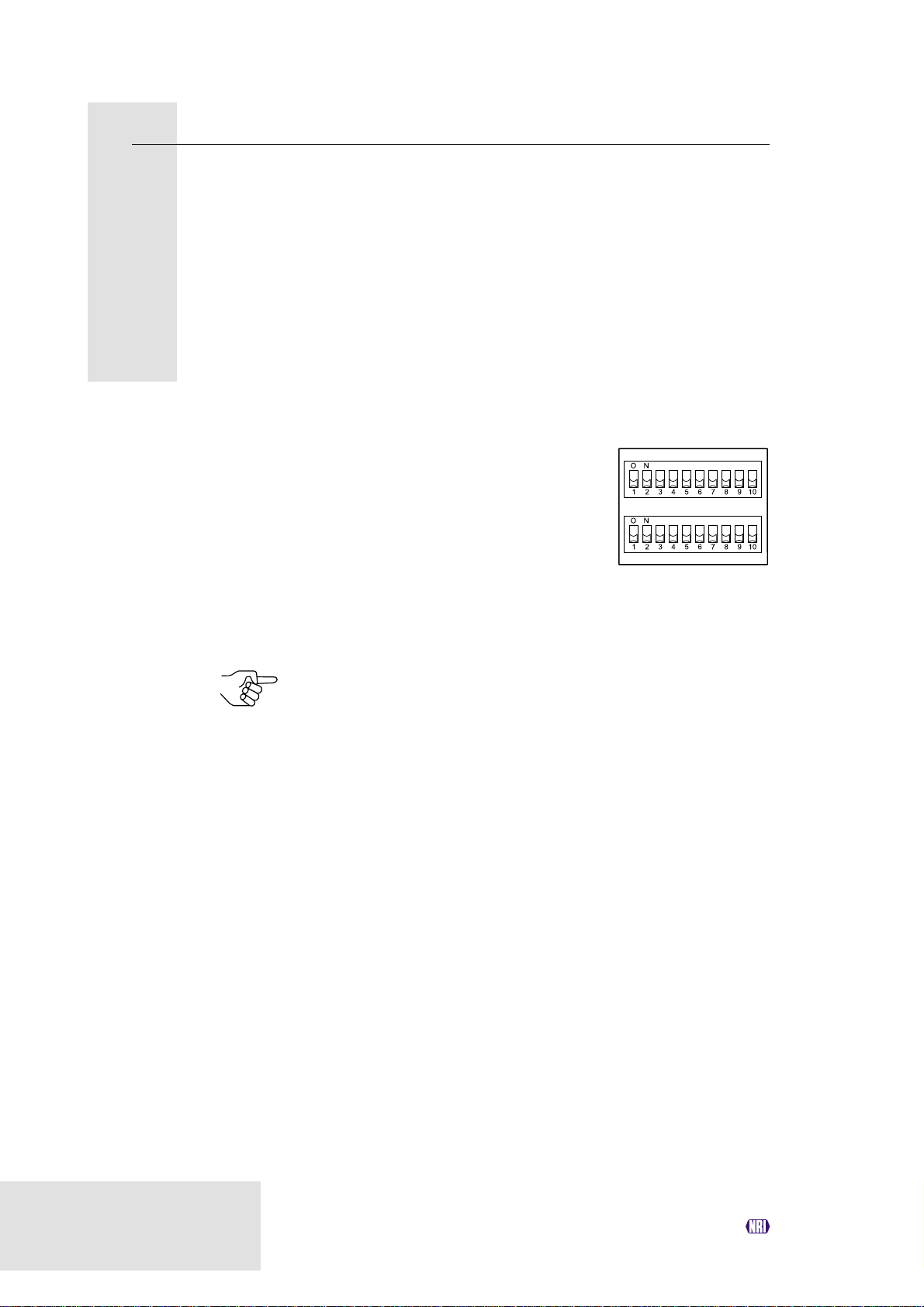
Switching blocks
On the rear, the coin validator is equipped with
two switching blocks with 10 DIL switches
S1.1-10 and S2.1-10 each.
S1
S2
Depending whether your device was programmed for coin data-management
according to a factory-made setting for one or two memory blocks (B-0 and
B-1, see label), the DIL switches will have different functions (see also
section "Single or double block data-management" in Chap. 4 "Function").
On the rear of the device you will find a brief description of the
individual switch functions.
Switch assignment with double block data-management (B-0 and B-1)
Coin channels or the coin types assigned to the coin channels can be
individually inhibited using the first eight DIL switches of the upper switching
block S1 and the lower switching block S2 (see section "Inhibit coin
channels" in Chap. 6 "Operation").
The ninth DIL switch of the upper switching block S1 does not have any
function.
The tenth DIL switch of the upper switching block S1 is used to select the
memory block (see section "Select memory block" in Chap. 6 "Operation").
The lower switching block S2 is used to teach coin types or tokens in the
teach mode (see section "Teach mode" in Chap. 6 "Operation").
14
National Rejectors, Inc. GmbH, Buxtehude
Page 15

G-13.mft MDB/S1 DESIGN
Switch assignment with single block data-management
Coin channels or the coin types assigned to the coin channels can be
inhibited using the first eight DIL switches of the upper switching block S1.
To do this the DIL switches are assigned a coin channel randomly. A group
of selected coin channels can be assigned to a switch to inhibit a number
of coin channels (see section "Inhibit coin channels" in Chap. 6 "Operation").
The ninth and tenth DIL switches of the upper switching block S1 do not have
any function.
The lower switching block S2 is used to teach coin types or tokens in the
teach mode (see section "Teach mode" in Chap. 6 "Operation") and to inhibit
these taught coins in the normal operating mode.
Return lever and return button
The return lever (1, Fig. 1a) on the top of the device is operated using the
return button on the vending machine if the coins which have already been
inserted are to be returned or a jam caused, e.g., by coins which have
become stuck needs to be removed. Operating the return lever opens the
measurement and validation area of the coin validator so that all objects in
the coin validator are transported into the return area.
Devices with front entry through a front plate do not have a return lever. Here
the measurement and validation area is opened by pressing the return
button (1, Fig. 1b) on the front plate.
National Rejectors, Inc. GmbH, Buxtehude
15
Page 16

DESIGN G-13.mft MDB/S1
Interfaces
At the bottom right-hand side on the rear of the coin validator there is a
10-pole connecting plug to the vending machine, and on the left-hand side
at the centre there is a 3-pole JST plug for connecting an external sorting
device. On the left-hand side, there is the interface to the PC programming
station and the Palm handheld. (See Fig. 1a and 1b)
Interface – vending machine
The coin validator is connected to the machine via the serial MDB interface 8
(see Fig. 1a and 1b) and a 10-pole cable via which it can receive information
from the vending machine or send information to the vending machine. The
machine operates as a master and the G-13.mft as a slave. The master can
communicate with several slaves (e.g. coin and bill validator). To ensure
unambiguous communication each device has its own MDB address. The
address of the G-13.mft as an MDB model is "01", and "15" as an S1 model.
The G-13.mft as an MDB model does not fulfil the MDB specification
on two counts, i.e. the specified voltage range and the electrical
isolation of the communication lines.
If a supply voltage of 42 V max. and electrical isolation are
desirable, an MDB converter G-55.0360 can be ordered from NRI
(ordering code 23627).
You can obtain further information about the MDB and S1 interface:
• in the "NAMA document MDB/ICP 2.0" (www.vending.org) and
• in the NRI S1 specification for the G-40 S1, which will be placed at
your disposal upon your request.
You will find a list of the commands implemented in the G-13.mft in
Chap. 9 "Technical data".
Please refer to the section "Pin assignment and connection
diagrams" also included in Chap. 9 "Technical data" for more details
on the assignment of individual plugs (pins).
16
National Rejectors, Inc. GmbH, Buxtehude
Page 17

G-13.mft MDB/S1 DESIGN
Interface – configuration (WinEMP/PalmEMP2)
To configure the coin validator the device is connected to a PC or a mobile
Palm handheld. For this purpose the G-13.mft has on the right-hand side a
10-pole PCB direct plug 10 (see Fig. 1a und 1b), which can be used to
connect the coin validator to the PC via a tester and card reader or to a Palm
handheld (see Chap. 5 "Starting up"). The device is set by means of the
configuration and diagnostics software WinEMP or PalmEMP2 (see separate
software instructions).
Interface – external sorting device
On the rear of the device, there is a 3-pole JST plug 9 (see Fig. 1a and 1b).
This plug can be used to control sorting gates for sorting inserted coins (see
sections "Control for external sorting of accepted coins" in Chap. 4 "Function"
and "Pin assignment and connection diagrams" in Chap. 9 "Technical
data").
The 3-pole sorting plug is made by the JST company and has the
type designation "ZH connector", 1.5 mm. You can obtain further
information about the plug at the Internet address www.JST.com.
National Rejectors, Inc. GmbH, Buxtehude
17
Page 18
DESIGN G-13.mft MDB/S1
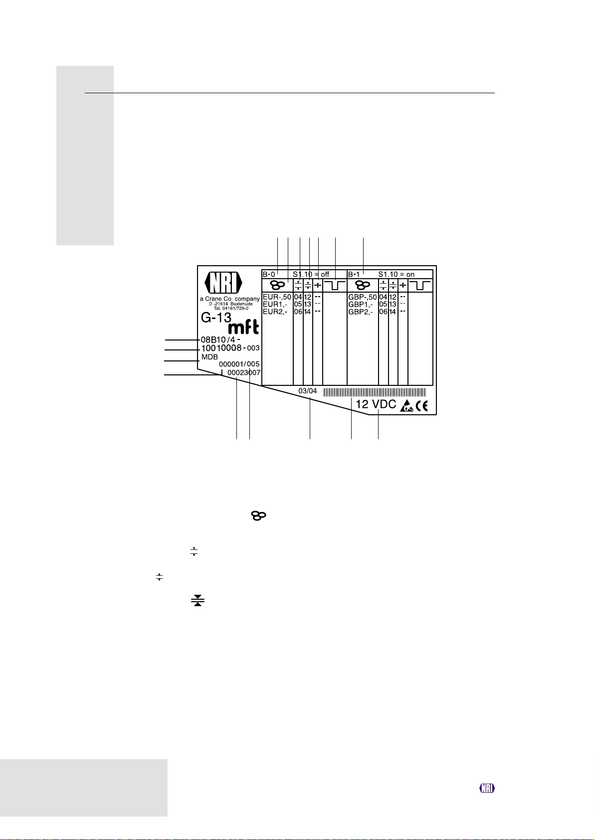
Label
The label of the coin validator contains all the data defining the device such
as device series, device type and device operation as well as customerspecific default values such as coin type and currency:
1 2 3 4
16
15
14
13
Fig. 2: Label
1 Coin information – memory block 0
(if DIL switch S1.10 on OFF)
2 Currency and coin type – memory
block 0
3 Channel number, normal coin
channel
4 Channel number, narrow coin channel
– memory block 0
5 Channel number, very narrow coin
channel – memory block 0
6 not assigned
7 Coin information – memory block 1
(if DIL switch S1.10 on ON)
– memory block 0
5 6 7
91012
811
8 Nominal voltage
9 Bar code
10 Date of manufacture
11 Consecutive device number per order
number
12 Ordering code
13 Order number
14 Device model
15 Data block number and revision
number
16 Device type
9B = Front entry model without front plate
8B = Front entry model with MINI front plate
7B = Front entry model with MIDI front plate
6B = Top entry model
18
National Rejectors, Inc. GmbH, Buxtehude
Page 19

G-13.mft MDB/S1 FUNCTION
4 Function
This chapter describes how the coin validator works, using the route which
an inserted coin takes in the coin validator:
• Coin acceptance and coin rejection
• Coin channels
• Single or double block data-management
• Accepted coin sensors
• Optional string recognition
• Control for external sorting device
• Inhibit coin acceptance
Coin acceptance and coin rejection
Coins inserted into the coin validator pass inductive and optical sensors
which check the coins and there they generate individual measurement
values. Due to the special design and arrangement of these sensors, each
coin is checked for its material properties and dimensions. An upper limit
and a lower limit are stored for each coin type, a so-called acceptance band
so that the coin validator knows whether to accept a coin or not. If the
measured values or the coin are within the acceptance band, the coin is
accepted for sale when it has passed the acceptance gate and accepted
coin sensors, but if they are outside the band, it is rejected and directed into
the return area.
The limit values of the acceptance bands are programmed by the
manufacturer according to the customers’ specifications, but can be
adjusted with the WinEMP PC configuration software or PalmEMP2.
Following a reset operation, the coin acceptance function is disabled
and must be enabled again by the vending machine.
As a standard feature, the G-13.mft refuses each further
acceptance of a coin if the G-13.mft has not been activated by the
vending machine within the last 2 seconds or if the last accepted
coin has not yet been scanned by the vending machine.
National Rejectors, Inc. GmbH, Buxtehude
19
Page 20

FUNCTION G-13.mft MDB/S1
Coin channels
The coin validator has 32 "memory slots" for coin acceptance which can be
assigned up to 32 different coin types or tokens. These "memory slots" are
termed coin channels. The acceptance band of a coin type/token is allocated
to a coin channel and the coin type/token is accepted in that channel.
In order to reject false coins reliably, frequently for one coin type, in addition to
the normal coin channel, channels with a narrow or even very narrow
acceptance band are set up (see section "Label" in Chap. 3 "Design"). The
limit values of these coin channels are closer to one another so that false coins
with similar measured values are rejected. Narrow and very narrow coin
channels, however, also possess a lower acceptance rate.
In addition, it is possible to allocate coins with different measured values but
identical coin values to different coin channels. This is how the coin validator
can, for example, accept old and new coins of the same type.
However, a coin channel is not only assigned the acceptance band of a coin
type but also other coin information which defines further processing of the
coin after its acceptance: e.g. coin value or sorting information for an
external sorting device.
Since in most cases the manufacturer’s customer-specific programming
does not take up all the coin channels, channels which are still vacant can
be assigned coin types and further information desired at any time using the
WinEMP PC configuration software or PalmEMP2. Existing configurations
can be changed.
The last eight coin channels 25 to 32 (or 9 to 16 with double block datamanagement, see section "Single or double block data-management" in
this chapter) are intended to be used for the teach mode. In these coin
channels new coin types can also be taught without configuration software,
directly via the lower switching block on the coin validator; i.e. a coin channel
is re-assigned a coin type or also a token (see section "Teach mode" in
Chap. 6 "Operation").
20
National Rejectors, Inc. GmbH, Buxtehude
Page 21

G-13.mft MDB/S1 FUNCTION
Single or double block data-management
At the manufacturer’s company, a customer-specific setting is programmed
to determine whether the 32 coin channels are to be data-managed in one
memory block or, when divided into 16 channels each, in two memory
blocks (double block data-management).
If the double block data-management has been configured, the G-13.mft can
data-manage two separately programmed (memory) blocks 0 and 1 (see
label). The 16 coin channels can be assigned to each block with different
coin types (also currencies), sorting information, etc. Only one block can be
active at a time and be used for the coin measurement and for further coin
processing. You can use the upper switching block on the device to select
the desired block (see section "Select memory block" in Chap. 6 "Operation").
Accepted coin sensors
To ensure that accepted coins actually arrive in the cash-box or in an
external sorting device and that coin acceptance has not been tampered
with, accepted coin sensors, positioned in front of the cash-box coin outlet
check whether the inserted coin drops unhindered into the cash-box chute.
A coin signal is not transmitted to the vending machine until the coin has
passed this checking function.
If the accepted coin sensors are continuously covered, e.g. by a coin pileup, coin acceptance is inhibited.
National Rejectors, Inc. GmbH, Buxtehude
21
Page 22
FUNCTION G-13.mft MDB/S1
Control for external sorting of accepted coins
In order to be able to guide the accepted coins into the cash-box or, e.g., into
change tubes or hoppers, you can equip the coin validator with the NRI sorting
device or with another sorting device. A larger sorting device can be connected
to the S1 model due to the fact that up to eight sorting ways can be used.
Sorting principle
The sorting gates are activated via the 3-pole JST plug on the rear of the
device (see Fig. 1a and 1b) and via three sorting control lines. Since these
are bidirectional sorting control lines, the coin validator can also receive
signals. If, for example, a connected hopper or change tube is full of coins
and if these units send an appropriate "Full" signal to the coin validator, all
the other coins are directed into the cash-box until the hopper/change tube
is emptied or an amount has been paid out. With the S1 model, this kind of
feedback from an external sorting device can only be provided on sorting
ways that are addressed via a single sorting control line (S1 sorting way 1,
2, 4; see table below).
Which coin type is to be sorted via which of the three sorting control lines is
programmed by the manufacturer according to the customers’ specifications
but it can be changed or re-configured with the WinEMP PC configuration
software or PalmEMP2.
While the coin validator is sorting an accepted coin (= sorting time,
see section "Sorting time of an external sorting device" in this
chapter), it cannot accept any further coins.
With the S1 model, the following sorting control lines are activated for a
specific sorting way:
S1 sorting way Sorting control line "Tube full message"
123
0 (cash-box) – – – no
1 X – – yes
2 – X – yes
3XX–no
4 – – X yes
5X–Xno
6–XXno
7XXXno
22
National Rejectors, Inc. GmbH, Buxtehude
Page 23

G-13.mft MDB/S1 FUNCTION
Sorting with NRI sorting device
When the optional NRI sorting device
is used (see also section
"Accessories" in Chap. 9 "Technical
data"), the individual coin types can
be distributed regardless of their
dimensions among the three sorting
chutes. Each chute can be defined
as a cash-box chute.
For details on how to connect
the NRI sorting device to
the coin validator, see
Chap. 5 "Starting up".
The following table shows which
sorting control line must be
activated in order to sort coins
into a specific sorting chute:
Sorting chute Sorting control line
Left 1
Middle –
Right 2
Sorting time of an external sorting device
For the switching time of an external sorting device, you can set a sorting
time using the WinEMP PC configuration software or PalmEMP2.
R
L
M
National Rejectors, Inc. GmbH, Buxtehude
23
Page 24

FUNCTION G-13.mft MDB/S1
Do not accept coin types
If coins are no longer to be accepted for payment at the vending machine,
you can inhibit coin acceptance using either the vending machine control
system or the coin validator.
Inhibit all/individual coin types via vending machine control system
The vending machine can inhibit all coin acceptance. Then the coin validator
no longer accepts coins. However, the vending machine can also inhibit only
specific coin types, e.g., if there is no more change in an external payout
device or a coin type is very frequently replaced by false coins.
For details on how these functions are programmed, please refer to "NAMA
document MDB/ICP 2.0" (www.vending.org) or to the NRI S1 specification
for the G-40 S1, which we will be pleased to place at your disposal on
request.
Inhibit individual coin types/coin type groups on the coin validator
As an alternative to the individual inhibiting of specific coin types using the
vending machine, you can inhibit individual coin types or even groups of coin
types on site using the DIL switches on the coin validator (see section "Inhibit
coin channels" in Chap. 6 "Operation").
If individual coin types are to be inhibited on a long-term basis, you
can use WinEMP or PalmEMP2 to deactivate the respective coin
channels without being required to delete the individual
configuration. This individual configuration remains available and
can be reactivated again later.
24
National Rejectors, Inc. GmbH, Buxtehude
Page 25

G-13.mft MDB/S1 STARTING UP
5 Starting up
The G-13.mft is either
• started up in a machine, or
• connected for configuration of the device with the NRI software
– to a PC and to an NRI tester for configuration with the software
WinEMP or
– to a Palm handheld for configuration with the software PalmEMP2
in the machine.
In the last section of this chapter, you can find out how to fit the NRI sorting
device to the G-13.mft before you install the device in the vending machine.
National Rejectors, Inc. GmbH, Buxtehude
25
Page 26

STARTING UP G-13.mft MDB/S1
Starting up in the vending machine
Install the MDB model of the G-13.mft in vending machines with an MDB
interface and the S1 model in vending machines with an appropriate S1
interface:
1 If necessary, install the sorting device on the coin validator (see
section "Installation of the NRI sorting device ..." in this chapter).
2 Disconnect the machine from the mains supply.
3 Hang the coin validator in the vending machine mount using the late-
ral mounting studs 1 (see Fig. 3).
4 Connect the coin validator to the machine using the 10-pole interface 3
provided and the appropriate connecting cable (see Fig. 3).
5 Reconnect the mains supply to the machine.
Make sure the correct supply voltage is connected (see label).
The G-13.mft as an MDB model does not fulfil the MDB specification
on two counts, i.e. the specified voltage range and the electrical
isolation of the communication lines.
If a supply voltage of 42 V max. and electrical isolation are
desirable, an MDB converter G-55.0360 can be ordered from NRI
(ordering code 23627).
1
1
3
2
26
1 Mounting studs
(not illustrated on the left-hand side of the device)
2 Interface –
1
Fig. 3: Installation
PC programming station (WinEMP)/
Palm handheld (PalmEMP2)
3 Interface – vending machine
National Rejectors, Inc. GmbH, Buxtehude
Page 27

G-13.mft MDB/S1 STARTING UP
Device environment for configuration software (WinEMP)
If you want the G-13.mft to be set on the PC using the diagnostics and
configuration software WinEMP, the following device environment is
connected to the PCB direct plug 2 of the coin validator (see Fig. 3 and
section "Accessories" in Chap. 9 "Technical data"):
• Tester G-19.0641
• Card reader G-19.0647 incl. chip card
WinEMP
Card reader
Fig. 4: Connect G-13.mft to PC
Tester
To find out how to connect this device environment to your PC, please refer
to the separate operating instructions for the WinEMP software "WinEMP –
The configuration and diagnostics program for NRI coin validators" (refer
also to Chap. 8 "Which functions can be set using WinEMP/PalmEMP2?").
Connection to Palm handheld (PalmEMP2)
With a Palm handheld and the NRI software PalmEMP2 the G-13.mft can
be directly configured on site inside the machine. The PalmEMP2 program
is available on the NRI homepage. To be able to connect your Palm handheld
to the coin validator, you need an NRI dongle (see section "Accessories" in
Chap. 9 "Technical data"). A connecting cable is part of the scope of delivery.
Should you wish the memory blocks of the G-13.mft to be updated and for
this a data block download to be performed, a WinEMP licence with
PalmEMP2 download rights must be additionally ordered (see above and
the section "Accessories" in Chap. 9 "Technical data"). Having done this, the
new data blocks can be loaded initially into the Palm handheld, using
WinEMP from your PC’s internal hard disk, then from the Palm handheld into
the coin validator.
G-13.mft
To find out how to connect the Palm handheld to the PCB direct plug 2 (see
Fig. 3) and how to install and operate PalmEMP2, please refer to the
separate operating instructions for the software (refer also to Chap. 8
"Which functions can be set using WinEMP/PalmEMP2?").
National Rejectors, Inc. GmbH, Buxtehude
27
Page 28

STARTING UP G-13.mft MDB/S1
Installation of the NRI sorting device ...
If you want to operate the G-13.mft with the NRI sorting device, you must use
a special bracket to install the NRI sorting device on the top entry model or
on the front entry model:
... on the top entry model
1 If necessary, fasten chute extension 1 with screw 2 to sorting
device 3 (see Fig. 5a).
2 Fasten mounting frame 4 by means of screws 5 and 6 to the rear of
the sorting device.
3 Hang the coin validator by its mounting studs 7 in the mounting
frame.
4 Use the 3-pole sorting plug 8 on the PCB 9 and on the rear of the
coin validator to connect the sorting device to the G-13.mft with the
help of the appropriate sorting cable.
5 Use the 10-pole connecting plug 10 on the PCB 9 and on the rear of
the coin validator to connect the sorting device to the G-13.mft for
power supply of the sorting solenoids with the help of the appropriate
connecting cable.
6 Use the 10-pole connecting plug 10 on the PCB 9 and the same
connecting cable to connect the coin validator to the vending
machine (see also section "Starting up in the vending machine" in
this chapter).
28
National Rejectors, Inc. GmbH, Buxtehude
Page 29

G-13.mft MDB/S1 STARTING UP
4
5
6
7
7
1
3
2
9
10
8
Fig. 5a: Connect G-13.mft, top entry model, to NRI sorting device
National Rejectors, Inc. GmbH, Buxtehude
29
Page 30

STARTING UP G-13.mft MDB/S1
... on the front entry model
1 If necessary, fasten holding plate 1 with two screws 2 and 3 to
sorting device 4 (see Fig. 5b).
2 Remove screw 5 from coin validator.
3 Use the holding plate to insert the sorting device from the right-hand
side onto the coin validator.
4 Fasten the sorting device with screw 5 to the coin validator.
5 Use the 3-pole sorting plug 6 on the PCB 7 and on the rear of the
coin validator to connect the sorting device to the G-13.mft with the
help of the appropriate sorting cable.
6 Use the 10-pole connecting plug 8 on the PCB 7 and on the rear of
the coin validator to connect the sorting device to the G-13.mft for
power supply of the sorting solenoids with the help of the appropriate
connecting cable.
7 Use the 10-pole connecting plug 8 on the PCB 7 and the same
connecting cable to connect the coin validator to the vending
machine (see also section "Starting up in the vending machine" in
this chapter).
30
4
7
8
6
Fig. 5b: Connect G-13.mft, front entry model,
to NRI sorting device
National Rejectors, Inc. GmbH, Buxtehude
1
3
2
5
Page 31

G-13.mft MDB/S1 OPERATION
6 Operation
In this chapter you will find out how to:
• Inhibit coin types or their coin channels
• Teach coin types in teach mode
• Select the desired memory block 0 or 1
Inhibit coin channels ...
Depending whether the 32 coin channels are being data-managed in one or,
when divided in 16 coin channels each, in two memory blocks (B-0 and B-1,
see label), the coin types are inhibited differently.
... with double block data-management (B-0 and B-1)
Using the first eight DIL switches of the two switching blocks S1 and S2 on
the rear of the coin validator each of the 16 coin channels or each coin type
assigned to a specific coin channel can be inhibited individually, i.e. this coin
type is not accepted for payment on the vending machine.
The 16 DIL switches inhibit the following coin channels:
Switching block S1
DIL switch off on
1 Coin channel 1 vacant inhibited
2 Coin channel 2 vacant inhibited
3 Coin channel 3 vacant inhibited
4 Coin channel 4 vacant inhibited
5 Coin channel 5 vacant inhibited
6 Coin channel 6 vacant inhibited
7 Coin channel 7 vacant inhibited
8 Coin channel 8 vacant inhibited
Switching block S2
DIL switch off on
1 Coin channel 9 vacant inhibited
2 Coin channel 10 vacant inhibited
3 Coin channel 11 vacant inhibited
4 Coin channel 12 vacant inhibited
5 Coin channel 13 vacant inhibited
6 Coin channel 14 vacant inhibited
7 Coin channel 15 vacant inhibited
8 Coin channel 16 vacant inhibited
S1
S2
S1
S2
National Rejectors, Inc. GmbH, Buxtehude
31
Page 32

OPERATION G-13.mft MDB/S1
Please refer to the label of the device to see which coin type has been
assigned to which coin channel at the factory. However, this assignment
can be changed at any time using the WinEMP PC configuration software
or PalmEMP2.
If all coin types are to be accepted for payment at the vending machine, the
DIL switches S1.1–S1.8 and S2.1–S2.8 of the two switching blocks are in
the lower position on OFF. If you want to inhibit a coin channel, you only need
to move the respective DIL switch toward the top to ON.
Example
(the coin validator is no longer supposed to accept the coin(s) assigned to coin
channels 3 and 10, which means that coin channels 3 and 10 must be
inhibited)
With the DIL switches in these positions, the coin validator no longer
accepts the coin type(s) assigned to coin channels 3 and 10!
If a normal coin channel and a narrow coin channel have been
programmed on the coin validator for one coin type, the normal coin
channel must be inhibited as described above in order to activate
the narrow coin channel. If both channels are activated, the wider
acceptance band of the normal coin channel is used.
If a coin type is to be inhibited, both coin channels must be
inhibited.
32
National Rejectors, Inc. GmbH, Buxtehude
Page 33

G-13.mft MDB/S1 OPERATION
... with single block data-management
Coin channels can be inhibited using the first eight DIL switches S1.1–S1.8
of the upper switching block on the rear of the device. To do this the DIL
switches are assigned a coin channel randomly. Several coin channels can
also be assigned to one switch. This switch will then inhibit a coin group (e.g.
all coin channels of a currency, all coin channels of a coin type (normal and
narrow coin channels)).
The assignment of DIL switches to coin type/coin group is programmed at
the factory on a customer-specific basis. However, this setting can be
changed with the WinEMP PC configuration software or PalmEMP2.
If all coin types assigned to the DIL switches are to be accepted for payment
at the vending machine, the DIL switches must be in the lower position (on
OFF).
If you want to inhibit a coin channel, you only need to move the respective DIL
switch toward the top to ON.
The following examples are designed to illustrate the procedure using the
label. The label shows the manufacturer’s assignment of coin type/coin
group.
Any coin types or tokens that may have been taught in coin
channels 25 to 32 are inhibited using the DIL switches of the lower
switching block S2 in the assignment according to which they were
taught (see section "Teach mode" in this chapter).
National Rejectors, Inc. GmbH, Buxtehude
33
Page 34

OPERATION G-13.mft MDB/S1
Example – Inhibit a currency as coin group
(the coin validator must only accept euros and no longer the British currency)
With this setting the coin validator only accepts euros.
Example – Activate narrow acceptance bands/coin channels as coin group
(the coin validator must accept the 1-euro coin and the British 1-pound coin in the
narrow acceptance band and not in the normal one, i.e. it must inhibit the normal
acceptance band)
With this setting the coin validator accepts coins in the narrow coin channel and
not in the normal one.
Example – Inhibit single coin type
(the coin validator must no longer accept the 2-euro coin or the British 2-pound coin)
With this setting the coin validator no longer accepts the 2-euro coin or the British
2-pound coin.
At a coin validator with the label described above, it would also be
possible to inhibit the euro currency via DIL switch S1.4.
34
With the aid of several DIL switches more than one coin type or coin
group can be inhibited simultaneously.
National Rejectors, Inc. GmbH, Buxtehude
Page 35

G-13.mft MDB/S1 OPERATION
Teach mode
Coin channels can also be taught directly without configuration software via
the switching block on the coin validator, i.e. a coin channel is reassigned a
coin type or even a token without having to remove the coin validator from
the vending machine. You can also widen the acceptance band for the
selected coin channel so that the rejection of genuine coins is reduced. For
the teaching procedure, coin channels 9 to 16 of the activated memory block
are available with double block data-management and coin channels 25 to
32 with single block data-management (see also section "Single or double
block data-management" in Chap. 4 "Function").
Switch assignment with double block data-management (in teach mode)
Switching block S2
DIL switch off on
1 Coin channel 9 – teach
2 Coin channel 10 – teach
3 Coin channel 11 – teach
4 Coin channel 12 – teach
5 Coin channel 13 – teach
6 Coin channel 14 – teach
7 Coin channel 15 – teach
8 Coin channel 16 – teach
9 Teach mode switch off switch on
10 Acceptance band normal wide
S1
S2
Switch assignment with single block data-management (in teach mode)
Switching block S2
DIL switch off on
1 Coin channel 25 – teach
2 Coin channel 26 – teach
3 Coin channel 27 – teach
4 Coin channel 28 – teach
5 Coin channel 29 – teach
6 Coin channel 30 – teach
7 Coin channel 31 – teach
8 Coin channel 32 – teach
9 Teach mode switch off switch on
10 Acceptance band normal wide
S1
S2
National Rejectors, Inc. GmbH, Buxtehude
35
Page 36

OPERATION G-13.mft MDB/S1
Teach coin channels
To assign a coin type to a new coin channel, please proceed as follows:
If you want to use the lower switching block to inhibit individual
coins, remember the current switch settings so that you can restore
them easily for the normal operating mode at the end.
1 Set all DIL switches 1–10 of the lower
switching block toward the bottom to OFF.
2 Set DIL switch S2.9 toward the top to ON.
Now the device is in teach mode to teach
the coin channels.
3 Release the coin channel to be taught
(9–16 or 25–32, here: 11 or 27) by setting
the appropriate DIL switch (S2.1–8, here:
S2.3) toward the top to ON.
4 Insert at least 10 coins of the new coin type/token into the coin
validator or vending machine.
After the 10
operated once (solenoid attraction sound). Additional coins can be
inserted.
th
coin has been inserted, the acceptance gate is
Now you can save the measured values generated by the inserted coins in
either a normal (a) or a wide (b) acceptance band. A wide acceptance band
is only an appropriate choice when you only have a limited selection of coins
at your disposal for the purpose of teaching tokens and would still like to
program greater tolerance limits.
To save with the normal acceptance band:
5a) Set DIL switch S2.9 toward the bottom
to OFF.
Successful saving is signalled by the
acceptance gate attracting once, an
error when saving is indicated by the acceptance gate attracting
twice, if, for example, the acceptance band of the coins inserted and
an acceptance band of an already programmed coin channel overlap.
To abort the operation, first set the DIL switch of the respective coin
channel (here: S2.3) and then DIL switch S2.9 toward the bottom to
OFF.
36
National Rejectors, Inc. GmbH, Buxtehude
Page 37

G-13.mft MDB/S1 OPERATION
To save with a wide acceptance band:
5b) Set DIL switch S2.10 toward the top to
ON.
The acceptance band has been
widened.
Now you can set DIL switch S2.9
toward the bottom to OFF.
Successful saving is signalled by the
acceptance gate attracting once, an
error when saving is indicated by the acceptance gate attracting
twice, if, for example, the acceptance band of the coins inserted and
an acceptance band of an already programmed coin channel overlap.
To abort the operation, first set the DIL switch of the respective coin
channel (here: S2.3) as well as DIL switch S2.10 and then DIL
switch S2.9 toward the bottom to OFF.
6 Set DIL switch S2.1–8 (here: S2.3) and S2.10, if necessary, for the nor-
mal operating mode (see section "Inhibit coin channels" in this chapter).
The new coin type/token will now be accepted for payment by the coin
validator.
The DIL switches of the lower switching block S2 can be used to
inhibit the taught coins or tokens in the assignment according to
which they have been taught.
Select memory block (only for double block data-management)
If the 32 coin channels, divided in 16 coins channels each, are data-managed
in two (memory) blocks (B-0 and B-1, see label), these (memory) blocks are
programmed separately from one another by the manufacturer on a customerspecific basis. The data of the two blocks 0 and 1 differ when they are being used
in the device, e.g. by the acceptance of different currencies, such as national
currency and euro. Only one block can be active at a time and be used for the
coin measurement and for further coin processing.
If the coin validator is to access the other memory block and, e.g., accept euro
coins instead of national currency coins, the correct block can be selected using
the upper switching block.
Set DIL switch S1.10 of the upper switching block downward to OFF to select
memory block 0 and upward to ON to select memory block 1.
Memory block 0 selected
National Rejectors, Inc. GmbH, Buxtehude
Memory block 1 selected
37
Page 38

CLEANING G-13.mft MDB/S1
7 Cleaning
The coin validator must only be wiped clean from time to time with a damp
cloth (lukewarm water with some detergent). Beyond that, no further
maintenance work is required.
Under no circumstances may the cloth be so wet that fluid
runs into the device. Otherwise the PCB will be damaged.
Do not use any solvents or scouring agents that will attack the
plastic material of the device.
1 Pull the vending machine’s mains plug.
2 Carefully open the flight deck 1 on the left-hand side and hold it open
(Fig. 6).
3 Use a cloth to wipe off the coin runway inside the coin validator.
4 Close the flight deck again.
5 Reconnect the vending machine to the mains supply.
Fig. 6: Open the flight deck of the coin validator
1
38
National Rejectors, Inc. GmbH, Buxtehude
Page 39

G-13.mft MDB/S1 WHICH FUNCTIONS CAN BE SET USING W INEMP/PALMEMP2?
8 Which functions can be set using
WinEMP/PalmEMP2?
The software WinEMP or PalmEMP2 is used for diagnostics purposes and
configuration of NRI coin validators as well as for the purpose of updating the
data blocks in the device memory.
WinEMP is PC software and part of a programming station for the workshop.
For more information, please see the section "Accessories" in Chap. 9
"Technical data".
PalmEMP2 is software stored on a Palm handheld as additional application. If
the Palm handheld is linked to the coin validator via an NRI dongle (see section
"Accessories" in Chap. 9 "Technical data"), the G-13.mft can be directly
configured on site inside the machine.
Both programs identify the connected coin validator and the device’s own
data and present them on the screen of your PC or on the Palm handheld
display.
The device functions listed below can be set using WinEMP/PalmEMP2
(see separate software instructions).
• Attraction duration
• Sorting time
• Assignment
– coin value – coin type
– DIL switch – coin type (internal inhibit, only with single block data-
management)
– sorting control line/sorting way – coin type
• Coin acceptance band after the insertion of
– genuine coins
– false coins
• Teach coin channels
• Deactivate coin channels individually using coin validator software
• Data block update for current coin information
For the data block update, an additional module must be ordered in
addition to the WinEMP software’s basic module (see section
"Accessories" in Chap. 9 "Technical data").
If you wish to perform data block updates using the Palm handheld,
you need the WinEMP software with the PalmEMP download rights,
which are stored on the WinEMP chip card (see section
"Accessories" in Chap. 9 "Technical data").
National Rejectors, Inc. GmbH, Buxtehude
39
Page 40

TECHNICAL DATA G-13.mft MDB/S1
9 Technical data
Supply voltage 10–16 V DC
Power consumption Standby mode: < 30 mA
Measuring mode: approx. 100 mA + approx. 3 W
(acceptance gate)
Transmitter (active low) Output current
Residual current
Receiver (active high) Input current
Input current
(active): 30 mA at 1V
max
(inactive): 30 µA
max
(active): 100 µA at 4V
max
(inactive): 30 µA
max
Temperature range -25 to +70 °C (temperature change max. 0.2 °C/min)
Rel. humidity 15 to 93 %
Condensation not permitted
Dimensions Height: 102 mm
Width: 89 mm
Depth: 52 mm
Installation tilt ± 2°
Coin dimensions Ø 15–31.5 mm (optionally up to 32.5 mm)
thickness 1.5–2.5 mm, optionally 1.5–3.3 mm
Coin acceptance 32 coin channels
Acceptance speed 2 coins/second
Vending machine interface 9600 baud, 9-bit, N, 1, 1, 5 V TTL, Tx active low,
Rx active high
Protocol in compliance with MDB/ICP version 2.0,
NAMA or in compliance with G-40 S1, NRI
Sorting interface Company: JST, www.jst.com
Type: ZH connector; 1.5 mm
40
National Rejectors, Inc. GmbH, Buxtehude
Page 41

G-13.mft MDB/S1 TECHNICAL DATA
CE certification
The CE certificate (CE = Communautés Européennes) confirms
that our products comply with specified basic requirements of
the applicable directive. The CE certificate is not a quality
assurance certificate in terms of the quality expected by the
manufacturer but only in terms of the quality demanded legally. It is a pure
administrative certificate and is intended only as proof of compliance with
the directives for the monitoring authorities and not directed at clients or final
customers.
Which directives were applied can be seen in the declaration of conformity.
The manufacturer must keep this declaration available for the monitoring
authorities only (for a minimum period of 10 years after the last product has
been introduced to the market). However, upon request we can provide
copies of this declaration for our customers.
The following directives and their subsequent changes can be partially
applied to our devices:
1. The EMC Directive (89/336/EEC)
for devices which cause electromagnetic interference or are interfered
with by such.
2. The Low Voltage Directive (73/23/EEC)
for electrical equipment which is used with a nominal voltage of
between 50 and 1000 V AC and 75–1500 V DC.
3. The CE Certificate Labelling Directive (93/68/EEC)
Modification directive regarding the application and use of CE labels.
National Rejectors, Inc. GmbH, Buxtehude
41
Page 42

TECHNICAL DATA G-13.mft MDB/S1
Pin assignment and connection diagrams
On the following pages you will find connection diagrams and pin assignment
for the connection of the G-13.mft to the vending machine and an external
sorting device
G-13.mft – vending machine
Pin 1 ground (GND)
Pin 2 not assigned
Pin 3 master receive, TxD, O.C. active low
Pin 4 not assigned
Pin 5 master transmit, RxD, 5 V active low
Pin 6 not assigned
Pin 7 reserved for wake-up line
Pin 8 +5 V output
Pin 9 not assigned
Pin 10 +12 V DC supply
12
109
42
National Rejectors, Inc. GmbH, Buxtehude
Page 43

G-13.mft MDB/S1 TECHNICAL DATA
National Rejectors, Inc. GmbH, Buxtehude
43
Page 44
TECHNICAL DATA G-13.mft MDB/S1
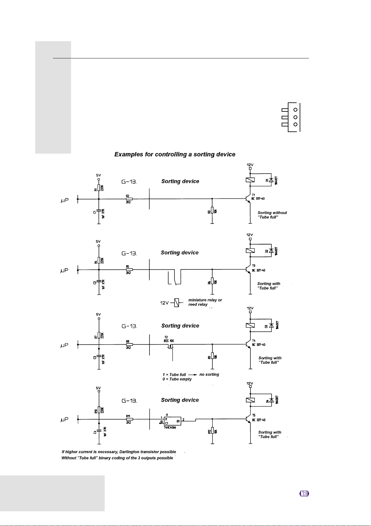
G-13.mft – external sorting device
Pin 1 Sorting control line 1
Pin 2 Sorting control line 2
Pin 3 Sorting control line 3
1
3
44
National Rejectors, Inc. GmbH, Buxtehude
Page 45

G-13.mft MDB/S1 TECHNICAL DATA
Commands, status and error messages
In the following tables you will find commands, status and errors messages
that are implemented for the MDB or S1 protocol.
For further details, please refer to "NAMA document MDB/ICP 2.0"
(www.vending.org) and to the NRI S1 specification for the G-40 S1,
which we will be pleased to place at your disposal on request.
Implemented MDB commands
Byte 1 Byte 2 Command Data [Bytes
expected/
returned]
00h – Reset [0/ACK]
01h – Status [0/23]
02h – Tube Status [0/18]
03h – Poll [0/1..16]
04h – Coin Type [4/ACK]
05h – Dispense [1/ACK]
07h 00h Expansion Command Identification [0/33]
07h 05h Expansion Command Status [0/2]
MDB status and error codes (reply to poll)
Byte 1 Byte 2 Meaning
01h – Return lever pressed
05h – Two coins (coin inserted too quickly)
08h – Program error/data memory
09h – Accepted coin sensor (CP3/CP4) did not detect
- within specified measuring time
0Bh – Reset occurred
0Ch – Coin pile-up
20h – 3Fh – Unknown coin rejected (slug counter)
40h – 4Fh 00h Coin 0–15 accepted
70h – 7Fh 00h Coin 0–15 rejected
National Rejectors, Inc. GmbH, Buxtehude
45
Page 46

TECHNICAL DATA G-13.mft MDB/S1
Implemented S1 commands
Byte 1 Byte 2 Command Data [Bytes
expected/
returned]
00h – Reset [0/ACK]
01h – Status [0/30]
03h – Poll [0/1..16]
04h – Coin Type [4/ACK]
06h – Change Default Value [9/ACK]
07h 00h Expansion Command Identification [0/33]
07h 01h Expansion Current Value [0/13]
07h 03h Expansion Command Diagnose 1 [0/ACK]
07h 04h Expansion Command Diagnose 2 [0/5]
S1 status and error codes (reply to poll)
Byte 1 Meaning
00h – 10h Status and error messages
11h – 1Fh vacant
20h – 3Fh Slug counter
40h – 4Eh Error with coin acceptance
4Fh – 5Fh vacant
60h – 67h Sort-info way 0–7
68h – 7Fh vacant
80h – 8Fh Coin info with successful acceptance
9Fh – FFh Coin info with incorrect acceptance
S1 standard settings (following reset)
All settings performed by the vending machine control system are transient.
Following a reset operation, the following standard settings are applicable
until the control system changes any settings:
Description Value
Sorting way, cash-box 0
Sorting ways of coins 1..16 predefined setting acc. to data block
Sorter override (coin in cash-box) 0 (each coin will be sorted)
46
National Rejectors, Inc. GmbH, Buxtehude
Page 47

G-13.mft MDB/S1 TECHNICAL DATA
Mounting dimensions
Top entry model
View from front
View from rear
National Rejectors, Inc. GmbH, Buxtehude
47
Page 48

TECHNICAL DATA G-13.mft MDB/S1
View from above
View from below
48
National Rejectors, Inc. GmbH, Buxtehude
Page 49

G-13.mft MDB/S1 TECHNICAL DATA
View from the side
National Rejectors, Inc. GmbH, Buxtehude
49
Page 50

TECHNICAL DATA G-13.mft MDB/S1
Front entry model without front plate
View from front
View from rear
50
National Rejectors, Inc. GmbH, Buxtehude
Page 51

G-13.mft MDB/S1 TECHNICAL DATA
View from above
View from below
National Rejectors, Inc. GmbH, Buxtehude
51
Page 52

TECHNICAL DATA G-13.mft MDB/S1
View from the side
52
National Rejectors, Inc. GmbH, Buxtehude
Page 53

G-13.mft MDB/S1 TECHNICAL DATA
Front entry model with MIDI front plate
View from front and rear
National Rejectors, Inc. GmbH, Buxtehude
53
Page 54

TECHNICAL DATA G-13.mft MDB/S1
View from right
54
National Rejectors, Inc. GmbH, Buxtehude
Page 55

G-13.mft MDB/S1 TECHNICAL DATA
Front entry model with MINI front plate
View from front and rear
National Rejectors, Inc. GmbH, Buxtehude
55
Page 56

TECHNICAL DATA G-13.mft MDB/S1
View from right
56
National Rejectors, Inc. GmbH, Buxtehude
Page 57

G-13.mft MDB/S1 TECHNICAL DATA
Accessories
In order to test the coin validator or adapt it to your individual needs, you can
acquire the following accessories from NRI:
Front plates
For the G-13.mft two different
front plates are available, which
are fitted from the left-hand side
to the front entry model of the
coin validator, so that the cut-out
in the machine wall provided for
the installation is enclosed:
• MIDI front plate
(ordering code 5508)
• MINI front plate
(ordering code 20854)
MINI
Coins are inserted into the device
via the top slot in the front plate.
Not accepted coins that are
directed into the return area are
returned via the lower slot.
MIDI
National Rejectors, Inc. GmbH, Buxtehude
57
Page 58

TECHNICAL DATA G-13.mft MDB/S1
Sorting device ...
For the sorting of the G-13.mft, a 3-fold sorting device is available. Depending
whether you have a top entry model or a front entry model, you will require
a special bracket to install the sorting device on the G-13.mft.
For details on how to connect the sorting device, see Chap. 5 "Starting up".
... for top entry model
The sorting device (ordering code 24761) is
fastened using a mounting frame (ordering
code 24157) to the top entry model of the
G-13.mft.
... for front entry model
The sorting device (ordering code 24761) is
fastened using a holding plate (ordering code
24153) to the front entry model of the G-13.mft.
58
National Rejectors, Inc. GmbH, Buxtehude
Page 59

G-13.mft MDB/S1 TECHNICAL DATA
Configuration software
To be able to react as quickly as possible to new false coins, in the workshop
or on site, and enable you to make your individual adjustments, the coin
validator can be connected to:
• The NRI PC programming station consisting of
– Configuration and diagnostics software "WinEMP", including card
reader und chip card (ordering code: 20119 for basic module and
20169 for additional module)
– Tester G-19.0641 (ordering code 12922)
• The NRI Palm application "PalmEMP2", which is available on the NRI
homepage. To be able to connect a Palm handheld m125 to the coin
validator, you need a dongle with the ordering code 23760; for an m105,
a dongle with the ordering code 23761. If you want to perform data block
downloads with the help of a Palm handheld, you need the WinEMP
software (see above) with PalmEMP2 download rights (ordering code
23649), which are saved on the WinEMP chip card.
You can also use a 9-pole D-SUB plug (ordering code 23764) to
connect the Palm handheld via the universal dongle. However, the
Palm handheld must be equipped with an interface that can be
connected to the serial HotSync cable (available with PalmTM).
For further details about the individual PalmEMP2 dongles, please
refer to the NRI homepage (www.nri.de).
For details on which settings can be made with the help of WinEMP and
PalmEMP2, please see Chap. 8 "Which functions can be set using WinEMP/
PalmEMP2?" For details on how to carry out these settings, please refer to
the separate software instructions.
National Rejectors, Inc. GmbH, Buxtehude
59
Page 60

INDEX G-13.mft MDB/S1
Index
A
Accentuations in the text 7
Acceptance
band 19, 63
gate 19, 63
of coins 19
speed 40
Accepted coin sensors 21, 63
Accessories 57
Advantages 9
Attraction duration 63
B
Bar code 18
Block 21
definition 63
select (double block data-management
only) 37
C
Cash-box 12
CE
certificate labelling directive 41
certification 41
Change tubes, external 22
Channel 20, 63
Cleaning 38
Coin
acceptance 40
band 20, 64
channels 20, 63
narrow 20
normal 20
teach 20, 35
very narrow 20
dimensions 40
insert funnel 12, 14
outlet 12, 14
properties 63
type 18, 63
teach 20, 35
value 63
Commands
MDB 45
S1 46
Condensation 40
Configuration 39
Connection
diagram
G-13.mft – external sorting 44
G-13.mft – vending machine 42
Palm handheld (PalmEMP2) 27
PC (WinEMP) 27
sorting device 26, 28
vending machine 26, 28, 30
Conventions, instructions 7
Currency 18
D
Data block
number 18
update 27, 39, 59, 63
Default status 46
Design 12
Device
number 18
type 18
Diagnostics 39
DIL switches 14, 31
double block data-management 14
inhibit coins
double block data-management 31
single block data-management 33
single block data-management 15, 33
teach mode
double block data-management 35
single block data-management 35
Dimensions 40
front entry model 50
top entry model 47
with MIDI front plate 53
with MINI front plate 55
Discharge, electrostatic 11
Documentation, additional 7
Double block data-management 21
60
National Rejectors, Inc. GmbH, Buxtehude
Page 61

G-13.mft MDB/S1 INDEX
E
ECV 64
Electrostatic discharge 11
EMC directive 41
Error codes
MDB 45
S1 46
F
Factory setting 46
False coins, reject 20
Flight deck, open 38
Front plate 9, 12, 57
MIDI 9, 12, 57
MINI 9, 13, 57
Function 19
G
General information
G-13.mft 8
instructions 7
Glossary 7, 63
Guide 7
H
Header 45
Hopper, external 22
Humidity, relative 40
I
Inhibit
coin channels 31
double block data-management 31
single block data-management 33
coin types 24
double block data-management 31
single block data-management 33
Input current, receiver 40
Installation
Palm handheld (PalmEMP2) 27
PC (WinEMP) 27
tilt 40
Instructions, additional 7
Interface
external sorting 12, 13, 17
PC/Palm handheld 12, 13
vending machine 12, 16, 40
J
JST plug 17, 22
L
Label 18
Low voltage directive 41
M
Maintenance 38
Manuals, additional 7
Manufacture date 18
Markings in the text 7
MDB 64
commands 45
model 9
specification 16
Measurement area 14
Memory block 21
definition 65
select (double block data-management only)
37
Models 9
Mounting
dimensions
front entry model 50
top entry model 47
with MIDI front plate 53
with MINI front plate 55
studs 12
Multi-frequency technology 8
N
NAMA 16
Nominal voltage 18
Notes 7
O
Open coin validator 38
Operating instructions, additional 7
Operation 31
Order number 18
Ordering code 18
Output current, transmitter 40
National Rejectors, Inc. GmbH, Buxtehude
61
Page 62

INDEX G-13.mft MDB/S1
P
PalmEMP2 8
connection 27, 59
dongle 59
functions 39
ordering code 59
Pictograms in the text 7
Pin assignment
G-13.mft – external sorting device 44
G-13.mft – vending machine 42
Poll, replies to
MDB 45
S1 46
Power consumption 40
Programming 39
Proper use 10
R
Receiver, input current 40
Requests to perform an action 7
Reset status, S1 model 46
Return
area 12, 14
button 13, 15
lever 12, 15
S
S1 64
commands 46
model 9
specification 16
Safety instructions 7, 10
Single block data-management 21
Sorting
control line 64
device
external 14
install 26, 28
ordering code 58
gates 17, 22, 64
time 22, 23, 64
ways, S1 model 22
Specification
MDB 16
S1 16
Standard settings (following reset, S1 model)
46
Starting up 25
at the vending machine 26, 28, 30
with sorting device 26, 28
Status messages 45
MDB 45
S1 46
String sensor 64
Supply voltage 40
Switching block 14, 31, 65
double block data-management 14
inhibit coins
double block data-management 31
single block data-management 33
single block data-management 15, 33
teach mode
double block data-management 35
single block data-management 35
Symbols in the text 7
T
Teach mode 35
description 65
Technical data 40
Temperature range 40
Tester
device environment, PC programming station
59
ordering code 59
Token 65
teach 20, 35
Top entry 9
Transmitter, output current 40
Types 9
V
Validation area 14
Variants 9
Versions 9
W
WinEMP
connection 27, 59
device environment, PC programming station
27, 59
functions 39
ordering code 59
62
National Rejectors, Inc. GmbH, Buxtehude
Page 63

G-13.mft MDB/S1 GLOSSARY
Glossary
Acceptance band A range of acceptable measured values of one → coin type
(with specific → coin properties) defined by an upper and
lower limit value.
Acceptance gate The acceptance gate diverts the inserted coins into the
acceptance or return area of the coin validator.
Accepted coin sensors The accepted coin sensors are positioned in front of the
cash-box coin outlet of the coin validator and check whether
accepted coins fall unhindered into the cash-box chute.
Attraction duration The attraction duration is used to specify the period of time for
which the solenoid is to attract the → acceptance gate in
order to guide the accepted coins to the cash-box or an
external sorting device.
Block → Memory block
Channel → Coin channel
Coin acceptance band → Acceptance band
Coin channel Coin channels are used to describe → coin types using their
different → coin properties (alloy, size, etc.). The required
coin properties of a coin type are defined in →acceptance
bands which are assigned to the coin channels together with
other coin information for further processing along.
Coin properties Coin properties are measured when a coin is inserted into the
coin validator. These are e.g. material, thickness, volume,
minting, diameter, mass, hardness, etc.
Coin type One coin type includes all coins for which the → coin
properties agree.
Coin value The value of a → coin type that is transmitted from the coin
validator to the machine.
Data block update When updating a data block (set) (2 data blocks) using
WinEMP or PalmEMP2, the data blocks for the connected
coin validators are loaded quickly and easily from the internal
hard disk of your PC into the coin validator. By doing this, a
new data block is loaded into → memory block 0 (and
memory block 1). The new data blocks contain different
configurations of → coin channel data, e.g. current limit
values of the → acceptance bands for a currency or new coin
or sorting information.
National Rejectors, Inc. GmbH, Buxtehude
63
Page 64

GLOSSARY G-13.mft MDB/S1
ECV Electronic Coin Validator
MDB Multi Drop Bus. The abbreviation defines a serial interface
specification for an internal communication protocol for
vending machines.
For further information on the MDB interface, please refer to
"NAMA document MDB/ICP 2.0" (www.vending.org).
Memory block Memory of the coin validator. At the manufacturer’s company,
a customer-specific setting is programmed to determine
whether the 32 → coin channels of the G-13.mft are to be
data-managed in one memory block (single block datamanagement) or, when divided into 16 channels each, in two
memory blocks (double block data-management). Two
(memory) blocks 0 and 1 can be used to data-manage two
independent configurations of coin channel data (e.g. two
currencies). However, for coin validator operation, only one
memory block with 16 channels can be active at a time; the
other block is inhibited.
The memory block(s) can be updated using WinEMP or
PalmEMP2 (→ data block download).
S1 This abbreviation defines a serial, NRI-specified and
→ MDB-based interface to the vending machine.
You will find detailed information on the serial S1 interface in
the NRI S1 specification for the G-40 S1, which we will be
pleased to place at your disposal upon your request.
Sorting control line To sort the cash coins with an external sorting device, the
coin validator has three sorting control lines, which can be
used to activate three sorting ways with the MDB model and
up to eight sorting ways with the S1 model.
Sorting gate The sorting gates are activated in the coin validator depending
on the run time of accepted coins and direct the coins to be
sorted into the return area or coin outlet towards the cash-box
or external sorting device.
Sorting time The sorting time specifies the switching times of an external
sorting device.
String sensor The coin validator’s optional sensor recognizes a coin inserted
with a piece of string attached to it. The coin is not accepted
for payment.
64
National Rejectors, Inc. GmbH, Buxtehude
Page 65

G-13.mft MDB/S1 GLOSSARY
Switching blocks The two switching blocks are located on the rear of the coin
validator and incorporate 10 DIL switches each. Each switch
has a specific function, e.g. inhibiting individual or grouped →
coin channels.
Teach mode In the teach mode, the last eight → coin channels can be
assigned new coin types or tokens on site at the vending
machine, which means that these newly configured coins
are accepted in the respective coin channel.
Token Token are accepted for payment at machines instead of
coins in a currency.
National Rejectors, Inc. GmbH, Buxtehude
65
 Loading...