

Page 1
INST6210 – 4/09
Installation / Operation / Maintenance
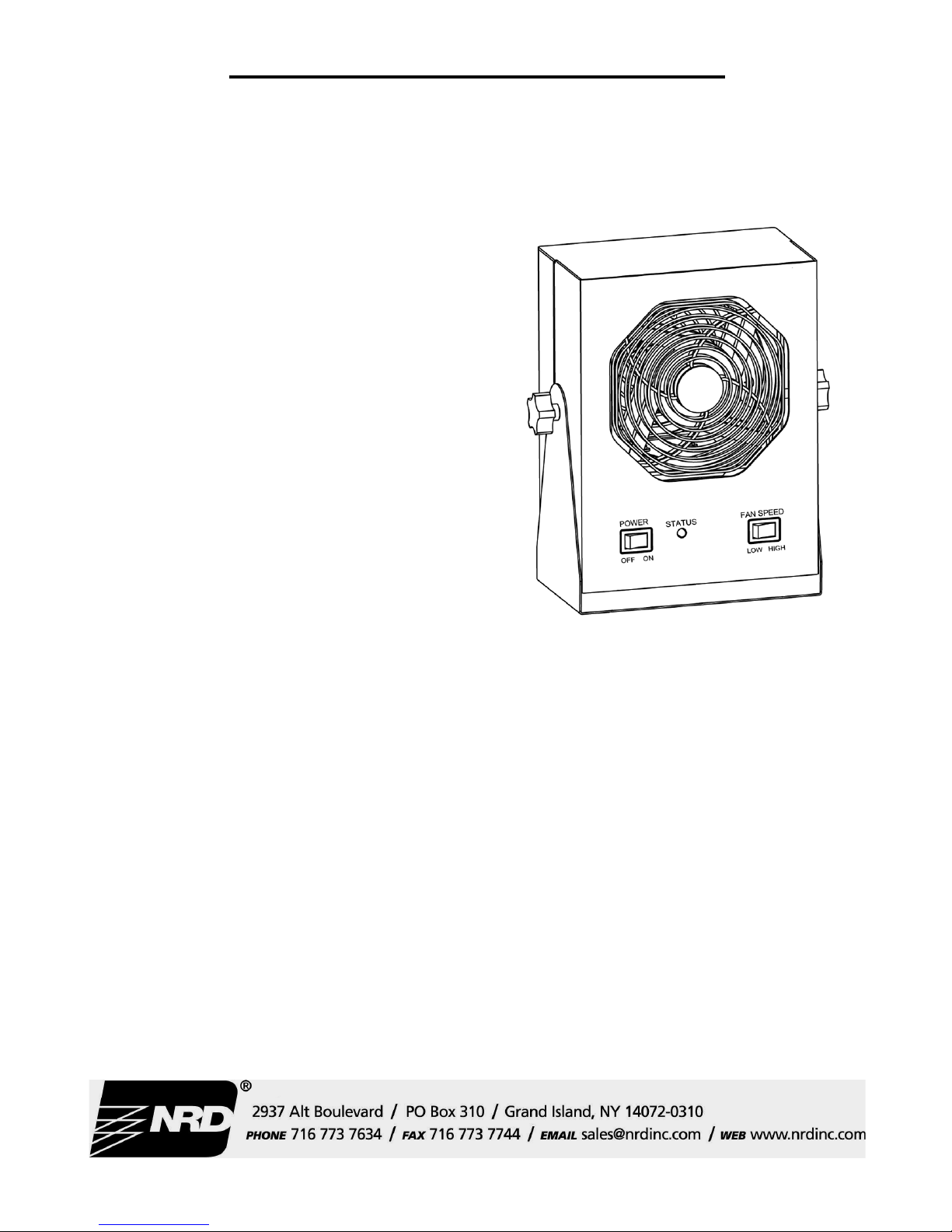
Sentinel Benchtop Ionizing Blower
Model 6210
Overview
The Sentinel Benchtop Ionizer utilizes DC high voltage to
generate balanced ionized airflow to eliminate static charges
on surfaces. The Ionizer can be placed at one end of the
workbench, wall or shelf mounted, and directed at the target
or area to be neutralized. The target’s neutralization time
will be optimal when placed 12” to 48” directly in front of
the Ionizer and will increase as the distance increases.
General Guidelines
• Keep water, oil, contamination and any fluids away
from the Ionizer at all times.
• Keep the Ionizer clean inside and out for optimal performance.
CAUTION: DISCONNECT THE IONIZER FROM
POWER BEFORE PERFORMING ANY MAINTENANCE, INSPECTION OR CLEANING TO AVOID
AN ELECTRICAL SHOCK HAZARD AND TO PREVENT DAMAGE TO THE IONIZER.
Contents
Remove the Ionizer from the carton and inspect for damage.
Included with the Ionizer should be:
• One (1) Sentinel Benchtop Ionizing Blower with Stand
and adjustment knobs installed.
• One (1) Detachable IEC Power cord (US 115V or 230V,
UK or Euro; must be specified at time of order).
• One (1) Round foam air filter with (1) ¾” round hook
fastener dot.
• This Installation, operation, and maintenance instruc-
tions sheet.
Installation
Locate the Ionizer 12” to 48” from the target to be neutralized for optimal performance, making sure that the airflow
will not be restricted. The Ionizer comes with a stand so that
it can be positioned on a flat surface, aimed at the target and
locked via adjustment knobs. It can also be wall or
shelf mounted to keep valuable bench space free for other
purposes and equipment. A working electrical outlet within
reach of the 6’ long detachable cord that is supplied with the
Ionizer will be required. The outlet must be a properly installed and grounded 3-prong outlet with supplied voltage to
match the Ionizer being installed. If one is not present, consider relocating the Ionizer to be within reach of an outlet or
having an electrical outlet installed near the Ionizer. Be sure
the ON/OFF switch, located on the front of the Ionizer, is in
the “OFF” position. Plug the power cord into the back of the
Ionizer and then into the appropriate AC power source.
IMPORTANT NOTE: Before powering up the Ionizer,
verify that the AC outlet is properly grounded and that the
supplied line voltage matches the electrical specification on
the label at the bottom of the Sentinel Benchtop Ionizer.
Plugging the Ionizer into an outlet with the incorrect voltage
may damage the Ionizer and will void any warranty coverage. The Ionizer must have a good ground to maintain
proper balance.
Page 2

INST6210 – 4/09
Installation / Operation / Maintenance
Sentinel Benchtop Ionizing Blower
Model 6210
Operation
Set the fan speed switch on the front of the Ionizer to the
LOW or HIGH position depending on the operator comfort
or desired decay time. Higher airflow will result in faster
static decay rates. Position the Ionizer so that the maximum
airflow is directed at the items or area to be neutralized.
Turn the Ionizer ON.
When the Ionizer is turned on, the “Status” LED will illuminate and remain GREEN, indicating that the Ionizer is
running normally. The audible alarm may chirp and the
“Status” LED may illuminate AMBER momentarily at
startup but it should return to normal/green mode in one second or less. If the Ionizer self test circuitry detects a fault
condition, the LED will illuminate and remain AMBER and
an audible alarm will sound.
Refer to the Troubleshooting section of this manual in the
case of a fault condition. There are no user serviceable parts
in this Ionizer. Routine cleaning is the only maintenance
that the user can perform.
Balance Adjustment
The Ionizer is an auto-balancing unit. However, tuning or
manual adjustment can be accomplished by inserting a small
flat screwdriver or trimmer adjustment tool into the tiny hole
for the balance adjustment potentiometer located at the bottom left corner on the back of the Ionizer. To increase the
output of positive ions, turn the potentiometer in a clockwise
direction. Conversely, to increase the output of negative
ions, turn the potentiometer in a counterclockwise direction.
Ideally the Ionizer will produce equal numbers of positive
and negative ions. Use a calibrated Charge Plate Monitor to
verify balanced operation of the Ionizer. Do not attempt
balance adjustment without a Charge Plate Monitor.
Maintenance / Alarms
Under normal conditions, the Ionizer will attract dirt and dust
(especially on the emitter pin electrodes). To maintain optimum neutralization efficiency and operation, cleaning
should be performed on a regular basis, once a month is recommended. In addition to improving decay time, cleaning
also keeps the Ionizer balanced without the need for adjustment.
NOTE: The AC power cord MUST be disconnected before
the Ionizer can be disassembled for maintenance. First, turn
the Ionizer OFF and unplug the power cord. Remove the
back cover by disengaging the four (4) screws on the back.
The emitter pin electrodes should be cleaned using a Q-Tip
type cotton swab or a soft nylon toothbrush dampened with
isopropyl alcohol. Clean the blades of the fan and the back
of the balance-sensing grill in front of the fan as much as is
accessible from the back of the Ionizer.
Use caution when cleaning inside the Ionizer. The emitter pin electrodes are sharp.
After cleaning the emitter pin electrodes, reattach the back
cover using the four (4) screws. Plug in the power cord and
turn the Ionizer back ON.
A filter has been provided for applications and/or environments outside of the Cleanroom and Medical Industries. It is
strongly recommended that industrial manufacturing type
users install the filter onto the back grill using the ¾” round
hook fastener dot (included with the Ionizer) to keep the
inside of the Ionizer clean. This filter should be changed
every 2 – 4 weeks, or as needed per a visual inspection.
Replacement emitter pin electrodes can be ordered from the
factory. Eight (8) emitter pins are required per Ionizer.
Neutralization (Decay) Times
The comparative efficiency of benchtop ionizers is determined by a standard test published by the ESD Association:
Standard S3.1. Positive and negative decay times (from
1000 volts to 100 volts) are measured in tenths of a second
using this standard. This test was performed with the Ionizer
positioned as shown, with the fan speed on high, and without
a filter. Decay times are as shown.
NOTE: Unauthorized servicing or modifications to your
Ionizer will void the product warranty and may create dangerous conditions. Servicing should be performed only at
the factory, or by a factory approved technician.
Page 3

INST6210 – 4/09
Installation / Operation / Maintenance
Sentinel Benchtop Ionizing Blower
Model 6210
Troubleshooting
The internal state-of-the-art circuitry of the Sentinel Blower
monitors the ion balance of the air exiting the blower, maintaining optimal offset voltage (balance) to protect ESD
sensitive components and products. If the circuit detects an
offset in the ion balance due to dirty emitter pins or other
conditions, it manipulates the output of the internal DC high
voltage power supplies to compensate for the offset and correct the condition. When the Ionizer status light is green, the
system is functioning properly and sensing balanced ionization. When the status light turns amber an audible alarm
sounds warning of a “fault” condition, which can usually be
resolved easily by the end user.
To troubleshoot a fault condition, follow these steps:
• Turn the switch to “OFF”.
• Remove the power cord from the back of the Ionizer.
• Using a small, soft nylon (or similar) bristle brush,
lightly dampened in isopropyl alcohol (not more than
70% solution), clean the eight (8) stainless steel emitter
electrode pins, the fan blades and the internal sensing
grill from the back side of the Ionizer to remove any dirt
or dust. A toothbrush can be used if the back cover is
removed from the Ionizer but power must be disconnected from the Ionizer before opening up the chassis to
prevent an electrical shock hazard. If available, blow
out the Ionizer with compressed air to clean it out and to
dry the alcohol before powering back up.
• Reconnect to power and turn the Ionizer on.
If the alarm condition persists, adjust the balance of the Ionizer using the small potentiometer screw accessed through
the tiny hole at the bottom left corner at the back of the Ionizer. This should only be done by an experienced technician
using proper equipment and procedures as specified in the
EOS/ESD-S3.1-1991 Standard. NRD LLC can calibrate and
certify the Ionizer performance for a nominal fee. If unable
to correct a fault condition, the Ionizer must be returned prepaid to the factory for evaluation, repair and/or calibration.
Contact NRD for a Return Authorization number and shipping address.
IMPORTANT NOTE: In some cases, if the balancesensing grill inside the blower becomes contaminated, the
Ionizer may not be able to detect an out-of-balance condition
and may continue to run in a “green light” status.
The presence of contamination on the backside (the side
nearest the fan) of the balance-sensing grill can cause the
Ionizer to overcompensate due to a false reading of the balance. Keeping the Ionizer clean as recommended in the
Maintenance section of this manual will help insure optimal
performance from your Sentinel Blower. A filter has been
provided for applications and/or environments outside of the
Cleanroom and Medical Industries. It is strongly recommended that industrial manufacturing type users install the
filter onto the back grill using the ¾” round hook fastener
dot (included with the Ionizer) to keep the inside of the Ionizer clean. This filter should be changed every 2 – 4 weeks,
or as needed per visual inspection.
Contact NRD for service, replacement filters, parts information and pricing.
Limited Warranty
NRD expressly warrants that for a period of one (1) year
from the time of purchase, the Ionizer will be free of defects
in material (parts) and workmanship (labor). Within the
warranty period, the Ionizer will be tested, repaired, or replaced at discretion of NRD, free of charge. Any Ionizer
under warranty should be shipped prepaid to the NRD factory. Call Customer Service at (716) 773-7634 for a Return
Authorization number and shipping instructions. Include a
copy of your original packing slip, invoice, or other proof of
purchase date.
If the Ionizer is out of warranty, NRD LLC will quote repair
charges necessary to bring your Ionizer up to factory standards.
Warranty Exclusions
The forgoing express warranty is made in lieu of all other
product warranties, expressed and implied, including merchantability and fitness for a particular purpose that is
specifically disclaimed. The express warranty will not apply
to defects or damage due to accidents, neglect, misuse, alterations, operator error, or failure to properly maintain, clean
or repair products.
Limit of Liability
The user shall determine the suitability of the product
for their intended use, and the user assumes all risk and
liability whatsoever in connection therein.
Page 4
INST6210 – 4/09
Installation / Operation / Maintenance
Sentinel Benchtop Ionizing Blower
Model 6210
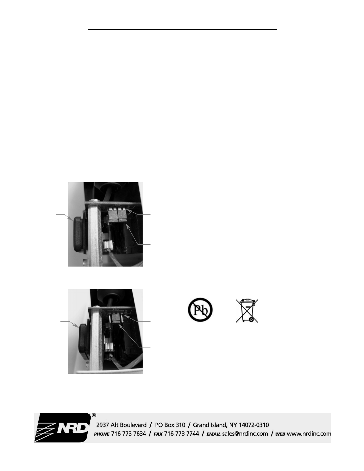
Changing Voltage
The input power voltage should be set to your specification
as ordered and prior to shipping. It is marked on the box
label and the specification label affixed to the bottom of the
Ionizer. The voltage can be reset to a different AC voltage
by removing the back of the case. NOTE: The AC power
cord MUST always be disconnected before the Ionizer is
disassembled. Reconfigure the voltage jumpers as shown in
the diagram(s) below to match your AC line voltage supply.
Input voltage is selected with the two internal jumpers as
shown below:
115 volt Jumper Settings
230 volt Jumper Settings
Specifications
Air Velocity: Two speed fan (250 lfpm with fan on high
speed).
Balance: ± 3 volt typical
(Temperature range: 65°F to 80°F,
Relative humidity: 15% to 65%)
Ion Emission: Steady state DC with sensor feedback.
Emitter Pin Electrodes: .050” diameter 316 stainless steel;
8 required.
High Voltage Power Supply: 5.5 kV DC nominal;
(1) positive HVDC and (1) negative HVDC
Input Power: AC line power, internally selectable for
100/120 VAC, 50/60 Hz, 1 phase or
200/240 VAC, 50/60 Hz, 1 phase
Fuse: 250 mA slow blow; located at AC inlet inside
rear cover; 2 required
Chassis: Powder coated aluminum or steel housing
Weight: 7.0 lbs. With cord; 7.4 lbs. Shipping weight with
Packaging
Dimensions: Width: 6.76” (8.08” with knobs)
Height: 9.82” (with stand)
Deep: 3.77”
Mounting: Bench top tilt adjust frame with locking knobs;
can also be wall or shelf mounted.
Ozone: Less than 0.005 ppm
Power
Jack
Voltage
Selection
Header
Jumpers
Power
Jack
Jumper
Voltage
Selection
Header
 Loading...