

Page 1

7550 Independence Drive
Walton Hills, OH 44146-5541
Phone (440) 232-7900
Toll-free (800) 225-4379
Fax (440) 232-6294
"Use Genuine NPK Parts”
U and G-SERIES SECONDARY
CONCRETE CRUSHERS
MODELS U21J, U21JR, U31J, U31JR
U45J, U45JR, G7, G18J, G26J, G30JR
OPERATION AND MAINTENANCE MANUAL
© Copyright 2018 NPK Construction Equipment, Inc. www.npkce.com U000-9600B U and
G Series Crushers Operation Manual 10-18
Page 2

CONTENTS
SAFETY .................................................................................................................................................. 3
OPERATION ...................................................................................................................................... 4
MAINTENANCE ................................................................................................................................. 5
INTRODUCTION ..................................................................................................................................... 7
EXCAVATOR COMPATIBILITY ............................................................................................................... 7
MODEL SPECIFICATIONS ..................................................................................................................... 8
SERIAL NUMBER LOCATION .............................................................................................................. 20
U21J/JR, U31J/JR, U45J/JR ............................................................................................................. 20
G7, G18J, G26J ................................................................................................................................ 21
G30JR .............................................................................................................................................. 22
CRUSHER BOOSTER & CYLINDER ..................................................................................................... 23
INTRODUCTION .............................................................................................................................. 23
STRUCTURE OF THE BOOSTED CYLINDER .................................................................................. 24
OPERATING PRINCIPLE ................................................................................................................. 25
HYDRAULIC INSTALLATION ................................................................................................................ 32
HYDRAULIC KITS ............................................................................................................................ 32
FLOW DIRECTION ........................................................................................................................... 32
SHUT-OFF VALVES ......................................................................................................................... 33
TEST PORT LOCATIONS ................................................................................................................ 33
PREVENTION OF CONTAMINATION .............................................................................................. 35
HYDRAULIC QUICK DISCONNECTS ............................................................................................... 36
MOUNTING INSTALLATION ................................................................................................................. 38
MOUNTING TO THE CARRIER ........................................................................................................ 39
REMOVAL FROM THE CARRIER .................................................................................................... 40
STORAGE OF THE CRUSHER ............................................................................................................. 40
HOSE INSTALLATION .......................................................................................................................... 41
WHIP HOSE INSTALLATION TIPS ................................................................................................... 41
OPERATING INSTRUCTIONS .............................................................................................................. 43
OPERATING TECHNIQUES AND PRECAUTIONS ............................................................................... 45
GENERAL MAINTENANCE ................................................................................................................... 48
DAILY INSPECTION AND MAINTENANCE ...................................................................................... 48
LUBRICATION POINTS.................................................................................................................... 49
HOSE INSTALLATION TIPS ............................................................................................................. 51
CUTTER BLADE MAINTENANCE .................................................................................................... 53
JAW INSPECTION AND MAINTENANCE.............................................................................................. 56
WEEKLY INSPECTION .................................................................................................................... 56
MINIMUM DISTANCE BETWEEN FIXED AND MOVEABLE JAW ...................................................... 56
TEETH MAINTENANCE AND REPLACEMENT .................................................................................. 58
MOVEABLE JAW BUILDUP AND HARDFACING ............................................................................... 58
TEETH REPLACEMENT .................................................................................................................. 59
REPLACEABLE TOOTH PLATES – MOVEABLE JAWS ................................................................... 60
REPLACEABLE TOOTH PLATES – MAIN FRAME ........................................................................... 60
JAW AND TOOTH REBUILD PROCEDURE: ALL MODELS ............................................................. 61
JAW CONTACT AREAS ................................................................................................................... 63
MAIN FRAME REWORK GUIDE ........................................................................................................... 64
FRAME MAINTENANCE – REPAIR OF MAIN FRAME .......................................................................... 65
ROUTE WELD REPAIR .................................................................................................................... 65
INSPECTION AND MAINTENANCE ...................................................................................................... 67
BOOSTER CYLINDER ..................................................................................................................... 67
CYLINDER COMPONENTS ............................................................................................................. 70
REPAIR TOOLS AND EQUIPMENT.................................................................................................. 72
TOP BRACKET CONVERSION ............................................................................................................. 79
CONVERSION PACKAGES OFFERED FOR “U” SERIES CRUSHERS ............................................ 79
SLEWING RING INSPECTION AND MAINTENANCE ........................................................................... 80
MEASURING MAXIMUM AXIAL MOVEMENT................................................................................... 80
ROTATION BEARING OUTER DIRT SEAL REPLACEMENT ............................................................ 81
CRUSHER RELIEF LOCATIONS .......................................................................................................... 81
1
Page 3

CONTENTS
U21J, U21JR, U31J, U31JR, U45J, U45JR, G30JR ........................................................................... 82
G7, G18J, G26J ................................................................................................................................ 82
SWIVEL MANIFOLD MAINTENANCE ................................................................................................... 84
SWIVEL MANIFOLD ASSEMBLY ..................................................................................................... 84
LEAKAGE OF THE SEALS ............................................................................................................... 84
TESTING THE SWIVEL SEALS FOR INTERNAL LEAKAGE ............................................................. 84
REPLACEMENT OF THE SEALS IN THE SWIVEL ........................................................................... 85
FASTENER TORQUE SPECIFICATIONS ............................................................................................. 88
HOSE TORQUE SPECIFICATIONS ...................................................................................................... 95
JIC ENDS ......................................................................................................................................... 95
ORFS ENDS .................................................................................................................................... 95
TROUBLESHOOTING ........................................................................................................................... 96
RELIEF VALVE LOCATION ............................................................................................................ 102
KEYWORDS FOR COMMON CRUSHER COMPONENTS .................................................................. 116
KEYWORDS FOR COMMON CRUSHER CYLINDER COMPONENTS ............................................... 117
WARRANTY STATEMENTS ............................................................................................................... 118
2
Page 4

FALLING OR FLYING DEBRIS decal is included
with each NPK CONCRETE CRUSHER. The
decal (part number H100-7210) must be installed
in the cab, visible to the operator.
STAY CLEAR decal (part number H100-7200) is
installed on all NPK CONCRETE CRUSHERS,
Shears, and Material Processors. Keep them
clean and visible. NPK will provide decals free of
charge as needed.
SAFETY
Safety notices in NPK Instruction Manuals follow ISO and ANSI standards for
safety warnings:
DANGER (red) notices indicate an imminently hazardous situation
which, if not avoided, will result in death or serious injury.
WARNING (orange) notices indicate a potentially hazardous situation
which, if not avoided, could result in death or serious injury.
CAUTION (yellow) notices indicate a potentially hazardous situation,
which, if not avoided, may result in minor or moderate injury.
ATTENTION (blue) notices in NPK Instruction Manuals are an NPK
standard to alert the reader to situations which, if not avoided, could
result in equipment damage.
WARNING – FALLING OR FLYING DEBRIS decals are included with each NPK
CONCRETE CRUSHER. The decal must be installed in the cab, visible to the operator.
WARNING - STAY CLEAR decals are installed on all NPK CONCRETE CRUSHERS.
Keep them clean and visible. NPK will provide decals free of charge as needed.
3
Page 5

Warning Decal for Cab Installation
SAFETY
OPERATION
1. Operator personnel must read and understand the NPK INSTRUCTION MANUAL
to prevent serious or fatal injury.
2. FLYING OR FALLING DEBRIS CAN CAUSE SERIOUS OR FATAL INJURY.
Keep personnel and bystanders clear of the CONCRETE CRUSHER while in
operation.
3. Do not operate CONCRETE CRUSHER without
an impact resistant shield between the
CONCRETE CRUSHER and operator. Operate
with extreme caution near walls or columns that
may collapse and near concrete and debris that
may fall.
4. Operate the CONCRETE CRUSHER from the
operator’s seat only.
5. Use two people whenever operator visibility is
limited, one to operate the CONCRETE
CRUSHER, the other to guide operations.
6. Do not leave a load suspended in air.
7. Do not pass a load over people, vehicles, etc.
8. Do not operate the CONCRETE CRUSHER
within reach of power lines.
9. Do not climb, sit, or ride on the CONCRETE CRUSHER.
10. Match the CONCRETE CRUSHER size to excavator according to NPK
recommendations. The excavator must be stable during CONCRETE CRUSHER
operation and during transport. See CARRIER COMPATIBILITY section of the
NPK instruction manual.
11. Do not operate without inspection (access) covers in place.
12. Be especially cautious around hydraulic lines. Hydraulic oil can be extremely HOT!
Avoid skin contact with hydraulic oil. It can cause severe burns!
13. Protect hands and body from hydraulic fluids under pressure. Escaping high
pressure fluid can penetrate the skin, causing serious injury. Avoid the hazard by
relieving pressure before disconnecting any lines. Search for leaks with a piece of
cardboard, or other object. If an accident occurs, see a doctor immediately!
Hydraulic fluid injected into the skin must be surgically removed within a few hours
or gangrene may result.
14. The pressure generated by the power intensifier on the CONCRETE CRUSHER
exceeds 10,000 psi (690 bar), which is higher than commonly encountered on
hydraulic equipment. To avoid bodily harm and/or injury when conducting
inspection checks, use gauges, hoses and fittings rated at 15,000 psi (1035 bar).
For parts replacement, use only genuine NPK replacement parts. Contact NPK
Service Department at 1-800-225-4379.
15. When removing or installing mounting pins, beware of flying metal chips.
4
Page 6
SAFETY
MAINTENANCE
1. Use only NPK supplied replacement parts. NPK specifically disclaims any
responsibility for bodily injury or CONCRETE CRUSHER damage that results from
the use of parts not sold or approved by NPK.
2. Use extreme caution in handling. A fully assembled CONCRETE CRUSHER can
weigh up to 5 tons (4-1/2 tonnes). Sub-assemblies range in weight from hundreds
to thousands of pounds. To avoid bodily harm, use lifting and securing
mechanisms of adequate capacity to support loads. Seek the aid of an assistant
as much as possible, and always when handling heavier sub-assemblies.
3. Use extreme caution when changing jaw sets, particularly in the field. Employ
lifting and securing mechanisms of adequate capacity to support the jaw sets. At
least two people are required to change a jaw set safely in the field.
4. Wear safety glasses and protective clothing when working on the CONCRETE
CRUSHER. Wear thermal-protective gloves when handling heated parts.
5. Prevent exposure to hazardous fumes. Remove all paint, grease, and oil before
heating, cutting, or welding on the CONCRETE CRUSHER.
6. Be especially cautious around hydraulic lines. Hydraulic oil can be extremely HOT!
Avoid skin contact with hydraulic oil. It can cause severe burns!
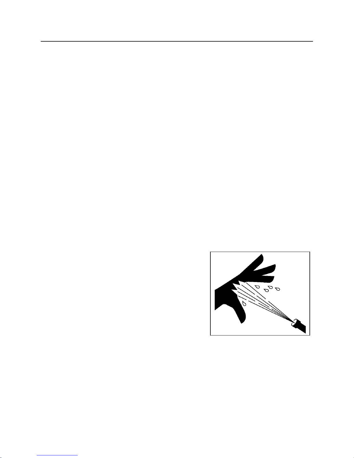
7. Protect hands and body from hydraulic
fluids under pressure. Escaping fluid under
pressure can penetrate the skin, causing
serious injury. Avoid the hazard by relieving
pressure before disconnecting any lines.
Search for leaks with a piece of cardboard, or
other object. If an accident occurs, see a
doctor immediately! Hydraulic fluid injected
into the skin must be surgically removed
within a few hours or gangrene may result!
8. The pressure generated by the power intensifier on the CONCRETE CRUSHER
exceeds 10,000 psi (690 bar), which is higher than commonly encountered on
hydraulic equipment. To avoid bodily harm and/or injury when conducting
inspection checks, use gauges, hoses and fittings rated at 15,000 psi (1035 bar).
For parts replacement, use only genuine NPK replacement parts. Contact NPK
Service Department at 1-800-225-4379.
9. When removing or installing mounting pins, beware of flying metal chips.
5
Page 7

ATTENTION
SAFETY
MAINTENANCE
STANDARD PRACTICES
Maintenance of and repairs to the CONCRETE CRUSHER should be performed by an
experienced service technician, thoroughly familiar with all standard practices and
procedures, and most importantly, all safety precautions. The following is a review of
common standard practices to be followed when working with hydraulic equipment, and
is not meant to be all-inclusive. Rather, this review is presented as a reminder as to
some of the unique characteristics of hydraulic equipment.
The prevention of foreign contaminant damage is critical when working with
hydraulic equipment. Protect exposed holes and parts to guard against entry of
foreign contaminants. Thoroughly clean the work area.
Mark the location and position of mating parts as an aid to re-assembly. Mark
corresponding parts uniquely to reflect their relationship, including proper location,
position, orientation, and/or alignment.
DO:
During assembly, observe all markings made during disassembly, and all
corresponding features of mating parts to ensure proper location, position,
orientation, and alignment.
During disassembly of a sub-assembly, place removed components on a clean, dry
surface, in proper relative position as an aid in re-assembly.
Always inspect threaded areas on components. Repair or replace as required.
Use care to avoid scratches, nicks, dents, or other damage to machined surfaces of
mating components.
When securing a component, always tighten cap screws gradually in an opposing
pattern, applying the specified torque.
Grease can be used to temporarily hold a part in place while the abutting part is
placed into position.
Always use common sense and exercise standard safety precautions when working
with all tools and equipment required to maintain, repair or troubleshoot the
CONCRETE CRUSHER.
6
Page 8
CRUSHER
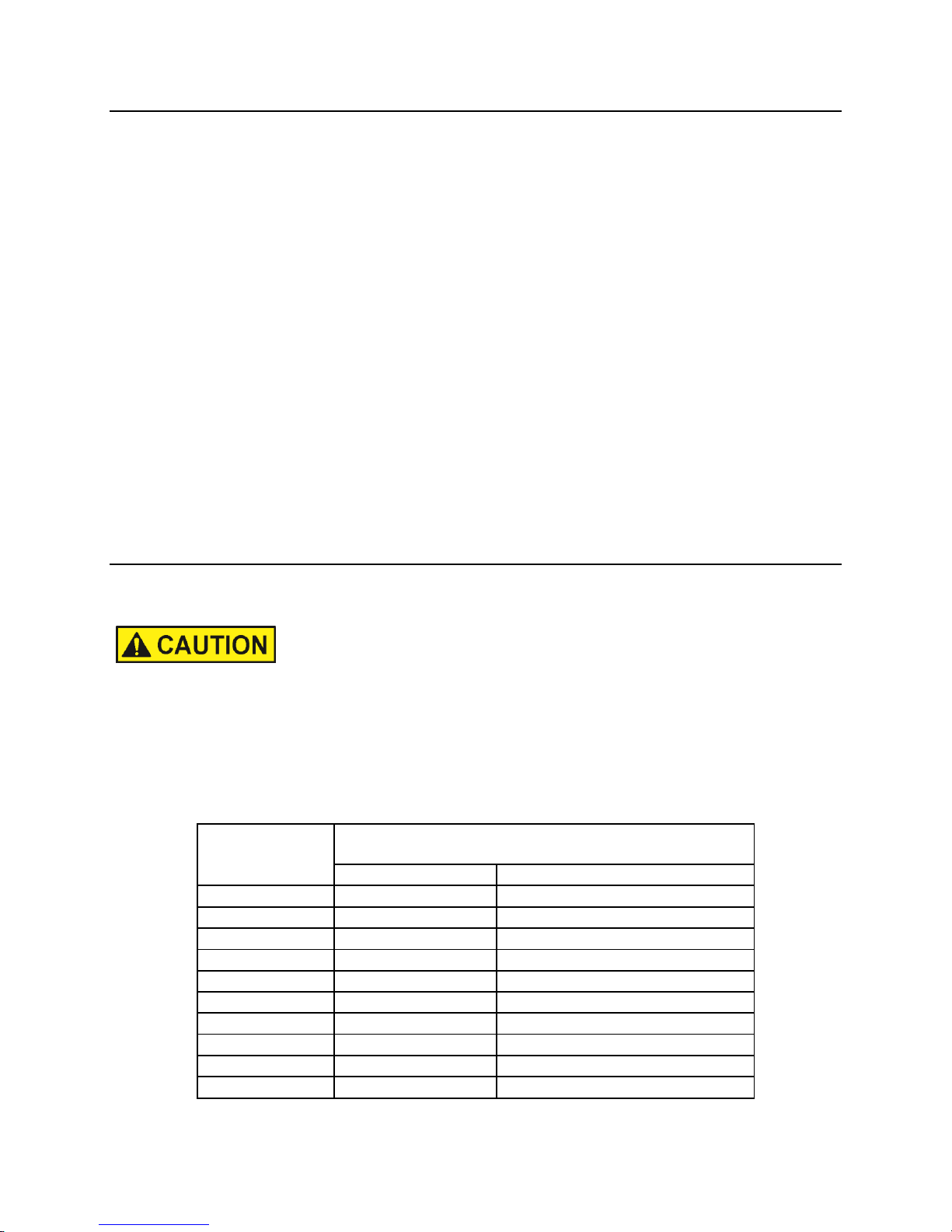
RECOMMENDED CARRIER WEIGHT RANGE
MODEL
3rd member mounting
US ton
(Metric ton)
U21J
21 - 31
(19 - 28)
U21JR
21 - 31
(19 - 28)
U31J
31 - 53
(28 - 48)
U31JR
31 - 53
(28 - 48)
U45J
45 - 55
(41 - 50)
U45JR
45 - 55
(41 - 50)
G7
6.6 - 11
(6 - 10)
G18J
20 - 25
(18 - 23)
G26J
25 - 35
(23 - 32)
G30JR
35 - 50
(32 - 45)
Specifications subject to change without notice.
INTRODUCTION
Thank you for your purchase of an NPK attachment. NPK prides itself in the design and
manufacture of high quality attachments. The quality workmanship and materials,
which go into all of our attachments, will provide maximum service life. With proper
care, and use, your NPK attachment should provide you with many years of productive
service.
The purpose of this manual is to provide you with information and instructions required
to properly operate and maintain the CONCRETE CRUSHER. This will result in
maximum ATTACHMENT reliability and productivity.
Read this manual thoroughly before attempting to operate, remove, disassemble,
repair, or troubleshoot the CONCRETE CRUSHER or any of its components. For
additional information or help with any problem encountered, please contact your
authorized NPK dealer.
Follow all the safety precautions contained in this manual. Failure to follow safety
precautions can result in death, personal injury, injury to others and property
damage.
Use replacement parts sold by NPK only. NPK is not responsible for failures resulting
from alterations not approved by NPK or substitution of parts not sold by NPK.
EXCAVATOR COMPATIBILITY
These carrier weight ranges are intended as a guideline only. Other factors, such as
stick length, counterweights, undercarriage, etc., must be taken into consideration.
Mounting a CONCRETE CRUSHER that is too heavy for the carrier can be dangerous
and damage the carrier. Verify carrier stability with the CONCRETE CRUSHER before
transport or operation.
Mounting a CONCRETE CRUSHER that is too small for the carrier can damage the
CONCRETE CRUSHER and void warranties. Please consult NPK Service or
Engineering for specific detailed information.
7
Page 9
MODEL
Weight
Maximum Jaw
Oil Flow
Cycle Time
Opening
(seconds)
lb.
(kg)
in.
(mm)
gpm
(lpm)
open
close
U21J
4,650
(2,110)
31.6
(802.4)
26-53
(98-200)
1.2
1.6
MODEL
Maximum
Crushing Force
Crushing Force
Operating
Pressure
at d86
at d87
US
(Metric
US
(Metric
psi
(bar)
Ton
Ton)
Ton
Ton)
U21J
3,771
(260)
73
(66)
100
(90)
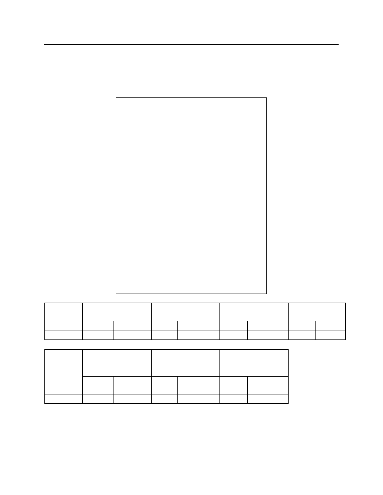
MODEL SPECIFICATIONS
U21J SECONDARY
CONCRETE CRUSHER
Specifications subject to change without notice.
Cycle time is full stroke at maximum flow.
Carrier flow is set at minimal operating pressure of 1000 psi (69 bar).
*Maximum operating pressure is determined by reliefs in the crusher.
8
Page 10
MODEL
Weight
Maximum Jaw
Oil Flow
Cycle Time
Opening
(seconds)
lb.
(kg)
in.
(mm)
gpm
(lpm)
open
close
U21JA
4,650
(2,110)
31.6
(802.4)
26-53
(98-200)
1.2
1.6
MODEL
Maximum
Crushing Force
Crushing Force
Operating
Pressure
at d86
at d87
US
(Metric
US
(Metric
psi
(bar)
Ton
Ton)
Ton
Ton)
U21JA
3,771
(260)
73
(66)
100
(90)
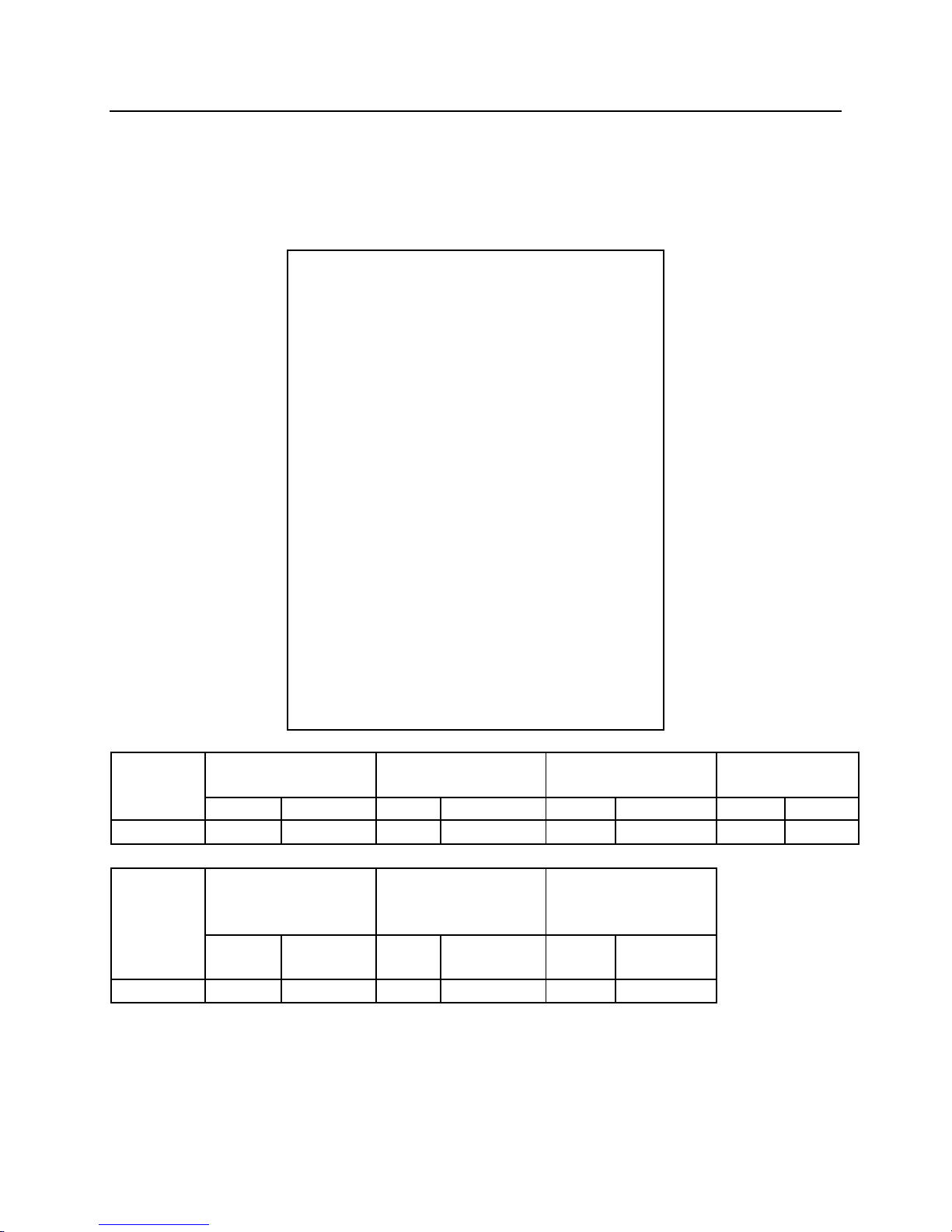
MODEL SPECIFICATIONS
U21JA SECONDARY
CONCRETE CRUSHER
Specifications subject to change without notice.
Cycle time is full stroke at maximum flow.
Carrier flow is set at minimal operating pressure of 1000 psi (69 bar).
*Maximum operating pressure is determined by reliefs in the crusher.
9
Page 11
MODEL
Weight
Maximum Jaw
Oil Flow
Cycle Time
Opening
(seconds)
lb.
(kg)
in.
(mm)
gpm
(lpm)
open
close
U21JR
5,400
(2,500)
31.6
(802.4)
26-53
(98-200)
1.2
1.6
MODEL
Maximum
Crushing Force
Crushing Force
Operating
Pressure
at d86
at d87
US
(Metric
US
(Metric
psi
(bar)
Ton
Ton)
Ton
Ton)
U21JR
3,771
(260)
73
(66)
100
(90)
MODEL SPECIFICATIONS
U21JR SECONDARY
CONCRETE CRUSHER
Specifications subject to change without notice.
Cycle time is full stroke at maximum flow.
Carrier flow is set at minimal operating pressure of 1000 psi (69 bar).
*Maximum operating pressure is determined by reliefs in the crusher.
10
Page 12
MODEL
Weight
Maximum Jaw
Oil Flow
Cycle Time
Opening
(seconds)
lb.
(kg)
in.
(mm)
gpm
(lpm)
open
close
U31J
7,000
(3,175)
38.6
(980)
26-66
(98-250)
2.4
2.9
MODEL
Maximum
Crushing Force
Crushing Force
Operating
Pressure
at d86
at d87
US
(Metric
US
(Metric
psi
(bar)
Ton
Ton)
Ton
Ton)
U31J
4,061
(280)
130
(118)
173
(157)
MODEL SPECIFICATIONS
U31J SECONDARY
CONCRETE CRUSHER
Specifications subject to change without notice.
Cycle time is full stroke at maximum flow.
Carrier flow is set at minimal operating pressure of 1000 psi (69 bar).
*Maximum operating pressure is determined by reliefs in the crusher.
11
Page 13
MODEL
Weight
Maximum Jaw
Oil Flow
Cycle Time
Opening
(seconds)
lb.
(kg)
in.
(mm)
gpm
(lpm)
open
close
U31JA
7,000
(3,175)
38.6
(980)
26-66
(98-250)
2.4
2.9
MODEL
Maximum
Crushing Force
Crushing Force
Operating
Pressure
at d86
at d87
US
(Metric
US
(Metric
psi
(bar)
Ton
Ton)
Ton
Ton)
U31JA
4,061
(280)
130
(118)
173
(157)
MODEL SPECIFICATIONS
U31JA SECONDARY
CONCRETE CRUSHER
Specifications subject to change without notice.
Cycle time is full stroke at maximum flow.
Carrier flow is set at minimal operating pressure of 1000 psi (69 bar).
*Maximum operating pressure is determined by reliefs in the crusher.
12
Page 14
MODEL
Weight
Maximum Jaw
Oil Flow
Cycle Time
Opening
(seconds)
lb.
(kg)
in.
(mm)
gpm
(lpm)
open
close
U31JR
8,000
(3,630)
38.6
(980)
26-66
(98-250)
2.4
2.9
MODEL
Maximum
Crushing Force
Crushing Force
Operating
Pressure
at d86
at d87
US
(Metric
US
(Metric
psi
(bar)
Ton
Ton)
Ton
Ton)
U31JR
4,061
(280)
130
(118)
173
(157)
MODEL SPECIFICATIONS
U31JR SECONDARY
CONCRETE CRUSHER
Specifications subject to change without notice.
Cycle time is full stroke at maximum flow.
Carrier flow is set at minimal operating pressure of 1000 psi (69 bar).
*Maximum operating pressure is determined by reliefs in the crusher.
13
Page 15
MODEL
Weight
Maximum Jaw
Oil Flow
Cycle Time
Opening
(seconds)
lb.
(kg)
in.
(mm)
gpm
(lpm)
open
close
U45J
9,000
(4,080)
44.5
(1130)
46-73
(175-275)
2.4
3.0
MODEL
Maximum
Crushing Force
Crushing Force
Operating
Pressure
at d86
at d87
US
(Metric
US
(Metric
psi
(bar)
Ton
Ton)
Ton
Ton)
U45J
4,350
(300)
142
(129)
195
(177)
MODEL SPECIFICATIONS
U45J SECONDARY
CONCRETE CRUSHER
Specifications subject to change without notice.
Cycle time is full stroke at maximum flow.
Carrier flow is set at minimal operating pressure of 1000 psi (69 bar).
*Maximum operating pressure is determined by reliefs in the crusher.
14
Page 16
MODEL
Weight
Maximum Jaw
Oil Flow
Cycle Time
Opening
(seconds)
lb.
(kg)
in.
(mm)
gpm
(lpm)
open
close
U45JR
9,920
(4,500)
44.5
(1130)
46-73
(175-275)
2.4
3.0
MODEL
Maximum
Crushing Force
Crushing Force
Operating
Pressure
at d86
at d87
US
(Metric
US
(Metric
psi
(bar)
Ton
Ton)
Ton
Ton)
U45JR
4,350
(300)
142
(129)
195
(177)
MODEL SPECIFICATIONS
U45JR SECONDARY
CONCRETE CRUSHER
Specifications subject to change without notice.
Cycle time is full stroke at maximum flow.
Carrier flow is set at minimal operating pressure of 1000 psi (69 bar).
*Maximum operating pressure is determined by reliefs in the crusher.
15
Page 17
MODEL
Weight
Maximum Jaw
Oil Flow
Cycle Time
Opening
(seconds)
lb.
(kg)
in.
(mm)
gpm
(lpm)
open
close
G7
1,650
(750)
21
(533.4)
13-21
(49-80)
0.9
1.8
MODEL
Maximum
Crushing Force
Crushing Force
Operating
Pressure
at d86
at d87
US
(Metric
US
(Metric
psi
(bar)
Ton
Ton)
Ton
Ton)
G7
3,000
(206)
39
(35)
52
(47)
MODEL SPECIFICATIONS
G7 SECONDARY
CONCRETE CRUSHER
Specifications subject to change without notice.
Cycle time is full stroke at maximum flow.
Carrier flow is set at minimal operating pressure of 1000 psi (69 bar).
*Maximum operating pressure is determined by reliefs in the crusher.
16
Page 18
MODEL
Weight
Maximum Jaw
Oil Flow
Cycle Time
Opening
(seconds)
lb.
(kg)
in.
(mm)
gpm
(lpm)
open
close
G18J
4,400
(2000)
33
(838.2)
26-52
(98-197)
1.8
2.1
MODEL
Maximum
Crushing Force
Crushing Force
Operating
Pressure
at d86
at d87
US
(Metric
US
(Metric
psi
(bar)
Ton
Ton)
Ton
Ton)
G18J
3,700
(255)
72
(65)
93
(84)
MODEL SPECIFICATIONS
G18J SECONDARY
CONCRETE CRUSHER
Specifications subject to change without notice.
Cycle time is full stroke at maximum flow.
Carrier flow is set at minimal operating pressure of 1000 psi (69 bar).
*Maximum operating pressure is determined by reliefs in the crusher.
17
Page 19
MODEL
Weight
Maximum Jaw
Oil Flow
Cycle Time
Opening
(seconds)
lb.
(kg)
in.
(mm)
gpm
(lpm)
open
close
G26J
6,050
(2745)
36
(965.2)
26-66
(98-250)
1.8
3.2
MODEL
Maximum
Crushing Force
Crushing Force
Operating
Pressure
at d86
at d87
US
(Metric
US
(Metric
psi
(bar)
Ton
Ton)
Ton
Ton)
G26J
4,000
(275)
109
(99)
150
(136)
MODEL SPECIFICATIONS
G26J SECONDARY
CONCRETE CRUSHER
Specifications subject to change without notice.
Cycle time is full stroke at maximum flow.
Carrier flow is set at minimal operating pressure of 1000 psi (69 bar).
*Maximum operating pressure is determined by reliefs in the crusher.
18
Page 20
MODEL
Weight
Maximum Jaw
Oil Flow
Cycle Time
Opening
(seconds)
lb.
(kg)
in.
(mm)
gpm
(lpm)
open
close
G30JR
7,000
(3175)
36
(965.2)
26-66
(98-250)
1.8
3.2
MODEL
Maximum
Crushing Force
Crushing Force
Operating
Pressure
at d86
at d87
US
(Metric
US
(Metric
psi
(bar)
Ton
Ton)
Ton
Ton)
G30JR
4,000
(275)
109
(99)
150
(136)
MODEL SPECIFICATIONS
G30JR SECONDARY
CONCRETE CRUSHER
Specifications subject to change without notice.
Cycle time is full stroke at maximum flow.
Carrier flow is set at minimal operating pressure of 1000 psi (69 bar).
*Maximum operating pressure is determined by reliefs in the crusher.
19
Page 21

SERIAL NUMBER LOCATION
U21J/JR, U31J/JR, U45J/JR
20
Page 22

SERIAL NUMBER LOCATION
G7, G18J, G26J
21
Page 23

SERIAL NUMBER LOCATION
G30JR
22
Page 24
c11
Jaw Cylinder
c14
Booster Piston
c15
Main Valve Assembly
c16
Sequence Valve Cartridge
c17
Relief Valve (close)
c18
Relief Valve (open)
c44
Swivel Manifold
k2
Carrier Hydraulic Pump
k7
Carrier Control Valve
CRUSHER BOOSTER & CYLINDER
INTRODUCTION
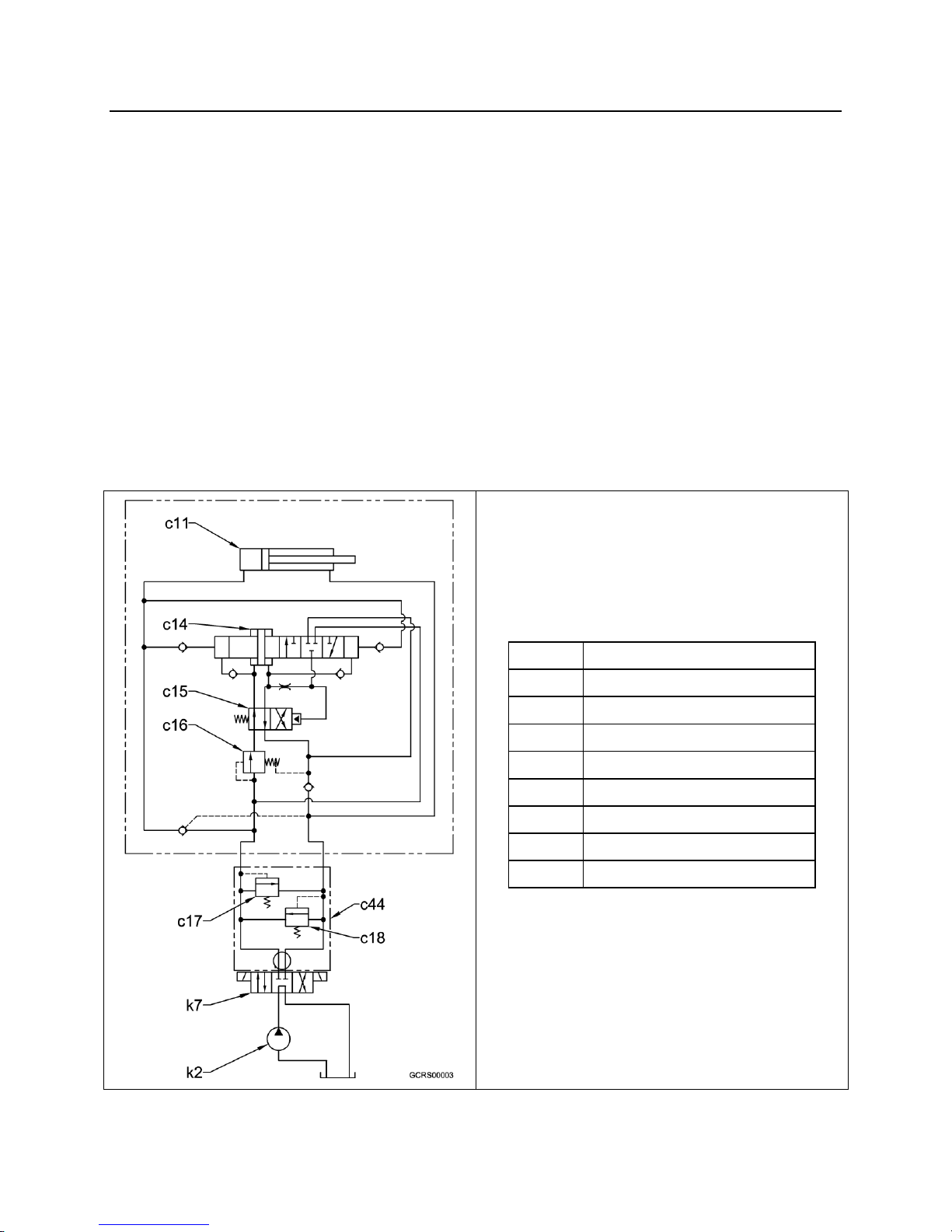
The hydraulic cylinder used on the NPK Crushers is equipped with a hydraulic booster.
To close the jaws of the crusher, hydraulic oil from the carrier is directed to the base
end of the cylinder, which extends the cylinder rod. Under no load, no boost is applied
and this results in a rapid cycle time as compared to large, non-boosted cylinders.
When a load (material to be crushed) is encountered, pressure builds and shifts the
sequence valve of the booster. This directs oil into the booster section, which
intensifies the pressure well beyond the system operating pressure of the excavator.
The compact NPK Boosted Cylinder System provides a working force equal to far larger
un-boosted cylinders, which are working at excavator system pressure. Because the
NPK boosted cylinders are smaller, they require less oil for full stroke as compared to
large diameter cylinders. This reduces cycle time for the NPK Crusher. To open the
jaws of the NPK Crusher, oil is directed to the rod end of the cylinder. This retracts the
rod and pulls the jaw open. No boost is provided in the jaw open mode.
23
Page 25

Fig. 1
As shown in Fig. 1, the booster cylinder
consists of:
c11
Jaw Cylinder
c14
Booster Piston
c15
Main Valve Assembly
c16
Sequence Valve Cartridge
c17
Relief Valve (close)
c18
Relief Valve (open)
c19
Plunger
c20
Pilot Check Valve Assembly
c21
Check Valve 1 - booster piston inner
"B"
c22
Check Valve 2 - booster piston inner
"A"
c23
Check Valve 3 - booster sleeve "B"
c24
Check Valve 4 - booster sleeve "A"
c25
Check Valve 5 - Return
c44
Swivel Manifold
k2
Carrier Hydraulic Pump
k7
Carrier Control Valve
v1
Oil Chamber - 1
v2
Oil Chamber - 2
v3
Oil Chamber - 3
v4
Oil Chamber - 4
CRUSHER BOOSTER & CYLINDER
STRUCTURE OF THE BOOSTED CYLINDER
For a complete breakdown of parts in the booster cylinder assembly, see the parts
manual for each unit by serial number.
24
Page 26
Fig. 2
CYLINDER EXTEND (NO LOAD)
c11
Jaw Cylinder
c20
Pilot Check Valve Assembly
k7
Carrier Control Valve
fl1
High Pressure Hydraulic Flow
fl2
Low Pressure Hydraulic Flow
fl3
Intensified Hydraulic Flow
When the cylinder (c11) is extended (jaw
close) and no load (material to be crushed)
is encountered, oil is directed from the
carrier control valve (k7) to the base end of
the cylinder by way of the pilot check valve
(c20) in the booster assembly. When
there is no load condition, hydraulic
pressure is low and no boosted pressure is
required.
CRUSHER BOOSTER & CYLINDER
OPERATING PRINCIPLE
25
Page 27
Fig. 3
BOOSTER ACTUATION
c14
Booster Piston
c15
Main valve Assembly
c16
Sequence Valve Cartridge
fl1
High pressure Hydraulic Flow
fl2
Low Pressure Hydraulic Flow
fl3
Intensified Hydraulic Flow
When a load (material to be crushed) is
encountered on jaw close, the hydraulic
pressure in the booster unit starts to rise.
When the hydraulic pressure reaches a
pre-set value, the sequence valve (c16)
shifts and directs oil through the control
valve (c15) of the booster, then to the
booster piston (c14). This starts the
boosting process. The booster piston is
double ended and provides boost in each
direction of booster piston travel.
CRUSHER BOOSTER & CYLINDER
OPERATING PRINCIPLE
26
Page 28
Fig. 4
FORWARD PISTON STROKE
c11
Jaw Cylinder
c14
Booster Piston
c15
Main Valve Assembly
c16
Sequence Valve Cartridge
c23
Check Valve 3 - booster sleeve "B"
c24
Check Valve 4 - booster sleeve "A"
v1
Oil Chamber - 1
v2
Oil Chamber - 2
v4
Oil Chamber - 4
fl1
High Pressure Hydraulic Oil
fl2
Low Pressure Hydraulic Oil
fl3
Intensified Hydraulic Oil
The hydraulic oil that has passed through the
sequence valve (c16) and booster valve (c15),
flows into rear oil chambers v1 and v2 of the
booster piston (c14) and strokes it toward oil
chamber v4. Because the area of the booster
piston in oil chamber v1 is greater than the
area in chamber v4, the pressure in oil
chamber v4 is intensified. The higher
pressure oil is pushed through check valve
(c24) to the base end of the cylinder (c11) and
closes check valve (c23).
CRUSHER BOOSTER & CYLINDER
OPERATING PRINCIPLE
27
Page 29
Fig. 5
MAIN VALVE REVERSE SHIFT
c14
Booster Piston
c15
Main Valve Assembly
c19
Plunger
c26
Port C1 Piston
c27
Port C2 Piston
fl1
High Pressure Hydraulic Flow
fl2
Low Pressure Hydraulic Flow
fl3
Intensified Hydraulic Flow
When the booster piston (c14) reaches its
full stroke, oil entering port “C1” (c26)
transfers to port “C2” (c27) of the piston.
Oil is also sent to the plunger (c19) end of
the main valve assembly (c15). This shifts
the valve as shown in Fig. 5.
CRUSHER BOOSTER & CYLINDER
OPERATING PRINCIPLE
28
Page 30
Fig. 6
REVERSE PISTON STROKE
c11
Jaw Cylinder
c14
Booster Piston
c15
Main Valve Assembly
c20
Pilot Check Valve Assembly
c23
Check Valve 3 - booster sleeve "B"
c24
Check Valve 4 - booster sleeve "A"
v2
Oil Chamber - 2
v3
Oil Chamber - 3
v4
Oil Chamber - 4
fl1
High Pressure Hydraulic Flow
fl2
Low Preuusre Hydraulic Flow
fl3
Intensified Hydraulic Flow
When the main valve assembly (c15) has
been shifted, oil is directed through the main
valve assembly to oil chambers (v3) and (v4)
of the booster piston (c14). This strokes the
booster piston toward oil chamber (v2). The
oil in chamber (v2) is intensified and sent
through check valve 3 (c23) to the base end
of the cylinder (c11). Pilot check valve (c20)
and check valve 4 (c24) are also closed at this
time.
CRUSHER BOOSTER & CYLINDER
OPERATING PRINCIPLE
29
Page 31
Fig. 7
VALVE SHIFT TO FORWARD STROKE
c14
Booster Piston
c15
Main Valve Assembly
c19
Plunger
c27
Port C2 Piston
c28
Port C3 Piston
k7
Carrier Control Valve
fl1
High Pressure Hydraulic Flow
fl2
Low Pressure Hydraulic Flow
fl3
Intensified Hydraulic Flow
When the booster piston (c14) reaches full
reverse stroke, oil drains out of the plunger
(c19) end of the main control valve (c15)
through ports C2 (c27) and C3 (c28) of the
booster piston. The main control valve spring
moves the main control valve spool toward
the plunger. This places the main control
valve in position to direct oil to the booster
piston to start the next forward piston stroke.
These forward and reverse piston strokes will
continue as long as the excavator’s control
valve (k7) is shifted to send hydraulic flow to
the booster and cylinder and that there is
sufficient resistance (load) to keep the booster
active.
CRUSHER BOOSTER & CYLINDER
OPERATING PRINCIPLE
30
Page 32
Fig. 8
CYLINDER RETRACT (JAW OPEN)
c11
Jaw Cylinder
c20
Pilot check valve assembly
k7
Carrier Control Valve
fl1
High pressure Hydraulic Flow
fl2
Low Pressure Hydraulic Flow
fl3
Intensified Hydraulic Flow
When the crusher jaw is opened, oil from the
excavator’s control valve (k7) is directed
through the booster to the rod end of the
cylinder (c11). A pilot signal from this flow is
sent to open the pilot check valve assembly
(c20) which allows oil to be pushed out of the
base end of the cylinder as the cylinder rod
retracts. There is no boost actuation on the
jaw open cycle.
CRUSHER BOOSTER & CYLINDER
OPERATING PRINCIPLE
31
Page 33

HYDRAULIC INSTALLATION
HYDRAULIC KITS
NPK Hydraulic Installation Kits are available for virtually all compatible backhoe loaders,
excavators, and skid steers. Complete parts and instructions for the hydraulic
installation of the NPK Crusher, including valves, electrical or manual controls, hoses
and fittings, boom and stick piping and clamps are provided.
Combination kits that can be used for hydraulic hammer or compactor/driver operation
are available.
See your NPK dealer for details or call NPK direct at 1-800-225-4379.
FLOW DIRECTION
(All NPK Hydraulic Kits)
The hydraulic flow to close (m3) the Crusher jaws is on the left side of the carrier
(looking from the operator’s seat) and to open (m4) the jaws is on the right.
32
Page 34

HYDRAULIC INSTALLATION
SHUT-OFF VALVES
Most NPK Hydraulic Installation Kits use two shut-off valves (k4) on the stick (k1) of the
carrier. Each shut-off valve has an “ON” (k5) and an “OFF” (k6) position. Make sure
both shut-off valves are in the “ON” position before operating your attachment.
TEST PORT LOCATIONS
A. NPK Hydraulic Installation Kits have pressure test (gauge) ports (k8) in both
shut-off valves (k4).
33
Page 35

HYDRAULIC INSTALLATION
TEST PORT LOCATIONS
B. NPK also provides pressure test (gauge) ports (k8) in both the pressure and
return joint fittings (m18) located on the attachment top bracket (m7).
C. For older units without pressure test ports in the top bracket or for units mounted
on a carrier without and NPK Hydraulic Installation Kit, it is suggested that you
use a correctly sized JIC swivel run tee (f3) and a reducer fitting (a86) between
the whip hose (m38) and the joint fitting (m18).
34
Page 36

HYDRAULIC INSTALLATION
PREVENTION OF CONTAMINATION
1. Neglect of the hydraulic oil will cause many problems in all of the hydraulic
components, including the attachment. Care should be taken to check for
contamination of the oil and to change the oil if contamination is found. Routine oil
sampling is recommended once per month.
When the hydraulic oil shows low viscosity and bubbles, this indicates that the oil
is deteriorated. If the oil is dark brown and gives off an offensive odor, it is
severely deteriorated. Change the oil immediately!
When the oil is clouded, or the oil filter becomes clogged, it indicates that the oil is
contaminated. Change the oil immediately!
To change the contaminated hydraulic oil, drain the hydraulic system as
completely as possible. Try to minimize the amount of old oil that will be mixed
with the new oil.
NOTE: It is suggested to change the oil in the system with all of the
cylinders retracted.
NOTE: If a catastrophic failure has occurred and the system is found to have metal
mixed with the hydraulic oil, a complete disassembly and clean out must be done to
ALL hydraulic components and attachments. ALL of the hydraulic lines must be
flushed.
2. Do not allow any contaminants to mix with the hydraulic oil. Take special care in
preventing contamination from entering the hydraulic system through the hose or
tube connection when installing or removing the attachment. Always have caps and
plugs ready.
3. Low oil level will cause heat buildup, resulting in deterioration of the hydraulic oil.
Also, it may cause pump cavitation due to air mixing with the oil, leading to damage
to the attachment or the carrier components. Keep the oil at the proper level at all
times.
4. Do not use the hammer at an operating temperature higher than 180°F (80°C). The
proper operating oil temperature range is between 120°F (50°C) and 180°F (80°C).
Since contaminated cooler fins cause reduced efficiency of the cooler, keep them
clean at all times. The use of a heat gun is the best way to evaluate if the cooler is
working properly.
5. Water in the hydraulic oil will lead to damage of the attachment and the carrier.
Drain off water and foreign matter from the hydraulic tank at specified intervals.
When out of service, the attachment should be stored indoors.
35
Page 37

HYDRAULIC INSTALLATION
HYDRAULIC QUICK DISCONNECTS
NPK prefers the use of a straight JIC connection (39) when installing its crusher onto a
carrier.
NOTE: Care should be given when removing the crusher to make sure that the hoses
are plugged and the tube ends are capped to prevent contamination from entering the
hydraulic system.
NPK recommends against the use of non-NPK hydraulic quick disconnects on fluid
circuits operating NPK products, including the crusher, for the following reasons:
1. The hydraulic pulsations caused by the crusher can cause internal pieces of the
non-NPK quick disconnect (32) to disintegrate. These pieces can migrate into the
crusher, causing damage to the unit. That damage is not covered by NPK’s
warranty.
36
Page 38

ROFLEX COUPLING
STUCCI COUPLING
HYDRAULIC INSTALLATION
HYDRAULIC QUICK DISCONNECTS
2. Contamination can enter the hydraulic system if the quick disconnect ends are not
kept clean. The quick disconnects should be capped to keep them clean. If this is
not done, contamination in the quick disconnect will be flushed into the hydraulic
system, causing internal damage to the crusher.
3. Most quick disconnects create a restriction in the hydraulic circuit. NPK Crushers
are not pressure sensitive, but the restrictions cause unnecessary heating of the oil.
Also, the pressure required to operate the crusher, plus the restriction of the quick
disconnects may push an older, lower pressure carrier to the limit of its hydraulic
system. This would interfere with the proper operation of the crusher. However, the
NPK approved quick disconnects are properly sized so that the crusher operation is
not affected.
NPK has approved quick disconnects. Contact your NPK dealer or NPK direct at 1-800225-4379 for proper sizing of approved NPK quick disconnects for your unit.
37
Page 39
m1
Stick Pin
m2
Link Pin
m3
Main Whip Hose (jaw close)
m4
Main Whip Hose (jaw open)
m7
Top Bracket
m24
Boom Pin Collar
m39
Rotation Whip Hose
m40
Motor Drain Whip hose
m41
Boom Pin Bushing
m42
Stover Nut
m43
Hex head Cap Screw
ITEM
DESCRIPTION
BO
Holding Valve
BQ2
Rotation Motor
CW
Rotation Hose
CX
Motor Drain Line
m18a
Main Connection (close)- #20 JIC male
m18b
Main Connection (open)- #20 JIC male
m20
Rotation Connections- #8 JIC male
m21
Motor Drain Connection- #6 JIC male
m22
Optional Rotation Ports
m23
Optional Drain Port
MOUNTING INSTALLATION
NPK Mounting Installation Kits include the parts required to adapt the NPK “U” and “G”
Series Secondary Concrete Crushers to the stick of an excavator. The kits include all
necessary boom pins, bushings, spacers, etc.
NOTE: NPK Mounting Kits using loose fit bushings to adapt the pins to the top bracket
are not compatible for use with quick attaches or pin grabbers.
“U” AND “G” SERIES ROTATING TOP BRACKET
The “U” and “G” Series rotating style top bracket is ported for right or left side hose
access for rotation and motor case drain line connections.
38
Page 40

MOUNTING INSTALLATION
MOUNTING TO THE CARRIER
1. Position the crusher horizontal on a wood block (t20) as shown.
2. Align the stick pin bore (m26). Install stick pin (m1).
3. Align the link pin bore (m25). Install the link pin (m2).
4. Clean away any dirt found on the hose connections and connect the whip hoses
(m3 and m4).
5. Connect the rotation whip hoses (m39) and hydraulic motor case drain whip hose
(m40).
6. Open the shut off valves (k4).
The hydraulic lines must be handled carefully to prevent contamination from entering
the crusher or the carrier hydraulic system.
39
Page 41

MOUNTING INSTALLATION
REMOVAL FROM THE CARRIER
1. Retract the cylinder to open the jaws fully.
2. Shut off the carrier’s engine and relieve all hydraulic pressure.
3. Close the shut off valves.
4. Disconnect the hydraulic hoses before laying the crusher down. Install metal plugs
in the hydraulic hoses and metal caps on the stick tubes to keep out contamination.
5. Position the crusher horizontal on a wood block (t20), as shown in “MOUNTING TO
THE CARRIER”.
STORAGE OF THE CRUSHER
1. Make sure all whip hoses (m38) that connect the crusher to the carrier are plugged
(AS), all hose connections are capped (AR), and turn shut off valves to the “OFF”
position.
2. Grease all lubrication points; see the “GENERAL MAINTENANCE” section under
“LUBRICATION POINTS”.
3. If the unit is stored outdoors, retract the cylinder and cover with a waterproof tarp.
40
Page 42

NOMINAL
THREAD
TORQUE
HOSE SIZE
SIZE
ft. lbs.
(Nm)
1/2"
3/4 - 10
39
(52)
3/4"
1-1/16 - 12
88
(119)
1"
1-5/16 - 12
113
(153)
1-1/4"
1-5/8 - 12
133
(180)
HOSE INSTALLATION
WHIP HOSE INSTALLATION TIPS
1. Connect larger diameter hoses first. Larger hoses are more difficult to bend and
maneuver, while the smaller lines are usually more flexible and easier to install.
2. Do not twist the hose during installation. Pressure applied to a twisted hose can
result in premature hose failure or loose connections.
3. Attach both ends of the hose to their connection points. Let the hose find its natural
position, then tighten both ends of the hose, using a wrench (t6) and backup wrench
(t6a).
4. Torque hose to specifications.
41
Page 43
HOSE
MINIMUM
SIZE
BEND RADIUS
in
(mm)
1/2"
7
(177.8)
3/4"
9.5
(241.3)
1"
12
(304.8)
1-1/4"
16.5
(419.1)
TEMPERATURE RANGE
°F
(°C)
HYDRAULIC FLUID
14 to 176
(-10 to +80)
ATMOSPHERIC
14 to 122
(-10 to +50)
HOSE INSTALLATION
WHIP HOSE INSTALLATION TIPS
5. All hoses change in length slightly when pressure is applied. Hoses must have
enough slack to relieve stressing the connections.
6. Make sure the hose being installed is routed with the proper bend radius to prevent
kinking, flow restrictions, or hose failures at the hose connection.
7. Hoses should be used within the following ranges of temperature.
42
Page 44
OPERATING INSTRUCTIONS
Before operating the NPK Crusher, be sure to read the safety information and perform
the daily and weekly maintenance as specified in this manual.
DO NOT OPERATE THE CRUSHER WITHOUT DEMOLITION GUARDS IN PLACE!
DO NOT LIFT OR LOAD BEYOND THE CAPACITY OF THE CRUSHER OR THE
CARRIER.
43
Page 45

OPERATING INSTRUCTIONS
USE THE CRUSHER ONLY FOR THE APPLICATION FOR WHICH IT IS INTENDED:
NPK “U” and “G” Series Crushers are designed for the downsizing of concrete, the
separation of concrete and rebar and some primary demolition.
44
Page 46

3. For most efficient operation, open the
jaw only wide enough to grasp the
material. Grasp the material to be
crushed as deep into the throat of the
crusher as possible. Do not force the
material into the jaw.
If you have any questions on operating the
NPK Crusher, please contact your local
NPK dealer or call the NPK Service
Department at 1-800-225-4379.
OPERATING TECHNIQUES AND PRECAUTIONS
1. Do not use the NPK Crusher with the excavator cylinders fully extended or
retracted.
2. Do not strike the material with the crusher main body (DN1) or outer surface of the
jaw set (DO1). Do not push, pull, or scrape material with the crusher.
45
Page 47

OPERATING TECHNIQUES AND PRECAUTIONS
4. Do not pry, twist, or pull with the excavator. Allow the hydraulic crushing forces of
the crusher jaw to do the work. If the material does not crush completely at first,
open the jaws and close again in a chewing action. The excavator is used as a way
of positioning and supplying hydraulic power to the crusher.
5. Do not use the rebar cutters to cut rod over 1-1/4” in diameter.
6. Do not use the “U” or “G” Series non-rotating crushers to crush fixed structures.
46
Page 48

OPERATING TECHNIQUES AND PRECAUTIONS
7. Do not operate the crusher on an excavator with an NPK combination Hydraulic
Hammer/Crusher hydraulic installation kit without first isolating the line mounted
accumulators (k23).
a. The shut-off valve (k4) in the return line (FT) must be in the “OFF” (k6) position for
use with the processor.
b. On some later NPK Hydraulic Installation Kits, the isolation feature is done
automatically through the use of an accumulator isolation valve (k26). Consult
with NPK at 1-800-225-4379 if you are unsure of what your carrier is equipped
with.
47
Page 49

GENERAL MAINTENANCE
REFER TO IMPORTANT SAFETY INFORMATION SECTION
DAILY INSPECTION AND MAINTENANCE
The functions the crusher performs are demanding and in tough environments.
Therefore, it is extremely important that the following maintenance and inspection
procedures be performed daily.
Grease all lubrication points! Use moly EP2 or equivalent grease. For lubrication
points, see “GENERAL MAINTENANCE”, “LUBRICATION POINTS”.
Check for oil leaks at the cylinder piston rod (c3), the machined surfaces (145) and
at all of the crusher’s hose and fitting connections (hf1).
Inspect the hydraulic hoses for wear, damage, or oil leakage.
Inspect for loose, broken, and missing fasteners. Replace and/or retighten to
torque specifications as required. See the “FASTENER TORQUE” section of
this manual. Call the NPK Service Department at 1-800-225-4379 if there are
any questions regarding torque.
Check the moveable jaw and main frame for cracks. See the “FRAME CRACK
AND JAW REPAIR” section of this manual or contact NPK at 1-800-225-4379
for repair procedure.
Check the condition of the cutting blades; see “CUTTER BLADE
MAINTENANCE”.
48
Page 50
GR1
CYLINDER ROD PIN
One lubrication point
located at the jaw
attachment end.
10 strokes from a
grease gun every 4
hours.
GR2
CYLINDER PIVOT PIN
One lubrication point per
side located at the
cylinder trunnion flanges.
10 strokes from a
grease gun once per
shift.
GR3
JAW PIVOT PIN
One lubrication point on
each end of the main
pivot pin.
15 strokes from a
grease gun per fitting
per shift.
GR4
SLEWING
RING/PINION TEETH
Two lubrication points
180° apart.
5 strokes from a
grease gun per fitting
per shif (if equipped).
GR5
MOTOR PINION
One Lubrication point on
each side of the
hydraulic motor located
on the top bracket.
5 strokes from a
grease gun per fitting
per shift (if equipped).
GENERAL MAINTENANCE
LUBRICATION POINTS
U21J(R), U31J(R), U45J(R), G30JR
49
Page 51

GR1
CYLINDER ROD PIN
One lubrication point
located at the jaw
attachment end.
10 strokes from grease
gun per shift.
GR2
CYLINDER PIVOT PIN
One lubrication point per
side located at the
cylinder trunnion flanges.
10 strokes from a
grease gun once per
shift.
GR3
JAW PIVOT PIN
One lubrication point on
each end of the main
pivot pin.
15 strokes from a
grease gun per fitting
per shift.
GENERAL MAINTENANCE
LUBRICATION POINTS
G7, G18J, G26J
50
Page 52

NOMINAL
THREAD
TORQUE
HOSE SIZE
SIZE
ft. lbs.
(Nm)
1/2"
3/4-16
109
(80)
3/4"
1-1/16-12
245
(180)
1"
1-5/16-12
272
(200)
1-1/4"
1-5/8-12
250
(250)
GENERAL MAINTENANCE
HOSE INSTALLATION TIPS
1. Connect larger diameter hoses first. Larger hoses are more difficult to bend and
maneuver, while smaller lines are usually more flexible and easier to install.
2. Do not twist the hose during installation. Pressure applied to a twisted hose can
result in premature hose failure or loose connections. Attach both ends of the hose
to their connection points. Let the hose find its natural position, then tighten both
ends using a wrench (t6) and backup wrench (t6a).
3. Torque hose to specifications, see “HOSE TORQUE SPECIFICATIONS”.
4. All hoses change in length slightly when pressure is applied. Hoses must have
enough slack to relieve stressing the connections.
51
Page 53
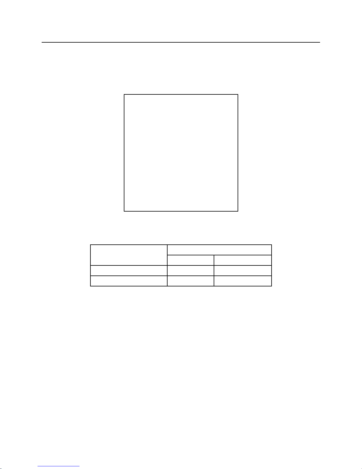
TEMPERATURE RANGE
⁰F
⁰C
HYDRAULIC FLUID
14 to 176
(-10 to +80)
ATMOSPHERIC
14 to 122
(-10 to +50)
GENERAL MAINTENANCE
HOSE INSTALLATION TIPS
5. Make sure the hose being installed is routed with the proper bend radius to prevent
kinking, flow restrictions, or hose failures at the hose connection.
6. Hoses should be used within the following ranges of temperature.
52
Page 54

GENERAL MAINTENANCE
CUTTER BLADE MAINTENANCE
When cutter blades become damaged or rounded due to abrasion, grind the rounded
areas of the blades (BG) to a sharp 90° edge.
Use care in handling to avoid bodily harm.
Do not over grind the blades to the point that the surface becomes blue or discolored.
This will make the blades brittle.
Cutter blades can be flipped four times to increase service life. Replace the cutter blade
if it is cracked, chipped, or worn beyond repair.
53
Page 55

GENERAL MAINTENANCE
CUTTER BLADE MAINTENANCE
DO NOT WELD CUTTER BLADES!
Torque the cutter blade bolts (OO) to specification; see the “FASTENER TORQUE”
section of this manual.
BLADE-TO-BLADE CLEARANCE
Fig. 1
A blade-to-blade (A-A) clearance of .010” to .040” (0.25 to 1.00 mm) should be
maintained for optimum performance. Install shims (BH) under blade (BG) as
necessary, see Fig. 1.
54
Page 56

MODEL
NPK SHIM
KIT PART
NUMBER
U21J, U21JR
U2100-1063
U31J, U31JR
S1850-7000
U45J,U45JR
1615250
G7
1609371
G18J
S1850-7000
G26J
S1850-7000
G30JR
S1850-7000
GENERAL MAINTENANCE
SHIM KITS
55
Page 57

U SERIES
G SERIES
JAW INSPECTION AND MAINTENANCE
WEEKLY INSPECTION
Inspect the jaw teeth for wear. Hard face worn areas as needed. The jaw teeth can be
cut off and replaced when worn beyond rebuild limits. On some models, a replaceable
tooth plate is available. Working with excessively worn jaws will reduce working
efficiency.
MINIMUM DISTANCE BETWEEN FIXED AND MOVEABLE
JAW
The distance between the fixed and moveable jaw must be maintained on U and G
Series Crushers so that the crusher cylinder will not reach full stroke and become
bottomed during operation.
56
Page 58
TABLE 1
d3a - DIMENSION
CRUSHER
Minimum Gap
MODEL
in.
(mm)
U21J
4-15/16"
(124)
U21JR
4-15/16"
(124)
U31J
3-15/16"
(100)
U31JR
3-15/16"
(100)
U45J
5-15/16"
(135)
U45JR
5-15/16"
(135)
G7
2-9/16"
(65)
G18J
2-3/4"
(70)
G26J
3-15/16"
(100)
G30JR
3-15/16"
(100)
TABLE 2
d3b - DIMENSION
CRUSHER
Approx. Std. Gap
MODEL
in.
(mm)
U21J
5-1/2"
(140)
U21JR
5-1/2"
(140)
U31J
5"
(127)
U31JR
5"
(127)
U45J
5-3/4"
(145)
U45JR
5-3/4"
(145)
G7
3"
(77)
G18J
3-15/16"
(100)
G26J
5"
(127)
G30JR
5"
(127)
JAW INSPECTION AND MAINTENANCE
WEEKLY INSPECTION
If the cylinder reaches full stroke and becomes
bottomed out, damage to the cylinder head cap (c5)
and retaining cap screws (OO) can occur.
When the jaw teeth on moveable (BD) and fixed (BI)
jaws become worn, allowing the gap to become less
than the minimum (d3a) shown in TABLE 1, the teeth
must be replaced or builtup by welding to reach the
standard dimension (d3b) shown in TABLE 2.
See TEETH BUILDUP OR TEETH REPLACEMENT
57
Page 59

JAW INSPECTION AND MAINTENANCE
TEETH MAINTENANCE and REPLACEMENT
The U and G Series Crushers have three types of jaw teeth. The large tooth (mp1) and
small teeth (mp2) are found on the moveable jaw and the flat teeth (mp8) are found on
the main frame. Both types can be built up by hard facing or cut off and replaced when
worn beyond NPK specification.
MOVEABLE JAW BUILDUP and HARDFACING
For buildup and hard facing, use NPK templates (t72) to check teeth so that they are to
the original profile. Contact NPK for the correct templates for each model. Then, refer
to JAW and TOOTH REBUILD PROCEDURE.
CY – NEW PROFILE, CZ – WORN PROFILE
58
Page 60

JAW INSPECTION AND MAINTENANCE
MOVEABLE JAWS: Wear on the small outside side teeth (mp5) determines when the
cylinders are approaching full extension. The large center teeth (mp6) are for crushing
purposes only.
TEETH REPLACEMENT
Following is the procedure for teeth replacement:
1. Remove worn teeth by carbon arc (t12) or acetylene cutting torch (t13).
2. Prepare surface for new teeth.
3. Place new teeth into proper location.
4. Heat dry welding rod to 300°F+ (150°C+).
5. Pre-heat weld area to 300°F - 400°F (150°C - 200°C).
6. For joining, stringer beads are best. For buildup, weaving is acceptable. Use one of
the following rods (or wire equivalent) or equal: Airco Austex 361, Cronatron 7770,
Eutectic 3205, Hobart Smooth Arc MC, McKay Chrome-mang, Stoody 2110.
7. Hardface rod for tooth and structure wear surfaces. Pre-heat as in Step number 5.
Use two passes maximum for hard facing. Use one of the following rods (or wire
equivalent) or equal: Airco Hardcraft CR-70, Cronatron 7350, Eutectic Eutectrode
N70, Hobart Smooth Arc 16 McKay Hardalloy 40 Tic, Stoody 19, 21, or 77.
8. Adjust weld current to rod manufacturer’s specification.
9. Peen each layer.
10. Cool slowly. Cover weld in cold environments.
59
Page 61

JAW INSPECTION AND MAINTENANCE
REPLACEABLE TOOTH PLATES – MOVEABLE JAWS
Another alternative is to replace the entire bolt on plates (BE).
The male jaw (BD) tooth plate (BE) is replaceable on all U21J, U21JR, U31J, U31JR,
U45J, U45JR, G18J, G26J, and G30JR models. Contact NPK for part numbers.
REPLACEABLE TOOTH PLATES – MAIN FRAME
The main frame (BI) tooth plate (BE1) is replaceable on all U21JA and U31JA models.
Contact NPK for part numbers.
60
Page 62

JAW INSPECTION AND MAINTENANCE
JAW AND TOOTH REBUILD PROCEDURE: ALL MODELS
Due to the abrasive nature of the material being crushed, jaw wear will occur on the U
and G Series Crushers. The jaws must be built up with hard face weld when the
clearance between the tip of the jaws in the closed position is worn to the extent that the
material can no longer be crushed efficiently.
To ensure maximum crushing performance, this rebuild procedure comprised of three
steps, should be followed:
1. Surface Preparation.
2. Underlayment Weld.
3. Hard Face Weld.
1. SURFACE PREPARATION
Grind the entire worn area until it is smooth and clean. Remove all paint, grease, oil,
dirt and old hard facing material before welding.
2. UNDERLAYMENT
Underlayment weld is necessary to build up the base material (DH) to match the original
jaw or tooth profile before hard facing. You cannot hard face over old hard facing.
Welding rod: Airco Austex 361, Cronatron 7770, Eutectic 3205, Postalloy 205,
Stoody 2110 or equal. In Canada: NCH Canada Inc. Hi-Pact #194 or equal.
Dry welding rod at 300°F+ (150°C+).
Pre-heat the jaw area to 300° - 400°F (150° - 200°C) and maintain this
temperature during the welding operation. It is very important to maintain this
temperature in cold environments.
Adjust weld current to rod manufacturer’s specifications.
Peen each layer.
Cool slowly. Cover weld in cold environments.
61
Page 63

JAW INSPECTION AND MAINTENANCE
JAW AND TOOTH REBUILD PROCEDURE: ALL MODELS
3. HARD FACE
Hard face (we3) can only be applied over base material (DH) or underlayment weld
(we2). NEVER HARD FACE OVER EXISTING HARD FACE!
Welding Rod: Airco Tubecraft 1A, Cronatron 7355, Eutectic N6006, Postalloy 214,
Stoody 31 or equal. In Canada: NCH Canada Inc. Wear-X #176 or equal.
Dry welding rod at 300°F+ (150°C+).
Pre-heat the jaw weld area to 350°F (177°C) and maintain this temperature during
welding operation. It is very important to maintain this temperature in cold
environments.
Adjust weld current to rod manufacturer’s specifications.
Peen each layer. Do not exceed 2 – 3 layers of hard face.
Cool slowly. Cover weld in cold environments.
62
Page 64

1. BEFORE WELD
2. AFTER WELD
CORRECT
BD/BI
MALE OR FEMALE
CRUSHER JAW
DI
WORN AREA
we2
UNDERLAYMENT
we3
HARDFACE
CORRECT
BD/BI
MALE OR FEMALE
CRUSHER JAW
we2
UNDERLAYMENT
we3
HARDFACE
we5
END OF NEW WELD
we6
OLD WELD
73
FINISH GRIND TO
BLEND
INCORRECT
BD/BI
MALE OR FEMALE
CRUSHER JAW
we4
OVERFLOW
we5
END OF NEW
WELD
JAW INSPECTION AND MAINTENANCE
JAW AND TOOTH REBUILD PROCEDURE: ALL MODELS
DO NOT WELD OVER OLD HARD FACING!
Remove all old hard facing before applying new underlay weld.
JAW CONTACT AREAS
MAIN FRAME and MOVEABLE JAW
CONTACT AREAS
In contact areas of jaws, hard facing (we3) may be
added to increase the wear life of these surfaces
for hard facing instructions, see the JAW and
TOOTH REBUILD PROCEDURE.
63
Page 65

MAIN FRAME REWORK GUIDE
Consult with the NPK Service Department to determine which rework procedure is
required.
U21J-5206 (U21J), U31J-5200 (U31J), and U45J-5202 (U45J) are the procedures to be
followed for normal main frame rework.
NORMAL WEAR
U21J-5207 (U21J), U31J-5201 (U31J), and U45J-5201 (U45J) are the procedures to be
followed for excessive main frame rework.
U21J-5208 (U21J), U3150-9000 (U31J), and U45J-5200A (U45J) are the procedures to
be followed for extreme main frame rework.
EXCESSIVE WEAR
EXTREME WEAR
64
Page 66

1. Gouge any cracks 100% using an air
or electric hand held grinder (t1),
carbon arc (t12) or torch (t13).
FRAME MAINTENANCE – REPAIR OF MAIN
FRAME
Inspect frame for cracks periodically. Crushing is an abusive operation and eventually
frame cracking may occur. If the attachment has been overstressed due to improper
operation or has been used for many hours of operation, the steel components may
develop fatigue cracks. If cracking is found in any of the steel components of the
processor, photos of the crack or cracks must be emailed to NPK immediately so that
the crack can be evaluated and a repair option recommended.
Use a crosshatch (BY) pattern on wear areas of the crusher as shown. Refer to the
TEETH REPLACEMENT section for hard face rods and procedure.
ROUTE WELD REPAIR
65
Page 67
2a. Grind gouged area to a 30° angle on
each side to the full depth of the
gouged area for plate sizes up to 3/4"
(19 mm) thick.
2b. Grind gouged area to a 45° angle on
each side to the full depth of the
gouged area for plate sizes over 3/4"
(19 mm) thick.
3. If the crack is completely through the plate, grind the bevel in halfway from both
sides. Remove all slag and grinding residue.
4. Consult the JAW and TOOTH REBUILD PROCEDURE, HARD FACE section for
pre-heat and welding instructions.
5. Peen or stress relieve after each pass. Maintain pre-heat.
6. After welding, grind area flush.
22
DIRECTION OF GRINDING
23
DIRECTION OF PRINCIPLE STRESS
7. Allow area to cool slowly (eight hours minimum). Cover with a heat blanket or other
suitable insulation. FAILURE TO DO SO MAY CAUSE CRYSTALLIZATION OF
THE WELD AND SUBSEQUENT BREAKAGE.
FRAME MAINTENANCE – REPAIR OF MAIN
FRAME
ROUTE WELD REPAIR
NOTE: NPK Construction Equipment has developed this repair procedure based on
known information about structure and material. This, however, does not imply that
repairs made using this procedure are guaranteed to be successful. NPK, therefore,
cannot warranty this procedure. There is NO warranty regarding this repair either
expressed or implied.
66
Page 68

1. Remove the Booster Assembly (bs35)
from the cylinder (c11).
NOTE: See the Booster Manual
(B000-9600) for Booster maintenance.
2. Remove the spacers (bs23), o-rings
(RR), and backup rings (SS) from the
cylinder assembly (c11).
3. Remove the cylinder end cap socket
head cap screws (OO).
4. Remove the cylinder rod assembly
(c48) from the cylinder housing (c4).
INSPECTION AND MAINTENANCE
BOOSTER CYLINDER
DISASSEMBLY
67
Page 69

5. Check the piston rings (c8). The rings
should be free in their grooves. If the
rings are found to be stuck in their
grooves, use a die grinder with a soft
polishing stone (preferably NPK polishing
wheel p/n 25026030) and polish the rings
until they spring out of their grooves. If a
ring is broken, it must be replaced.
6. Using a ring expander (t16), remove all of
the piston rings.
7. If used, lightly heat the rod nut set screw
(c6) to loosen any thread adhesive that is
present. Remove the rod nut set screw.
8. Unscrew the rod nut (c1) and remove the piston (c2) from the cylinder rod (c3).
Remove the cylinder end cap (c5).
INSPECTION AND MAINTENANCE
BOOSTER CYLINDER
DISASSEMBLY
68
Page 70

9. Remove the dirt seal (QQ), rod seal (PP),
o-ring (RR), and backup rings (SS) from
the cylinder end cap (c5) and discard.
10. Remove the o-ring (RR) and backup
rings (SS) from the inside of the piston
(c2) and discard.
INSPECTION AND MAINTENANCE
BOOSTER CYLINDER
DISASSEMBLY
69
Page 71

INSPECTION AND MAINTENANCE
CYLINDER COMPONENTS
INSPECTING AND CLEANING
The prevention of foreign contaminant damage is critical when working with hydraulic
equipment. Keep the work area clean. Using masking tape, cover all exposed holes
and parts which may allow entry of foreign contaminants. Habitually clean the work
area by wiping with a lint-free cloth.
Mating surfaces are machined to a smooth surface. Use care to avoid scratches, nicks,
dents, or other damage to machined surfaces. If damaged, the component must be
repaired or replaced as required.
1. Inspect the heads and threads of all fasteners and plugs and corresponding
threaded bores for damage. Repair or replace as required.
2. Inspect all components, particularly machined surfaces, including all hydraulic
ports, for evidence of scratches, scoring, nicks, dents, wear, deformity or other
damage. Particularly close attention should be given to o-ring grooves and
counter bores. Repair or replace as required.
3. Inspect drained and residual hydraulic fluid for evidence of contamination. If
contaminated, inspect all components, seal, etc., to determine the cause.
4. Inspect the cylinder housing (c4) bore. Lightly hone using a ball hone (t17). If
there is heavy scoring, the cylinder housing will need to be replaced.
5. Inspect the bronze guide (c10) found in the cylinder end cap (c5) for damage or
excessive wear.
70
Page 72

INSPECTION AND MAINTENANCE
CYLINDER COMPONENTS
INSPECTING AND CLEANING
6. Using a die grinder with a soft polishing stone (t8), preferably NPK polishing wheel
p/n 25026030, polish the leading edges of the piston ring grooves (25) to remove
damage to the piston and allow free movement of the piston rings.
7. Using a straight edge (t15), check the cylinder rod (c3) for straightness.
NOTE: The cylinder rod is a forged, high strength part. It is not possible to repair
the rod. If the rod is bent or damaged, it must be replaced.
8. Clean all parts with a degreaser solvent using a Scotchbrite® or equivalent cleaning
pad.
Compressed air can cause injury or death! Limit air pressure to a maximum of
30 psi (2 bars). Protect your eyes with safety glasses! Do not direct compressed air
current at exposed skin! Do not direct compressed air current at other people within
the work area!
71
Page 73

Air or electric handheld grinder (NPK model NHG-65LD recommended)
Polishing wheel for grinder (NPK p/n 25026030)
NPK Assembly Lube (p/n H010-5010)
Emery cloth (200 grit)
Cleaning solvent
INSPECTION AND MAINTENANCE
CYLINDER COMPONENTS
INSPECTING AND CLEANING
9. Remove all thread sealant from threads using an appropriate thread sealant solvent.
Remove old thread sealant residue with a maximum of 30 psi (2 bars) of
compressed air.
REPAIR TOOLS AND EQUIPMENT
72
Page 74

1. Install dirt seal (QQ), backup ring (SS),
and piston seal (PP) into the seal
grooves on the inner side of the
cylinder end cap (c5). Install the oring and backup ring into the outer
groove.
2. Apply hydraulic oil or NPK Assembly Lube (p/n H010-5010) to the inner surface
coating the previously installed dirt seal, backup ring, and piston seal. Install the
cylinder end cap (c5) onto the cylinder rod.
3. Install the o-ring (RR) and backup
rings (SS) into the piston (c2). Apply a
light coat of hydraulic oil or NPK
Assembly Lube to the o-ring and
backup rings after installation.
INSPECTION AND MAINTENANCE
CYLINDER COMPONENTS
ASSEMBLY
73
Page 75

4. Install the piston (c2), with the dimple
(24) facing away from the rod eye,
onto the cylinder rod.
5. Apply high strength thread adhesive
(t41) to the clean dry threads (th1) of
the cylinder rod (c3).
NOTE: New style cylinder rod nuts
(without set screws) have a nylon
patch and do not require thread
adhesive.
6. There are three styles of piston lock nuts (c1). Lock nut set screw (c6) location
changes. Style “A” shows the early factory style. Style “B” shows the current
factory style. Style “C” shows the replacement style. Style “C” uses a nylon patch
(c52) instead of a set screw.
Style “A”
Style “B”
Style “C”
INSPECTION AND MAINTENANCE
CYLINDER COMPONENTS
ASSEMBLY
74
Page 76
7. Thread cylinder rod nut (c1) onto the cylinder rod (c3) and torque to the listed
value below.
MODEL
THREAD
TORQUE
SOCKET
ROD NUT PART NUMBER
SIZE
ft. lb.
(Nm)
SIZE
STYLE
"A"
STYLE
"B"
STYLE
"C"
U21J
M65 x 3.0
3,250
(4,400)
90 mm
16032575
16084717
X
U21JR
M65 x 3.0
3,250
(4,400)
90 mm
16032575
16084717
X
U31J
M70 x 3.0
4,100
(5,500)
120 mm
16039992
16084683
G180-1000
U31JR
M70 x 3.0
4,100
(5,500)
120 mm
16039992
16084683
G180-1000
U45J
M70 x 3.0
4,100
(5,500)
140 mm
X
16064537
X
U45JR
M70 x 3.0
4,100
(5,500)
140 mm
X
16064537
X
G7
M45 x 1.5
1,500
(2,000)
70 mm
16043050
X
X
G18J
M65 x 3.0
3,250
(4,400)
100 mm
16053903
X
S2250-4500
G26J
M70 x 3.0
4,100
(5,500)
120 mm
16039992
X
G180-1000
G30JR
M70 x 3.0
4,100
(5,500)
120 mm
16039992
X
G180-1000
8. Install the set screw. If the original factory lock nuts are to be re-used, a dimple
must be drilled into the piston rod (Style “A” type) or the piston (Style “B” type)
using the existing threaded hole as a guide. The maximum depth of the hole
should not exceed 1/64th inch (0.5 mm). Apply a small amount of medium strength
thread adhesive to the set screw before installing. If the lock nut is replaced (Style
“C” type), the replacement will have a nylon patch and will not require a set screw.
9. Using a ring expander (t16), install the
piston rings with the splits in the piston
rings opposing each other.
INSPECTION AND MAINTENANCE
CYLINDER COMPONENTS
ASSEMBLY
75
Page 77
10. Apply hydraulic oil or NPK Assembly
Lube to the inner surface of the
cylinder housing and to the outside
diameter of the piston and piston
rings.
11. Install the cylinder rod assembly
(c48) slowly into the cylinder housing
(c4) taking care not to damage the
piston rings (c8).
12. Install the cylinder end cap socket head cap screws (OO) and torque to the value
listed below.
MODEL
BOLT
TORQUE
SIZE
ft. lb.
(Nm)
U21J
M18-2.5
260
(350)
U21JR
M18-2.5
260
(350)
U31J
M20-2.5
365
(500)
U31JR
M20-2.5
365
(500)
U45J
M20-2.5
365
(500)
U45JR
M20-2.5
365
(500)
G7
M16-2
190
(255)
G18J
M18-2.5
260
(350)
G26J
M20-2.5
365
(500)
G30JR
M20-2.5
365
(500)
INSPECTION AND MAINTENANCE
CYLINDER COMPONENTS
ASSEMBLY
76
Page 78

13. Apply a light coat of oil or NPK
Assembly Lube to four new backup
rings (SS), four new o-rings (RR)
and the two spacers (bs23), then
install in the corresponding counter
bores of the main cylinder assembly
(c11).
14. Apply a light coat of oil or NPK
Assembly Lube to the mating
surfaces of the booster main body.
15. With the aid of an assistant, carefully
orient and align the eight mounting
flange fastening holes of the booster
assembly (bs35) with the
corresponding eight threaded bores
of the cylinder assembly (c11). If
necessary, install two eye-bolts in
the threaded bores on top of the
booster assembly. Lift and move the
booster assembly using a hoist.
INSPECTION AND MAINTENANCE
CYLINDER COMPONENTS
ASSEMBLY
77
Page 79

16. Apply high-strength thread sealant to
the clean, dry threads of the eight
previously removed cap screws.
17. Secure the main booster assembly
to the cylinder housing using the
eight cap screws and washers.
Tighten the cap screws in an
opposing pattern. Torque to value
listed to the right.
MODEL
BOLT
TORQUE
SIZE
ft. lb.
(Nm)
U21J
M16-2
225
(300)
U21JR
M16-2
225
(300)
U31J
M16-2
225
(300)
U31JR
M16-2
225
(300)
U45J
M18-2.5
260
(350)
U45JR
M18-2.5
260
(350)
G7
M14-2
145
(200)
G18J
M16-2
225
(300)
G26J
M16-2
225
(300)
G30JR
M16-2
225
(300)
INSPECTION AND MAINTENANCE
CYLINDER COMPONENTS
ASSEMBLY
78
Page 80
CRUSHER
PART
FUNCTION
NOTES
MODEL
NUMBER
U21
U2100-9510
FIXED TO ROTATION TYPE
U21
U2100-9500
ROTATION TO FIXED TYPE
crusher code number
322701 and earlier
U21
U2100-9501
ROTATION TO FIXED TYPE
crusher code number
322704 and newer
U31
U3100-9510
FIXED TO ROTATION TYPE
U31
U3100-9500
ROTATION TO FIXED TYPE
crusher code number
322501 and earlier
U31
U3100-9501
ROTATION TO FIXED TYPE
crusher code number
322502 and newer
U45
U4500-9500
ROTATION TO FIXED TYPE
m27
Swivel Top
m45
Fixed Top
TOP BRACKET CONVERSION
CONVERSION PACKAGES OFFERED FOR “U” SERIES
CRUSHERS
A. Safe handling procedures must be followed to avoid personal injury.
B. Lifting and securing mechanisms must be of adequate capacity to safely support
the particular crusher.
79
Page 81

MODEL
NEW MAXIMUM
in
(mm)
U21JR
(U21JRA)
<.010
(<0.25)
U31JR
(U31JRA)
<.010
(<0.25)
U45JR
<.010
(<0.25)
G30JR
<.010
(<0.25)
MODEL
MAXIMUM
ALLOWABLE
WEAR
in
(mm)
U21JR
(U21JRA)
0.138
(3.50)
U31JR
(U31JRA)
0.138
(3.50)
U45JR
0.138
(3.50)
G30JR
0.138
(3.50)
SLEWING RING INSPECTION AND
MAINTENANCE
MEASURING MAXIMUM AXIAL MOVEMENT
1. While the unit is attached to the carrier, position the crusher in a vertical position as
shown.
2. Lock the base of a dial indicator (t40) onto the lower frame of the crusher. Indicate
the other end of the dial onto the top bracket face as shown. Using the excavator,
slightly rock the crusher back and forth using slight stick movement. Note the
movement shown on the dial. Take this reading (d59) in four places. If your
readings are greater than shown, please contact the NPK Service Department at 1800-225-4379.
80
Page 82
MODEL
SLEWING RING
DIRT SEAL
PART NUMBER
PART NUMBER
U21JR
25309660
25309273
U31JR
25309680
25309353
U45JR
25309840
25309843
Additional items needed:
High strength adhesive
Brake clean/solvent
1. Remove old seal (QQ) from the bottom side
(72) of the slewing ring (BT).
2. Thoroughly clean oil, grease and dirt from the
seal groove (118) and surrounding areas.
3. Clean seal groove with brake clean/solvent
and allow time to dry completely.
4. Apply a small amount of high strength
adhesive into the groove and install one end
of the seal. Take care not to get adhesive
on the lower lip of the seal.
5. Insert seal into the groove and work around
the slewing ring applying a small amount of
adhesive every 12 in. (300 mm). Take care
not to stretch the seal as it is being
installed around the slewing ring.
6. Cut excess seal material as you get back
around to the other end so the seal will butt
against itself tightly. Apply adhesive to the
groove and end of the seal to make it one
continuous ring.
SLEWING RING INSPECTION AND
MAINTENANCE
ROTATION BEARING OUTER DIRT SEAL REPLACEMENT
81
Page 83

Fig. 1
Fig. 2
CRUSHER RELIEF LOCATIONS
U21J, U21JR, U31J, U31JR, U45J, U45JR, G30JR
Relief valve cartridges (c17/c18) for the “U” Series and the G30JR are located on the
swivel manifold on rotating units (see Fig. 1) and below the joint assembly on fixed units
(see Fig. 2). The relief cartridges are accessed through the same inspection plates on
all models shown above.
G7, G18J, G26J
Relief valve cartridges (c17) for the G7, G18J AND G26J Crushers are mounted on the
cylinder boosters (see Fig. 3).
Fig. 3
82
Page 84

MODEL
MINIMUM CARRIER
CRUSHER
RELIEF
REQUIRED
RELIEF SETTING
SETTING
OIL FLOW
psi
(bar)
psi
(bar)
gpm
(l/m)
U21J/U21JR
3,971
(274)
3,771
(260)
26 - 53
(98 - 200)
U31J/U31JR
4,261
(294)
4,061
(280)
26 - 66
(98 - 250)
U45J/U45JR
4,550
(314)
4,350
(300)
46 - 73
(175 - 275)
G7
3,200
(220)
3,000
(206)
13 - 21
(49 - 80)
G18J
3,900
(269)
3,700
(255)
26 - 52
(98 - 197)
G26J/G30JR
4,200
(290)
4,000
(275)
26 - 66
(98 - 250)
CRUSHER RELIEF LOCATIONS
G7, G18J, G26J
Before attempting to adjust the relief pressures of an NPK crusher, the carrier circuit
relief setting must be checked. The circuit relief setting must be at least 200 psi (14 bar)
above the crusher relief (operating) pressure. The test ports on the NPK shut-off valves
provided with NPK hydraulic kits are used for checking the carrier relief settings and to
test and set the crusher relief cartridges. If not using an NPK hydraulic kit, a similar
provision must be made to check pressures. Refer to the “HYDRAULIC
INSTALLATION” section of this manual or call the NPK Service Department at 1-800225-4379.
83
Page 85

SWIVEL MANIFOLD MAINTENANCE
SWIVEL MANIFOLD ASSEMBLY
The swivel manifold assembly is located between the top bracket, which is pinned to the
carrier, and the crusher frame that rotates. Hydraulic oil for both the open and close
operations of the crusher pass through this manifold. The swivel manifold assembly
consists of two main parts, the “Spindle Case” (BZ), which contains the oil seals, and
the “Spindle” (CA), which rotates with the crusher frame (see Fig. 1).
LEAKAGE OF THE SEALS
External leakage or internal bypassing of hydraulic fluid will require the replacement of
the seals in the swivel assembly. For external leakage, please review the seal
replacement procedure in the “REPLACEMENT OF THE SEALS IN THE SWIVEL”
section of this manual. If internal leakage is suspected, please proceed to the
“TESTING THE SWIVEL SEALS FOR INTERNAL LEAKAGE” in the next section.
TESTING THE SWIVEL SEALS FOR INTERNAL LEAKAGE
If internal leakage is suspected, before disassembling the swivel assembly, the relief
valve pressure settings should be checked. Internal leakage will most likely prevent the
unit from reaching its relief settings in both the open and close functions. The relief
valve cartridges are located in blocks (bs24) mounted to the swivel manifold assembly
near the two hose connections (see Fig. 2). Access to these is through the upper side
access plates of the crusher main frame (see “CRUSHER RELIEF LOCATIONS”).
The relief valve setting adjustment screws (va1) are located beneath plastic caps (FN).
NOTE: Before attempting to adjust the relief setting, check that the relief valve
cartridges have not loosened in their blocks.
Fig. 1
Fig. 2
84
Page 86

SWIVEL MANIFOLD MAINTENANCE
TESTING THE SWIVEL SEALS FOR INTERNAL LEAKAGE
TEST PROCEDURE
Install 0 to 5,000 psi (0 to 350 bar) gauges in the NPK stop valves (located on the stick
of the carrier) or in gauge ports in the open and close circuits located near the end of
the stick (for carriers without an NPK hydraulic kit). Close the jaw and keep the function
activated, then read the pressure indicated on the gauge. Compare the pressure
reached with the specifications for your model crusher. Repeat the check while opening
the jaws and read the pressure indicated. If the proper relief pressure cannot be
reached and the booster slows or stops, disassemble the swivel to check for failed
seals. NOTE: If the relief pressure cannot be reached with the jaw closed and the
intensifier booster is clicking rapidly, the relief valves are not the problem and the
intensifier booster should be checked.
REPLACEMENT OF THE SEALS IN THE SWIVEL
Tools needed:
19 and 22 mm open end wrenches
41 and 46 mm open end wrenches
External snap ring pliers
The jaws of the crusher should be closed and the frame supported or the shipping pins
(t80), as shown in Fig. 3, installed to prevent rotation during repair.
Fig. 3
85
Page 87

STEP 1 (Fig. 4)
Disconnect the rotation hoses (m39) at
the counterbalance valve (BO). Remove
the rotation motor hoses and motor
fittings (f1) from the hydraulic motor.
Disconnect the cylinder hoses (AO) at the
side plates of the top bracket. Do not
remove the cylinder hoses and fittings
from the “Spindle Case” (BZ), they will
be used to help lift it off the “Spindle”
(CA). Do not disturb the elbow fittings
(f4) in the “Spindle Case”.
Fig. 4
STEP 2 (Fig. 5)
Remove the snap ring (AJ) and washer
(U) from the top of the swivel assembly.
Pull the “Spindle Case” off of the
“Spindle” (the cylinder hoses can be
used for this).
Fig. 5
STEP 3 (Fig. 6)
Inspection:
Visually inspect the sealing surfaces
(120) of the “Spindle” (CA) for damage,
which may hamper the ability of the orings to seal. Polishing the surface may
clean up light scratching. Heavy
scratching or galling may indicate rotator
bearing play.
Fig. 6
SWIVEL MANIFOLD MAINTENANCE
REPLACEMENT OF THE SEALS IN THE SWIVEL
86
Page 88

STEP 4 (Fig. 7)
Seal removal and replacement:
Sealing is accomplished with a
combination of o-rings and back-up rings,
which ride against the “Spindle”.
Remove the o-rings and back-up rings
with a seal pick (note the order of
placement). Check the grooves (118) in
the “Spindle Case” (BZ) for burrs or
scoring damage. Light grinding or
polishing may be required.
Fig. 7
STEP 5 (Fig. 8)
Lubricate the o-rings (RR) and back-up
rings (SS) with grease. Install the backup rings first, taking care not to crimp or
fold them. Install the o-ring. Refer to the
illustration for o-ring and back-up ring
placement.
Fig. 8
Spray the “Spindle” (CA) with NPK
assembly lube (P/N H010-5010). Install
the hoses onto the “Spindle Case” (BZ).
Slide the “Spindle Case” over the
“Spindle”, which includes the relief valve
cartridges (c17/c18). Install the washer
(U) and snap ring (AJ). Reconnect the
cylinder hoses to the top bracket, install
the fittings into the hydraulic motor and
install the hydraulic motor hoses.
SWIVEL MANIFOLD MAINTENANCE
REPLACEMENT OF THE SEALS IN THE SWIVEL
87
Page 89

FASTENER TORQUE SPECIFICATIONS
These torque charts are to be used with the specific “U” or “G” Series Crusher parts
manual for the unit being paired.
All fasteners will be used with lube or medium strength thread adhesive. Bolts must
have their threads wire brushed or cleaned with a thread die, then cleaned with solvent
and finally cleaned with compressed air. Threaded holes must be cleaned with a thread
tap, solvent and also with compressed air.
Use a common chassis or wheel bearing grease on fasteners listed as lubed. Grease
the threads of the bolt and the contact surface under the bolt head. Grease the contact
surface of nuts.
Use a few drops of medium strength thread adhesive on the threads of fasteners listed
as torqued with adhesive.
Do not use anti-seize compound on any fasteners, unless otherwise noted.
88
Page 90
FASTENER TORQUE CHART - MAIN FRAME ASSEMBLY
BOLT LOCATION
MODEL
BOLT
SIZE
BOLT TORQUE
ADHESIVE
ft. lb.
(Nm)
OR LUBED
CYLINDER ROD END
U21J/JR
M16
260
(350)
LUBED
PIVOT PIN KEEPER
U31J/JR
M16
260
(350)
LUBED
U45J/JR
M18
330
(450)
LUBED
CYLINDER PIVOT
U21J/JR
M18
330
(450)
LUBED
FLANGE
U31J/JR
M20
480
(650)
LUBED
U45J/JR
M20
480
(650)
LUBED
JAW PIVOT PIN NUT
U21J/JR
M16
260
(350)
LUBED
U31J/JR
M16
260
(350)
LUBED
U45J/JR
M16
260
(350)
LUBED
CUTTING BLADE
U21J/JR
M14
150
(200)
LUBED
U31J/JR
M16
260
(350)
LUBED
U45J/JR
M16
260
(350)
LUBED
TOOTH PLATE
U21J/JR
M20
480
(650)
ADHESIVE
MOVEABLE JAW
U31J/JR
M24
775
(1050)
ADHESIVE
U45J/JR
M24
775
(1050)
ADHESIVE
TOOTH PLATE
U21JA
M24
775
(1051)
ADHESIVE
FIXED JAW
U31JA
M30
1350
(1830)
ADHESIVE
COVER PLATE
U21J/JR
M16
260
(350)
LUBED
U31J/JR
M16
260
(350)
LUBED
U45J/JR
M16
260
(350)
LUBED
JOINT FITTING
U21J/JR
M12
65
(90)
LUBED
U31J/JR
M12
65
(90)
LUBED
U45J/JR
M12
65
(90)
LUBED
JOINT ASSEMBLY
U21J
M16
205
(280)
ADHESIVE
U31J
M16
260
(350)
ADHESIVE
U45J
M16
260
(350)
ADHESIVE
SPINDLE BLOCK
U21J
M10
45
(60)
LUBED
U31J
M10
45
(60)
LUBED
U45J
M10
45
(60)
LUBED
FLANGE ADAPTER
U31J
M12
80
(105)
LUBED
FASTENER TORQUE SPECIFICATIONS
89
Page 91
FASTENER TORQUE CHART - MAIN FRAME ASSEMBLY
BOLT LOCATION
MODEL
BOLT SIZE
BOLT TORQUE
ADHESIVE
ft. lb.
(Nm)
OR LUBED
CYLINDER ROD END
G7
M16
190
(255)
LUBED
PIVOT PIN KEEPER
G18J
M16
260
(350)
LUBED
G26J
M16
260
(350)
LUBED
G30JR
M16
260
(350)
LUBED
CYLINDER PIVOT
G7
M14
120
(165)
LUBED
FLANGE
G18J
M18
260
(350)
LUBED
G26J
M20
480
(650)
LUBED
G30JR
M20
480
(650)
LUBED
JAW PIVOT PIN NUT
G7
M12
80
(105)
LUBED
G18J
M16
260
(350)
LUBED
G26J
M16
260
(350)
LUBED
G30JR
M16
260
(350)
LUBED
CUTTING BLADE
G7
M14
120
(165)
LUBED
G18J
M16
260
(350)
LUBED
G26J
M16
260
(350)
LUBED
G30JR
M16
260
(350)
LUBED
TOOTH PLATE
G18J
M20
480
(650)
ADHESIVE
MOVEABLE JAW
G26J
M24
640
(950)
ADHESIVE
G30JR
M24
640
(950)
ADHESIVE
COVER PLATE
G18J
M16
260
(350)
LUBED
G26J
M16
260
(350)
LUBED
G30JR
M16
260
(350)
LUBED
JOINT FITTING
G7
M12
65
(90)
LUBED
G18J
M16
190
(255)
LUBED
G26J
M12
65
(90)
LUBED
G30JR
M12
65
(90)
LUBED
NOTE:
"G" crushers that have a "J" in the model
designation have tooth plates that bolt to the
moveable jaw.
FASTENER TORQUE SPECIFICATIONS
90
Page 92

FASTENER TORQUE CHART - CYLINDER ASSEMBLY
BOLT LOCATION
MODEL
BOLT SIZE
BOLT TORQUE
ADHESIVE
ft. lb.
(Nm)
OR LUBED
CYLINDER END CAP
U21J/JR
M18
260
(350)
LUBED
U31J/JR
M20
365
(500)
LUBED
U45J/JR
M20
365
(500)
LUBED
CYLINDER ROD NUT
U21J/JR
M45
1400
(1900)
ADHESIVE
U31J/JR
M65
3200
(4400)
ADHESIVE
U45J/JR
M65
3200
(4400)
ADHESIVE
CYLINDER GUARD
U21J/JR
M24
640
(870)
ADHESIVE
U31J/JR
M30
400
(550)
ADHESIVE
U45J/JR
M30
400
(550)
ADHESIVE
GUARD HOLDER
U21J/JR
M10
45
(60)
ADHESIVE
PLATE - TOP
U31J/JR
M10
45
(60)
ADHESIVE
U45J/JR
M12
80
(105)
ADHESIVE
GUARD HOLDER
U21J/JR
M16
205
(280)
ADHESIVE
PLATE - SIDE
U31J/JR
M16
260
(280)
ADHESIVE
U45J/JR
M20
405
(350)
ADHESIVE
BOOSTER
U21J/JR
M16
225
(300)
ADHESIVE
ASSEMBLY
U31J/JR
M16
225
(300)
ADHESIVE
U45J/JR
M18
260
(350)
ADHESIVE
BLOCK
U21J/JR
M12
93
(125)
ADHESIVE
U31J/JR
M12
93
(125)
ADHESIVE
U45J/JR
M12
93
(125)
ADHESIVE
CONNECTOR PIPE
U31J/JR
M12
93
(125)
ADHESIVE
U45J/JR
M12
93
(125)
ADHESIVE
NOTE:
For booster assembly bolt torques see B000-9600C booster
manual.
FASTENER TORQUE SPECIFICATIONS
91
Page 93
FASTENER TORQUE CHART - CYLINDER ASSEMBLY
BOLT LOCATION
MODEL
BOLT SIZE
BOLT TORQUE
ADHESIVE
ft. lb.
(Nm)
OR LUBED
CYLINDER END CAP
G7
M16
190
(255)
LUBED
(See NOTE₁)
G18J
M18
260
(350)
LUBED
G18J
M20
365
(500)
LUBED
G26J
M18
260
(350)
LUBED
G26J
M20
365
(500)
LUBED
G26J
M22
400
(550)
LUBED
G30JR
M20
365
(500)
LUBED
CYLINDER ROD NUT
G7
M45
1400
(1900)
ADHESIVE
G18J
M65
3200
(4400)
ADHESIVE
G26J
M70
4100
(5500)
ADHESIVE
G30JR
M70
4100
(5500)
ADHESIVE
CYLINDER GUARD
G7
M12
93
(125)
ADHESIVE
G18J
M30
400
(550)
ADHESIVE
G26J
M30
400
(550)
ADHESIVE
G30JR
M30
400
(550)
ADHESIVE
GUARD HOLDER
G18J
M10
45
(61)
ADHESIVE
PLATE - TOP
G26J
M10
45
(61)
ADHESIVE
G30JR
M10
45
(61)
ADHESIVE
GUARD HOLDER
G18J
M16
205
(280)
ADHESIVE
PLATE - SIDE
G26J
M16
190
(255)
ADHESIVE
G30JR
M16
260
(350)
ADHESIVE
SPACER PLATE
G7
M10
45
(61)
ADHESIVE
BRACKET - SIDE
G7
M12
93
(125)
ADHESIVE
BRACKET - BOTTOM
G7
M10
45
(61)
ADHESIVE
BOOSTER
G7
M14
145
(200)
ADHESIVE
ASSEMBLY
G18J
M16
225
(300)
ADHESIVE
(See NOTE₂)
G26J
M16
225
(300)
ADHESIVE
G30JR
M16
225
(300)
ADHESIVE
BLOCK
G18J
M12
93
(125)
ADHESIVE
G26J
M12
93
(125)
ADHESIVE
G30JR
M12
93
(125)
ADHESIVE
CONNECTOR PIPE
G18J
M12
93
(125)
ADHESIVE
G26J
M12
93
(125)
ADHESIVE
G30JR
M12
93
(125)
ADHESIVE
NOTE₁ :
Measure cylinder end cap bolt sizes on G18J and G26J units.
Several different bolt sizes have been used.
NOTE₂ :
For booster assembly bolt torques, see B000-9600C booster
manual.
FASTENER TORQUE SPECIFICATIONS
92
Page 94
FASTENER TORQUE CHART - ROTATION COMPONENTS
BOLT LOCATION
MODEL
BOLT
SIZE
BOLT TORQUE
ADHESIVE
ft. lb.
(Nm)
OR LUBED
SLEWING RING
U21JR
M24
700
(950)
LUBED
ASSEMBLY TO
U31JR
M24
775
(1050)
LUBED
FRAME
U45JR
M24
775
(1050)
LUBED
M27
1035
(1400)
LUBED
TOP PLATE TO
U21JR
M16
260
(350)
ADHESIVE
SLEWING RING
U31JR
M16
260
(350)
ADHESIVE
U45JR
M16
260
(350)
ADHESIVE
SLEWING RING
U21JR
M12
93
(125)
ADHESIVE
COVER
U31JR
M12
93
(125)
ADHESIVE
U45JR
M10
45
(60)
ADHESIVE
ROTATION MOTOR
U21JR
M16
260
(350)
ADHESIVE
U31JR
M16
260
(350)
ADHESIVE
U45JR
M16
260
(350)
ADHESIVE
MOTOR PINION
U21JR
M12
93
(125)
ADHESIVE
GEAR
U31JR
M12
93
(125)
ADHESIVE
U45JR
M12
93
(125)
ADHESIVE
COUNTERBALANCE
U21JR
M12
95
(130)
LUBED
VALVE
U31JR
M12
95
(130)
LUBED
U45JR
M12
95
(130)
LUBED
COUNTERBALANCE
U21JR
M12
95
(130)
LUBED
VALVE PLATE
U31JR
M12
95
(130)
LUBED
U45JR
M12
95
(130)
LUBED
ROTARY JOINT
U21JR
M16
205
(280)
ADHESIVE
ASSEMBLY
U31JR
M16
260
(350)
ADHESIVE
U45JR
M16
260
(350)
ADHESIVE
SPINDLE BLOCK
U21JR
M10
45
(60)
LUBED
U31JR
M10
45
(60)
LUBED
U45JR
M10
45
(60)
LUBED
FLANGE ADAPTOR
U31JR
M12
80
(105)
LUBED
LOCK PLATE
U21JR
M12
93
(125)
ADHESIVE
U31JR
M12
93
(125)
ADHESIVE
U45JR
M12
93
(125)
ADHESIVE
FASTENER TORQUE SPECIFICATIONS
93
Page 95

FASTENER TORQUE CHART - G30JR ROTATION COMPONENTS
BOLT LOCATION
BOLT
SIZE
BOLT TORQUE
ADHESIVE
ft. lb.
(Nm)
OR LUBED
SLEWING RING
M24
700
(950)
LUBED
ASSEMBLY TO
FRAME
SLEWING RING
M12
93
(125)
ADHESIVE
COVER
ROTATION MOTOR
M16
260
(350)
ADHESIVE
MOTOR PINION
M12
93
(125)
ADHESIVE
GEAR
COUNTERBALANCE
M12
95
(130)
LUBED
VALVE
COUNTERBALANCE
M12
95
(130)
LUBED
VALVE PLATE
ROTARY JOINT
M16
260
(350)
ADHESIVE
ASSEMBLY
SPINDLE BLOCK
M10
45
(60)
LUBED
FLANGE ADAPTOR
M12
80
(105)
LUBED
LOCK PLATE
M12
93
(125)
ADHESIVE
FASTENER TORQUE SPECIFICATIONS
94
Page 96

NOMINAL
SIZE
FITTING
DASH
SIZE
THREAD
SIZE
NUMBER OF
FLATS FROM
FINGER TIGHT
TORQUE
ft. lb.
(Nm)
1/2"
-8
3/4-16
1
36 - 39
(49 - 53)
3/4"
-12
1-1/16-12
1
79 - 88
(107 - 119)
1"
-16
1-5/16-12
1
108 - 113
(146 - 153)
1-1/4"
-20
1-5/8-12
1
127 - 133
(172 - 180)
NOMINAL
SIZE
FITTING
DASH
SIZE
THREAD
SIZE
NUMBER OF
FLATS FROM
FINGER TIGHT
TORQUE
ft. lb.
(Nm)
1/2"
-8
13/16-16
1.25 - 1.75
32 - 35
(43 - 48)
3/4"
-12
1-3/16-12
1.25 - 1.75
65 - 70
(88 - 95)
1"
-16
1-7/16-12
1.25 - 1.75
92 - 100
(125 - 136)
1-1/4"
-20
1-11/16-12
1.25 - 1.75
125 - 140
(170 - 190)
HOSE TORQUE SPECIFICATIONS
JIC ENDS
ORFS ENDS
95
Page 97

TROUBLESHOOTING
DETERMINE THE TYPE OF PROBLEM
Performance problems are classified as “LOSS OF POWER” or “LOSS OF CYCLE
SPEED” (assuming the problem is not due to misapplication).
1. LOSS OF POWER
NPK CRUSHER jaw crushing forces are determined by the operating pressure
setting and NPK pressure intensifier performance.
2. LOSS OF CYCLE SPEED
NPK CRUSHER cycle speed is determined by oil flow to the unit. The hydraulic
installation circuit for the CRUSHER must be set to provide the correct flow.
DETERMINE THE CAUSE OF THE PROBLEM
Technical problems are caused by either the NPK CRUSHER or the carrier’s hydraulic
system (hydraulic installation kit for the CRUSHER). Checking the hydraulic pressure
and flow will determine if the problem is in the CRUSHER or the carrier. If the pressure
and flow to the Crusher are correct, the problem is in the CRUSHER.
LOSS OF POWER
Loss of power can be caused by a low carrier relief valve setting or by a low CRUSHER
relief valve setting. Verify the correct relief valve settings of the carrier and the
CRUSHER. (See “CRUSHER SEQUENCE, RELIEF VALVE AND CARRIER RELIEF
VALVE SETTINGS” on page 102.)
If the relief valve pressures are to specification, proceed to the “INTENSIFIER
CHECKS” troubleshooting chart on page 104 and the “PRESSURE INTENSIFIER
OPERATION” section on page 106.
96
Page 98

RELIEF VALVE CHECKS
PROBLEM
CAUSE
CHECK
REMEDY
Operating Pressure
is less than the
pressure setting
specified for
Crusher model
number.
(See"MODEL
SPECIFICATIONS")
Carrier hydraulic
circuit relief valve.
Measure the carrier
circuit relief valve with
the pressure to close
shut-off valve in the
"OFF" position
Adjust or replace the
carrier circuit relief
valve. The setting for
the relief valve must
be 200 psi (14 bar),
minimum, above the
Crusher operating
pressure.
Crusher relief
valves
Measure the relief
valves with the shutoff valves on the
carrier in the "ON"
position. Check
pressure with the
jaws fully open and
fully closed.
Setting should be
per Crusher
specification.
Check relief
cartridges for
tightness.
Tighten the relief
valve cartridges.
Check relief
cartridges for misadjustment.
Reset to Crusher
specification. If
unable to adjust,
replace the
cartridge.
Check the o-rings
and backup rings of
the relief valve
cartridges.
Replace the o-rings
and backup rings of
both relief valve
cartridges.
Pilot check valve
assemblies.
Inspect the booster
inlet pilot check
valves for damage.
Replace the inlet
pilot check valve
assemblies if
necessary.
Swivel manifold
assembly
Check the seals
between the open
and close passages
in the swivel manifold
assembly.
Replace the seals in
the swivel manifold
assembly.
Check the land areas
for the seals in the
swivel manifold
assembly.
Repair the land area
or replace the
spindle.
TROUBLESHOOTING
TROUBLESHOOTING GUIDE FOR LOW POWER
RELIEF VALVE CHECKS
97
Page 99

LOW POWER CHECKS
PROBLEM
CAUSE
CHECK
REMEDY
Operating pressure
is per Crusher
specification (See
MODEL
SPECIFICATIONS"),
but the intensifier
does not click.
Booster sequence
valve cartridge.
Observe sequence
valve operation.
(See "PRESSURE
INTENSIFIER
SEQUENCE AND
RELIEF VALVE
ACTUATION")
Replace the
sequence valve
cartridge. (NOTE:
The sequence valve
cartridge is not
adjustable.)
Check the o-rings
and backup rings of
the sequence valve
cartridge.
Replace the o-rings
and backup rings of
the sequence valve
cartridge.
Booster control
valve assembly.
Dis-assemble the
main valve and
inspect the spring,
plungers and for free
movement of the
spool.
Polish or replace as
necessary.
Booster assembly
Dis-assemble the
main valve and
inspect the piston
assembly, seals,
poppets and seats.
Polish or replace as
necessary.
TROUBLESHOOTING
TROUBLESHOOTING GUIDE FOR LOW POWER
RELIEF VALVE CHECKS
98
Page 100

TROUBLESHOOTING
MEASURING OPERATING PRESSURES
Tools and equipment required:
(For carriers with an NPK hydraulic installation kit installed).
Pressure gauge (g8f): 5000 psi (350 bar).
Test port adapter (g20): to fit #4 SAE female port in NPK shut-off valve (k4).
Test hose (t81): 5000 psi (350 bar) rated
RELIEF VALVE CHECKING AND SETTING PROCEDURE
NPK Hydraulic Installation Kits provide shut-off valves (k4) with test ports (k8) in both
the jaw open (m4) and close lines (m3). Install pressure test hoses in both test ports.
99
 Loading...