

Page 1

HYDRAULIC HAMMER
OPERATORS MANUAL
PH SERIES HAMMERS
PH1 PH2
PH3 PH4
“Use Genuine NPK Parts”
© Copyright 2016 NPK Construction Equipment, Inc. www.npkce.com H050-9660C PH1, PH2, PH3,
PH4 Operators Manual 3-16
7550 Independence Drive
Walton Hills, OH 44146-5541
Phone (440) 232-7900
Toll-free (800) 225-4379
Fax (440) 232-6294
Page 2

CONTENTS
SAFETY .......................................................................................................................... 3
INTRODUCTION ............................................................................................................. 5
CARRIER MACHINE COMPATIBILITY .......................................................................... 6
HAMMER SPECIFICATIONS ......................................................................................... 7
STRUCTURE .................................................................................................................. 8
STRUCTURAL DRAWING .......................................................................................... 8
HAMMER SERIAL NUMBER LOCATION ....................................................................... 9
SERIAL NUMBER LOCATION (sn1) ......................................................................... 9
HYDRAULIC INSTALLATION ....................................................................................... 10
PREVENTION OF CONTAMINATION ...................................................................... 12
HYDRAULIC QUICK DISCONNECTS ...................................................................... 13
MOUNTING INSTALLATION ........................................................................................ 15
REMOVAL FROM THE CARRIER ............................................................................ 15
REMOVAL FROM THE SKID STEER....................................................................... 16
MOUNTING TO THE CARRIER ............................................................................... 16
MOUNTING TO THE SKID STEER .......................................................................... 16
LUBRICATION .............................................................................................................. 17
GREASING PROCEDURE ....................................................................................... 17
CORRECT GREASE AND GREASE INTERVALS ................................................... 18
CORRECT GREASE FOR HYDRAULIC HAMMERS ............................................... 19
NPK HAMMER GREASE ....................................................................................... 19
AUTO LUBE SYSTEMS ......................................................................................... 19
AUTO LUBE GREASE LINE PRE-FILLING .............................................................. 20
HAMMER MOUNTED AUTO LUBE GREASE LINE PRE-FILLING .......................... 23
LUBRICATION .............................................................................................................. 25
LUBRICANT TERMS AND DEFINITIONS ................................................................ 25
START-UP OPERATION .............................................................................................. 28
HAMMERS THAT ARE NEW, REBUILT, OR HAVE BEEN INACTIVE .................... 28
BEFORE STARTING THE HAMMER ....................................................................... 29
DAILY START-UP PROCEDURE ............................................................................. 29
OPERATION ................................................................................................................. 30
OPERATING TECHNIQUES & PRECAUTIONS ...................................................... 31
IMPACT ENERGY TRANSMISSION THROUGH TOOLS ............................................ 36
IMPACT STRESS WAVES AT THE END OF THE TOOL ........................................ 37
TOOL BREAKAGE ........................................................................................................ 38
TOOL BREAKAGE DUE TO EXCESSIVE BENDING MOMENT .............................. 38
TOOL BREAKAGE DUE TO EXCESSIVE WEAR OF THE TOOL HOLDER
BUSHINGS ............................................................................................................... 39
CHIPPING IN RETAINING PIN SLOT ...................................................................... 41
DEFORMATION OF THE RETAINING PIN SLOT SIDES ........................................ 41
DEFORMATION OF THE TOOL TIP ........................................................................ 42
CHIPPING OF A MOIL POINT TOOL TIP ................................................................ 43
CHIPPING OF A CHISEL TOOL TIP ........................................................................ 43
TEMPERATURE RELATED TOOL PROBLEMS ...................................................... 44
TOOL BREAKAGE DUE TO CORROSION .............................................................. 45
TOOL BREAKAGE DUE TO DEFECTIVE MATERIAL ............................................. 45
- 1 -
Page 3

CONTENTS
ROUTINE INSPECTION AND MAINTENANCE ............................................................ 46
WEEKLY INSPECTION ................................................................................................ 47
TOOLS .......................................................................................................................... 48
STANDARD TOOLS ................................................................................................. 48
ACCESSORY TOOLS .............................................................................................. 48
TOOL IDENTIFICATION ........................................................................................... 49
CHANGING THE TOOL ............................................................................................ 50
MAXIMUM TOOL TO TOOL BUSHING CLEARANCE ............................................. 52
TOOL INSPECTION ................................................................................................. 54
CHISEL TOOL RESHARPENING ............................................................................. 55
STANDARD LENGTH FOR NPK TOOLS ................................................................. 56
TOOL RETAINING PIN INSPECTION ...................................................................... 57
GAS CHARGE .............................................................................................................. 59
NITROGEN GAS PRESSURE .................................................................................. 59
GAS CHARGING KIT ............................................................................................... 60
CHECKING THE GAS PRESSURE .......................................................................... 61
CHARGING THE HAMMER ...................................................................................... 63
DISCHARGING THE GAS PRESSURE ................................................................... 64
STORAGE OF HYDRAULIC HAMMER ........................................................................ 65
WARRANTY REGISTRATION FOR NEW UNITS ........................................................ 66
TOOL WARRANTY ....................................................................................................... 67
WARRANTY STATEMENTS ......................................................................................... 69
NOTES AND RECORDS .............................................................................................. 73
- 2 -
Page 4
SAFETY
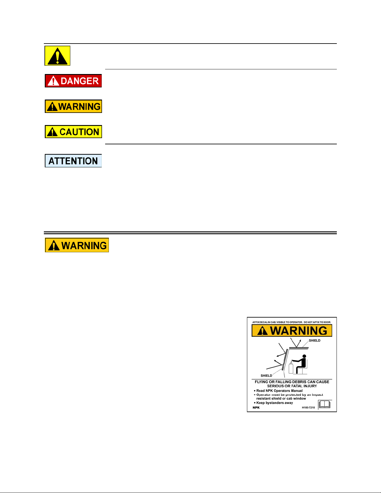
Safety notices in NPK Instruction Manuals follow ISO and ANSI standards for
safety warnings:
DANGER (red) notices indicate an imminently hazardous situation
which, if not avoided, will result in death or serious injury.
WARNING and BASIC OPERATING INSTRUCTIONS decals are included with each
NPK hammer and installation kit. Decals must be installed in the cab, visible to the
operator while operating the hammer.
STAY CLEAR, PRESSURE VESSEL, GAS PRESSURE and TOOL SHARPENING
decals are installed on all NPK hammer models. Keep them clean and visible. NPK will
provide decals free of charge as needed.
WARNING (orange) notices indicate a potentially hazardous situation
which, if not avoided, could result in death or serious injury.
CAUTION (yellow) notices indicate a potentially hazardous situation,
which, if not avoided, may result in minor or moderate injury.
ATTENTION (blue) notices in NPK Instruction Manuals are an NPK
standard to alert the reader to situations which, if not avoided, could
result in equipment damage.
1. Operator and Service personnel must read and understand the NPK INSTRUCTION
MANUAL to prevent serious or fatal injury.
2. FLYING DEBRIS CAN CAUSE SERIOUS OR FATAL INJURY.
Keep personnel and bystanders clear of hammer while in operation.
Do not operate HAMMER without an impact resistant guard between HAMMER
and operator. NPK recommends LEXAN or equivalent material, or steel mesh.
Some carrier manufacturers offer demolition guards for their machine. Check
with the carrier manufacturer for availability. If not
available, please call NPK.
3. Do not hardface or sharpen the tool point with a cutting
torch. Excessive heat from torching or welding can
cause embrittlement, breakage, and flying pieces.
Resharpen by milling or grinding only, using sufficient
coolant.
- 3 -
Page 5

SAFETY
4. Fully extend the tool while charging the HAMMER with nitrogen gas. Be sure that
the retaining pin is installed. STAY CLEAR OF TOOL POINT WHILE CHARGING.
5. Do not disassemble a HAMMER before discharging the hammer gas pre-charge.
6. USE NITROGEN GAS ONLY! Store and handle nitrogen tanks per OSHA
regulations.
7. Avoid high pressure fluids. Escaping fluid under pressure can penetrate the skin
causing serious injury. Relieve pressure before disconnecting hydraulic or other
lines.
8. Operate HAMMER from operator’s seat only.
9. Match HAMMER size to carrier according to NPK recommendations. The carrier
must be stable during hammer operation and during transport.
See CARRIER MACHINE COMPATIBILITY section of the NPK instruction manual.
10. Do not make any alterations to the TOOL without authorization from NPK
Engineering.
11. Use proper lifting equipment and tools when handling or servicing the HAMMER.
12. Wear ear protection and safety glasses when operating the hammer. Consult
OSHA/MSHA regulations when applicable.
13. Beware of flying metal pieces when driving mounting pins.
14. If modifications are to be made, do not alter the HAMMER without authorization
from NPK Engineering!
15. Use only genuine NPK replacement parts. NPK specifically disclaims any
responsibility for any damage or injury that results from the use of any tool or parts
not sold or approved by NPK.
For further safety information, consult the AEM Hydraulic Mounted Breakers Safety
Manual, AEM form MB-140 (NPK P/N H050-9600), which is furnished with every NPK
hammer. To request an additional copy, please contact NPK at 800-225-4379 or
Internet at www.npkce.com.
- 4 -
Page 6

INTRODUCTION
NPK is a leading manufacturer of HYDRAULIC HAMMERS, and has the most complete
product line available anywhere. The success of NPK is due to our commitment to
quality, dependability and long life. The HYDRAULIC HAMMER has many unique
designed features and it is a company philosophy that the NPK HYDRAULIC HAMMER
can be brought to "like new” condition long after competitive products are scrapped.
You can feel confident that you have purchased the best value available.
This comprehensive operator’s manual contains instructions for operating and
maintaining NPK HYDRAULIC HAMMERS. This manual includes helpful information for
obtaining the full potential and efficiency from NPK HYDRAULIC HAMMERS. Please
read this manual thoroughly to understand the NPK HAMMER and its operating
principles before using it.
For additional information or help with any problem encountered, please contact your
NPK authorized dealer.
Whenever repair or replacement of component parts is required, only NPK parts should
be used. NPK is not responsible for failures resulting from substitution of parts not sold
or approved by NPK.
This manual will also assist NPK Dealers and Customers to obtain the longest possible
life from the NPK Demolition Tools.
Customers can use this manual to take corrective action when tool breakage occurs.
Dealers can use this manual to determine if tool breakage can be claimed under
warranty.
Refer to the NPK Demolition Tool Warranty statement found later in this manual for the
specifics of the warranty coverage.
- 5 -
Page 7
CARRIER MACHINE COMPATIBILITY
These carrier weight ranges are intended as a guideline only. Other factors, such as
stick length, counterweights, undercarriage, etc., must be taken into consideration.
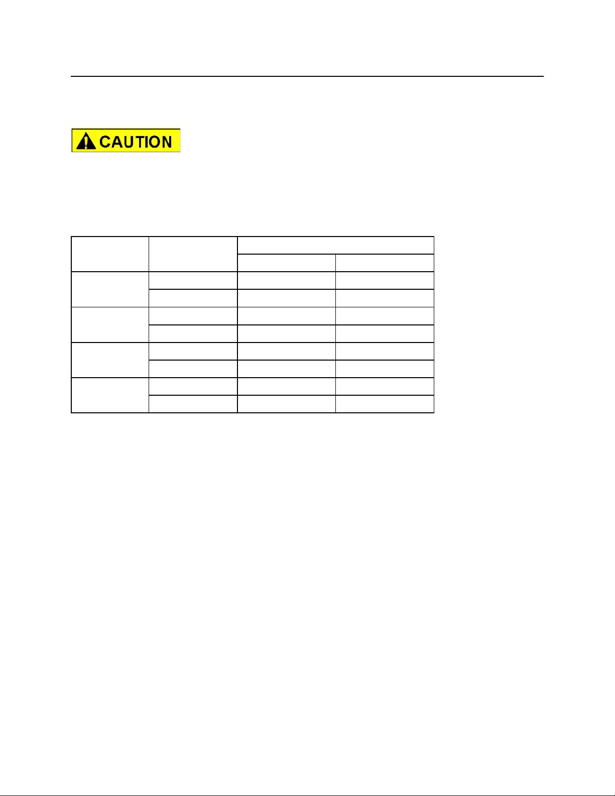
Mounting a HAMMER that is too heavy for the carrier machine
can be dangerous and damage the machine. Verify carrier
stability with hammer before transport or operation.
Mounting a HAMMER that is too small for the carrier machine can damage the
HAMMER, cause tool breakage and void Warranties. Please consult NPK Engineering
for specific detailed information.
CARRIER WEIGHT lbs. (kg)
HAMMER MOUNTING RECOMMENDED RANGE
MODEL STYLE lb (kg)
PH1
PH2
PH3
PH4
*Specifications are subject to change without notice.
Excavator 4,850 - 5,955 (2,200 - 2,700)
Skid Steer 4,850 - 5,955 (2,200 - 2,700)
Excavator 5,955 - 8,820 (2,700 - 4,000)
Skid Steer 5,955 - 8,820 (2,700 - 4,000)
Excavator 8,820 - 13,228 (4,000 - 6,000)
Skid Steer 8,820 - 13,228 (4,000 - 6,000)
Excavator 13,228 - 19,842 (6,000 - 9,000)
Skid Steer 13,228 - 19,842 (6,000 - 9,000)
- 6 -
Page 8
HAMMER SPECIFICATIONS
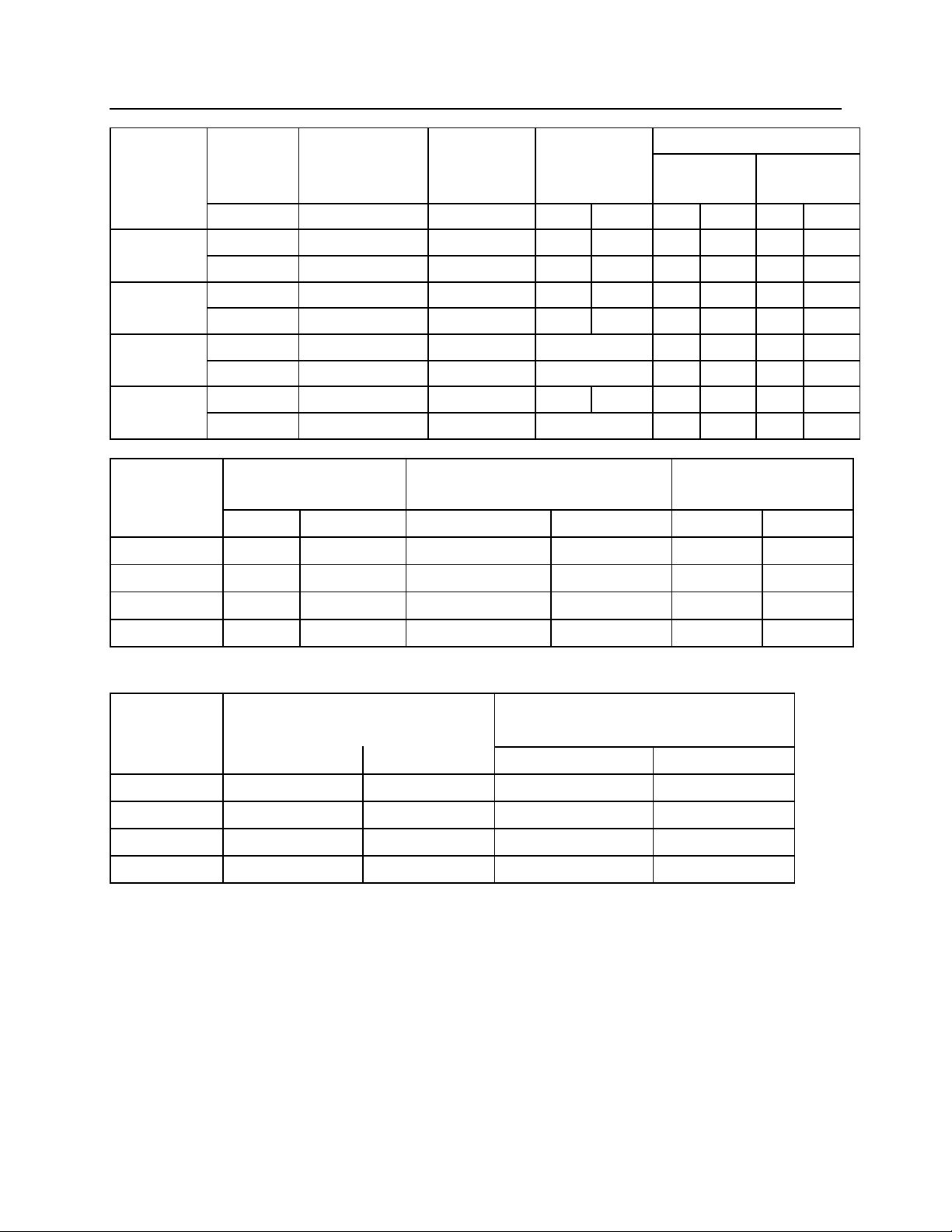
HAMMER IMPACT FREQUENCY MOUNTING WORKING TOOL
MODEL ENERGY STYLE WEIGHT DIA. WORKING
CLASS LENGTH
ft. lb. bpm lbs. (kg) in. (mm) in. (mm)
PH1
PH2
PH3
PH4
HAMMER OIL FLOW HYDRAULIC OPERATING MINIMUM CIRCUIT
MODEL PRESSURE1 RELIEF2
350 550 - 1,100 Excavator 423 (192) 2.24 (57) 14.0 (356)
Skid Steer 674 (306)
500 500 - 1,200 Excavator 487 (221) 2.60 (66) 15.1 (384)
Skid Steer 735 (333)
750 500 - 1,150 Excavator 825 (374) 2.99 (76) 16.5 (419)
Skid Steer N/A
1300 400 - 1,000 Excavator 1,064 (483) 3.39 (86) 18.5 (469)
Skid Steer N/A
gpm
PH1
PH2
PH3
PH4
NITROGEN GAS PRECHARGE
HAMMER AT AMBIENT TEMPERATURE
MODEL
*psi (bar) *psi (bar)
PH1
PH2
PH3
PH4
*The gas charge tolerances plus 0, minus 25 psi (2 bar).
*Specifications subject to change without notice.
7 - 15
7 -16
12 - 27
13 - 32
(cold before operating)
175 (12) 220 (15)
175 (12) 220 (15)
175 (12) 220 (15)
175 (12) 220 (15)
(lpm)
(25 - 55)
(25 - 60)
(45 - 100)
(50 - 120)
psi
2,175 - 2,465
2,175 - 2,465
2,175 - 2,465
2,175 - 2,465
NOTES:
(bar)
(150 - 170)
(150 - 170)
(150 - 170)
(150 - 170)
AT OPERATING TEMPERATURE (hot,
after 1 to 2 hrs. operation)
psi
2,965
2,965
2,965
2,965
(bar)
(204)
(204)
(204)
(204)
1. Hydraulic operating pressure maximum is inlet pressure at the hammer with the oil at
operating temperature and with the gas charge set at the hot operating pressure. See
CHECKING THE HYDRAULIC PRESSURES section in the Service Manual.
2. Circuit relief pressure is at least 500 psi (35 bar) above hammer operating pressure.
3. Cold gas charge is the initial set with the hammer at ambient temperature.
4. Hot gas charge is checked after 1 to 2 hours of running and with a system oil temperature of
140 to 180F (60
to 80C). This is the preferred check.
5. Pressures listed are the maximum allowed. Use tolerance of minus 25 psi (2 bar).
- 7 -
Page 9
STRUCTURE
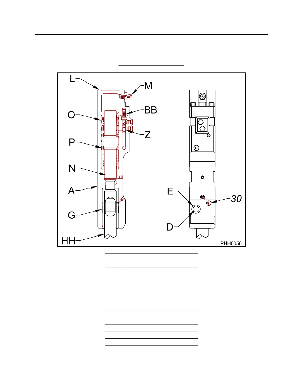
STRUCTURAL DRAWING
MODELS PH1 – PH4
30 GREASE FITTING
A MAIN BODY
BB PLUNGER
D RETAINING PIN
E RETAINING RING
G TOOL BUSHING
HH TOOL
L GAS HEAD
M CHARGE VALVE
N PISTON
O MAIN BODY SLEEVE (A)
P MAIN BODY SLEEVE (B)
Z VALVE SPOOL
- 8 -
Page 10
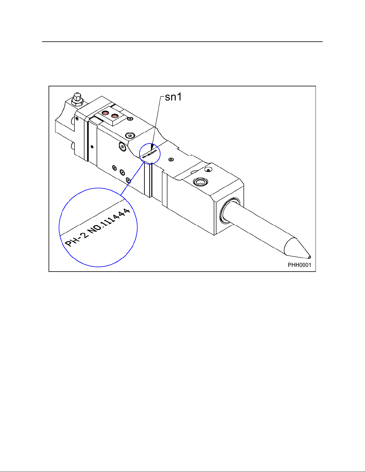
HAMMER SERIAL NUMBER LOCATION
SERIAL NUMBER LOCATION (sn1)
- 9 -
Page 11
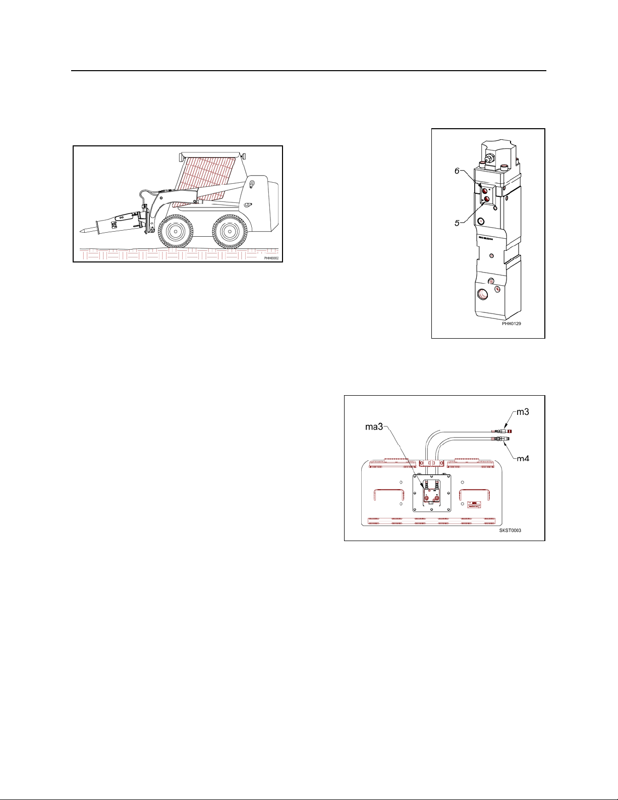
HYDRAULIC INSTALLATION
NPK can produce INSTALLATION KITS for virtually all compatible backhoe loaders,
excavators, and skid steers. Complete parts and instructions for the hydraulic
installation of the NPK HYDRAULIC HAMMER including valves and/or controls, hoses
and fittings, boom and stick tubing, and clamps are provided.
HAMMER LINES (BACKHOE and
EXCAVATOR)
Typically, the pressure line is arranged on the left side of the
boom and routed to the hammer “IN” port (6) and the return line
is routed from the hammer “OUT” port (5) on the right side. Flow to the hammer is
controlled from an auxiliary valve on the carrier or from an NPK supplied valve.
Hydraulic oil, generally, is routed back to the tank thru the carrier’s oil cooler and filter.
HAMMER LINES (SKID STEER)
Flow to the hammer (m3) is directed from an
auxiliary valve on the skid steer. NPK hammer
ports are marked “IN” and “OUT”. On skid
steers where the auxiliary flow is excessive for
the hammer model, a flow control valve (ma3) is
recommended. Return oil (m4) is routed back to
tank through the skid steer return circuit.
HAMMER CONTROL VALVE
NPK uses two general types of control systems,
depending upon the carrier model:
1. CONTROL SYSTEM USING THE CARRIER AUXILIARY OR SPARE VALVE
SECTION.
This type of installation utilizes an existing carrier valve. Any additional parts, such
as a mechanical linkage, hydraulic pilot actuators, flow control valves, etc., are
furnished in the NPK HYDRAULIC INSTALLATION KIT. Special hydraulic pressure
control valves are not required. The NPK HYDRAULIC HAMMER operating
pressure is self-regulating.
2. CONTROL SYSTEM USING THE NPK MULTIVALVE.
For carriers not equipped with a suitable auxiliary or spare valve section, the NPK
HYDRAULIC INSTALLATION KIT includes a solenoid operated, priority flow control
valve to operate the NPK HYDRAULIC HAMMER. The NPK MULTIVALVE is
specifically designed for the operation of boom mounted attachments.
- 10 -
Page 12
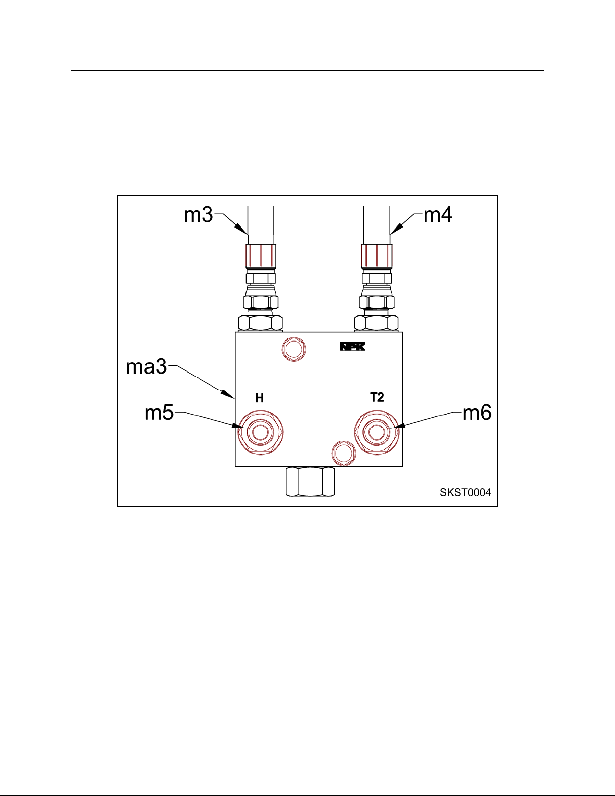
HYDRAULIC INSTALLATION
SKID STEER HAMMER FLOW CONTROL VALVE (OPTIONAL)
Be sure that the pressure (m3) and return lines (m4) are properly routed.
Inlet pressure connects to port “P” on the NPK flow control valve (ma3). Regulated flow
from valve port “H” (m5) connects to the “IN” port on the NPK hammer. The “OUT” port
on the hammer connects to port “T2” (m6) on the flow control valve. “T1” connects to
the return line (m4) on the skid steer.
- 11 -
Page 13

HYDRAULIC INSTALLATION
PREVENTION OF CONTAMINATION
1. A hydraulic hammer is harder on oil than using a bucket, so the oil is apt to
deteriorate and breakdown sooner. Neglect of the oil system can not only damage
the hydraulic hammer but also cause problems in the carrier which could result in
damaged components. Care should be taken to check for contamination of the oil
and to change it if it is found contaminated. Oil sampling at regular intervals is
highly recommended.
When the hydraulic oil shows low viscosity and bubbles, this indicates that the oil
is deteriorated. If the oil is dark brown and gives off an offensive odor, it is
severely deteriorated. Change the oil immediately!
When the oil is clouded, or the oil filter has become clogged, it indicates that the
oil is contaminated. Change the oil immediately!
To change the contaminated hydraulic oil, drain the hydraulic system completely
and clean components. Do not mix new oil with the old.
2. Do not allow any contaminat ion to mix with the oil. Take special care in preventing
contamination from entering the hydraulic system through the hose or tube
connection when changing the hydraulic hammer with the bucket.
3. Low oil level will cause heat build-up, resulting in deterioration of the oil. Also, it may
cause cavitation due to air mixing with the oil, leading to a damaged hydraulic
hammer and carrier components. Keep the oil at the proper level at all times.
4. Do not use the hydraulic hammer at an operating temperature higher than 180°F
(80°C). The proper operating oil temperature range is between 120°F (50°C) and
180°F (80°C). Since contaminated cooler fins causes reduced efficiency of the
cooler, keep the cooler fins clean at all times. Check the hydraulic oil cooling system
to be sure it is working effectively. The use of a heat gun is the best way to evaluate
if the cooler is working properly.
5. Water in the hydraulic oil will lead to damage of the hydraulic hammer and carrier.
Drain off water and foreign matter from the hydraulic tank at specified intervals.
When out of service, the hydraulic hammer should be stored indoors.
CHANGING THE FILTER ELEMENT AND HYDRAULIC OIL
Change the filter element and hydraulic oil at the intervals described in the operation
manual of the skid steer or excavator, when using a hydraulic implement. Another
method is to set up an oil sampling schedule and change accordingly.
- 12 -
Page 14
HYDRAULIC INSTALLATION
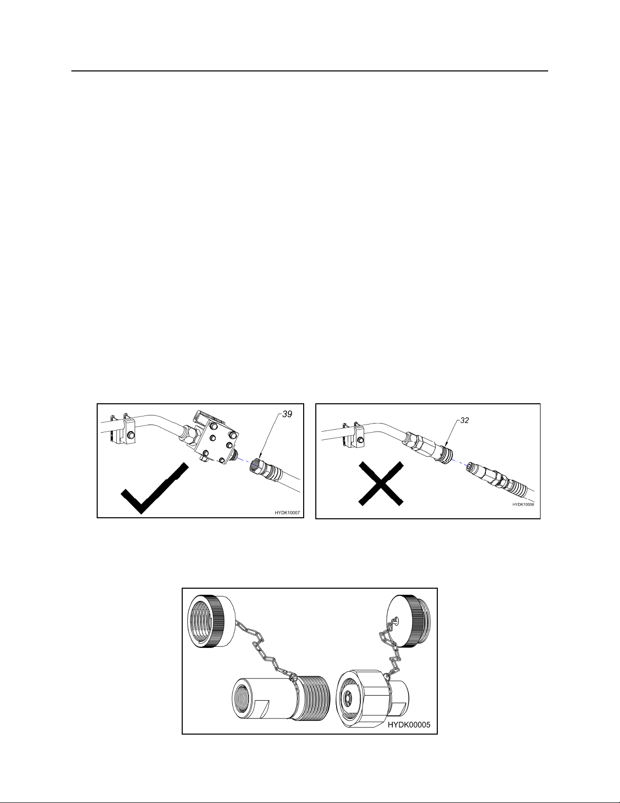
HYDRAULIC QUICK DISCONNECTS
NPK recommends against the use of non-NPK quick
disconnects on hydraulic circuits operating NPK Products.
1. The hydraulic pulsations caused by hydraulic hammer operating can cause internal
pieces of non-NPK quick disconnect to disintegrate. These pieces would migrate
into the hammer, causing damage.
2. If quick disconnects are not used when the hammer is removed from the excavator,
the hose ends should be capped to keep them clean. If this is not done,
contamination in the hose ends will be flushed into the hammer when re-connected.
This, again, can cause damage.
3. Most quick disconnects create a restriction in the circuit. NPK Hammers are not
backpressure sensitive, but restrictions cause unnecessary heating of the oil. Also,
the pressure required to operate the hammer, plus the restriction in the quick
disconnects may push an older, low pressure, carrier machine to the limit of its
hydraulic system. This would interfere with proper hammer operation. However,
the NPK approved quick disconnects are properly sized so that the hammer
operation is not affected.
APPROVED CONNECTION (39)
NOT RECOMMENDED CONNECTION
Non-NPK Quick Disconnects (32)
NPK APPROVED CONNECTION QUICK DISCONNECTS
CONTACT YOUR NPK DEALER FOR ADDITIONAL INFORMATION ABOUT
NPK QUICK DISCONNECTS (DX)
- 13 -
Page 15
HYDRAULIC INSTALLATION
HYDRAULIC QUICK DISCONNECTS
If hydraulic quick disconnects are used with the NPK Hammer, it is recommended that
the following precautions be followed.
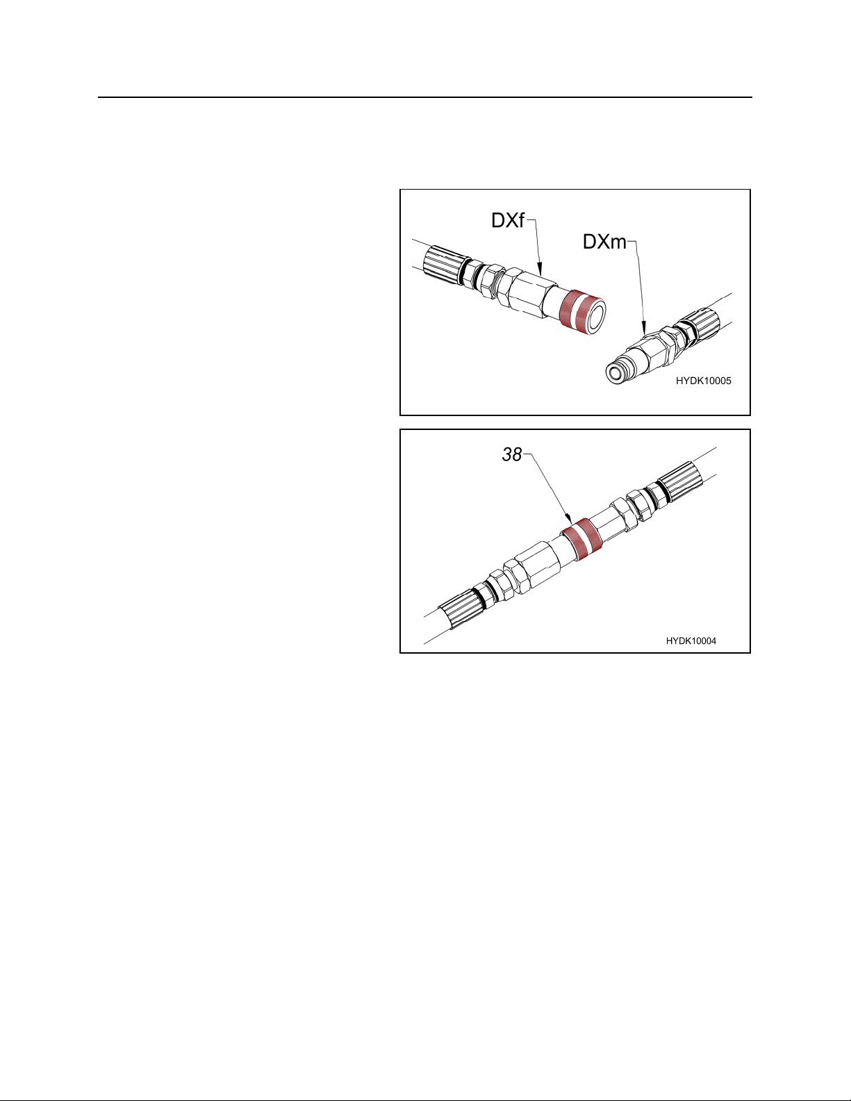
1. Periodic inspection of both male
(DXm) and female (DXf) ends is
recommended to ensure the
couplers are in good working
condition. Failure to inspect
couplers may result in pieces from
a damaged or failed coupler to be
injected into the hammer or parts
of the coupler returned to the
machine.
2. Check for dirt, dust, and debris on
both male and female couplers
before coupling.
3. Be sure that the couplers are
completely seated together (38).
4. When replacing couplers, be sure
that couplers are replaced as a set,
male and female. Do not use one
new end and one used end.
- 14 -
Page 16
MOUNTING INSTALLATION
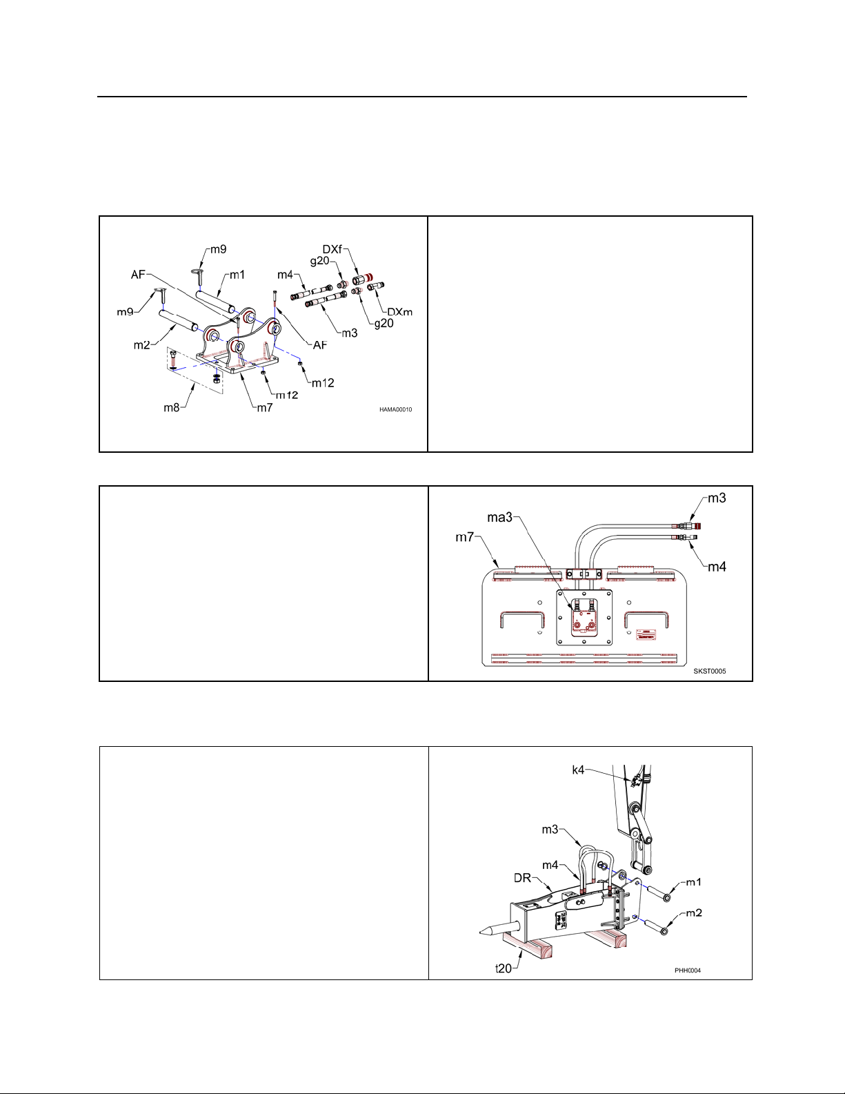
NPK Mounting Installation Kits include the parts required to adapt the NPK HYDRAULIC
HAMMER to the carrier. NPK mounting kits include the hammer mounting bracket,
mounting pins (optional), flow control valve (optional), and hoses to connect to the
carrier hydraulic system (optional).
BACKHOES and EXCAVATORS
SKID STEERS
NPK Mounting Installation Kits for skid
steers include parts required to adapt the
NPK HYDRAULIC HAMMER to the
carrier. NPK mounting kits include the
hammer mounting bracket (m7), and
hoses (m3 and m4) to connect to the
carrier hydraulic system. The flow control
valve (ma3) is optional.
AF Hex Head Cap Screw (if required)
g20 Male Adapter (if required)
m12 Hex Nut (if required)
DXm Male Quick Disconnect (if required)
DXf Female Quick Disconnect (if
required)
m1 Stick Pin (if required)
m2 Link Pin (if required)
m3 (Whip) Pressure Hose
m4 (Whip) Return Hose
m7 Top Bracket
m8 Hammer Bolt Package
m9 Klik Pin (if required)
REMOVAL FROM THE CARRIER
BACKHOES and EXCAVATORS
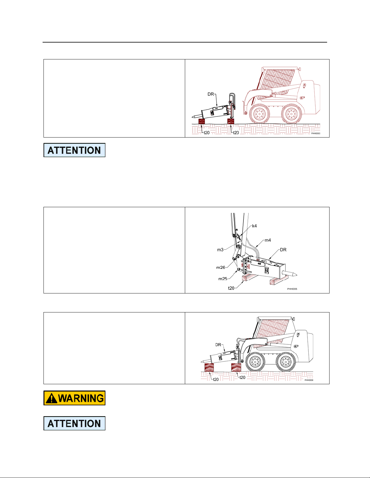
1. Close pressure and return line shut-off
valves (k4) if available.
2. Disconnect hydraulic hoses (m3 and
m4) before laying the hammer down.
3. Cap the pressure and return lines on
the carrier and connect the hammer
whip hoses to the hammer bracket.
4. Position the hammer (DR) horizontal
on wood blocks (t20) and remove stick
(m1) and link (m2) pins.
- 15 -
Page 17
MOUNTING INSTALLATION
REMOVAL FROM THE SKID STEER
1. Position the hammer (DR) horizontally
onto the ground or wood blocks (t20)
as shown.
2. Disconnect both inlet and outlet hoses.
3. Unlatch the mechanism holding the
hammer bracket to the carrier’s
coupler plate. (Consult the machine
manufacturer’s operator/instruction
manual for this procedure.
The tool end of the hammer should be set lower than the head end to prevent
moisture from entering the hammer through the tool area.
MOUNTING TO THE CARRIER
BACKHOES and EXCAVATORS
1. Place the hammer assembly (DR)
horizontally on wood blocks (t20) as
shown.
2. Align the stick pin bore (m26). Install
the stick pin. Then align the link pin
bore (m25).
3. Connect the pressure side hose (m3)
and the return side hose (m4).
4. Open the shut-off valves (k4) if
available.
MOUNTING TO THE SKID STEER
1. Place the hammer (DR) horizontally
onto wood blocks (t20) as shown.
2. Align the carrier’s coupler plate with
the hammer bracket. Couple the two
per the machine manufacturer
recommendations.
3. Connect the hoses.
Consult the skid steer manufacturer’s operators manual to
review the mounting and removal process!
The hydraulic lines must be handled carefully and sealed to
prevent contamination from entering the hammer or the
carrier’s hydraulic system.
- 16 -
Page 18
LUBRICATION
GREASING PROCEDURE
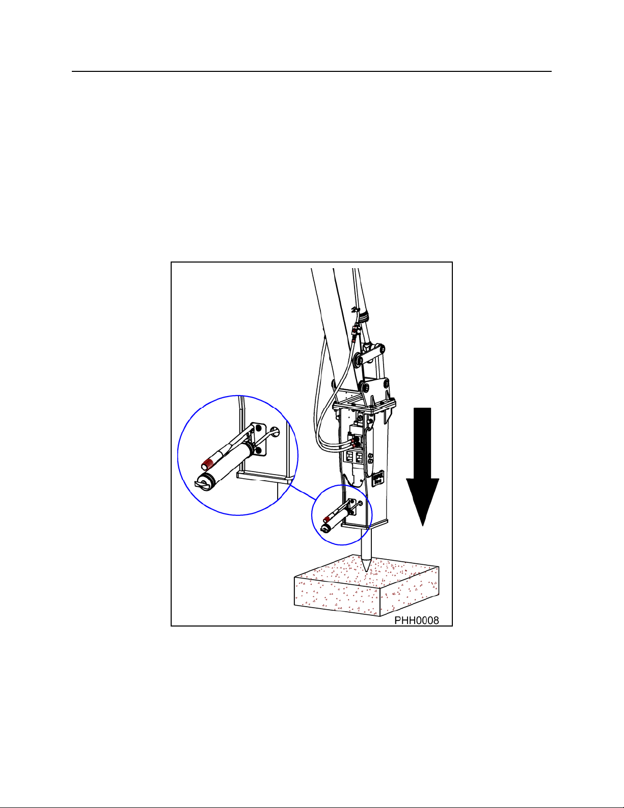
1. Place the hammer in a vertical position, applying enough down force to push the tool
up into the hammer.
2. Turn the machine off.
3. Grease the hammer until grease begins to come out around the tool and lower
bushing.
4. Grease hammer at least once an hour. See “Correct Grease and Grease Intervals”
for a more exact greasing procedure.
APPLY DOWN FORCE TO PUSH TOOL UP INTO HAMMER
NOTE: USE A GOOD QUALITY EP #2 LITHIUM BASED GREASE WITH WEAR
INHIBITING ADDITIVES, SEE PAGES 18 AND 19.
- 17 -
Page 19

LUBRICATION
CORRECT GREASE AND GREASE INTERVALS
Proper hammer maintenance requires a sufficient supply of the correct grease to the
tool (chisel). The tool must be pressed against a hard surface until it stops up inside the
hammer. This prevents grease from entering piston impact area and ensures proper
distribution of grease between the tool and tool bushings.
GREASE INTERVALS
If the hammer is not connected to an Auto Lube System, see page 19, the hammer
must be greased at regular intervals to get the best life from the tool and tool bushings.
There are two ways to determine grease intervals:
First, grease the hammer at the beginning of the job until grease comes out between
the tool and the lower tool bushing. Run the hammer until the shank of the tool starts to
look dry. This determines the time interval for the greasing of this particular hammer on
this particular job. Typically, this is 1 to 4 hours. Also, note the amount of grease
needed to re-grease the tool. This gives you the amount of grease and how often it
must be applied. An example would be that a particular hammer, on a particular job,
requires half a tube of grease every 3 hours. This would be the greasing schedule you
would set up. If this hammer was moved to another job, another grease schedule may
have to be determined.
Second, if you can’t control the grease schedule, such as rental units, then have the
operator grease the hammer once every hour of hammer operation. Again, grease the
hammer until grease comes out between the tool and tool bushing. This is usually more
often than required, but is far cheaper than replacing prematurely worn tools and tool
bushings.
CORRECT GREASE
The type of grease used is very important. NPK recommends a lithium soap base EP
(Extreme Pressure) NLGI #2 Grease, with Moly (Molybdenum Disulfide) or other
surface protecting additives. A high drop point 500°F (260°C) grease is desirable.
There are many manufacturers of grease that meet NPK’s recommendations. NPK
does not endorse any one brand as being superior to another. If you or your customers
question a brand to be used, please call the NPK Service Department at 800-225-4379.
- 18 -
Page 20
LUBRICATION
CORRECT GREASE FOR HYDRAULIC HAMMERS
NPK HAMMER GREASE
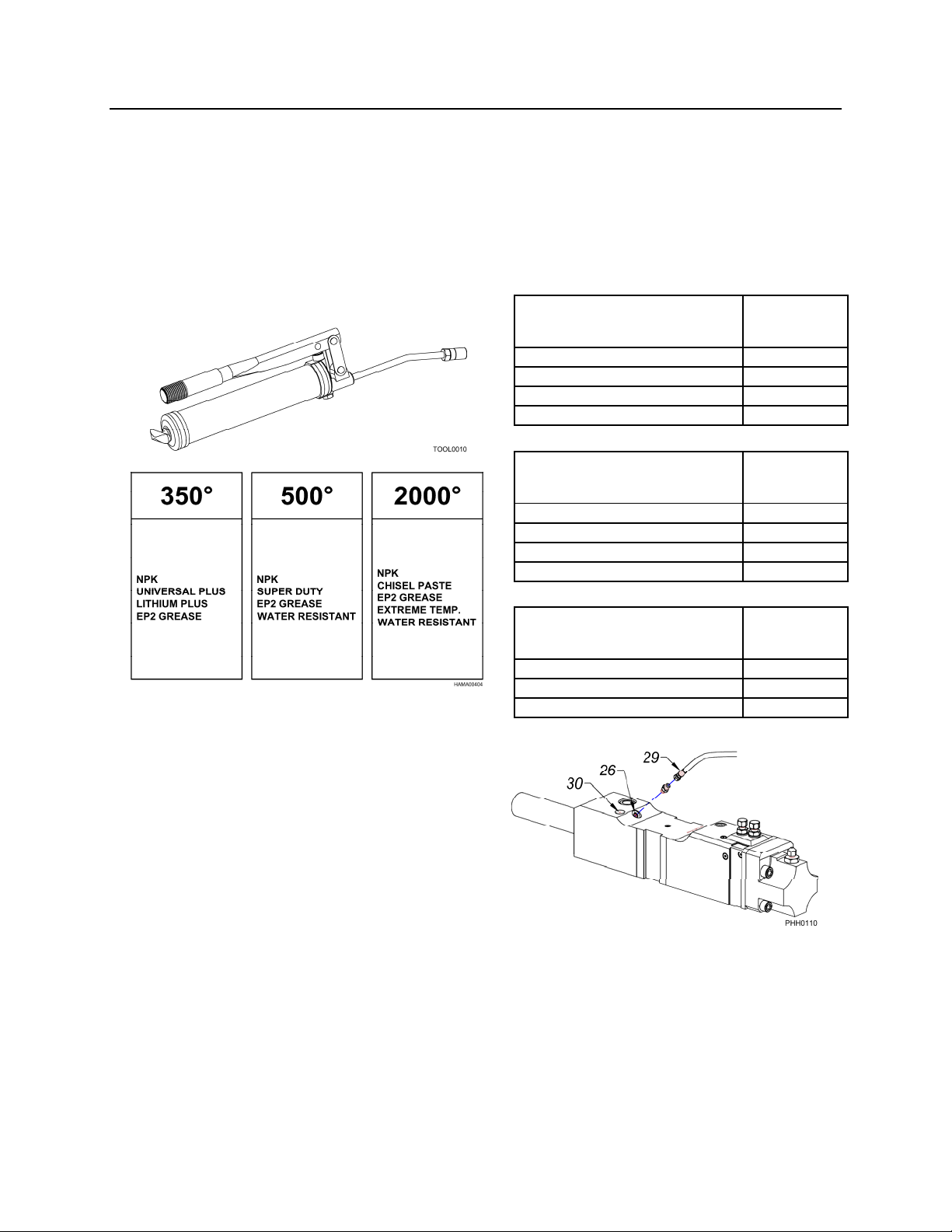
NPK now offers hammer grease specially formulated to meet severe job requirements.
The grease is available in three different temperature ranges - 350°, 500°, and 2000°.
Universal Plus and Super Duty are lithium soap based products that resists washout
and contain NPK-10 additive for surface protection in friction affected areas.
Chisel Paste is an aluminum complex soap base with 12% graphite and copper
additives for extreme operating conditions.
UNIVERSAL PLUS NPK PART
350 deg NUMBER
14 oz. (.397 kg) CARTRIDGE G000-1010
120 lb. (54 kg) KEG G000-1020
35 lb. (16 kg) PAIL G000-1030
400 lb. (181 kg) DRUM G000-1040
AUTO LUBE SYSTEMS
14 oz. (.397 kg) CARTRIDGE G000-1011
120 lb. (54 kg) KEG G000-1021
35 lb. (16 kg) PAIL G000-1031
400 lb. (181 kg) DRUM G000-1041
14 oz. CARTRIDGE G000-1050
35 lb. (16 kg) PAIL G000-1060
400 lb. (181 kg) DRUM G000-1070
SUPER DUTY NPK PART
500 deg NUMBER
CHISEL PASTE NPK PART
2000 deg NUMBER
An automatic greasing system is
recommended to reduce hammer tool and
tool bushing wear. THE NPK AUTO LUBE
SYSTEM is designed to automatically
provide a continuous supply of grease to
the hammer tool and tool bushing –
increasing tool and tool bushing life by
reducing wear. The AUTO LUBE pump is
capable of pumping EP2 grease in cold
weather. The pump output is adjustable
according to the requirements of the
hammer model and to compensate for tool
bushing wear.
26 – AUTO LUBE PORT
29 – GREASE LINE
30 – GREASE FITTING FOR MANUAL
LUBRICATION
NPK GH Series hammer models have a connection port (26) for an automatic greasing
system. Refer to the NPK AUTO LUBE Instruction Manual for details. If the AUTO
LUBE is not used, you can grease unit through fitting (30) as shown.
- 19 -
Page 21
LUBRICATION
AUTO LUBE GREASE LINE PRE-FILLING
It is mandatory that the supply line from the Auto Lube main pump to the connection on
the hammer is primed with grease before it is used. Failure to do this will result in no
grease being administered to the hammer tool for two to three hours. This can and will
result in severe galling of the tool and tool bushing.
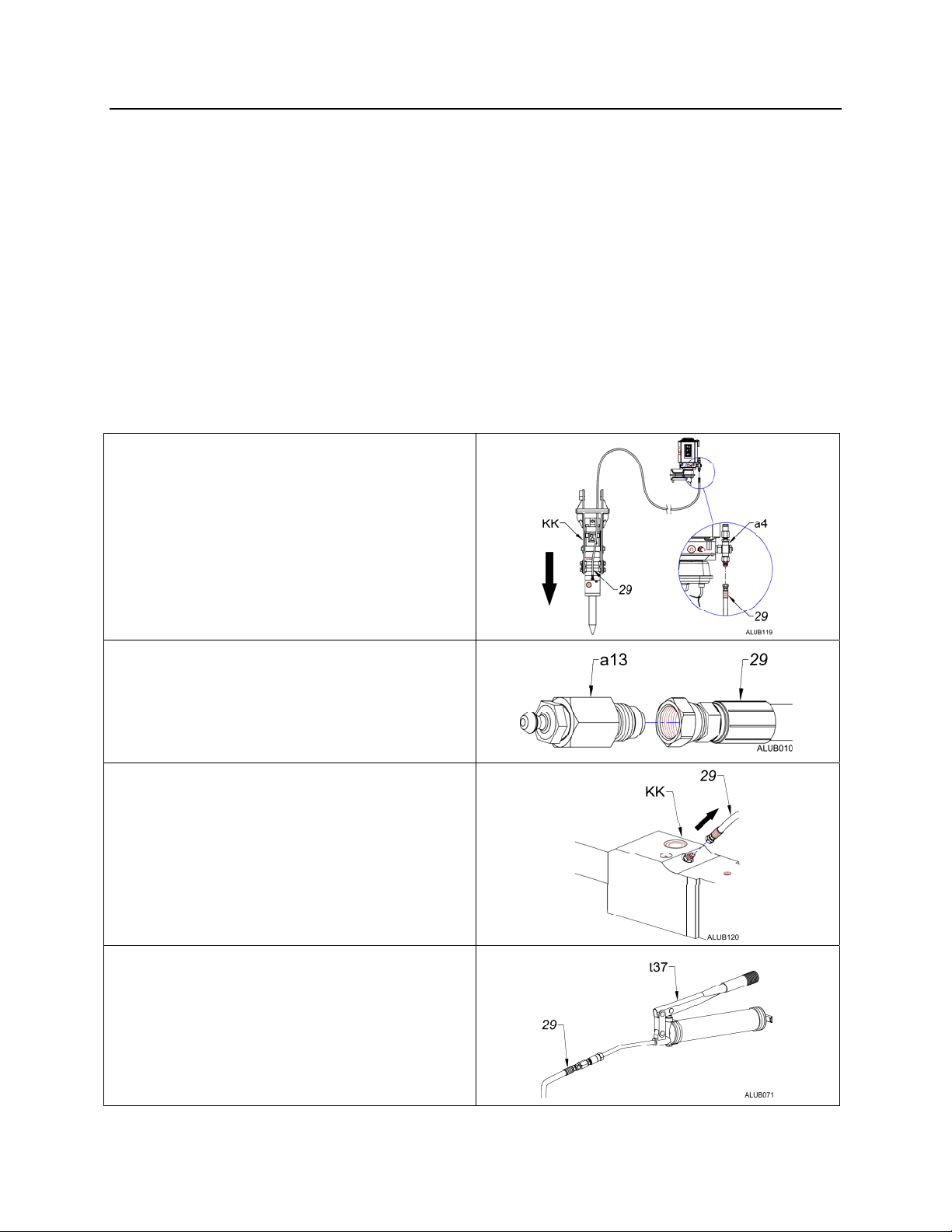
PRIMING THE GREASE LINE
1. Place the hammer (KK) in a vertical position, applying enough down force to push
the tool up into the hammer.
2. Turn the machine off.
3. Fill the NPK Auto Lube pump reservoir with a power greaser through the fill fitting on
the side of the pump, or from the top by removing the fill cover. Use a premium
quality grade EP-2, high temperature grease with wear inhibiting additive.
4. Disconnect the grease line (29) from
the Auto Lube main pump cartridge
(a4).
5. Install part number G100-8050 hose fill
adapter (a13) onto the #6 JIC end of
the grease line (29) previously
removed.
6. Remove the grease line (29) at the
hammer (KK).
7. Attach a grease gun (t37) or power
greaser to the grease line (29) leading
to the hammer.
- 20 -
Page 22
LUBRICATION
AUTO LUBE GREASE LINE PRE-FILLING
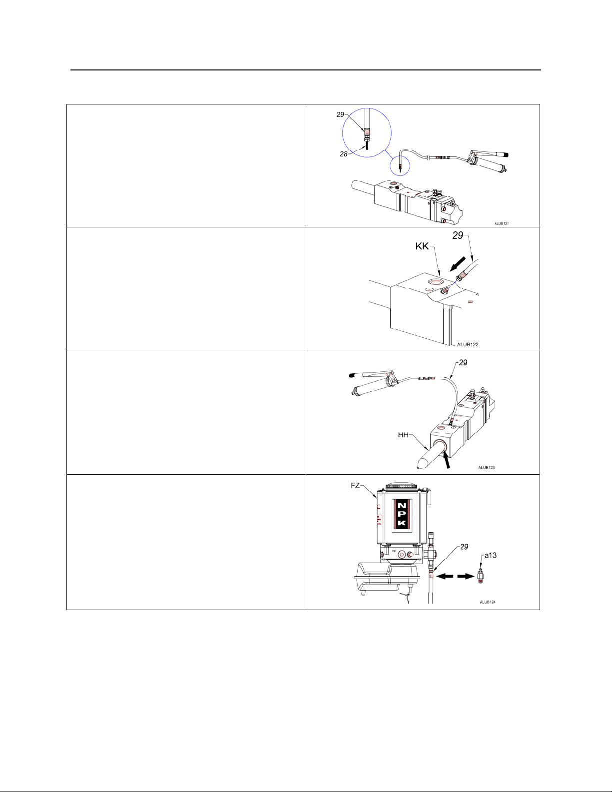
8. Pump grease through the grease line
(29) until a steady stream of grease
(28) is realized at the opposite
(hammer) end.
9. Re-attach the grease line (29) to the
hammer (KK).
10. Pump twenty more shots of grease
into the grease line (29). This will
prime the hammer cavity and pre-lube
the tool. Look for grease coming out
around the tool (HH) at the tool
bushing (see arrow).
11. Remove the hose fill adapter (a13)
and re-connect the grease line (29) to
the Auto Lube pump (FZ).
NOTE: If the Auto Lube has run out of grease, the above procedure should be
used to purge all the air out of the line (29) before using the hammer.
Failure to do this will result in an intermittent supply of grease to the
hammer.
- 21 -
Page 23
LUBRICATION
AUTO LUBE GREASE LINE PRE-FILLING
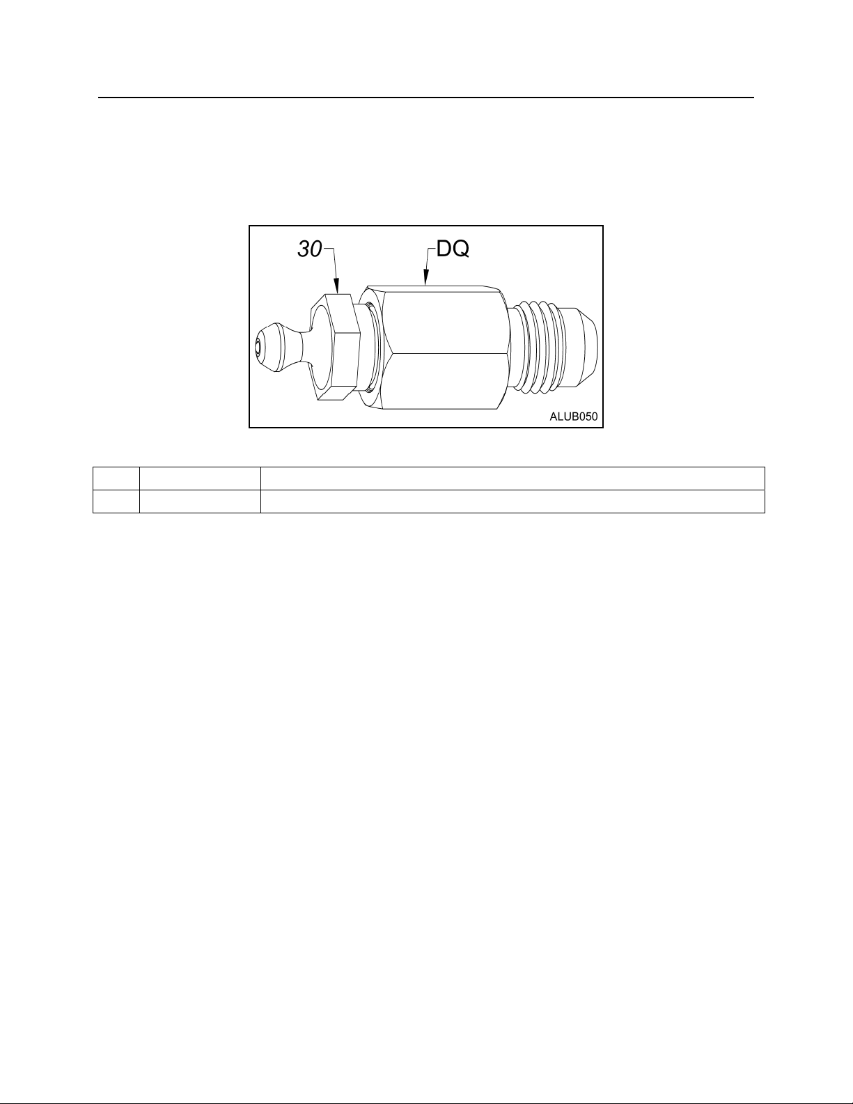
G100-8050 Hose Fill Assembly
30
B160-4010 Grease Fitting - ¼” NPT male
DQ K301-6620 Male x Female Adapter - #6 JIC male x ¼” NPT Female
- 22 -
Page 24
LUBRICATION
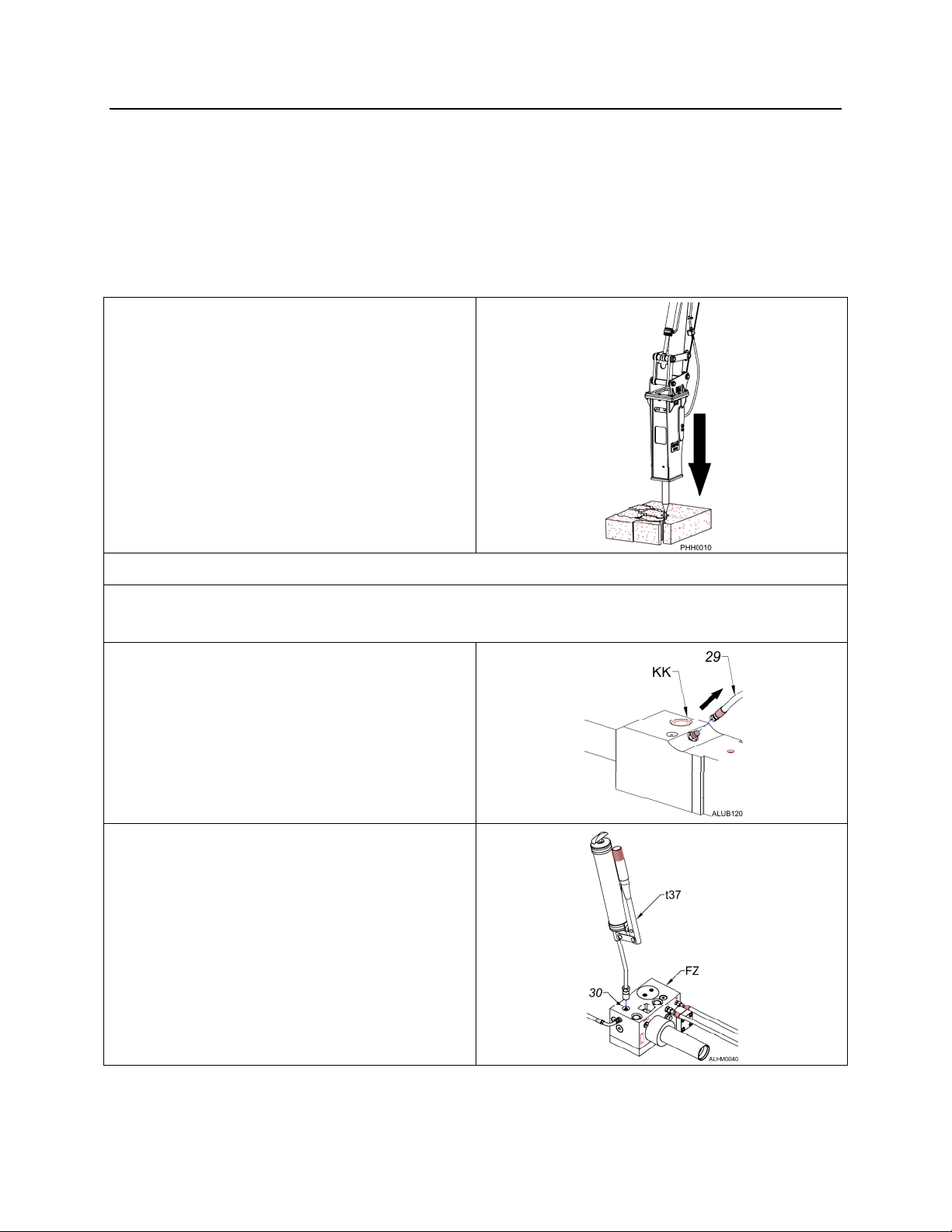
HAMMER MOUNTED AUTO LUBE GREASE LINE PRE-FILLING
It is mandatory that the supply line from the Auto Lube main pump to the connection on
the hammer is primed with grease before it is used. Failure to do this will result in no
grease being administered to the hammer tool for a period of time. This can and will
result in severe galling of the tool and tool bushing.
PRIMING THE GREASE LINE
1. Place the hammer in a vertical position,
applying enough down force to push
the tool up into the hammer.
2. Turn the machine off.
3. Make sure there is a full grease cartridge installed in the Auto Lube assembly. Use
a premium quality grade EP-2, high temperature grease with wear inhibiting additive.
4. Remove the grease line (29) at the
hammer (KK).
5. Attach a grease gun (t37) or power
greaser to the grease fitting (30) on the
front side of the pump assembly (FZ).
- 23 -
Page 25
LUBRICATION
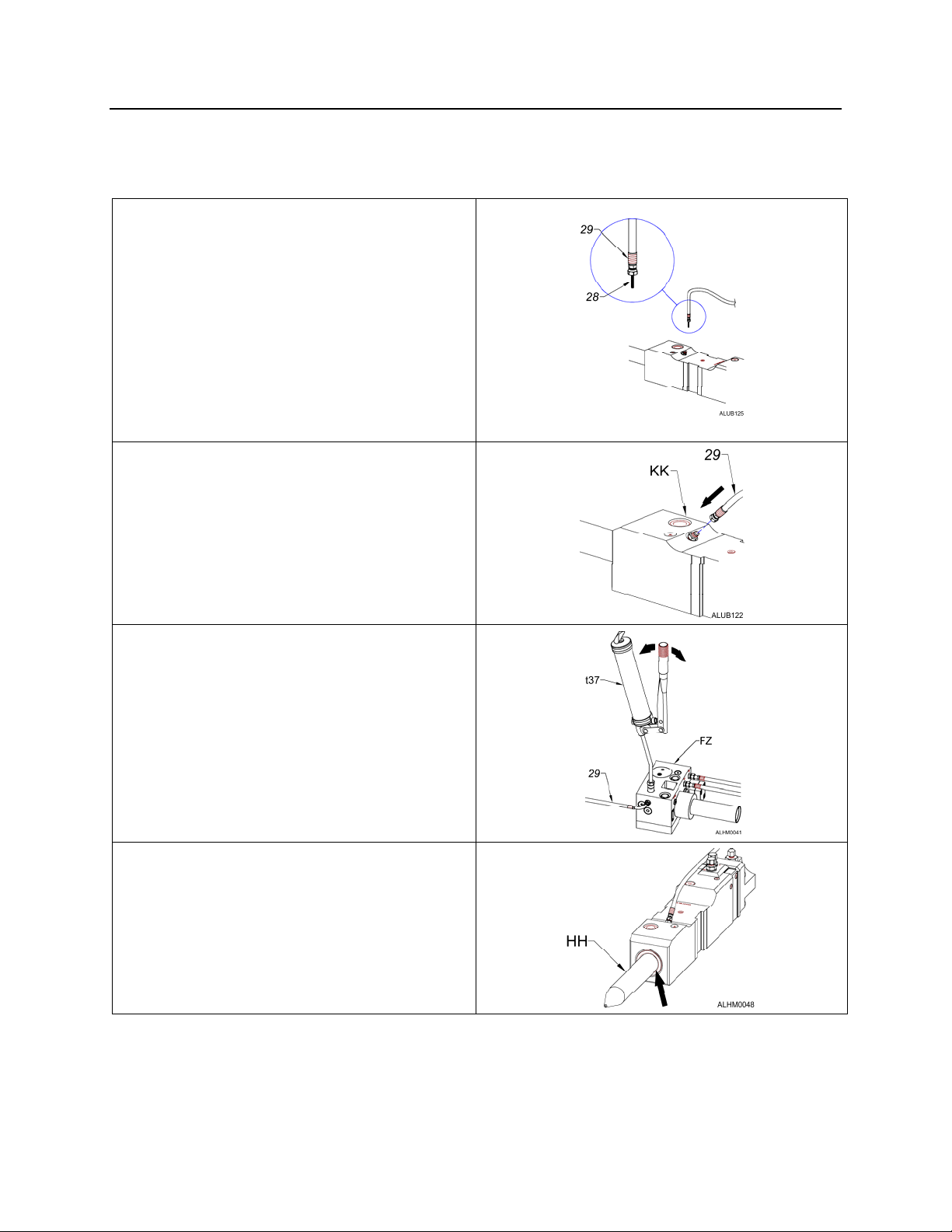
HAMMER MOUNTED AUTO LUBE GREASE LINE PRE-FILLING
PRIMING THE GREASE LINE
6. Pump grease through the pump to the
grease line (29) until a steady stream
of grease (28) is realized at the
opposite (hammer) end.
6a. It is also possible to purge the grease
line to the hammer by disconnecting it
at the hammer then pumping grease
through the grease fitting provided on
the grease pump assembly.
7. Re-attach the grease line (29) to the
hammer (KK).
8. Pump twenty more shots of grease
using the grease gun (t37) or power
greaser into the pump assembly (FZ).
This will prime the hammer cavity and
pre-lube the tool.
9. Look for grease coming out around
the tool (HH) at the tool bushing (see
arrow).
NOTE: If the Auto Lube has run out of grease, the above procedure should be
used to purge all the air out of the line (29) before using the hammer.
Failure to do this will result in an intermittent supply of grease to the
hammer.
- 24 -
Page 26

LUBRICATION
LUBRICANT TERMS AND DEFINITIONS
TERM DEFINITION
ADHESIVE
ANTI WEAR AGENTS
COHESIVE
CONSISTENCY
CONTAMINATION
DROPPING POINT
EXTREME PRESSURE
AGENTS
FILM STRENGTH
FRICTION
GALLING
LUBRICATION
NLGI
OILINESS
PUMP
The ability of grease, gear lubricant or oil to cling to
metal.
Used to help combat metal-to-metal contact, thus
reducing wear.
The ability of grease, gear lube or oil to cling to itself,
thus resisting tearing apart.
Consistency of grease is its hardness or firmness. It is
determined by the depth in millimeters to which the cone
of a penetrometer sinks into a sample under specified
conditions. Consistency of grease may be influenced by
the type and amount of thickener, viscosity of oil, working
and other factors.
Foreign material that could damage a part.
The minimum temperature at which the oil in grease
subjected to heat begins to actually drip and breakdown.
Additives that under extreme pressure form an adherent
film on metal surfaces, thus forming a film of protection.
Film strength is defined as the tendency of oil molecules
to cling together. It is the ability of those molecules to
resist separation under pressure between two metals and
to hold these metal surfaces apart.
The resistance to fluid flow in a hydraulic system. (An
energy loss in terms of power output.)
Surface damage on mating, moving metal parts due to
friction. A severe form of adhesive wear.
Use of a substance (grease, oil, etc.) to reduce friction
between parts or objects that move against each other.
A rating given to grease from the National Lubricating
Grease Institute. This rating determines the hardness of
the grease and goes on from a 000 to a 6 rating. Most
different brands of grease are NLGI #2 rated.
Oiliness is measured of the coefficient of friction of a
lubricant. Oiliness or lubricity depends on the adhering
characteristics of the oil. It is determined by the attraction
between the molecules of the oil and the molecules of
another material. Of two oils having the same viscosity
but different degrees of fluid friction, the one with the
lower friction index has the higher degree of oiliness.
A device which converts mechanical force into hydraulic
fluid power. Basic design types are gear, vane, and
piston units.
- 25 -
Page 27

LUBRICATION
LUBRICANT TERMS AND DEFINITIONS
TERM DEFINITION
RESERVOIR
VIBRATION
VISCOSITY
A container for keeping a supply of working fluid in a
hydraulic system.
A quivering or trembling motion.
Viscosity is the actual SAE weight of the product.
Example motor oils come in 10, 20, 30, 40, 50 and 15/40
SAE weight. The viscosity designation of a lubricant
indicates its internal resistance to flow.
- 26 -
Page 28
AUTO LUBE / UNDERWATER PORT
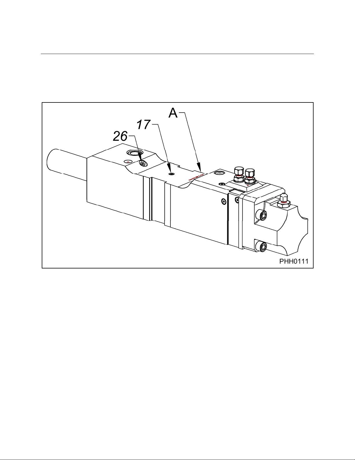
IDENTIFICATION
NPK PH Series Hammers are equipped with two ports on the main body (A) used in
adapting for AUTO LUBE and underwater use. The air port (17) will allow the
connection of an air line that will allow the hammer to be used underwater. The grease
port (26), located in line with the air port, will allow for AUTO LUBE connection.
- 27 -
Page 29
START-UP OPERATION
HAMMERS THAT ARE NEW, REBUILT, OR
HAVE BEEN INACTIVE
Before using a new hammer for the first time, the first time after rebuild, or a
hammer that has been inactive for a long period of time:
1. Check the nitrogen gas pressure.
The nitrogen gas pre-charge is factory checked before shipment. However, it is
recommended the pressure be checked before using the NPK HYDRAULIC
HAMMER for the first time. For the inspection procedure, see CHECKING THE
GAS PRESSURE.
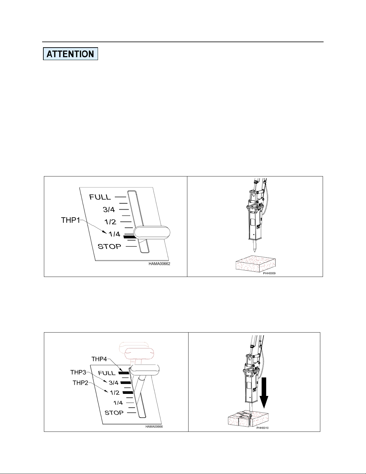
2. At idle (THP1), raise the hammer off the ground. Place the hammer vertical and
activate the hammer hydraulic circuit for 3 – 5 second intervals. Continue for an
additional 3 – 4 times to ensure that all the air has been purged from the hoses and
the hammer before first use. Failure to do this could result in damage to the
hammer’s internal components.
3. Place the hammer firmly against the material to be broken (see “PRELOAD
THE TOOL BEFORE STARTING”). Operate the hammer in a vertical position for
approximately 10 minutes at one-half (THP2) engine speed. Increase the engine
speed to three-quarters (THP3) and continue operating at this speed for another 10
to 20 minutes. Increase to full engine speed (THP4). Maintain vertical position for
the duration of the operation.
- 28 -
Page 30
START-UP OPERATION
BEFORE STARTING THE HAMMER
PRE-OPERATION INSPECTION AND WARM UP
Before operating the NPK HYDRAULIC HAMMER, be sure to perform the specified
inspection, see “ROUTINE INSPECTION AND MAINTENANCE”.
Warm up the NPK HYDRAULIC HAMMER, see below, and the base machine in
accordance with the machine manufacturer’s instruction manual. This is especially
important during cold weather operation.
DAILY START-UP PROCEDURE
Operate the NPK HYDRAULIC HAMMER in the vertical position, at 3/4 engine throttle
setting, for about 1-2 minutes. During this period, inspect the NPK HYDRAULIC
HAMMER and INSTALLATION KIT for leaks or loose connections.
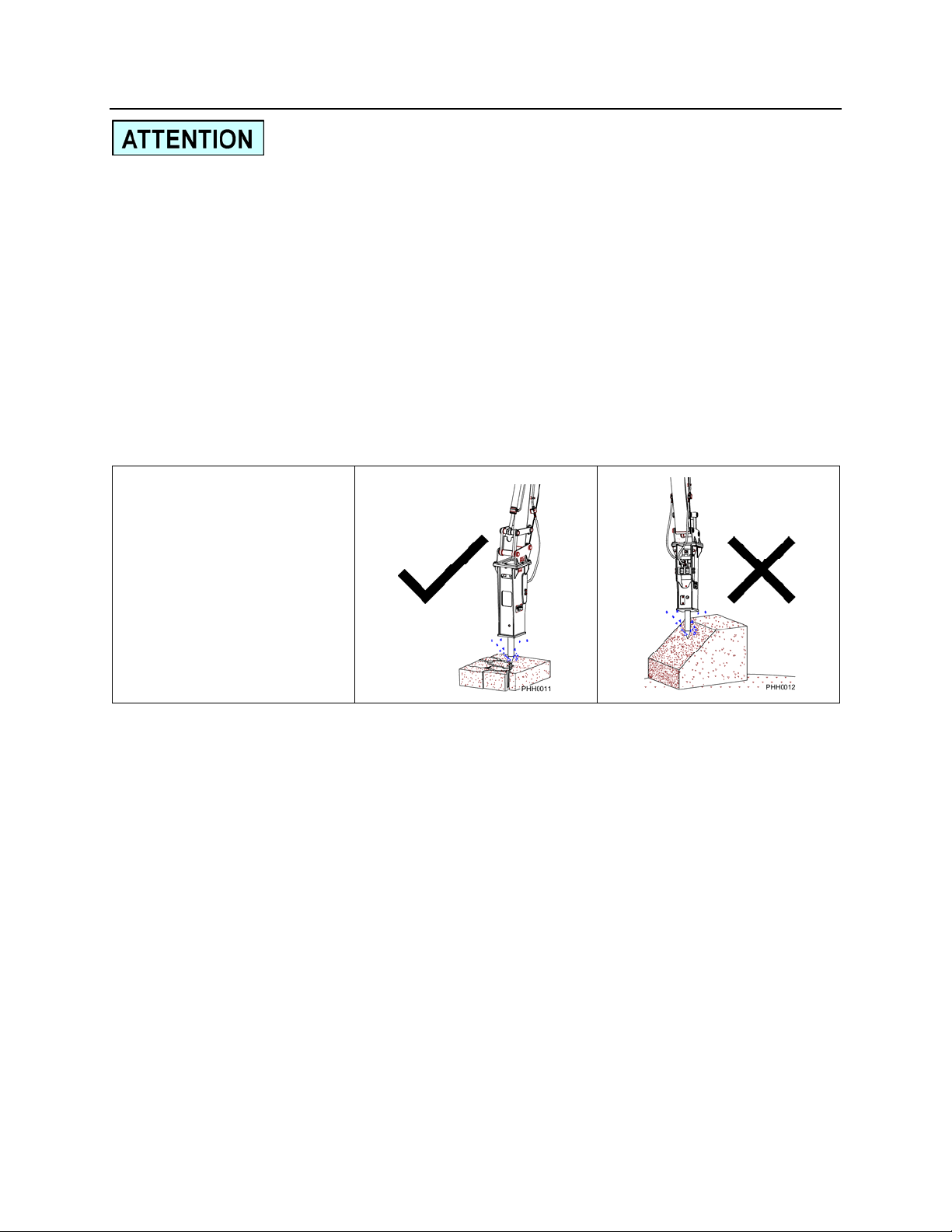
Do not operate on a
slanted surface during
the start-up operation.
- 29 -
Page 31
OPERATION
SAFE OPERATING INSTRUCTIONS
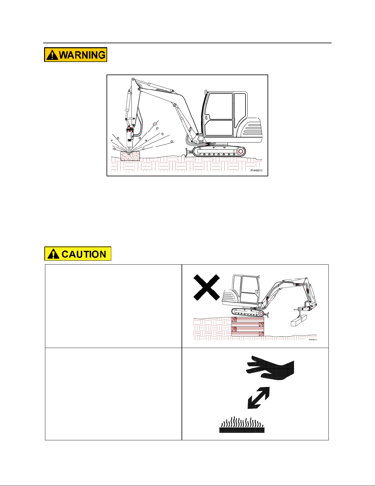
DO NOT OPERATE THE HAMMER WITHOUT AN IMPACT RESISTANT
CAB WINDOW OR SHIELD IN PLACE!
BEWARE OF FLYING DEBRIS FROM THE HAMMER TOOL POINT!
An impact resistant cab window or shield must be in place to protect the operator.
Do not use the hammer in a way as to cause rock, etc. to be thrown towards the cab.
DO NOT USE THE HAMMER AS
A HOIST
The hammer is not intended to lift an
object. To do so, can be dangerous!
DO NOT TOUCH HOT TOOL
AFTER USING
!
- 30 -
Page 32
OPERATION
OPERATING TECHNIQUES & PRECAUTIONS
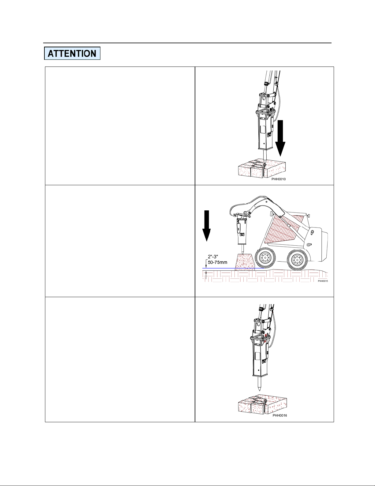
PRELOAD THE TOOL BEFORE
STARTING
Press the tip of the demolition tool vertically
against the object to be broken. Be sure
the object is stable before activating the
NPK HYDRAULIC HAMMER.
APPLY DOWNFORCE ON THE
TOOL
Raise the front of the machine slightly by
applying down force on the demolition tool.
Press the control lever or the foot pedal to
start the NPK HYDRAULIC HAMMER.
Applying excessive force to the hammer
will raise the carrier too high and jolt the
operator when the material breaks. Let
the NPK HYDRAULIC HAMMER do the
work.
AVOID BLANK HAMMERING
As soon as the material is broken, release
the control lever or pedal to prevent
unnecessary blank hammering.
Blank hammering is continued hammer
operation after the material is broken.
This will overheat the hydraulic system,
and cause undue wear of hammer parts,
and result in eventual tool retaining pin
failures, see page 54.
- 31 -
Page 33
OPERATION
OPERATING TECHNIQUES & PRECAUTIONS
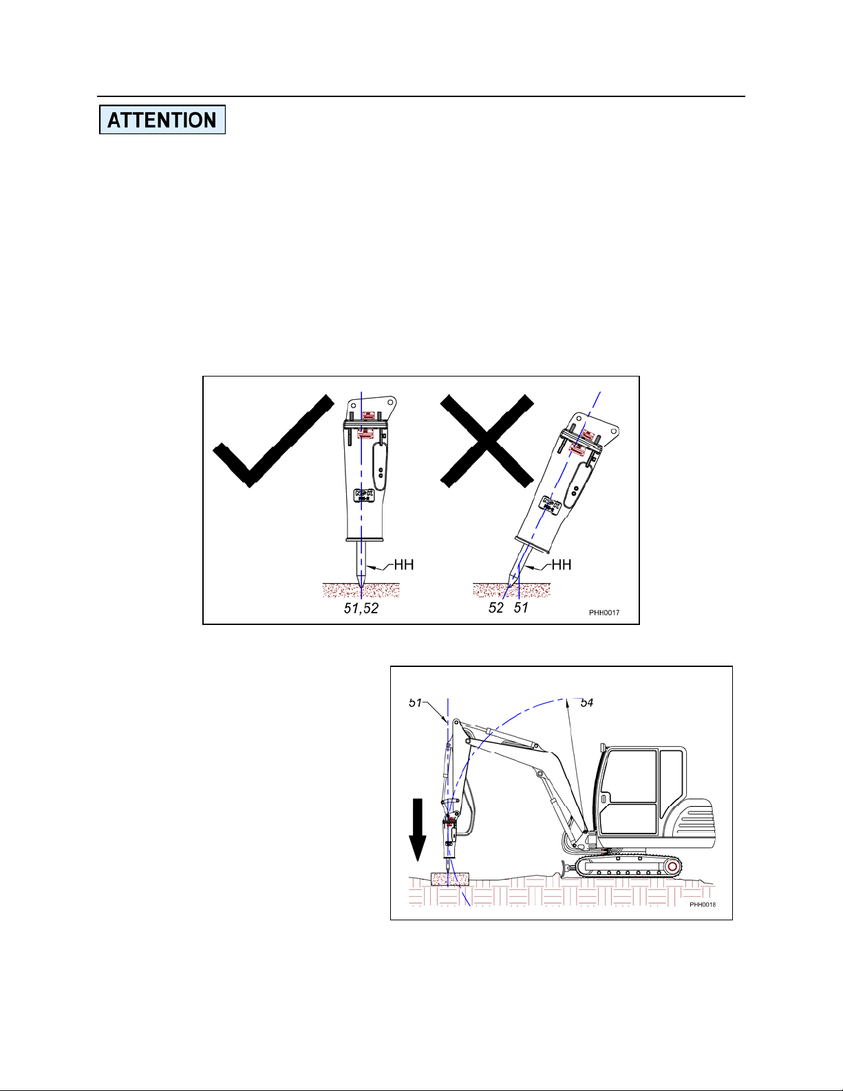
DO NOT SLANT HAMMER
For the most efficient demolition, align the direction of force (51) from the boom with the
penetration direction (52) of the tool (HH). Failure to do this decreases the transfer of
energy from the piston to the rock and increases the bending forces at the fulcrum of
the tool. This unnecessary added stress leads to the following problems:
1. Premature wearing of the tool bushings and/or tool breakage.
2. Breakage of tie rods.
3. Breakage of bracket bolts.
When the tool is working at the incorrect angle, it will bind causing the sound of the
hammer to change.
Keep the boom direction of force (51)
in the same direction the tool is
penetrating. Use the boom cylinder
to preload the hammer (apply down
force), and use the bucket and stick
cylinders for alignment. Keep the tool
tangent to the arc of the boom (54).
- 32 -
Page 34
OPERATION
OPERATING TECHNIQUES & PRECAUTIONS
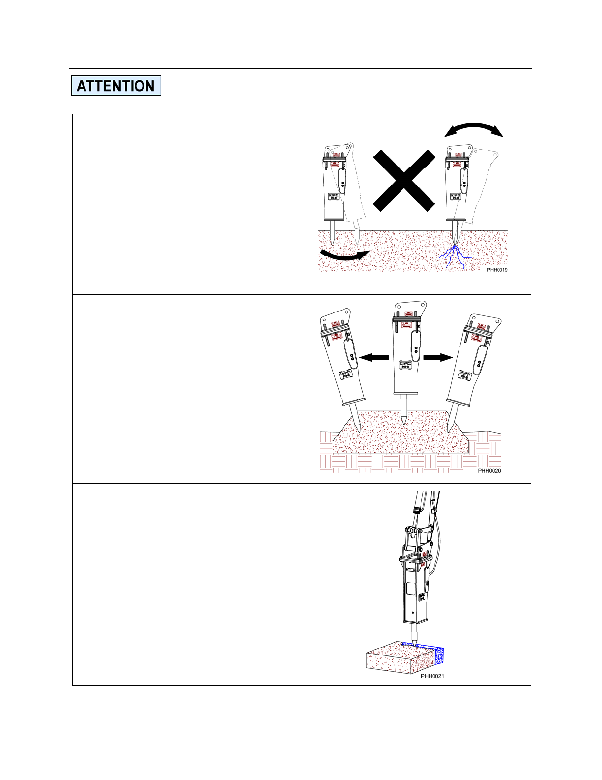
DO NOT USE THE HAMMER
TOOL AS A PRY BAR
Excessive prying can cause premature
bushing wear and tool or tie rod
breakage. When hammering materials
that allow the tool to penetrate before
breaking, move the hammer slightly
fore and aft to create a cone-shaped
hole. The vented hole allows trapped
dust and heat to escape, increases the
tool penetration rate into the material,
and prevents overheating the tool tip.
DO NOT HAMMER CONTINU-
OUSLY IN THE SAME
POSITION FOR MORE THAN 30
SECONDS
If the tool cannot break or penetrate
into the material after hammering in the
same position for 30 seconds, change
the working location. Hammering in the
same position for a long time will
reduce the working efficiency, increase
the hydraulic oil temperature, overheat
the tool tip and accelerate tool wear.
ALWAYS WORK BY BREAKING
TO A FREE FACE
The material must have somewhere to
break. Start at an edge.
- 33 -
Page 35
OPERATION
OPERATING TECHNIQUES & PRECAUTIONS
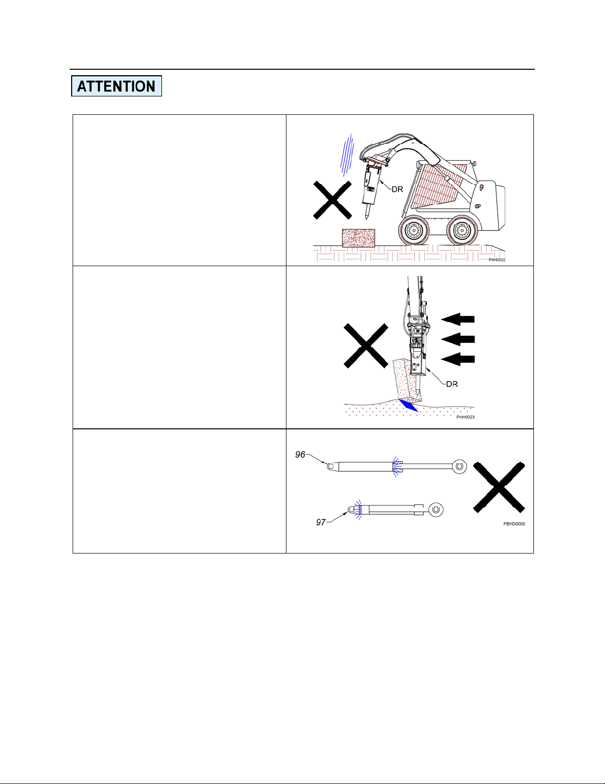
DO NOT DROP THE HAMMER
RAPIDLY ON AN OBJECT
Remember, the hammer assembly
(DR) is heavier than an empty bucket
and will move faster than expected.
DO NOT USE THE HAMMER
ASSEMBLY (DR) TO MOVE
LARGE OBJECTS
Do not use the hammer assembly
(DR) for purposes other than for what
it was intended.
AVOID OPERATING THE
HAMMER WITH CYLINDERS
AT THE END OF STROKE
Continuous operation with the
cylinders fully closed (97) or extended
(96) may damage the hydraulic
cylinders.
- 34 -
Page 36
OPERATION
OPERATING TECHNIQUES & PRECAUTIONS
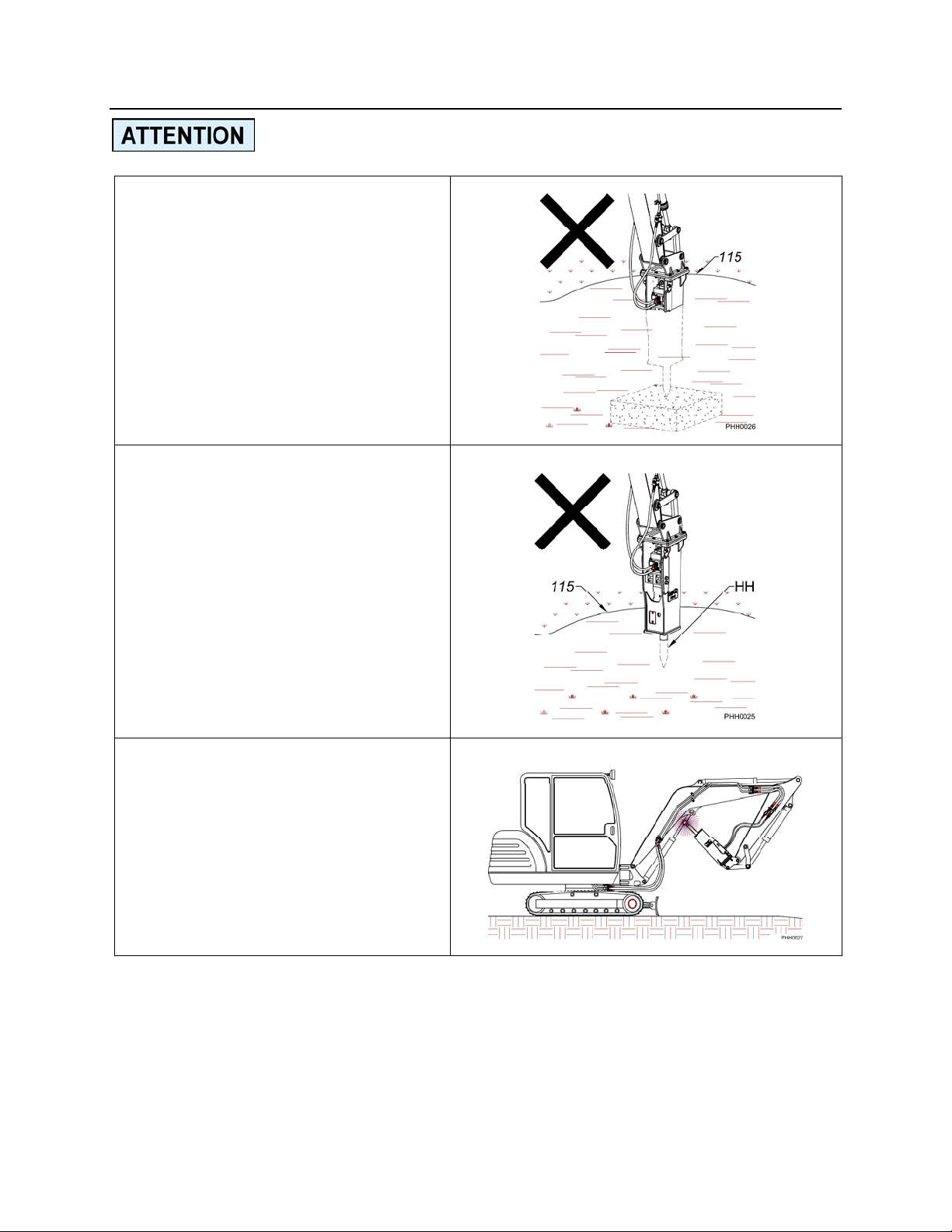
DO NOT OPERATE HAMMER
UNDERWATER
Do not allow parts, other than the
tool, to go below water level (115).
Underwater operation will damage
the hammer and allow water to enter
the carrier’s hydraulic system. The
hammer can be modified for
underwater use – contact your NPK
dealer for more information.
DO NOT SUBMERGE A HOT
TOOL IN WATER
The tip of the tool (HH) may be hot
from operation. Submerging below
water level (115) can cause the tip of
the tool to become brittle and break
prematurely.
!
DO NOT ALLOW THE
HAMMER TOOL TO HIT THE
BOTTOM OF THE BOOM
ASSEMBLY
Use caution when tucking the hammer
in tight to the boom assembly for
transportation.
- 35 -
Page 37
IMPACT ENERGY TRANSMISSION THROUGH
TOOLS
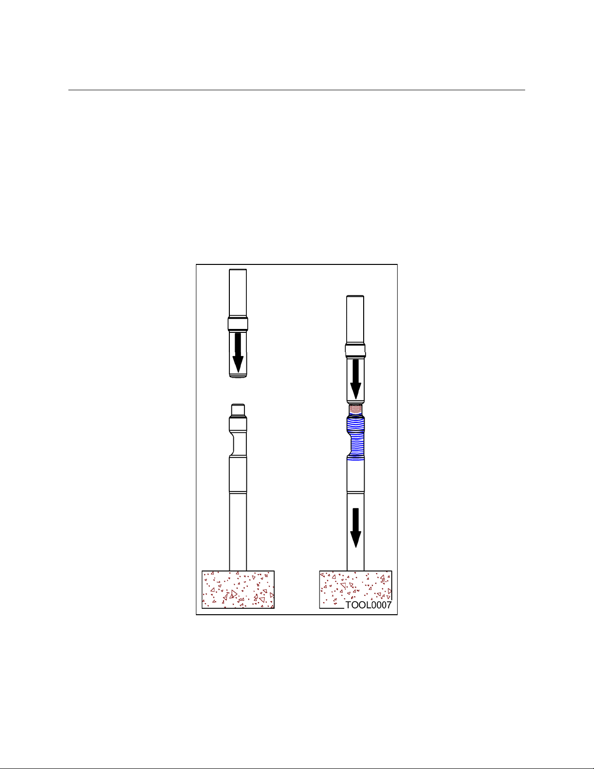
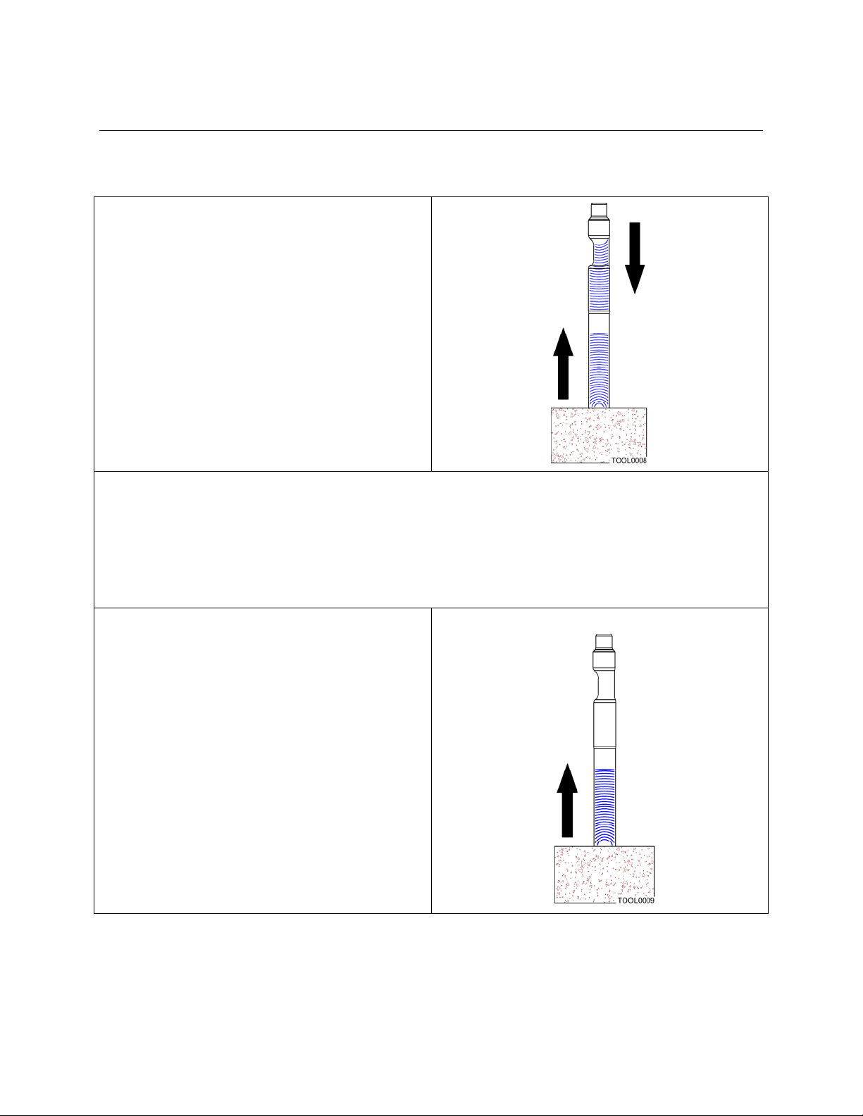
A hydraulic hammer converts hydraulic power to kinetic energy. The kinetic energy is
delivered by the hammer piston to the tool as an impact force.
Unlike a slowly transmitted force, such as the force with which a hydraulic cylinder
extends, the impact force produced by the piston when it hits the tool is transmitted
through the interior of the tool as a compression stress wave until it reaches the rock,
concrete, or other material that the tool is about to break. The compression wave speed
is equal to the speed of sound through steel, i.e., approximately 15,000 ft/sec.
Therefore, if the tool is three feet long, the impact force reaches the object to be broken
1/5000 (0.0002) second after the piston hits the tool.
Impact force is transmitted as stress waves through the tool.
- 36 -
Page 38
IMPACT ENERGY TRANSMISSION THROUGH
TOOLS
IMPACT STRESS WAVES AT THE END OF THE TOOL
When the tool is in contact with the
material to be broken, most of the
compression stress waves are transferred
to the material, and the energy of the
compression waves then breaks the
material. However, not all the energy of
the compression waves is transmitted to
the material to be broken, part of it is
reconverted into reverse compression, or
tensile, waves that then travel back
through the tool.
When the tool is not in contact with the material to be broken, the energy of the
compression waves has nowhere to go and therefore, returns totally in the chisel as
tensile waves. This is referred to as a “blank hammer blow”, see page 31.
The compression waves and the tensile
waves travel in a complex manner in the
tool during hammer operation. While
these waves are gradually being
attenuated by the internal friction of the
tool and by the friction between the tool
and the tool holder bushings, the next
impact strikes the tool. Excessively heavy
contact between the tool and tool bushings
causes uneven stress concentrations.
This leads to premature tool failure, as
seen in later sections of this manual.
- 37 -
Page 39
TOOL BREAKAGE
The following is a description of tool failures, causes of tool failures, preventative
measures, and application of warranty.
TOOL BREAKAGE DUE TO EXCESSIVE BENDING MOMENT
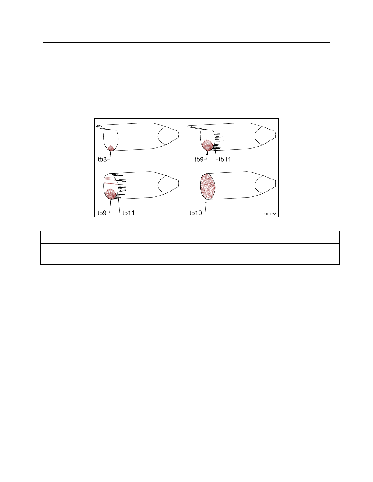
If the tool is subjected to excessive bending moment caused by slant hammering or
prying, the tool will break. Tool breaks will generally resemble one of the following
examples:
tb8. Starting point of crack that leads to breakage. tb9. Starting point of break.
tb10. Sudden break from instant overload condition,
tb11. Galling
(face will look very dull gray).
CHARACTERISTICS OF THE BROKEN SECTION
1. The starting point of a fatigue fracture is on the surface of the tool and located at the
front or rear side of the tool, with the hammer installed on the excavator and viewed
from the cab.
2. The tool has galled areas on its surface. The galling initiates a surface crack from
which the fatigue fracture starts. The stress cracks, combined with bending loads
and impact shock, can break the tool.
PREVENTATIVE MEASURES
1. Properly position the hammer so as not to develop a bending moment in the tool.
2. Apply sufficient grease to prevent the tool from developing cracks due to galling.
This will also assure longer tool bushing life.
WARRANTY
NPK Warranty does not apply to this type of failure.
- 38 -
Page 40
TOOL BREAKAGE
TOOL BREAKAGE DUE TO EXCESSIVE WEAR OF THE TOOL
HOLDER BUSHINGS
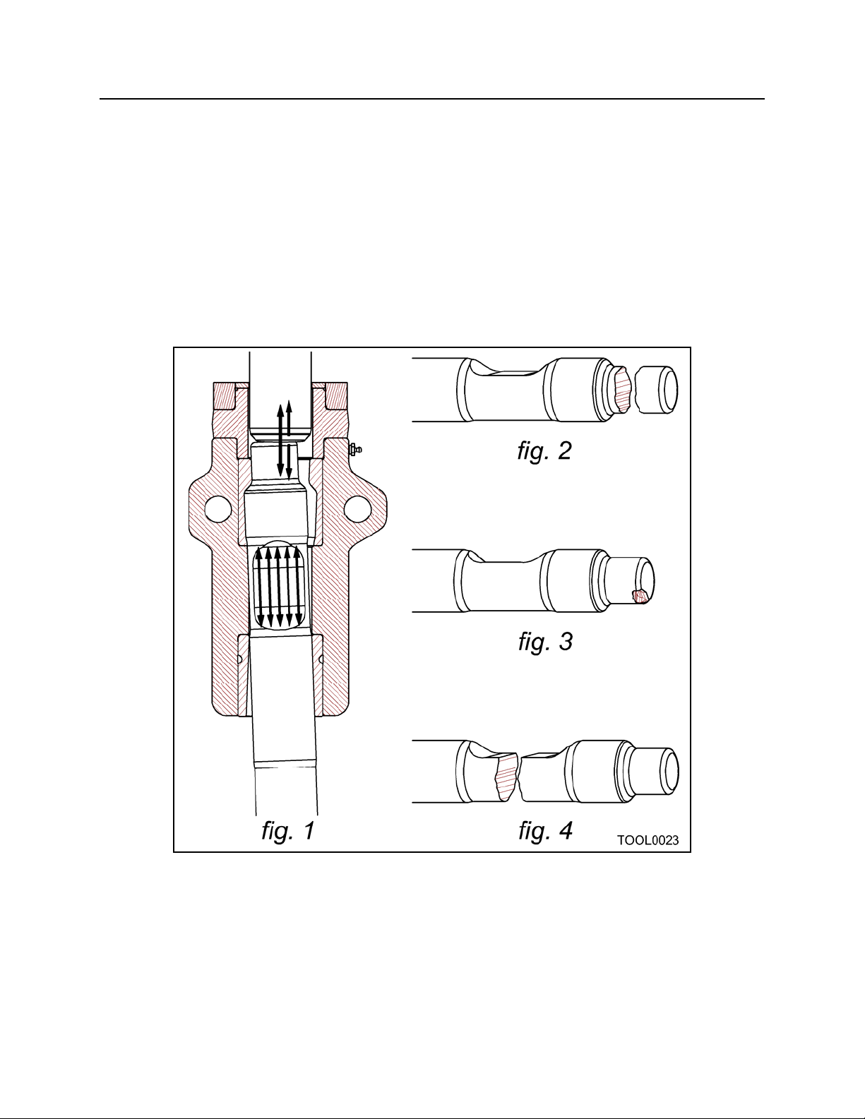
If the hydraulic hammer is used with tool holder bushings worn beyond specifications,
the tool will be at an excessive angle to the piston at the moment of impact. The entire
force of the piston is concentrated in a small area of the impact head of the tool (Fig. 1).
This results in the impact head being chipped or broken (Fig. 2 & 3). With the tool at an
angle, and in excessive side loading contact with the tool holder bushings, the shock
load traveling down the tool is unevenly concentrated (Fig. 1). This can result in the tool
breaking through the retaining pin slot (Fig. 4).
- 39 -
Page 41
TOOL BREAKAGE
TOOL BREAKAGE DUE TO EXCESSIVE WEAR OF THE TOOL
HOLDER BUSHINGS
PREVENTATIVE MEASURES
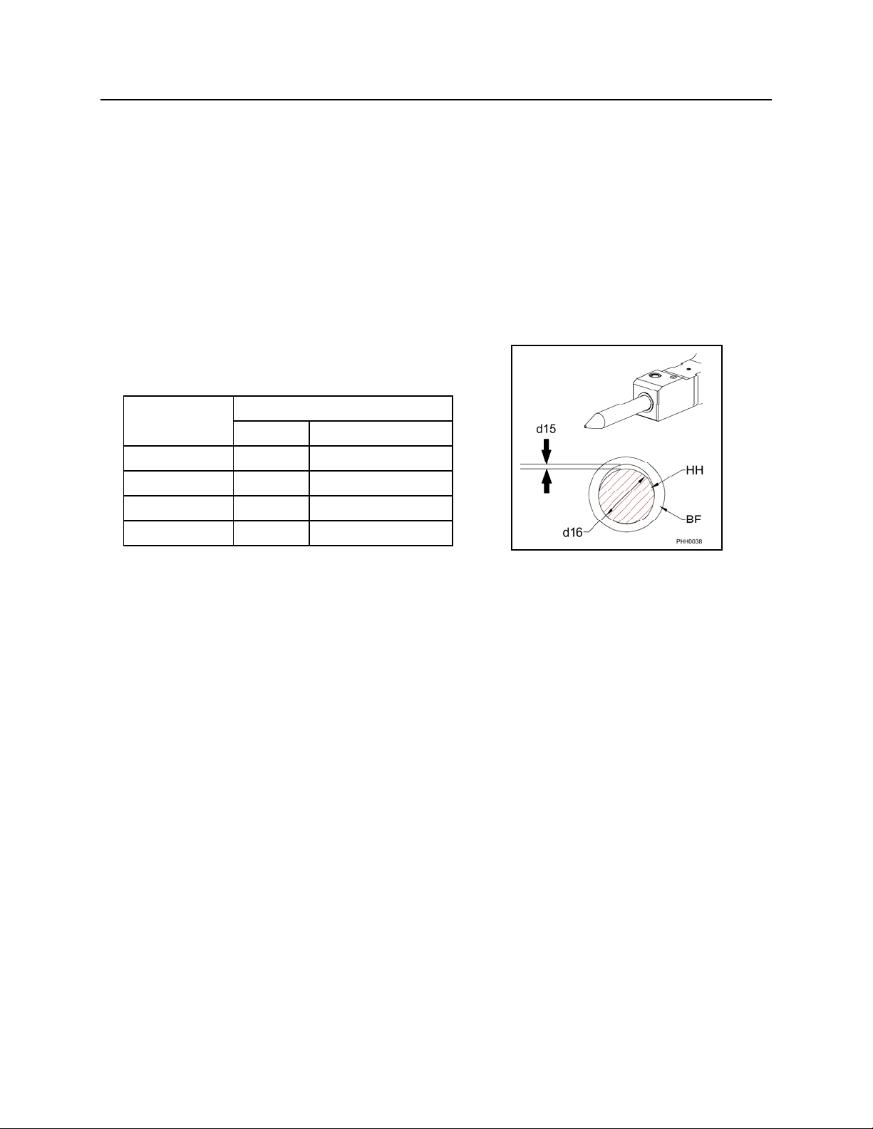
Replace the tool bushing (BF), and/or tool (HH), when the tool to bushing gap (d15)
reaches the maximum clearance. To determine whether the bushing or tool requires
replacement, follow the instructions in the “MAXIMUM TOOL TO TOOL BUSHING
CLEARANCE” section of this manual.
HAMMER MAXIMUM CLEARANCE
MODEL in (mm)
PH1
PH2
PH3
PH4
WARRANTY
NPK Warranty does not cover tool failure caused by worn tool holder bushings.
1/4
1/4
1/4
1/4
6
6
6
6
BF. Tool Bushing
HH. Tool
d15. Clearance
d16. Tool Diameter
- 40 -
Page 42
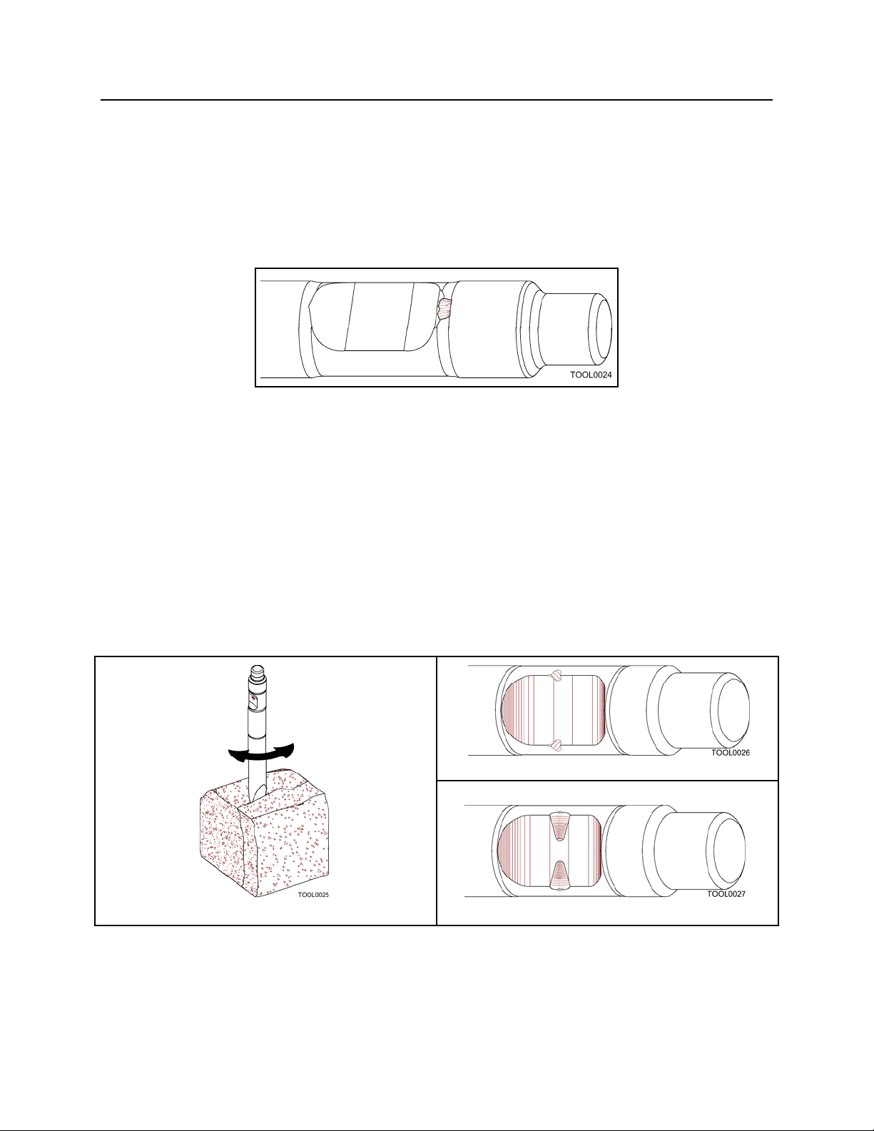
TOOL BREAKAGE
A. CHIPPING IN RETAINING PIN SLOT
The tool may become chipped at the upper end of the retaining pin slot where it
contacts the retaining pin. Free standing oversize rock may sometimes be broken with
only a few hammer blows. If the operator does not stop hammering immediately, the
tool will hit the retaining pin (blank hammering), and can chip the upper end of the
retaining pin slot.
PREVENTATIVE MEASURES
When the material is broken, stop operating the hammer immediately. Periodically
check the tool and grind smooth any chipped areas to prevent stress cracks.
B. DEFORMATION OF THE RETAINING PIN SLOT SIDES
The tool may become chipped or deformed in the area where it is in contact with the
retaining pin. As the tool breaks material, it will try to follow any fracture lines in the
material (Fig. 1). This causes a chisel point tool to twist in the tool holder. The retaining
pin limits how far the tool can twist. If this happens often enough, the pin contact area
of the tool can become chipped (Fig. 2) or deformed (Fig. 3).
Fig. 2
Fig. 1
Fig. 3
PREVENTATIVE MEASURES
The operator should place the chisel point in line with fractures or laminations in the
material, not at an angle. The tool should be checked periodically for chipped areas.
Grind smooth any chipped areas to prevent stress cracks in the tool.
- 41 -
Page 43
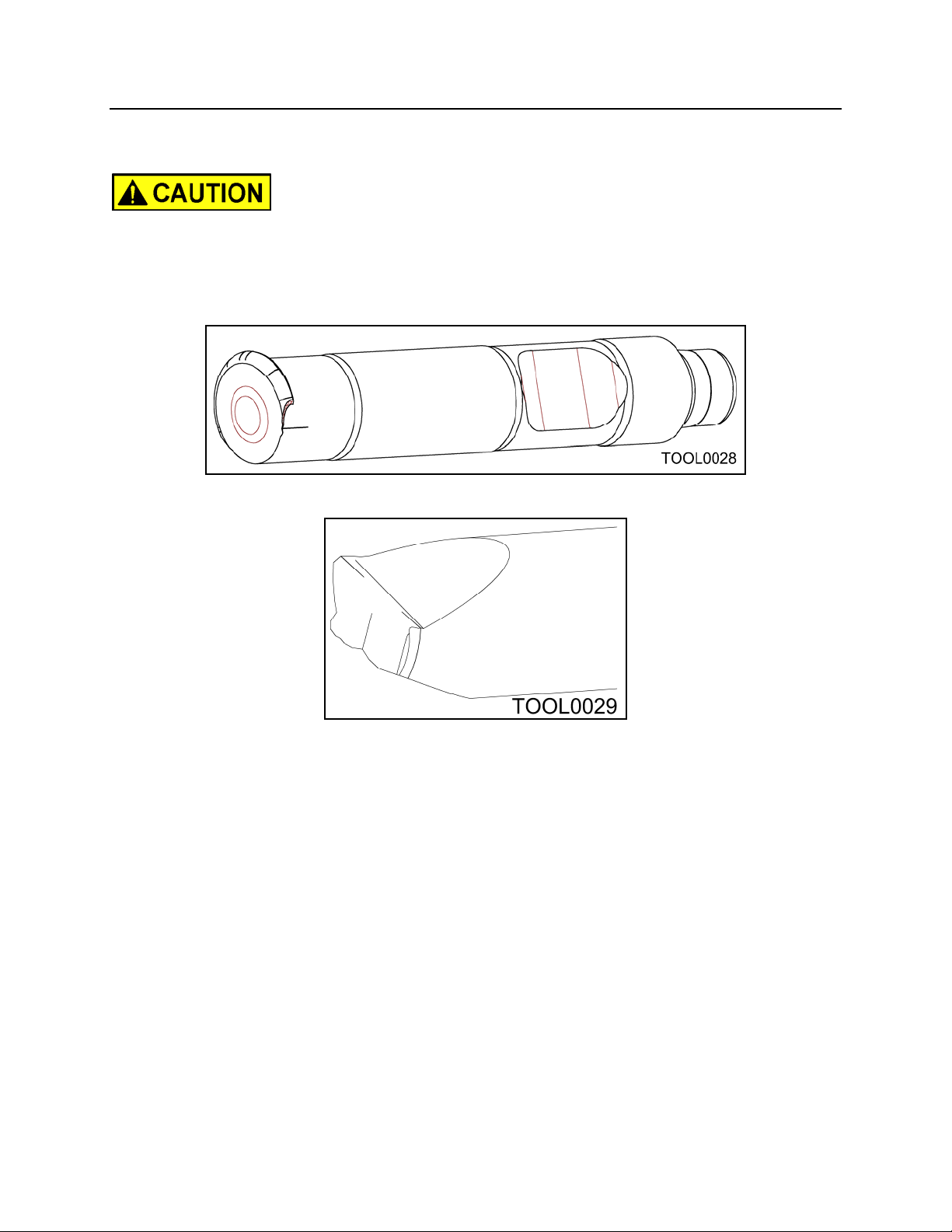
TOOL BREAKAGE
C. DEFORMATION OF THE TOOL TIP
Hammering continuously in one position for over 30 seconds will overheat the tool tip. If
this is done repeatedly, the tip will lose temper and mushroom. Overheating wears the
tip faster and can allow the tip to chip.
PREVENTATIVE MEASURES
Move tool position if material is not broken after 30 seconds of hammering. If the
material still resists breaking, a larger hammer may be required.
- 42 -
Page 44
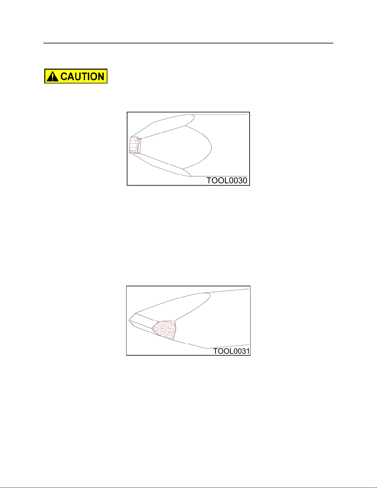
TOOL BREAKAGE
D. CHIPPING OF A MOIL POINT TOOL TIP
Moil (“P”) tools are intended for use on concrete or soft rock. The use of moil tools on
hard rock may result in the point being chipped.
PREVENTATIVE MEASURES
Use a chisel point (“FX” or “FY”) tool or a larger size hammer.
E. CHIPPING OF A CHISEL TOOL TIP
Chisel tool tips may be chipped due to hammer being undersize for application.
Overheating tool by hammering for more than 30 seconds in one spot can cause
chipping.
PREVENTATIVE MEASURES
Use correct size hammer for job conditions. Do not hammer for more than 30 seconds
without moving hammer.
WARRANTY
NPK Warranty does not cover types A, B, C, D and E problems.
- 43 -
Page 45
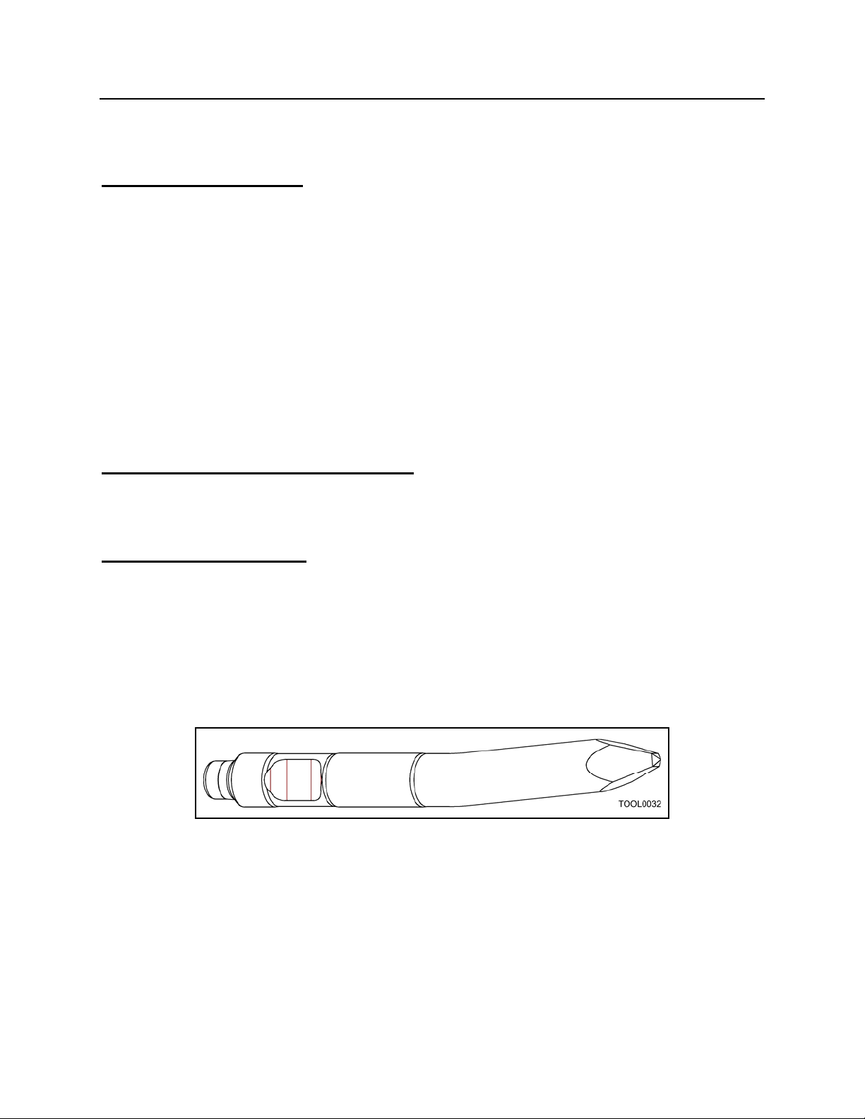
TOOL BREAKAGE
TEMPERATURE RELATED TOOL PROBLEMS
LOW TEMPERATURE
Metallic material becomes brittle in a low temperature environment and particularly
sensitive to impact stress.
PREVENTATIVE MEASURES
Warm the tool before starting to operate the hammer when temperature is below 32°F,
(0°C).
WARRANTY
NPK Warranty does not cover this type of failure.
EXCESSIVE SLANT HAMMERING
When constant slant hammering is performed while using boom downforce, the tool
may become deformed as shown in the picture below.
HIGH TEMPERATURE
When the tool is used in a high temperature environment, such as for slag removal from
a furnace, the tool may be deformed as shown in the picture below.
PREVENTATIVE MEASURES
Use compressed air to keep the tool cool enough not to deform.
WARRANTY
NPK Warranty does not cover this type of failure.
- 44 -
Page 46
TOOL BREAKAGE
TOOL BREAKAGE DUE TO CORROSION
Corrosion on the tool surface causes stress concentrations in the corroded area and a
fatigue fracture can occur. These fractures, combined with impact stress, can lead to
tool breakage.
PREVENTATIVE MEASURES
After using the tool in salt water, or exposing it to a corrosive environment, or before
long term storage, be sure to rinse with fresh water. Dry the tool and coat it with grease
to protect it from corrosion.
WARRANTY
NPK Warranty does not cover this type of failure.
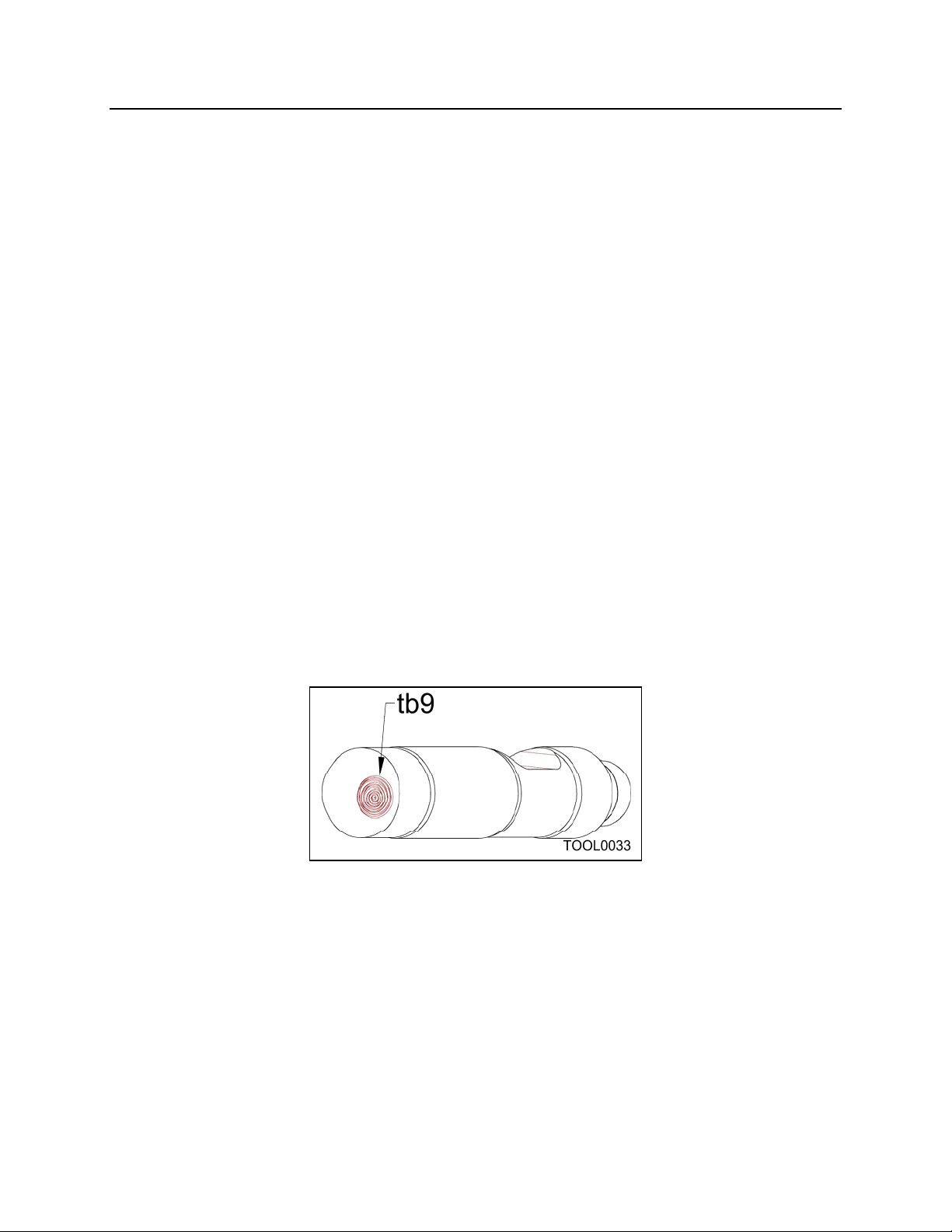
TOOL BREAKAGE DUE TO DEFECTIVE MATERIAL
If metal fatigue originates from the interior, not the exterior, the material has some
defect and fatigue will break the tool. The picture below illustrates the broken section.
The starting point of breakage (tb9) is inside the tool, not on the surface.
WARRANTY
NPK Warranty does cover this type of failure.
- 45 -
Page 47
ROUTINE INSPECTION AND MAINTENANCE
1. VISUAL INSPECTION
Detect a potential problem early.
FASTENERS
Inspect all fasteners and retighten as necessary. See page 58 for torque values.
WELDS
Check for cracks, repair as necessary, see the PH Service Manual.
HOSES AND TUBING
Check for oil leaks, loose clamps and hose abrasion.
RUBBER MOUNTS
Inspect for damage.
HYDRAULIC OIL: MAINTAIN A CLEAN HYDRAULIC SYSTEM
If non-petroleum oil is used, contact the NPK Service Department for compatibility.
Keep hoses clean and capped when dismounting or storing hammer. Change oil and
filters as recommended by carrier manufacturer. Periodic oil sampling is recommended.
2. DEMOLITION TOOL LUBRICATION
Important:
It is imperative that grease is maintained in the tool bushing
contact area at all times. This may require hourly greasing
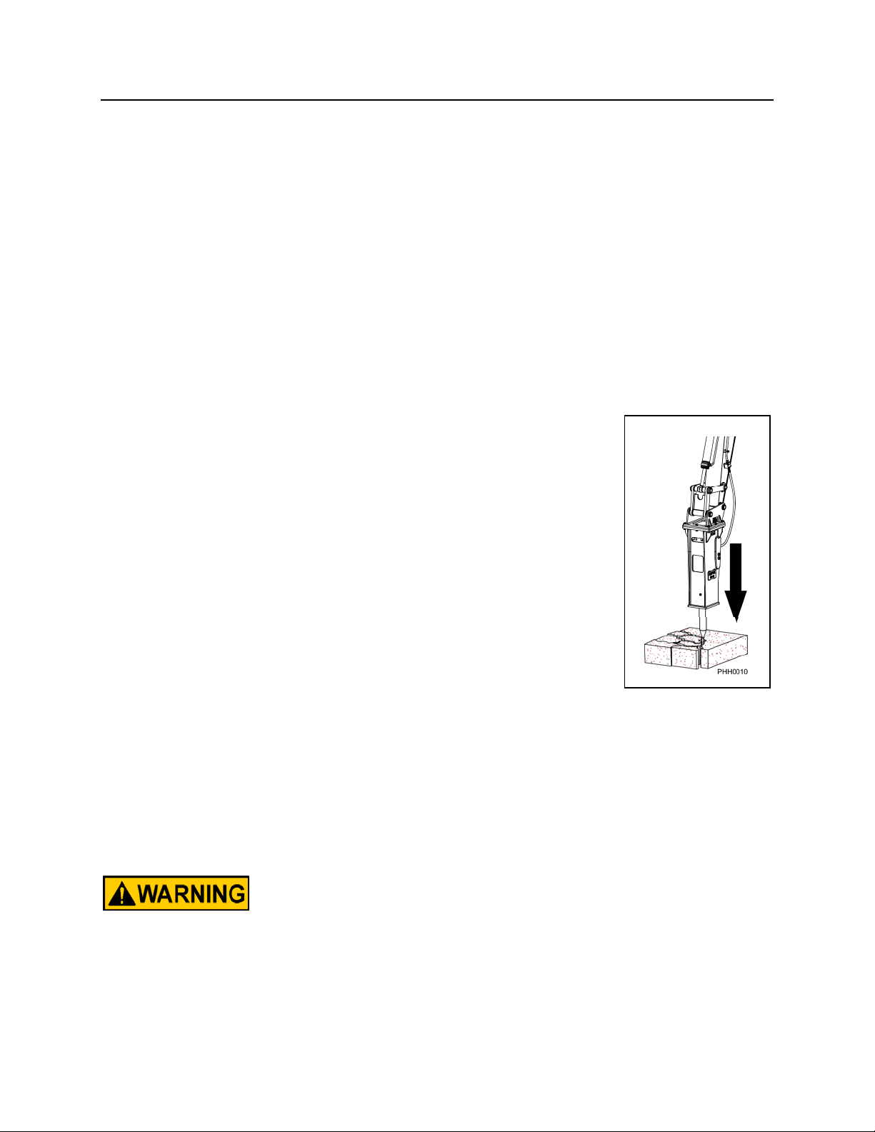
depending on job conditions.
Important:
The hammer must be in a vertical position with downforce applied
to push the tool all the way in. This prevents grease from entering
piston impact area. Pump grease into grease fitting until
grease is seen coming out between the tool and bushing.
USE A GOOD QUALITY, HIGH TEMPERATURE EP#2 GREASE
CONTAINING ANTI-WEAR ADDITIVES. NPK recommends a
Lithium Base, Moly (Molybdenum Disulfide) or other surface
protecting additives, EP (Extreme Pressure), NLGI #2 Grease.
A high drop point (350° to 500°) grease is desirable.
If machine is equipped with an AUTO LUBE System, check grease reservoir daily.
3. TOOL and TOOL BUSHING WEAR
Check the tool and tool bushings for damage, wear or deformation on a regular weekly
basis. Replace the tool and/or bushings when wear exceeds the maximum clearance
limit. See MAXIMUM TOOL TO TOOL BUSHING CLEARANCE, see pages 52 and 53.
Do not hardface or sharpen the tool point with a cutting torch. Excessive
heat from torching or welding causes embrittlement, breakage, and
flying pieces. Resharpen only with a lathe or milling machine using
sufficient cooling. Please consult your authorized NPK Dealer or NPK
Service Department for additional information.
4. DO NOT SUBMERGE HAMMER UNDERWATER
Unless modified for underwater operation.
- 46 -
Page 48

WEEKLY INSPECTION
1. WELDS
Check for cracks, repair as necessary. Consult your authorized NPK Dealer or
NPK Service Department for additional information.
2. TOOL RETAINING PIN
Remove the retaining pin and inspect for peening caused by excessive blank
hammering. If necessary, grind edges smooth as shown in TOOL RETAINING PIN
INSPECTION, see page 57. The retaining pin must rotate freely.
3. DEMOLITION TOOL
Remove the demolition tool and inspect for peening caused by excessive blank
hammering. If necessary, grind edges smooth as shown in TOOL INSPECTION,
see page 54.
4. GAS CHARGE
Check and adjust, if required, see pages 59 through 64.
- 47 -
Page 49
TOOLS
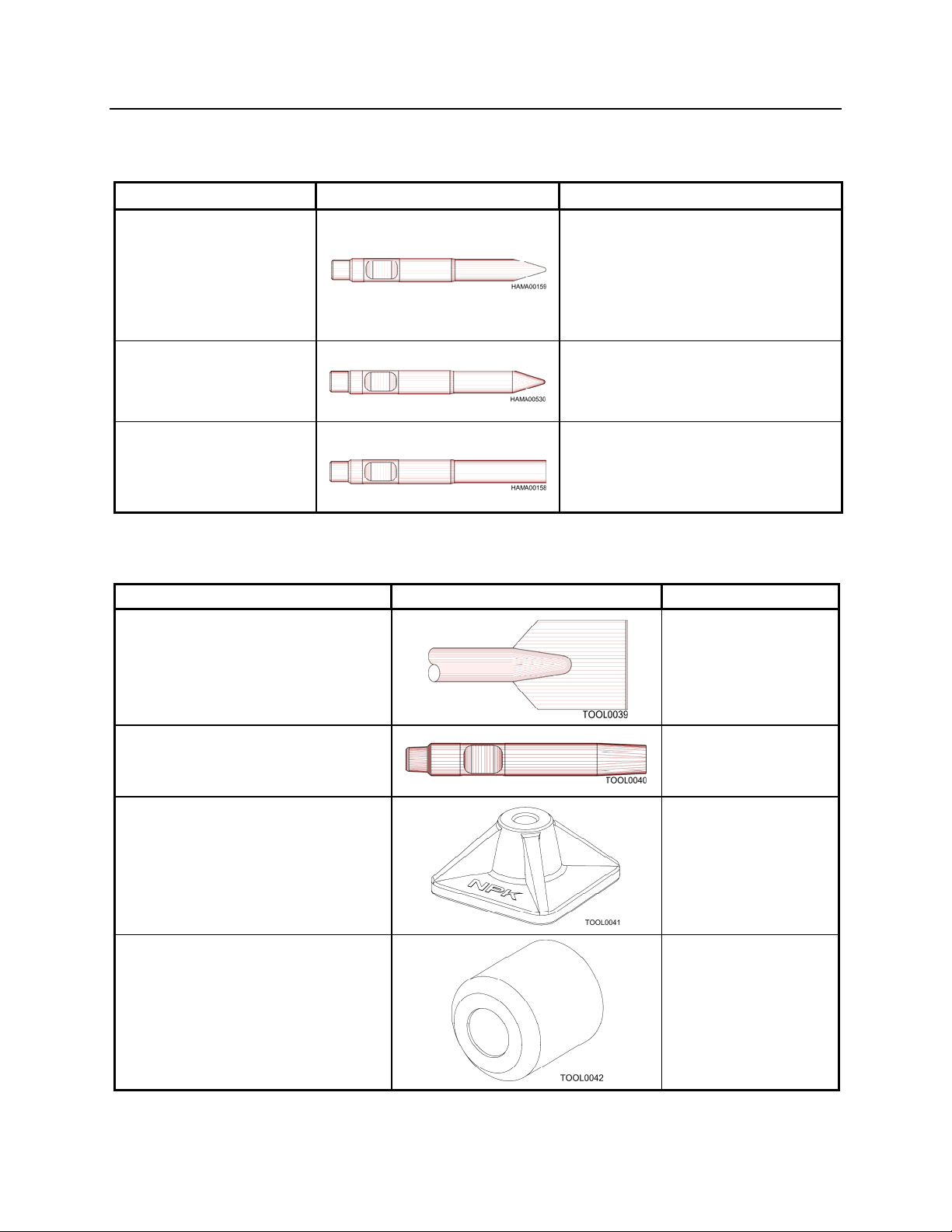
STANDARD TOOLS
DEMOLITION TOOL SHAPE APPLICATIONS
CHISEL (FX)
The cross cut (FX) tool
cuts at right angle, or
crosswise, to the stick and
boom of the excavator.
MOIL (P)
BLUNT (E)
Trenching
Cutting casting gates
Breaking oversize
General demolition
Concrete breaking
Highway construction
General demolition
Secondary breaking
Breaking oversize
Slag removal
ACCESSORY TOOLS
SPECIALTY TOOL SHAPE APPLICATIONS
FROST CUTTER
Cross cut (SX), In Line (SY)
for PH1 – PH4
ADAPTER TOOL
for PH1 – PH4
TAMPER PLATE
(use with adapter tool)
12” x 12” for PH1 – PH2
16” x 16” for PH3 – PH4
POST and PIPE DRIVER
(use with adapter tool)
for PH1 – PH4
Edge of trenching
Frost cutting
For attachments
listed below
Soil compaction
Driving sheeting
Driving guard rails
Driving fence posts
- 48 -
Page 50
TOOLS
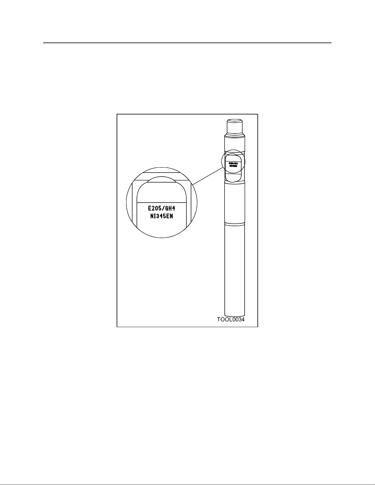
TOOL IDENTIFICATION
NPK demolition tools can be identified by the numbers found stamped in the retaining
pin slot area. These numbers must be included in all warranty correspondences
regarding a broken tool. Photos must also be included.
- 49 -
Page 51
TOOLS
CHANGING THE TOOL
TOOL REMOVAL
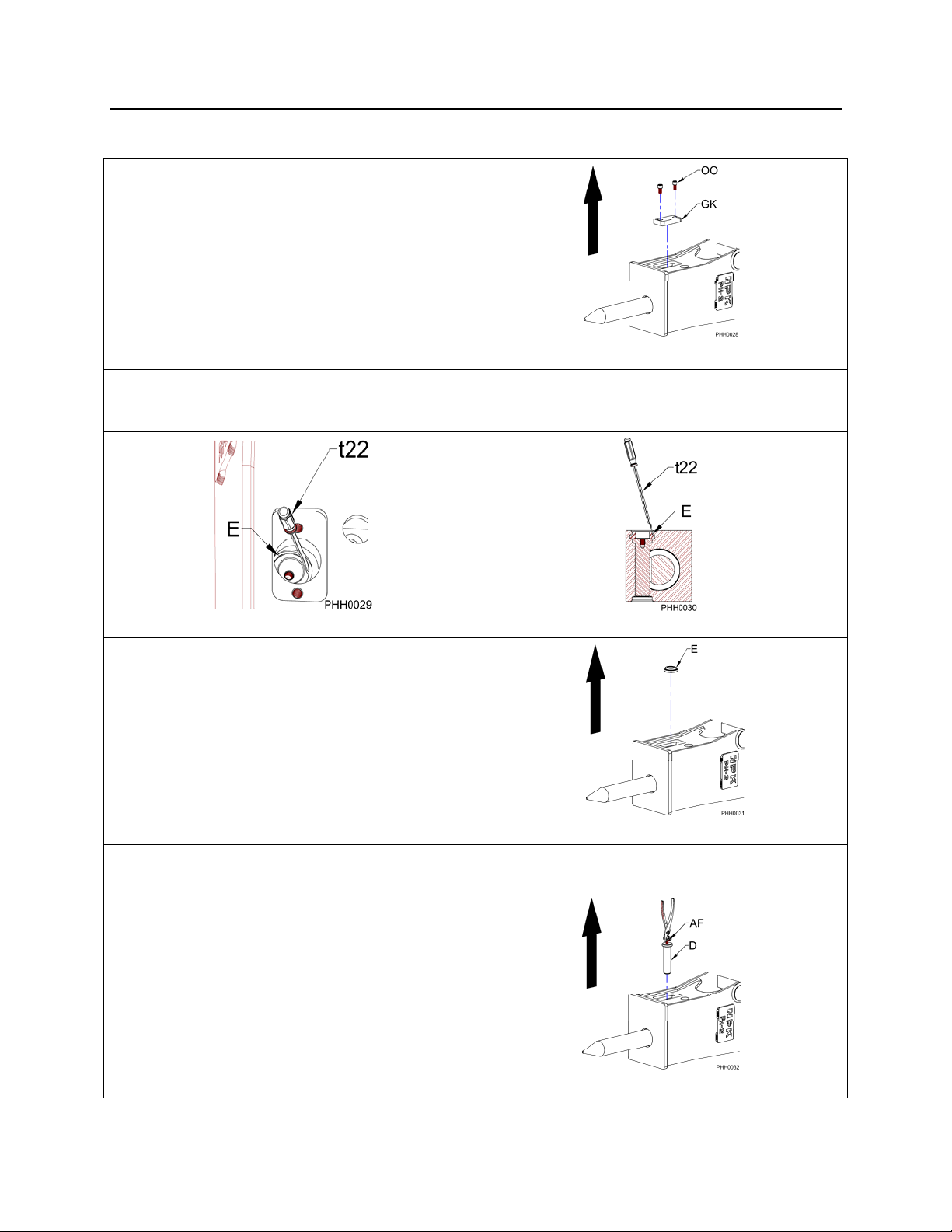
1. Remove the two socket head cap
screws (OO) that attach the retaining
pin stopper plate (GK) to the hammer
bracket. Remove the retaining pin
stopper plate.
Figure 1
2. Remove the retaining pin ring (E) by using a screwdriver (t22), see Figures 2 and 3.
It will easily come out if pried at an angle as shown in Figure 3.
Figure 2
3. Remove the retaining pin ring (E).
4. Screw a 6mm hex head bolt (AF) or cap screw into the retaining pin (D).
5. Pull the retaining pin out. If the
retaining pin is jammed, use a hammer
and drift pin to drive it out from the
opposite side.
Figure 3
Figure 4
Figure 5
- 50 -
Page 52
TOOLS
CHANGING THE TOOL
TOOL REMOVAL
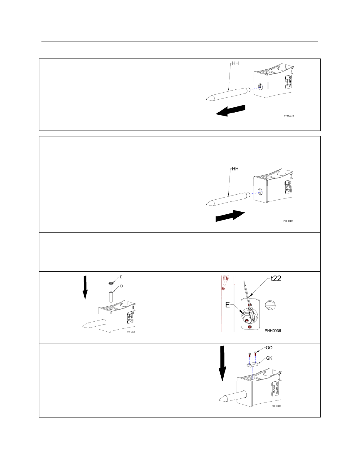
6. Remove the tool (HH).
TOOL INSTALLATION
1. Clean the retaining pin bore.
2. Coat the surface of the tool (HH) with
grease, then install.
Figure 6
Figure 7
3. Coat the retaining pin (D) with grease, then install.
4. Install the retaining pin ring (E) by using the handle of a screwdriver (t22) as shown
in Figure 9.
Figure 8
Figure 9
5. Install the retaining pin stopper plate
(GK). Torque bolts (OO) to 85 ft. lbs.
(115 Nm).
Figure 10
- 51 -
Page 53
TOOLS
MAXIMUM TOOL TO TOOL BUSHING CLEARANCE
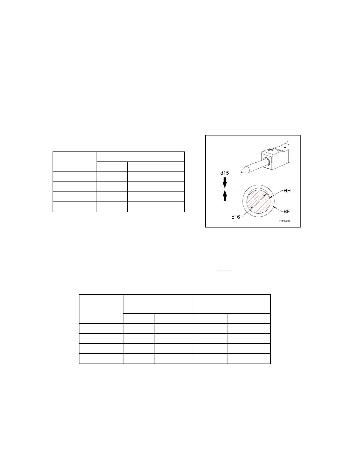
Replace the tool bushing (BF), and/or tool (HH), when the tool to bushing gap reaches
the maximum clearance. To determine whether the bushing or tool requires
replacement, follow the instructions and charts shown below:
Step 1
Measure the tool to bushing gap (d15) with the hammer horizontal, as illustrated below.
If the clearance is at or greater than the charted maximum clearance, then move on to
the next steps.
HAMMER MAXIMUM CLEARANCE
MODEL in (mm)
PH1
PH2
PH3
PH4
1/4
1/4
1/4
1/4
6
6
6
6
Step 2
Remove the tool from the tool holder. Measure the diameter (d16) of the bearing
surface of the tool (HH), which is located on each side of the retaining pin groove. The
minimum tool diameter is compared to a new tool bushing only. If the tool is at or below
the charted value, the tool must be replaced.
HAMMER NEW TOOL MINIMUM TOOL
MODEL DIAMETER DIAMETER
in (mm) in (mm)
PH1
PH2
2.24
2.60
(57)
(66)
2.02
2.37
(51.2)
(60.2)
PH3
PH4
2.99
3.38
(76)
(86)
2.76
3.16
(70.2)
(80.2)
- 52 -
Page 54

TOOLS
MAXIMUM TOOL TO TOOL BUSHING CLEARANCE
Step 3
Measure the inside diameter of the tool bushing. The maximum tool bushing inside
diameter is compared to a new tool only. If the tool bushing dimensions are at or above
the charted value, the bushing must be replaced.
HAMMER NEW BUSHING MAXIMUM BUSHING
MODEL INSIDE DIAMETER INSIDE DIAMETER
in (mm) in (mm)
PH1
PH2
PH3
PH4
Step 4
Compare the tool and bushing to the charts in Step 2 and Step 3. Choose the new
component (tool or bushing) that will bring the maximum clearance to below the value
seen in the chart of Step 1. Replacing both the tool and bushing would bring the
clearance back to new.
2.25
2.61
3.00
3.39
(57.2)
(66.2)
(76.2)
(86.2)
2.48
2.83
3.23
3.62
(63)
(72)
(82)
(92)
- 53 -
Page 55
TOOLS
TOOL INSPECTION
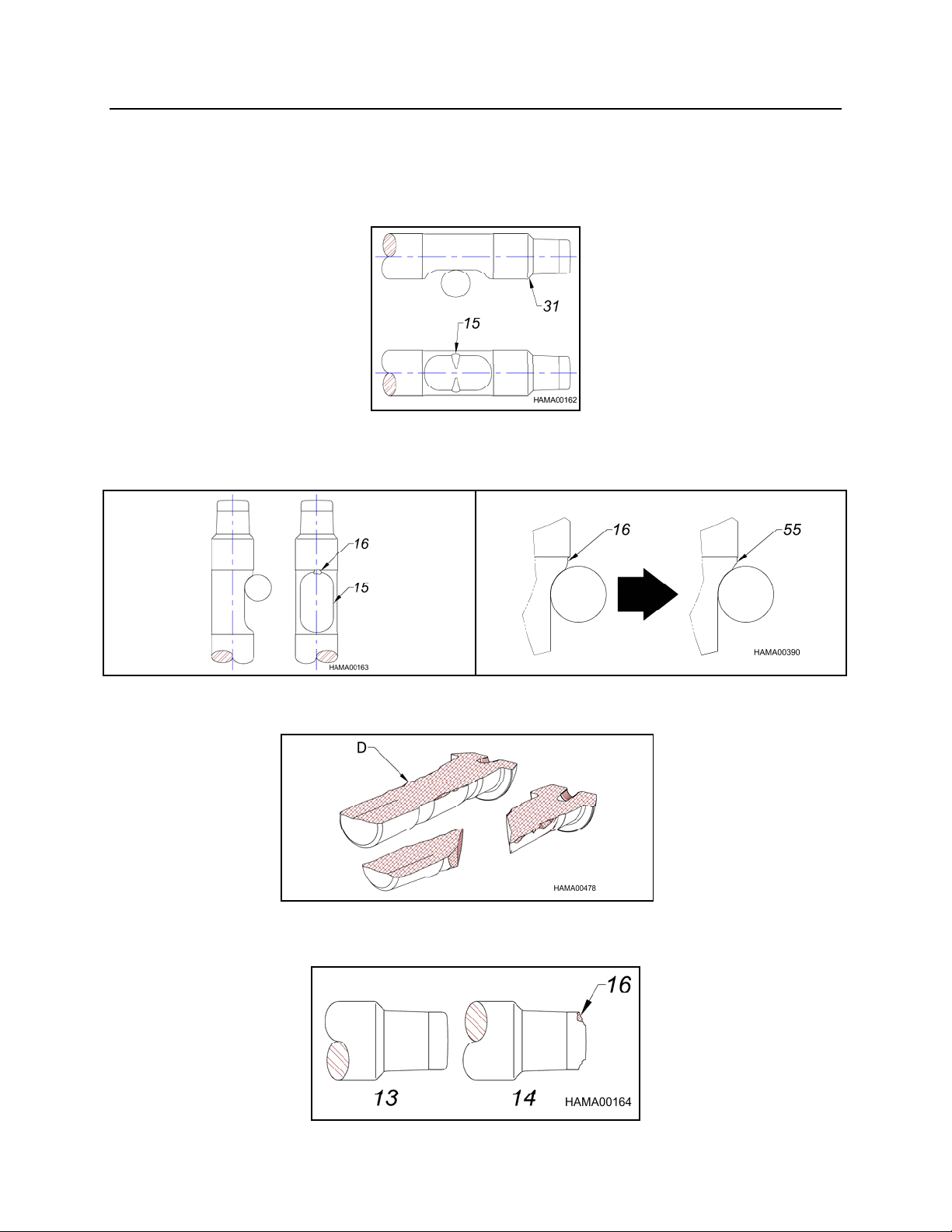
1. Deformation may occur on the tool in the retaining pin contact area (15) or thrust
surface (31). If these areas are mushroomed, the tool may become difficult to
remove from the tool holder. Dress with a grinder.
2. Excessive blank hammering will cause chipping (16) in the retaining pin contact area
(15). If neglected, the chipping may reduce the life or cause failure of the tool
retaining pin. Dress with a grinder.
3. Excessive blank hammering can cause retaining pin breakage/failure. Replace
retaining pin.
4. If chipping (16) is found at the top of the tool, replace the tool. If neglected, the
piston impact surface will be damaged (13 is normal, 14 needs to be replaced).
- 54 -
Page 56
TOOLS
CHISEL TOOL RESHARPENING
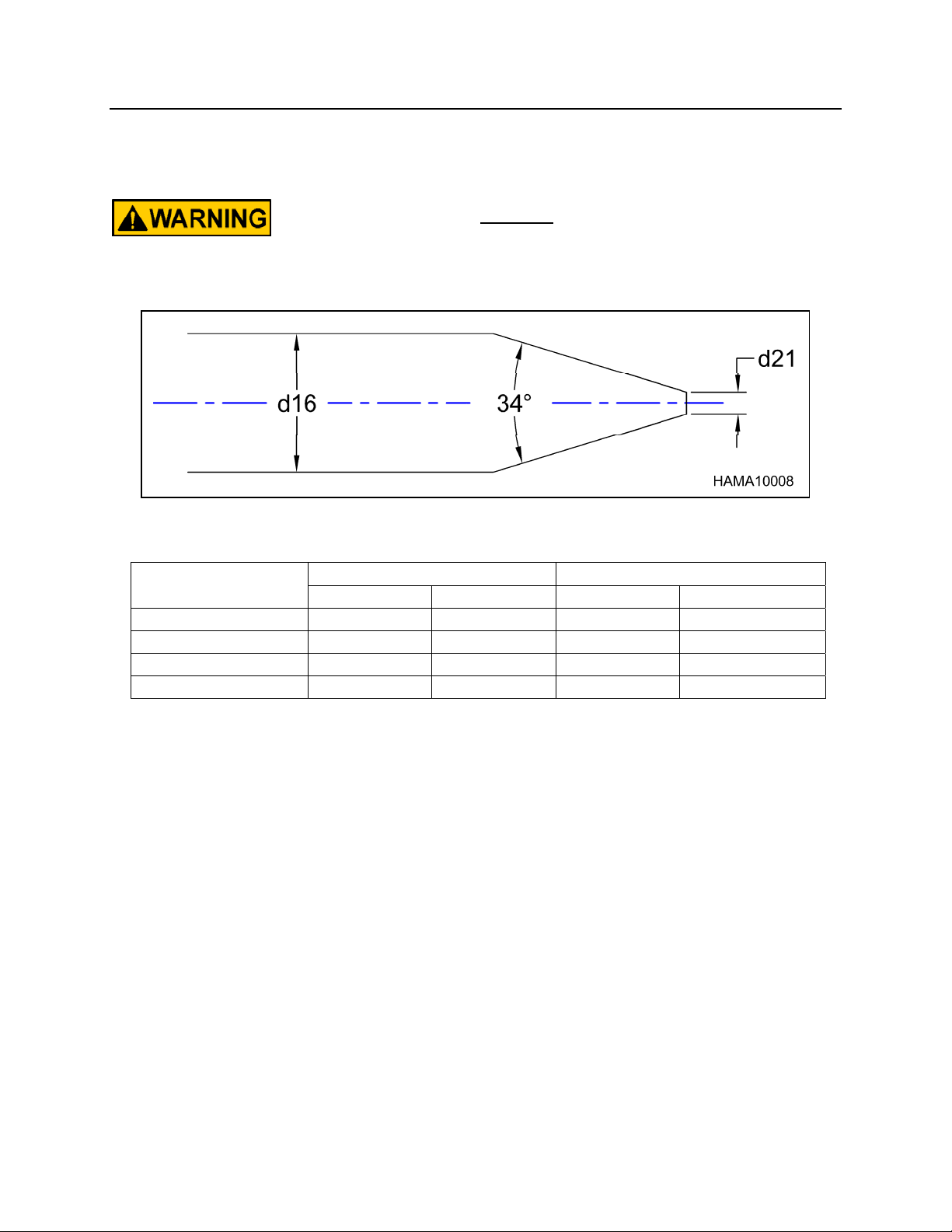
Worn chisel tools can be re-sharpened by machining according to
the dimensions below. DO NOT hardface or sharpen the tool point
with a cutting torch! Re-sharpen only with a lathe or milling
machine using sufficient coolant.
HAMMER
MODEL
PH1
PH2
PH3
PH4
in (mm) in (mm)
.39 (10) 2.24 (57)
.39 (10) 2.60 (66)
.39 (10) 2.99 (76)
.79 (20) 3.39 (86)
d21 d16 (ref)
- 55 -
Page 57
TOOLS
STANDARD LENGTH FOR NPK TOOLS
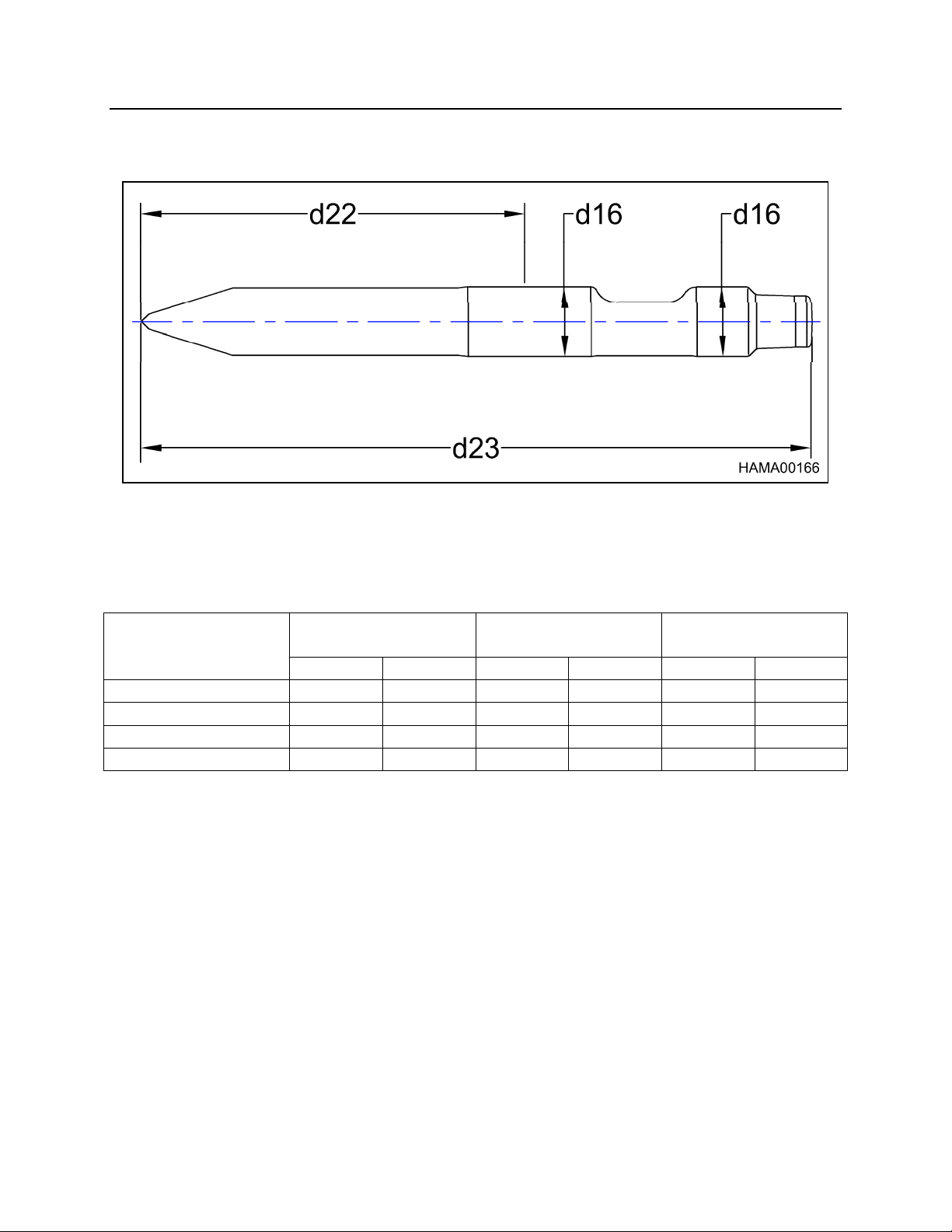
d23 = Length of tool from top to bottom.
d22 = Length of tool exposed from bottom of tool bushing to end of tool.
d16 = Diameter of bearing surface of tool.
HAMMER
MODEL
PH1
PH2
PH3
PH4
NOTE:
Minimum tool length is determined by the depth of material penetration that is required.
NEW TOOL
DIAMETER (d16)
in (mm) in (mm) in (mm)
2.24 (57) 23.6 (599) 14.1 (359)
2.60 (66) 25.5 (648) 15.1 (384)
2.99 (76) 28.5 (724) 16.5 (420)
3.39 (86) 33.0 (838) 18.5 (470)
NEW TOOL
LENGTH (d23)
NEW WORKING
LENGTH (d22)
- 56 -
Page 58
TOOLS
TOOL RETAINING PIN INSPECTION
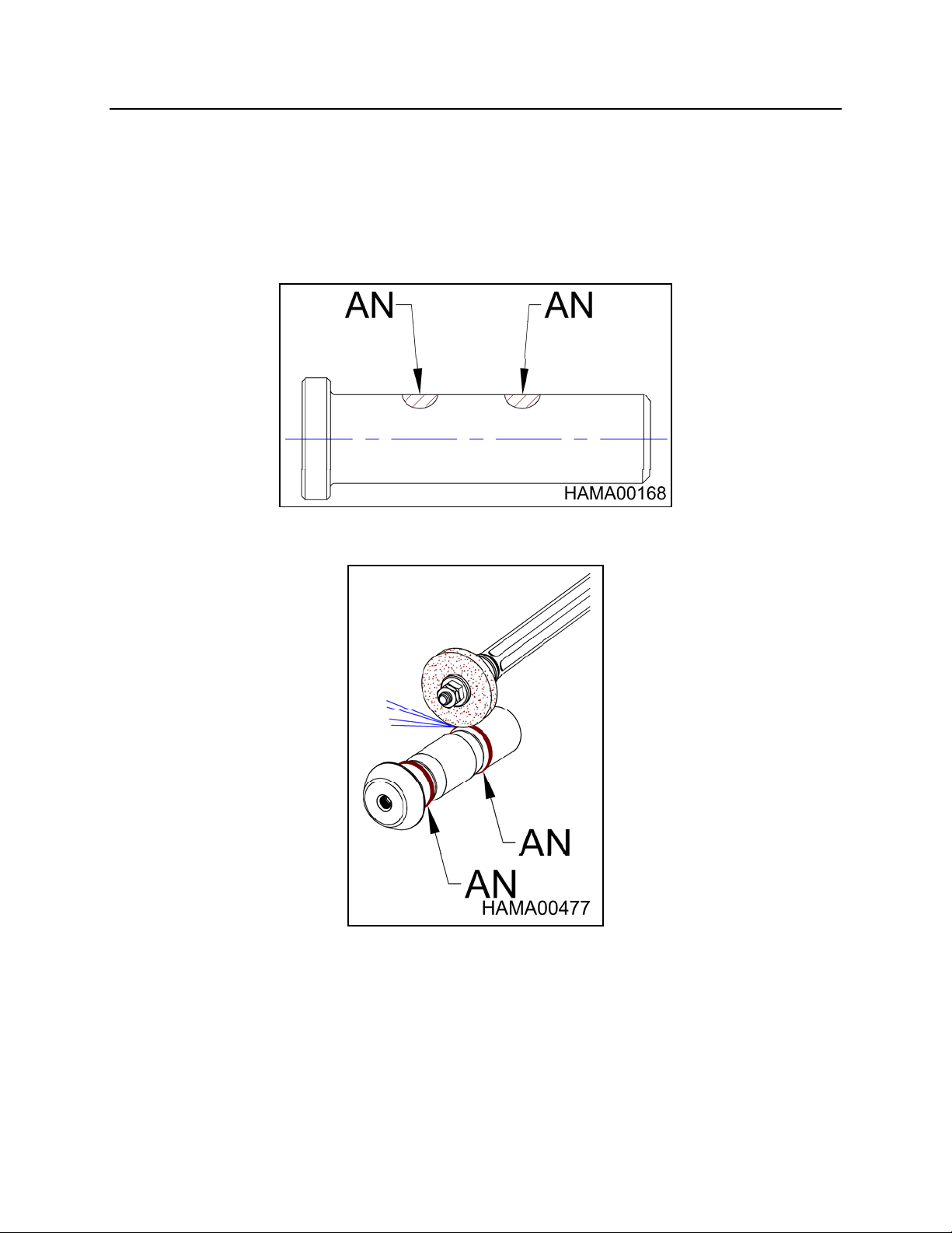
Deformation may occur on the retaining pin in the tool contact area (AN). If this area is
mushroomed, the retaining pin may become difficult to remove. Dress areas shown
(AN) with a grinder.
- 57 -
Page 59

TORQUE VALUES FOR HAMMER FASTENERS
If hammer bracket fasteners are found to be loose, use the following chart. If repairs
are to be made, see the NPK Hydraulic Hammer Service Manual.
HAMMER
MODEL
PH1 STANDARD 3/4"-10 280 (378) 5/8”-11 165 (225)
PH2 STANDARD 3/4"-10 280 (378) 5/8”-11 165 (225)
PH3 STANDARD 1”-12 500 (675) 5/8”-11 165 (225)
PH4 STANDARD 1”-12 500 (675) 5/8”-11 165 (225)
*Torque hammer bracket bolts using anti-seize compound.
**DO NOT torque adapter bracket bolts using anti-seize compound.
BRACKET
TYPE
SKID STEER 3/4"-10 280 (378) N/A N/A
HEAVY DUTY 5/8”-11 150 (203) 5/8”-11 165 (225)
SCALING 5/8”-11 150 (203) 5/8”-11 165 (225)
SKID STEER 3/4"-10 280 (378) N/A N/A
HEAVY DUTY 1”-12 500 (675) 5/8”-11 165 (225)
HEAVY DUTY 1”-12 500 (675) 5/8”-11 165 (225)
*HAMMER BRACKET **ADAPTER BRACKET
BOLT
DIA
BOLT TORQUE
ft/lbs (Nm)
BOLT
DIA
BOLT TORQUE
ft/lbs (Nm)
- 58 -
Page 60
GAS CHARGE
NITROGEN GAS PRESSURE
The nitrogen gas pressure must be measured with no preload on the tool. Remove the
tool; or position the hammer with the tool fully extended against the tool retaining pin.
The hammer must not be resting vertical on the tool. The gas pressure in the hammer
will vary according to the gas temperature.
PREFERRED METHOD
The preferred method to measure or charge the nitrogen gas pressure is with the
hydraulic system temperature stabilized at maximum operating temperature. The chart
showing values for “Operating Temperature” should be used, see below.
ALTERNATE METHOD
The nitrogen gas pressure can be measured or charged at ambient temperature (cold),
before operating the hammer. See the chart “Ambient Temperature” below.
DO NOT OVERCHARGE THE HAMMER!
Exceeding the gas pre-charge specifications can result in damaging hammer
components. The NPK WARRANTY does not cover failures resulting from exceeding
the specified nitrogen gas pressure.
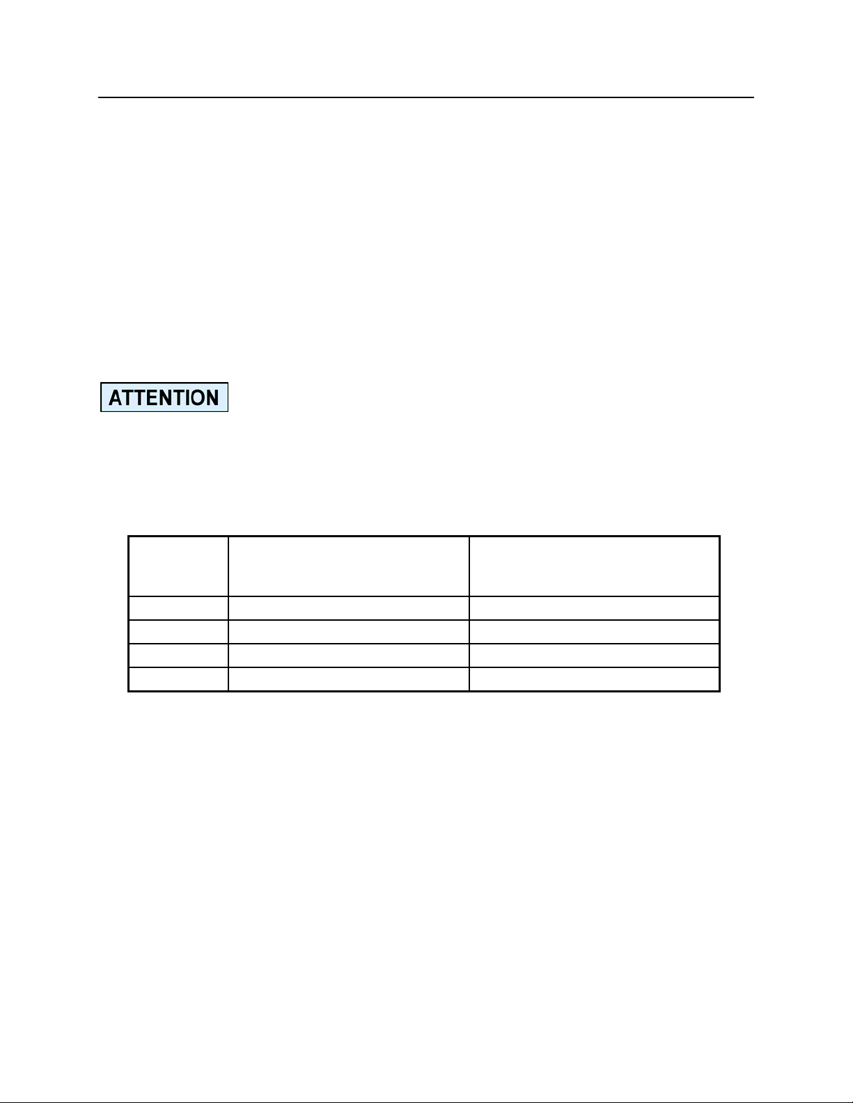
NITROGEN GAS PRE-CHARGE
HAMMER
MODEL
AT AMBIENT TEMPERATURE
(cold, before operating)
*psi (bar)
AT OPERATING TEMPERATURE
(hot, after 1 to 2 hrs. operation)
*psi (bar)
PH1 175 (12) 220 (15)
PH2 175 (12) 220 (15)
PH3 175 (12) 220 (15)
PH4 175 (12) 220 (15)
*The gas charge tolerance is plus 0, minus 25 psi (2 bar).
- 59 -
Page 61
GAS CHARGE
GAS CHARGING KIT
(Part Number 7300588)
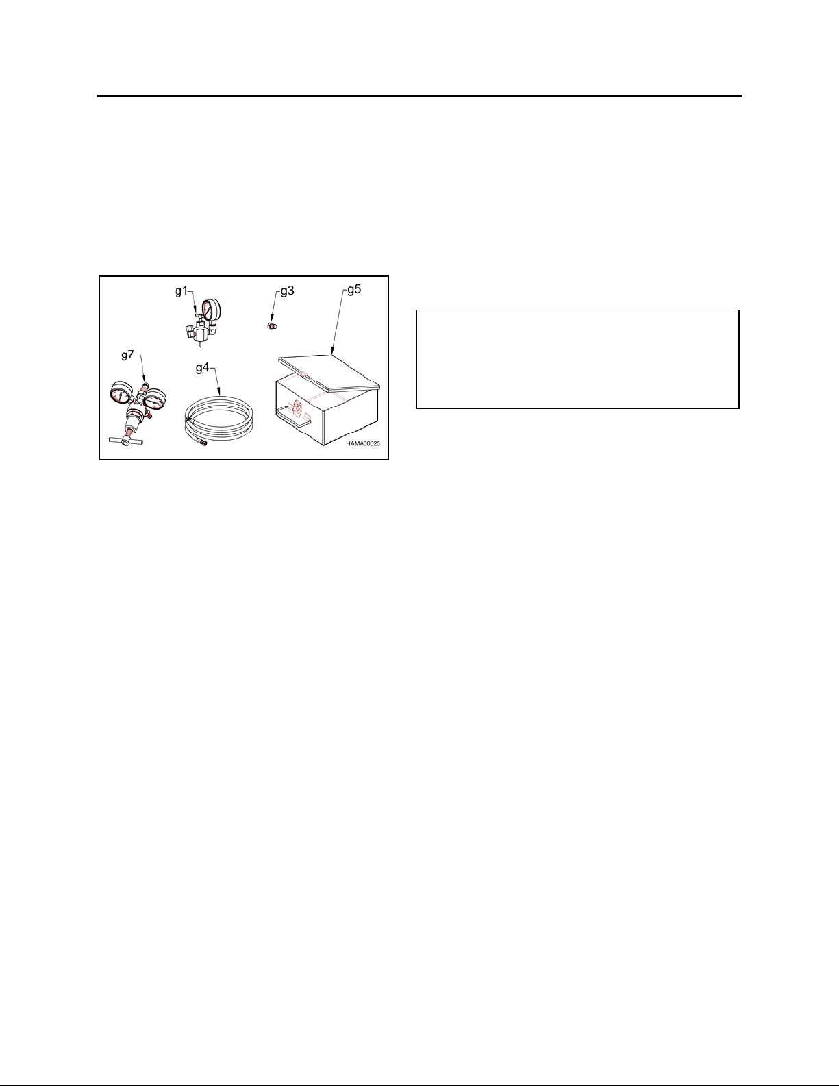
ALL NPK HYDRAULIC HAMMERS are furnished with the following gas charging kit. In
addition, a nitrogen tank and pressure regulator valve (not furnished with the hammer)
is required. These can be obtained from your local welding supply house. An optional
regulator valve, part no. 21101060, is available from NPK.
g1. CHARGE ADAPTER (PART NO. 30604040)
g3. PLUG (PART NO. 30102050)
g4. HOSE (PART NO. 20118010)
g5. CHARGING KIT BOX (PART NO. 35001030)
g7. OPTIONAL REGULATOR VALVE
(PART NO. 21101060)
- 60 -
Page 62
GAS CHARGE
CHECKING THE GAS PRESSURE
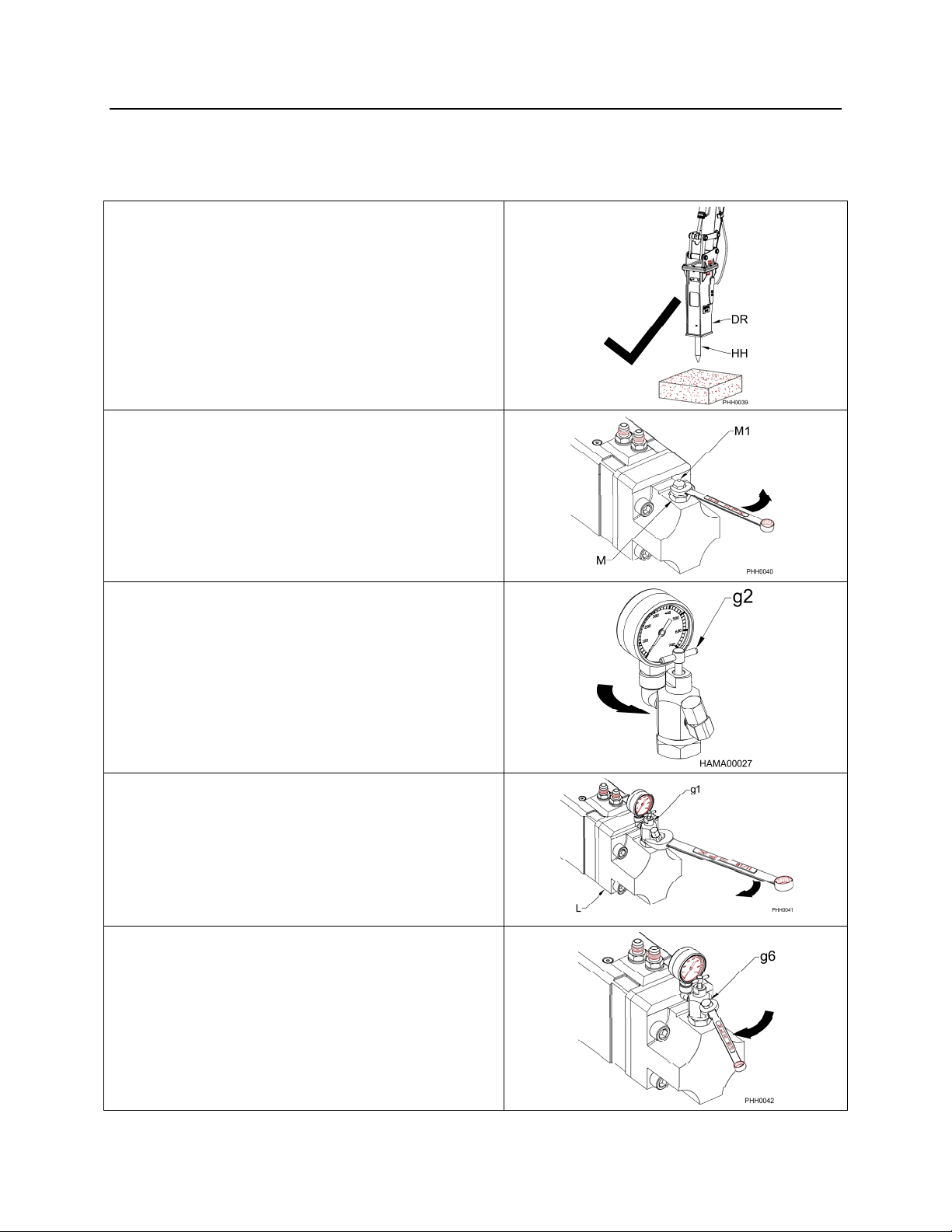
Inspect the nitrogen gas pressure every 100 hours.
PROCEDURE
1. The gas pre-charge is measured with no
preload on the tool (HH). Remove the tool
or position the hammer (DR) with the tool
fully extended.
2. Remove the charge valve cap (M1) from
the hammer charge valve (M). Do not
remove the charge valve assembly!
3. Turn the NPK charge adapter T-handle
(g2) to a full counterclockwise position.
4. Install the NPK charging adapter (g1) on
the hammer charge valve located on
hammer gas head (L).
5. Tighten the charge adapter cap (g6).
- 61 -
Page 63
GAS CHARGE
CHECKING THE GAS PRESSURE
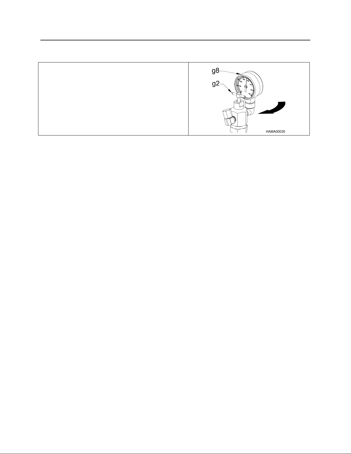
6. Turn the T-handle (g2) clockwise. As the
T-handle is screwed in, a resistance is
encountered. By turning the T-handle
further, the nitrogen gas pressure will be
indicated on the pressure gauge (g8). Stop
turning the T-handle when the gauge reads
pressure. Do not overtighten!
7. Compare the gauge pressure with the NITROGEN GAS PRE-CHARGE chart in the
NITROGEN GAS PRESSURE section. If the gas is 25 psi (2 bar) or more below the
specification, proceed to the NITROGEN GAS CHARGING PROCEDURE section of
the manual. If the pressure is correct, go to the next step.
8. Turn the T-handle counterclockwise until it stops, as in step 3.
9. Slowly loosen the charge adapter cap to relieve the nitrogen gas pressure trapped in
the charge valve.
10. Remove the charge adapter from the hammer charge valve.
11. Replace the charge valve cap on the charge valve.
- 62 -
Page 64
GAS CHARGE
CHARGING THE HAMMER
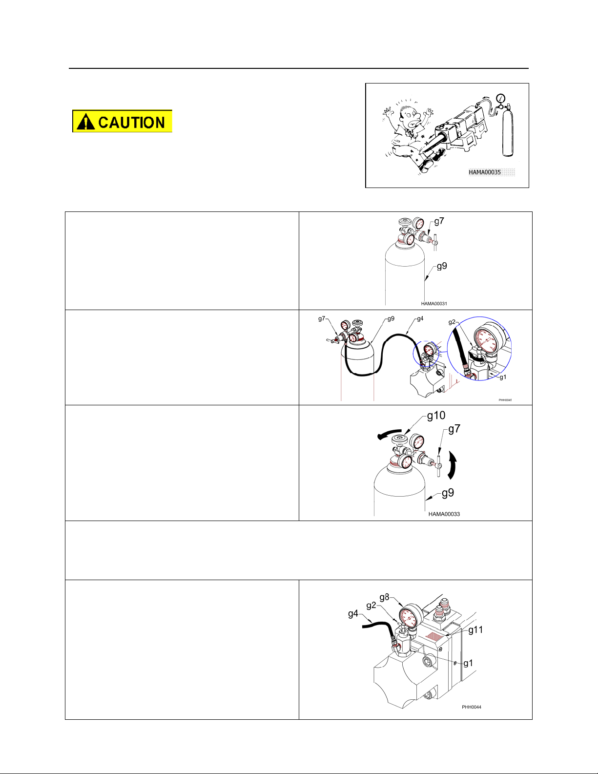
USE NITROGEN GAS ONLY.
STAY CLEAR OF THE TOOL WHILE CHARGING
THE HAMMER WITH GAS. The tool may be
impacted by the piston and forced out abruptly.
PROCEDURE
1. Carry out steps 1 thru 4 of CHECKING THE GAS PRESSURE.
2. Install a pressure regulator (g7) on a
tank (g9) of nitrogen gas.
3. Connect a hose (g4) from the pressure
regulator (g7) on the nitrogen tank (g9)
to the charge adapter (g1).
4. Turn the T-handle (g2) on the charge
adapter (g1) clockwise.
5. Turn the handle (g7) on the tank
regulator counterclockwise to a fully
closed position. Do not overtighten!
6. Open the valve (g10) on the nitrogen
tank (g9) by turning the handle
counterclockwise.
7. Slowly adjust the regulator on the nitrogen tank to the correct pressure by turning the
handle (g7) clockwise. Refer to the NITROGEN GAS PRE-CHARGE chart in the
NITROGEN GAS PRESSURE SECTION.
8. Charge the nitrogen gas, per the gas
charge decal (g11), until the pressure
gauge (g8) on the charge adapter (g1)
is at the correct setting, then turn the Thandle (g2) counterclockwise all the
way out.
9. Close the nitrogen tank valve (g10),
then, remove the hose (g4) from the
charge adapter (g1).
- 63 -
Page 65
GAS CHARGE
DISCHARGING THE GAS PRESSURE
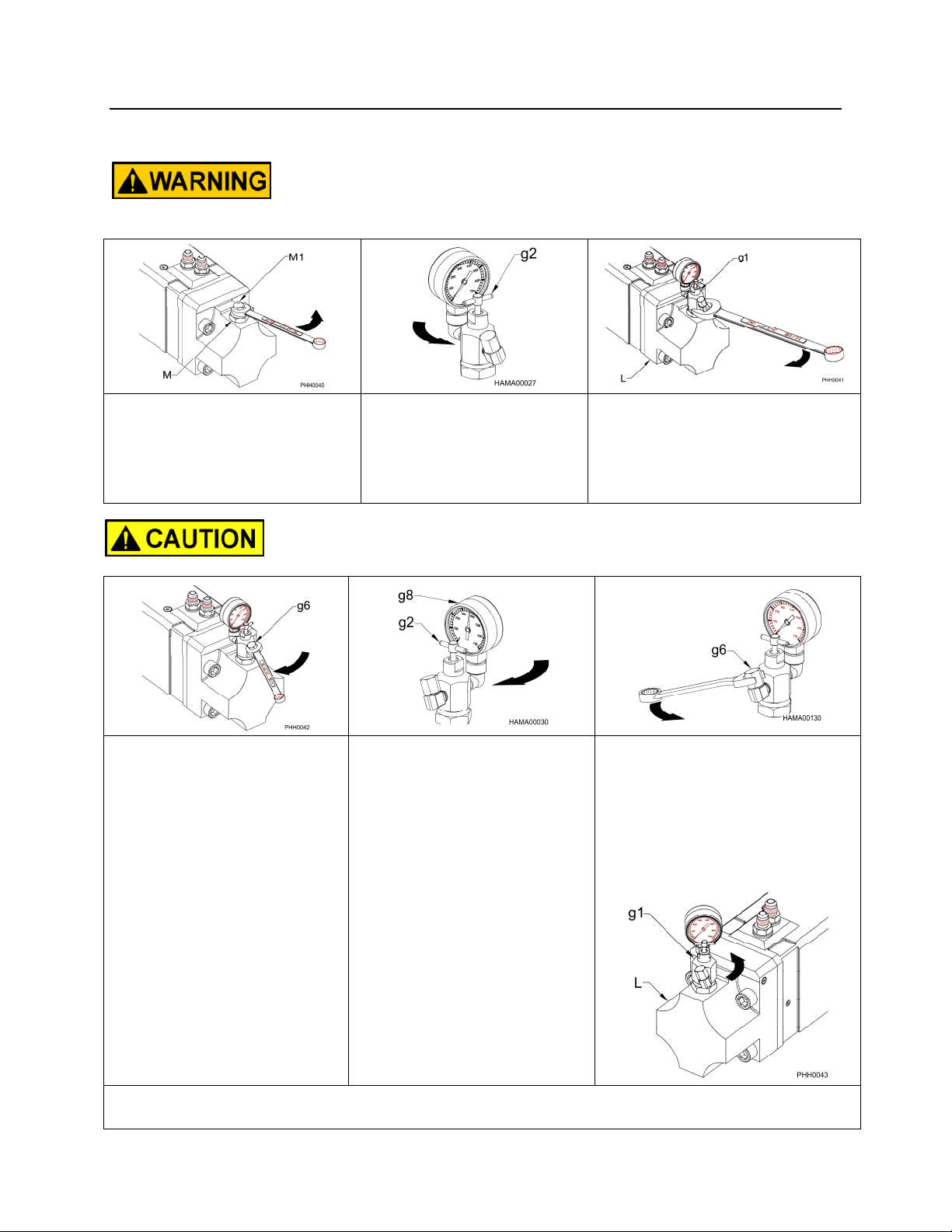
THE NITROGEN GAS MUST BE DISCHARGED FROM THE
PROCEDURE
HAMMER BEFORE DISASSEMBLY!
1. Remove the charge valve
cap (M1) from the charge
valve (M). Do not
remove the charge
valve assembly!
REMOVE THE VALVE CAP ONLY, NOT THE CHARGE VALVE
ASSEMBLY!
4. Tighten the charge
adapter cap (g6).
2. Turn the NPK charge
adapter T-handle (g2)
to a full
counterclockwise
position.
5. Turn the T-handle (g2)
clockwise. As the Thandle is screwed in, a
resistance is
encountered. By turning
the T-handle, the
nitrogen gas pressure
will be indicated on the
pressure gauge (g8).
Stop turning the Thandle when the gauge
reads pressure. Do not
over tighten!
3. Install the NPK charge
adapter (g1) onto the
hammer charge valve
located on the hammer gas
head (L).
6. Loosen the charge
adapter cap (g6) VERY
SLOWLY! The gas
pressure will gradually
decrease to zero. When it
gets to zero, remove the
cap.
7. Remove the charge adapter (g1) from the gas charge valve on the hammer gas head
(L), and then reinstall the charge valve cap.
- 64 -
Page 66
STORAGE OF HYDRAULIC HAMMER
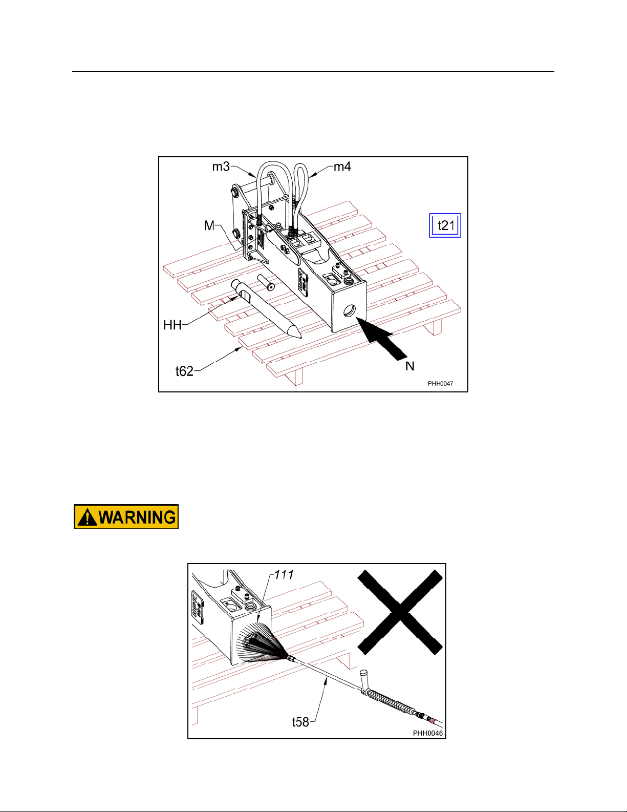
For short term storage between jobs, place the hammer horizontal on a pallet (t62). Be
sure that the tool end of the hammer is lower than the gas end. Also, be sure the tool
(HH) is liberally greased and the hydraulic hoses (m3 and m4) are capped. Cover with
a waterproof tarp (t21), not shown.
If the NPK HYDRAULIC HAMMER is not to be used for a long period of time (months),
it is recommended the gas pressure be discharged at the charge valve (M). The tool
(HH) should be removed, and the piston (N) pushed all the way in. Be sure the
hydraulic hoses (m3 and m4) are plugged and grease the exposed end of the piston
(N). Grease and reinstall the tool (HH). Cover with a waterproof tarp (t21), not shown.
DO NOT CLEAN the tool holder bore (111) of the hammer with
a steam cleaner or high pressure washer (t58). This could
cause rust to form, then in turn, cause damage to the hammer
piston!
- 65 -
Page 67

WARRANTY REGISTRATION FOR NEW UNITS
Complete and send to NPK after installation or complete on line at www.npkce.com.
Online warranty registration can be done by the dealer or the end user.
The registration can be done in any of the following ways:
1. Mailed to:
NPKCE
7550 Independence Dr.
Walton Hills Ohio 44146
2. Faxed: 440-232-6294(U.S.) (+1)(440)232-6294(outside U.S.)
3. Completed online at :
www.npkce.com
The online registration can be done by the dealer or the end user.
Dealers:
In the tool bar click on DEALERS.
Using your user name and password, log into the system.
At the left of the next page click on REGISTRATION.
Complete the fields with an orange diamond next to them.
At the bottom of this area, click the START REGISTRATION box and continue.
If the registration is completed online, there is no need to mail or fax the warranty
registration.
End users / non NPK dealers
In the tool bar click on DEALERS
You do NOT need to fill in user name and password.
In the left column, click on the REGISTRATION.
Complete the fields with an orange diamond next to them.
At the bottom of this area, click the START REGISTRATION box and continue.
If the registration is completed online, there is no need to mail or fax the warranty
registration.
- 66 -
Page 68
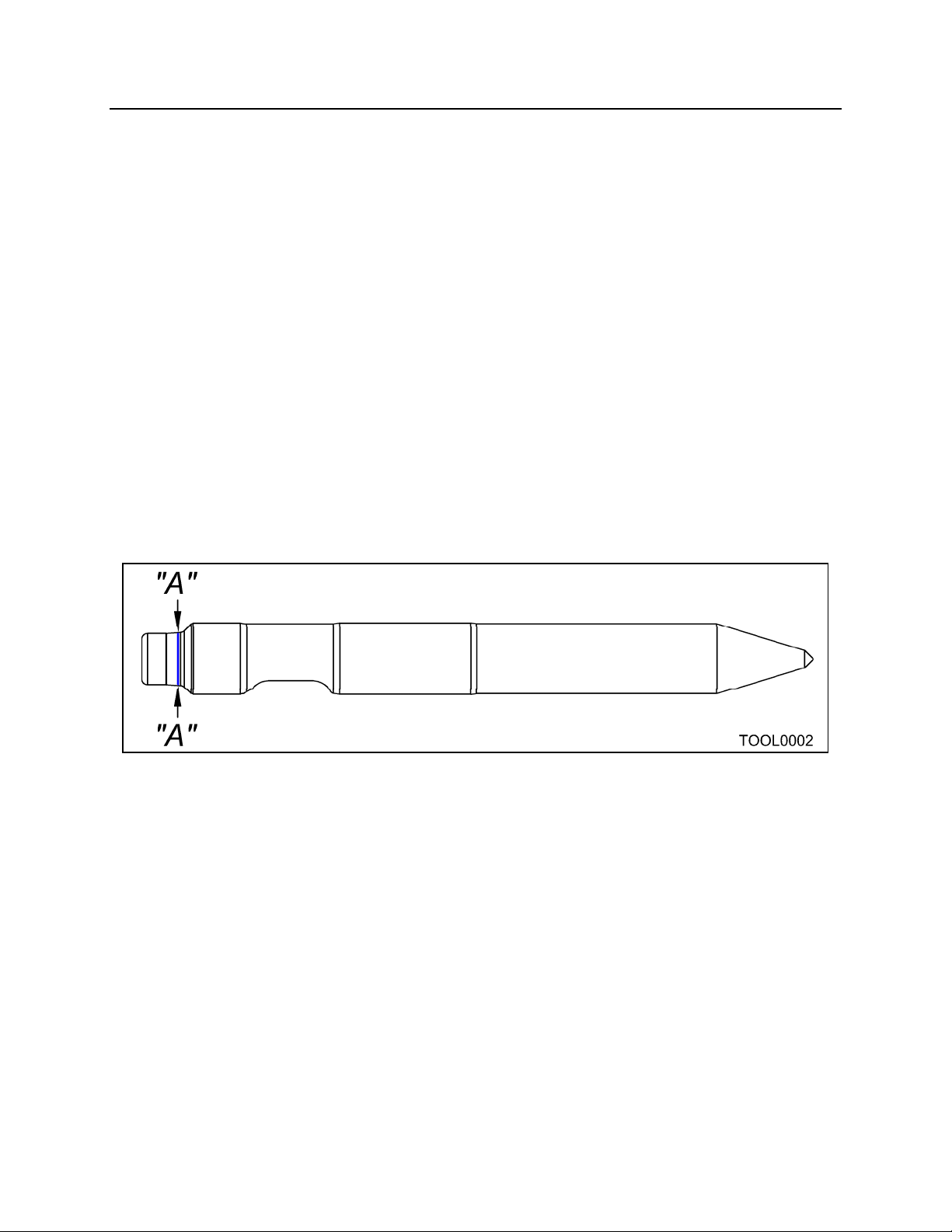
TOOL WARRANTY
STANDARD DEMOLITION and ACCESSORY TOOLS WARRANTY (30 days)
NPK Construction Equipment, Inc. (“NPK”) warrants that new Standard Demolition
Tools, and other Standard Accessory Tools sold by NPK will be free from defects in
material or workmanship for a period of thirty (30) days, starting from the date of
installation. NPK reserves the full right to determine if, and to what extent, warranty
adjustments may be made for breakage of the demolition or other accessory tools.
NPK Tool Warranty does not cover labor or travel expenses.
THIS WARRANTY DOES NOT APPLY TO:
Custom or special application tools which are excluded from warranty.
NPK RESPONSIBILITY
NPK will, at its option, replace with a new or reconditioned tool, any warranted tool that
fails by reason of defective material or workmanship, free of charge, delivered at a place
of business of an NPK Dealer. Tool breakage is specifically covered ONLY for straight
across breakage as shown at locations A: Note: The tool to bushing gap must be
verified and reported to NPK. Failure to provide this information will make this failure
non-warrantable, see pages 39 and 40.
For warranted tool failures, a prorated credit, up to 80% maximum, will be issued
for tools with tip wear greater than 50 mm on chisel and moil points, or 30 mm on
blunt end tools. Note: Parts replaced under warranty become the property of
NPK.
- 67 -
Page 69
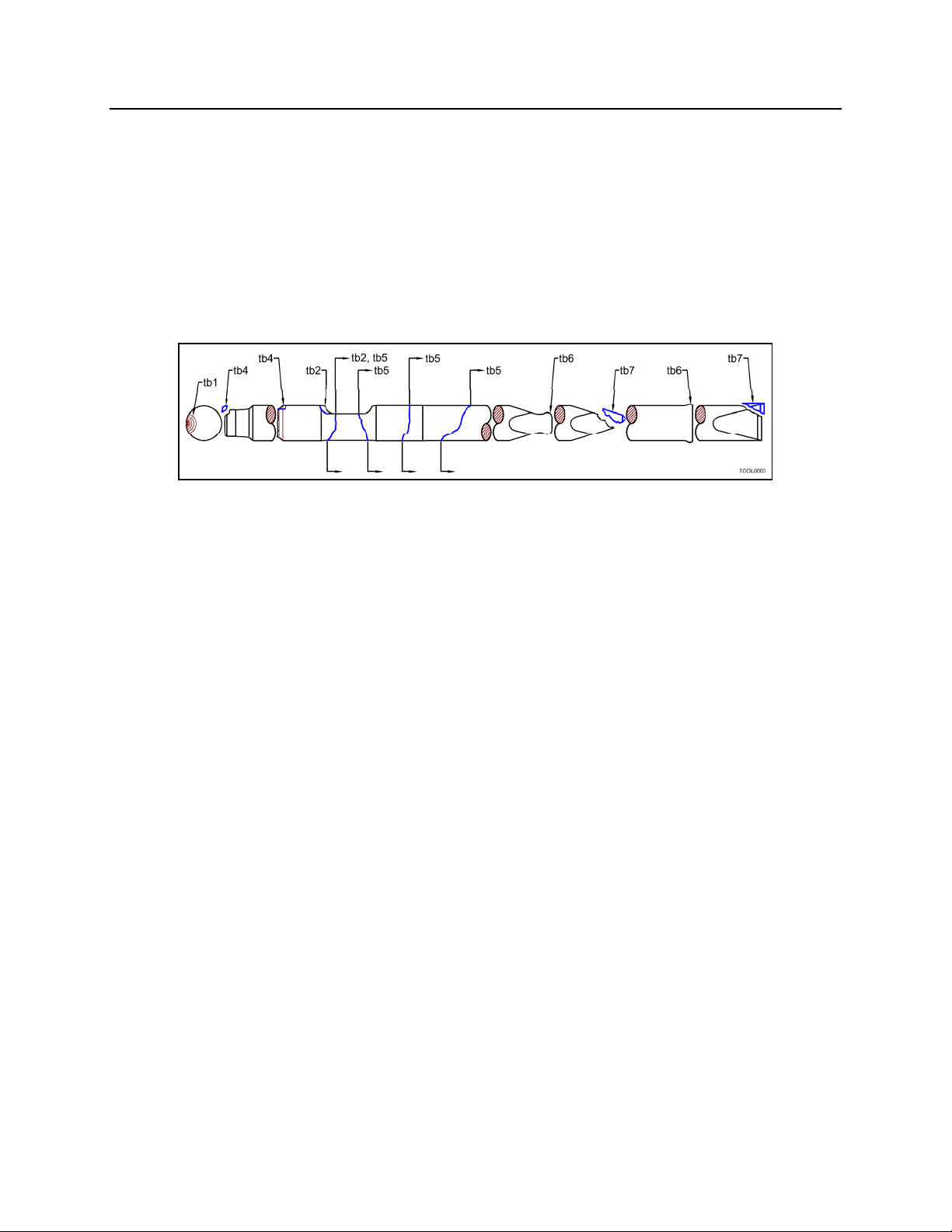
TOOL WARRANTY
USER RESPONSIBILITY
Photos and all numbers from retaining pin slot must accompany all warranties
submitted to NPK. These photos can be 35 mm, Polaroid, or digital.
The installer, user, operator, repairer, assumes responsibility to read, understand
and comply with NPK’s written INSTALLATION, OPERATOR, and SERVICE
INSTRUCTIONS.
All labor costs.
Any expense incurred by field repair.
Tool failures as shown at locations B (see NPK Operators Manual for correct
operating procedures):
CAUSE
FAILURE
OF
tb1 – Typical break from bending
overload.
tb2 and tb3 – repeated blank hammering.
tb3 – bending overload due to excessive
wear of the tool bushings.
tb4 – corner loading due to excessive
wear of the tool bushings.
tb5 – bending overload from excessive
prying or slant hammering.
tb6 – deformation from overheating by
hammering in the same position for more
than 30 seconds.
tb7 – chipped, due to wrong application,
or overheating by hammering in same
position for over 30 seconds.
THESE WARRANTIES DO NOT COVER FAILURES RESULTING FROM:
Installation, alteration, operation, maintenance, repair or storage which NPK judges
improper.
Inadequate lubrication.
Exceeding the tool and/or tool bushing wear limit.
Unreasonable delay in making a repair after being notified of a potential product
problem.
THESE WARRANTIES SPECIFICALLY EXCLUDE:
Any tool which is altered, welded, hardfaced or re-sharpened.
Replacement due to tip or shank wear.
Installations not approved by NPK.
Use of parts not sold by NPK. THE USE OF “WILL FIT” PARTS WILL VOID THE
WARRANTIES OF ANY AND ALL PARTS DAMAGED AS A RESULT OF THE
FAILURE OF THE “WILL FIT” PARTS.
Parts shipping charges in excess of those which are usual and customary. (Air
freight, unless pre-approved, will not be covered).
Duties, brokerage fees, and local taxes.
WARRANTY REPAIRS DO NOT EXTEND THE STANDARD WARRANTY PERIOD.
LIMITATIONS AND EXCLUSIONS
Violation of any federal, provincial, state or local laws, ordinances, rules or regulations,
or removal or alteration of product serial numbers void NPK’s written product
warranties. Application for warranty must be made within 30 days of failure.
- 68 -
Page 70
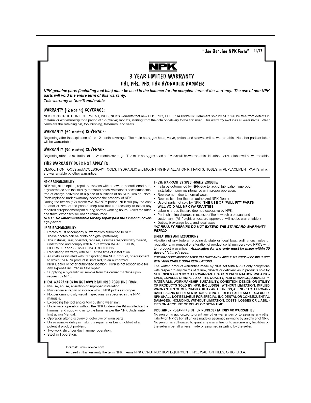
WARRANTY STATEMENTS
- 69 -
Page 71
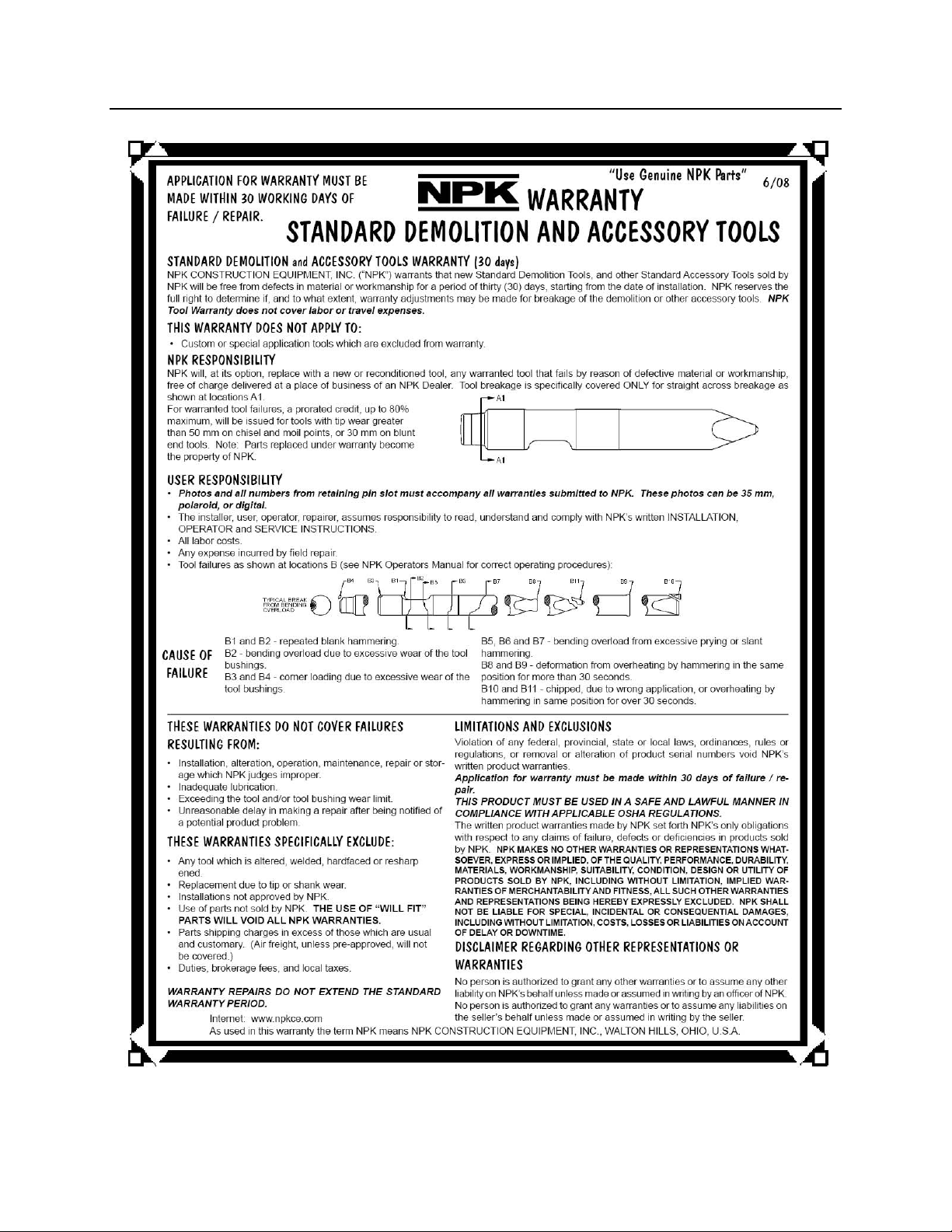
WARRANTY STATEMENTS
- 70 -
Page 72
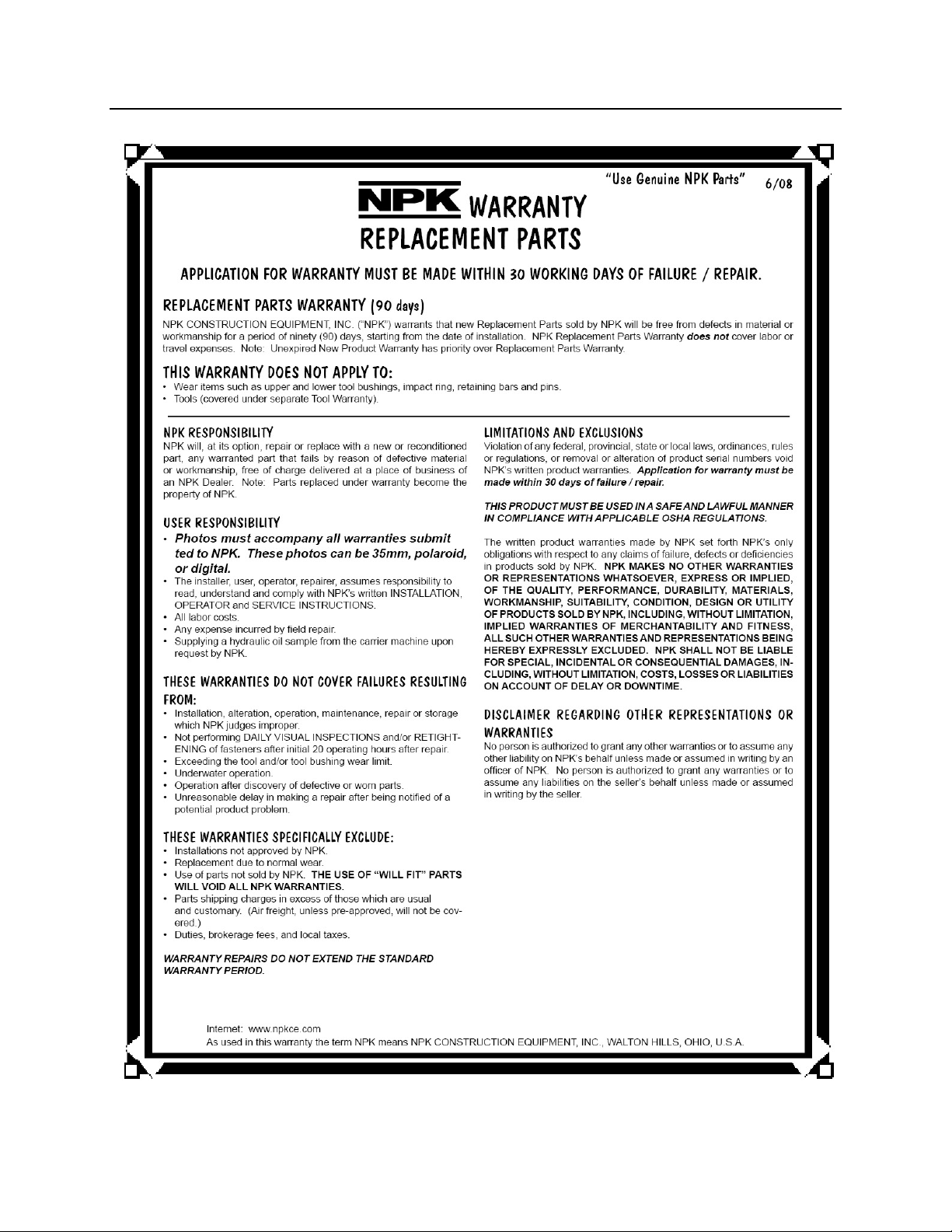
WARRANTY STATEMENTS
- 71 -
Page 73
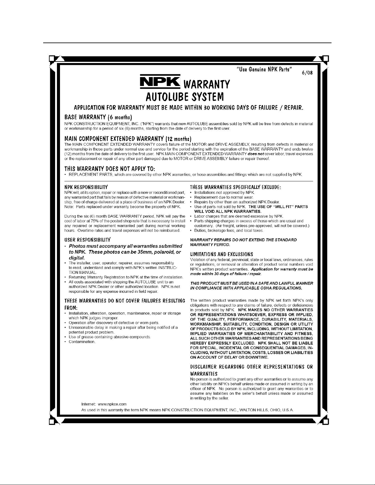
WARRANTY STATEMENTS
- 72 -
Page 74

NOTES AND RECORDS
NPK HYDRAULIC HAMMER MODEL NUMBER _______________
SERIAL NUMBER _______________
NPK INSTALLATION KIT NUMBER ___________________________
CARRIER MANUFACTURER
MODEL NUMBER
SERIES
SERIAL NUMBER
DATE OF INSTALLATION _________________
DATE OF 20 HOUR INSPECTION ___________ WARRANTY REGISTRATION SENT
- 73 -
Page 75

© Copyright 2016 NPK Construction Equipment, Inc. www.npkce.com H050-9660C PH1, PH2, PH3,
PH4 Operators Manual 3-16
 Loading...