

Page 1

DG16
DG20
DG30
DG40
DEMOLITION GRAB
INSTRUCTION MANUAL
MODELS:
“Use Genuine NPK Parts”
7550 Independence Drive
Walton Hills, OH 44146-5541
Phone (440) 232-7900
Toll-free (800) 225-4379
Fax (440) 232-6294
© Copyright 2018 NPK Construction Equipment, Inc. www.npkce.com DG000-9600A
DG16,DG20,DG30,DG40 Demolition Grab Instruction Manual 6-18
Page 2

CONTENTS
CONTENTS .............................................................................................................................................. 1
SAFETY .................................................................................................................................................... 3
OPERATION ...................................................................................................................................... 4
MAINTENANCE ................................................................................................................................. 5
INTRODUCTION ....................................................................................................................................... 7
EXCAVATOR COMPATIBILITY ................................................................................................................. 7
SERIAL NUMBER LOCATION .................................................................................................................. 8
SPECIFICATIONS ..................................................................................................................................... 9
DG16 ................................................................................................................................................. 9
DG20 ................................................................................................................................................. 10
DG30 ................................................................................................................................................. 11
DG40 ................................................................................................................................................. 12
HYDRAULIC INSTALLATION .................................................................................................................... 13
HYDRAULIC LINES ........................................................................................................................... 13
SHUT-OFF VALVES .......................................................................................................................... 13
PORT CONNECTION DIAGRAM ....................................................................................................... 14
DEMOLITION GRAB HYDRAULIC CIRCUITS ........................................................................................... 15
MOUNTING INSTALLATION ..................................................................................................................... 18
MOUNTING TO THE EXCAVATOR ................................................................................................... 19
REMOVAL FROM THE CARRIER ..................................................................................................... 19
STORAGE OF DEMOLITION GRAB ......................................................................................................... 19
OPERATING INSTRUCTIONS .................................................................................................................. 20
OPERATING TECHNIQUES AND PRECAUTIONS............................................................................ 22
GENERAL MAINTENANCE ....................................................................................................................... 25
DAILY INSPECTION AND MAINTENANCE ....................................................................................... 25
ARM MAINTENANCE ........................................................................................................................ 26
FRAME MAINTENANCE .................................................................................................................... 26
FRAME CRACK REPAIR ................................................................................................................... 26
LUBRICATION POINTS ..................................................................................................................... 27
SLEWING RING INSPECTION AND MAINTENANCE ............................................................................... 28
MEASURING MAXIMUM AXIAL MOVEMENT ................................................................................... 28
NPK ASSEMBLY LUBRICANT .................................................................................................................. 29
ROTARY JOINT MAINTENANCE .............................................................................................................. 30
HYDRAULIC ROTARY JOINT ASSEMBLY ........................................................................................ 30
LEAKAGE OF THE SEALS ................................................................................................................ 30
TESTING THE ROTARY JOINT SEALS FOR INTERNAL LEAKAGE ................................................. 30
REPLACEMENT OF THE SEALS IN THE ROTARY JOINT ............................................................... 31
TROUBLESHOOTING ............................................................................................................................... 35
DETERMINE THE TYPE OF PROBLEM ............................................................................................ 35
MEASURING OPERATING PRESSURES ......................................................................................... 35
RELIEF VALVE CHECKING AND SETTING PROCEDURE ............................................................... 35
COUNTERBALANCE VALVE LOCATION .......................................................................................... 37
TROUBLESHOOTING CHART FOR LOW POWER ........................................................................... 38
CHECKING HYDRAULIC FLOW AT RATED PRESSURE ................................................................. 39
PROCEDURE FOR CHECKING HYDRAULIC FLOW AT RATED PRESSURE .................................. 39
TROUBLESHOOTING CHART FOR SLOW CYLINDER SPEED ....................................................... 41
JAW DRIFT........................................................................................................................................ 41
TO DETERMINE IF THE JAW DRIFT IS OCCURING FROM A BAD CYLINDER OR THE CARRIER. 41
ROTATION ........................................................................................................................................ 42
MEASURING ROTATION PRESSURES ............................................................................................ 42
ROTATION PRESSURE CHECKING PROCEDURE .......................................................................... 43
TROUBLESHOOTING CHART FOR ROTATION ............................................................................... 43
FASTENER TORQUE CHART .................................................................................................................. 45
CYLINDER TORQUE SPECIFICATIONS .................................................................................................. 47
ROD NUT AND PISTON TORQUES .................................................................................................. 47
CONVERT FROM DUAL MOTOR TO SINGLE MOTOR (DG20, DG30, DG40).......................................... 48
1
Page 3

CONTENTS
WARRANTY STATEMENTS ..................................................................................................................... 49
KEYWORDS FOR COMMON DEMO GRAB COMPONENTS .................................................................... 51
NOTES...................................................................................................................................................... 52
SERVICE RECORD .................................................................................................................................. 52
2
Page 4
SAFETY
Safety notices in NPK Instruction Manuals follow ISO and ANSI standards for
safety warnings:
DANGER (red) notices indicate an imminently hazardous
situation which, if not avoided, will result in death or
serious injury.
WARNING (orange) notices indicate a potentially hazardous
situation which, if not avoided, could result in death or
serious injury.
CAUTION (yellow) notices indicate a potentially hazardous
situation, which, if not avoided, may result in minor or
moderate injury.
ATTENTION (blue) notices in NPK Instruction Manuals are
an NPK standard to alert the reader to situations which, if not avoided, could result in
equipment damage.
WARNING – FALLING OR FLYING DEBRIS decals are
included with each NPK Demolition Grab Attachment. The
decal (part number H100-7210) must be installed in the cab,
visible to the operator.
WARNING – STAY CLEAR decal (part number H100-7200)
is installed on all NPK Demolition Grab Attachment. Keep
them clean and visible. NPK will provide decals free of
charge as needed.
3
Page 5

Warning Decal for Cab Installation
SAFETY
OPERATION
1. Operator personnel must read and understand the NPK INSTRUCTION MANUAL
to prevent serious or fatal injury.
2. FLYING OR FALLING DEBRIS CAN CAUSE SERIOUS OR FATAL INJURY.
Keep personnel and bystanders clear of the DEMOLITION GRAB while in
operation.
3. Do not operate DEMOLITION GRAB without an
impact resistant shield between the DEMOLITION
GRAB and operator. Operate with extreme caution
near walls or columns that may collapse and near
concrete debris that may fall.
4. Operate the DEMOLITION GRAB from the
operator’s seat only.
5. Use two people whenever operator visibility is
limited, one to operate the DEMOLITION GRAB,
the other to guide operations.
6. Do not leave a load suspended in air.
7. Do not pass a load over people, vehicles, etc.
8. Do not operate the DEMOLITION GRAB within
reach of power lines.
9. Do not climb, sit, or ride on the DEMOLITION
GRAB.
10. Match the DEMOLITION GRAB size to excavator according to NPK
recommendations, see page 7. The excavator must be stable during DEMOLITION
GRAB operation and during transport.
11. Do not operate without inspection (access) covers in place.
12. Be especially cautious around hydraulic lines. Hydraulic oil can be extremely HOT!
Avoid skin contact with hydraulic oil. It can cause severe burns!
13. Protect hands and body from hydraulic fluids under pressure. Escaping high
pressure fluid can penetrate the skin, causing serious injury. Avoid the hazard by
relieving pressure before disconnecting any lines. Search for leaks with a piece of
cardboard, or other object. If an accident occurs, see a doctor immediately!
Hydraulic fluid injected into the skin must be surgically removed immediately
or gangrene may result!
14. Make daily visual inspections of all fasteners, boom pins, hoses, etc.
15. When removing or installing mounting pins, beware of flying metal chips.
4
Page 6

SAFETY
MAINTENANCE
1. Use only NPK supplied replacement parts. NPK specifically disclaims any
responsibility for bodily injury or DEMOLITION GRAB damage that results from the
use of parts not sold or approved by NPK.
2. Use extreme caution in handling. A fully assembled DEMOLITION GRAB can
weigh over 2 tons. Sub-assemblies range in weight from hundreds to thousands of
pounds. To avoid bodily harm, use lifting and securing mechanisms of adequate
capacity to support loads. Seek the aid of an assistant as much as possible, and
always when handling heavier sub-assemblies.
3. The supplied safety bar (t79) MUST always be installed during transport, repairs,
dismounting and mounting to the carrier, changing the cutters and all other routines
at the attachment (GZ).
4. Wear safety glasses and protective clothing when working on the DEMOLITION
GRAB. Wear thermal-protective gloves when handling heated parts.
5. Prevent exposure to hazardous fumes. Remove all paint, grease, and oil before
heating, cutting or welding on the DEMOLITION GRAB.
6. Be especially cautious around hydraulic lines. Hydraulic oil can be extremely HOT!
Avoid skin contact with hydraulic oil. It can cause severe burns!
7. Protect hands and body from hydraulic fluids under pressure. Escaping fluid
under pressure can penetrate the skin, causing serious injury. Avoid the hazard by
relieving pressure before disconnecting any lines. Search for leaks with a piece of
cardboard, or other object. If an accident occurs, see a doctor immediately!
Hydraulic fluid injected into the skin must be surgically removed within a few
hours or gangrene may result.
8. When removing or installing mounting pins, beware of flying metal chips.
5
Page 7

SAFETY
ATTENTION
MAINTENANCE
STANDARD PRACTICES
Maintenance of and repairs to the DEMOLITION GRAB should be performed by an
experienced service technician, thoroughly familiar with all standard practices and
procedures, and most importantly, all safety precautions. The following is a review of
common standard practices to be followed when working with hydraulic equipment, and
is not meant to be all-inclusive. Rather, this review is presented as a reminder as to
some of the unique characteristics of hydraulic equipment.
The prevention of foreign contaminant damage is critical when working with
hydraulic equipment. Protect exposed holes and parts to guard against entry of
contaminants. Install metal or plastic plugs/caps where applicable to prevent entry
of debris into the hydraulic system.
Mark the location and position of mating parts as an aid to re-assembly. Mark
corresponding parts uniquely to reflect their relationship, including proper location,
position, orientation, and/or alignment.
DO:
During assembly, observe all markings made during disassembly, and all
corresponding features of mating parts to ensure proper location, position,
orientation, and alignment.
During disassembly of a sub-assembly, place removed components on a clean, dry
surface, in proper relative position as an aid in re-assembly.
Always inspect threaded areas on components. Repair or replace as required.
Never apply uncured thread adhesive to a fastener that has cured adhesive on it.
Clean the fastener and the threaded bore. A tap and die may be helpful for this task.
Be sure to remove loose debris from the threaded bore.
Use care to avoid scratches, nicks, dents, or other damage to machined surfaces of
mating components.
When securing a component, always tighten cap screws gradually in an opposing
pattern, applying the specified torque.
Grease can be used to temporarily hold a part in place while the abutting part is
placed into position.
Always use common sense and exercise standard safety precautions when working
with all tools and equipment required to maintain, repair or troubleshoot the
DEMOLITION GRAB.
6
Page 8
INTRODUCTION
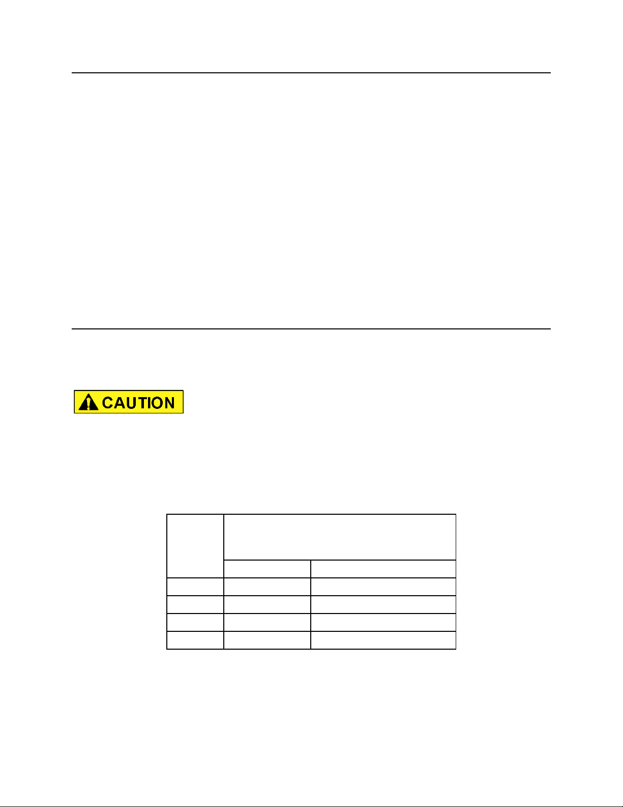
MODEL
RECOMMENDED EXCAVATOR
CLASS
3rd member mounting
US ton
(Metric ton)
DG-16
11 – 17.5
(10 - 16)
DG-20
15 - 22
(14 - 20)
DG-30
20 - 33
(18 - 30)
DG-40
27 - 44
(25 - 40)
NPK prides itself on the design and manufacture of high quality products. This tradition
of quality workmanship and materials continues in our DEMOLITION GRABS. Many
years of productive service can be realized with proper operation and care of the
DEMOLITION GRAB.
The purpose of this manual is to provide you with the information and instructions
required to properly operate and maintain the DEMOLITION GRAB. This will result in
maximum DEMOLITION GRAB reliability and productivity.
Read this manual thoroughly before attempting to operate, remove, disassemble,
repair or troubleshoot the DEMOLITION GRAB or any of its components.
Follow all the safety precautions contained in this manual. Failure to do so, can
result in death, personal injury, injury to others, and property damage.
EXCAVATOR COMPATIBILITY
These excavator weight ranges are intended as a guideline only. Other factors, such as
stick length, counterweights, undercarriage, etc., must be taken into consideration.
Mounting a DEMOLITION GRAB that is too heavy for the excavator can be dangerous
and damage the machine. Verify excavator stability with the DEMOLITION GRAB
before transport or operation.
Mounting a DEMOLITION GRAB that is too small for the excavator can damage the
DEMOLITION GRAB and void Warranties. Please consult NPK Engineering for specific
detailed information.
7
Page 9

SERIAL NUMBER LOCATION
DG16, DG20, DG30, DG40
sn2 – serial number tag
8
Page 10
SPECIFICATIONS
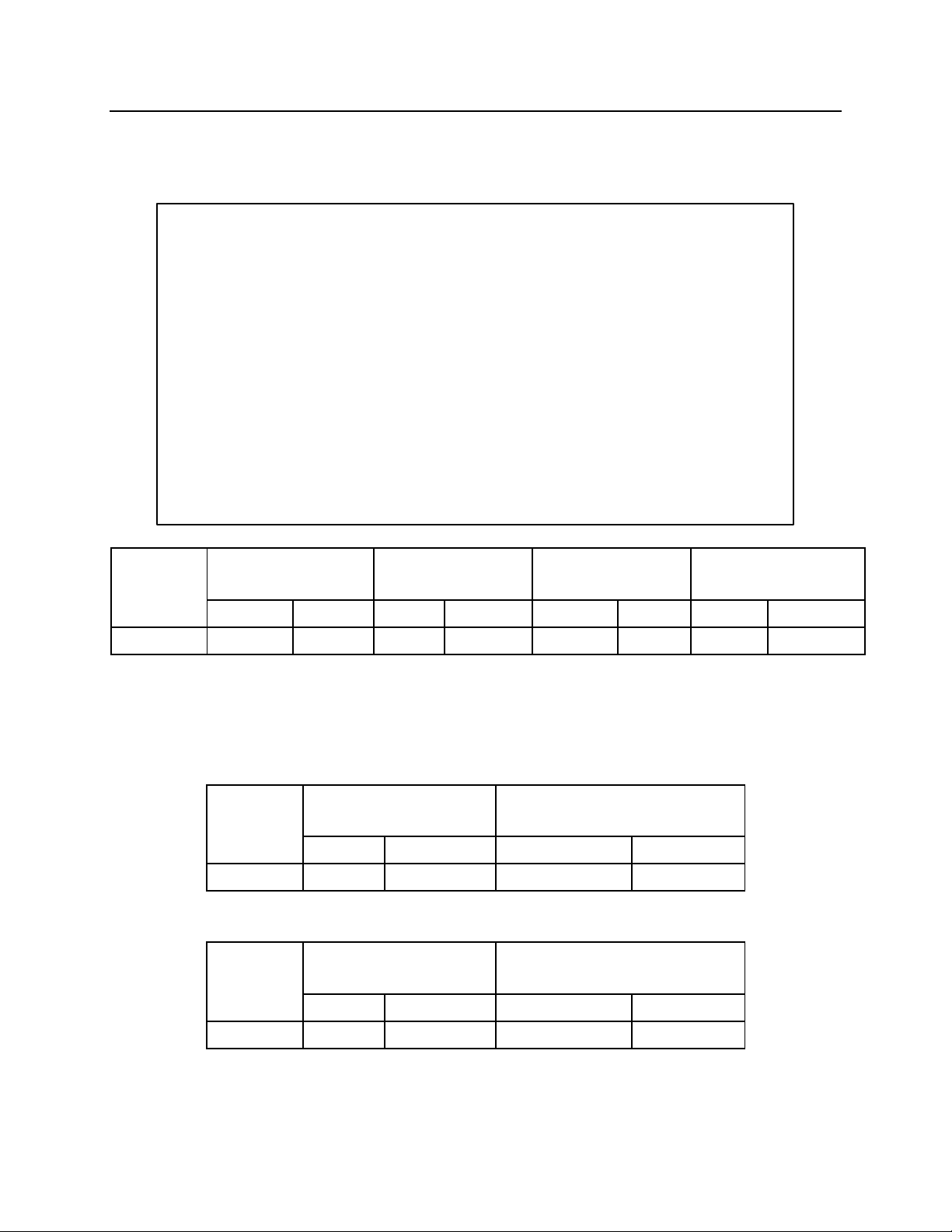
MODEL
WEIGHT
CLOSING
CAPACITY
MAXIMUM
FORCE
(volume)
HOIST LOAD
lbs.
(kg)
ton
(kN)
cu. yd.
(liter)
lbs.
(kg)
DG16
1,895
(860)
4.8
(48)
.55
(425)
7,716
(3,500)
MODEL
OIL FLOW
PRESSURE
MAIN JAWS
MAIN JAWS
gpm
(lpm)
psi
(bar)
DG16
16 - 26
(60 - 100)
3,625 - 5,100
(250 - 350)
MODEL
OIL FLOW
PRESSURE
ROTATION
ROTATION
gpm
(lpm)
psi
(bar)
DG16
5 - 8
(20 - 30)
1,450 - 2,030
(100 - 140)
DG16
ROTATION:
Rotation is 360°
NOTE: Specifications subject to change without notice.
9
Page 11
SPECIFICATIONS
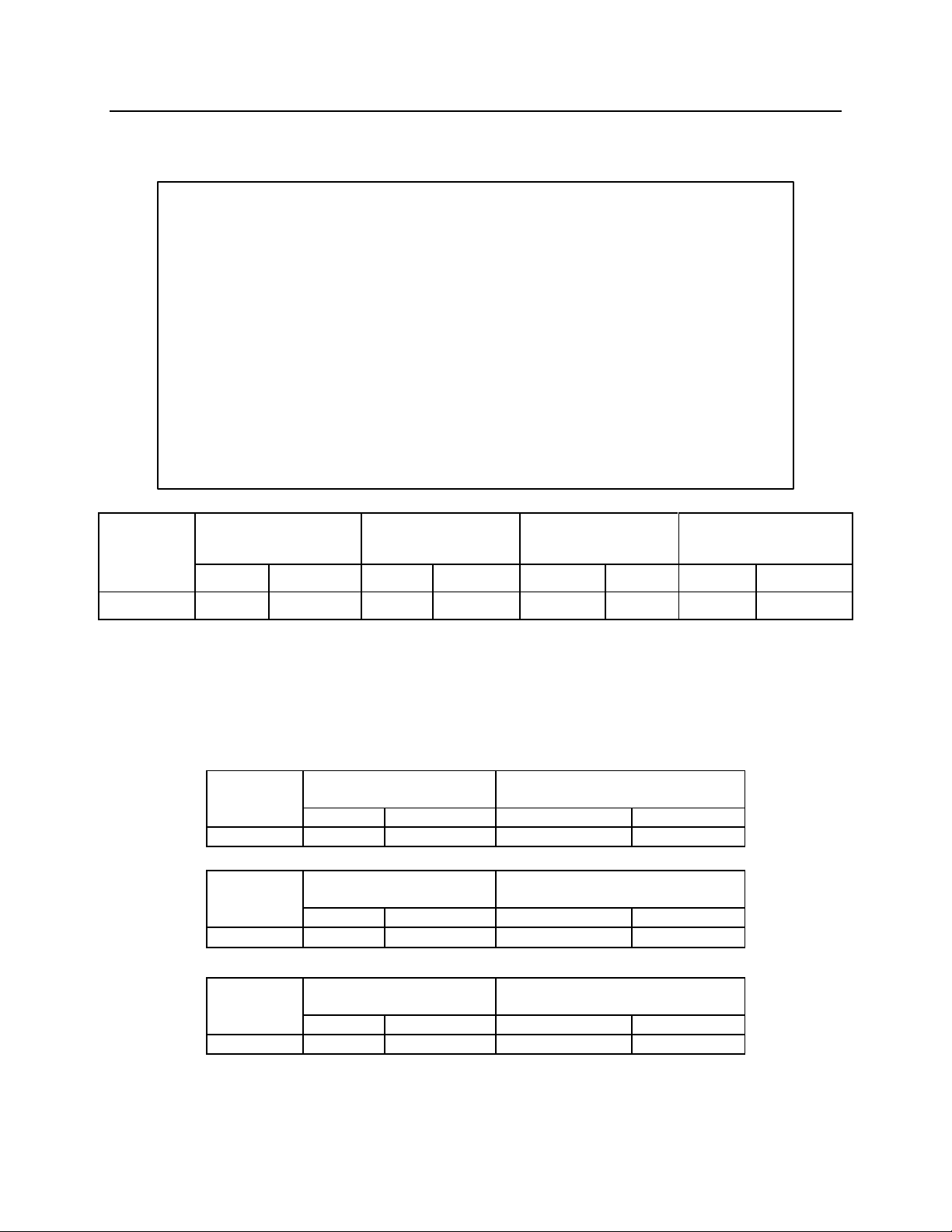
MODEL
WEIGHT
CLOSING
CAPACITY
MAXIMUM
FORCE
(volume)
HOIST LOAD
lbs.
(kg)
ton
(kN)
cu. yd.
(liter)
lbs.
(kg)
DG20
2,535
(1,150)
5.2
(52)
.65
(500)
9,920
(4,500)
MODEL
OIL FLOW
PRESSURE
MAIN JAWS
MAIN JAWS
gpm
(lpm)
psi
(bar)
DG-20
16 - 26
(60 - 100)
3,625 - 5,100
(250 - 350)
MODEL
OIL FLOW
PRESSURE
ROTATION
ROTATION
gpm
(lpm)
psi
(bar)
DG-20
9 - 16
(35 - 60)
1,450 - 2,030
(100 - 140)
OPTIONAL SINGLE MOTOR
MODEL
OIL FLOW
PRESSURE
ROTATION
ROTATION
gpm
(lpm)
psi
(bar)
DG-20
5 - 8
(20 - 30)
1,450 - 2,030
(100 - 140)
DG20
ROTATION:
Rotation is 360°
NOTE: Specifications subject to change without notice.
10
Page 12
SPECIFICATIONS
MODEL
WEIGHT
CLOSING
CAPACITY
MAXIMUM
FORCE
(volume)
HOIST LOAD
lbs.
(kg)
ton
(kN)
cu. yd.
(liter)
lbs.
(kg)
DG30
3,858
(1,750)
7.2
(72)
1.05
(800)
12,125
(5,500)
MODEL
OIL FLOW
PRESSURE
MAIN JAWS
MAIN JAWS
gpm
(lpm)
psi
(bar)
DG-30
21 - 32
(80 - 120)
3,625 - 5,100
(250 - 350)
MODEL
OIL FLOW
PRESSURE
ROTATION
ROTATION
gpm
(lpm)
psi
(bar)
DG-30
9 - 16
(35 - 60)
1,450 - 2,030
(100 - 140)
OPTIONAL SINGLE MOTOR
MODEL
OIL FLOW
PRESSURE
ROTATION
ROTATION
gpm
(lpm)
psi
(bar)
DG-30
5 - 8
(20 - 30)
1,450 - 2,030
(100 - 140)
DG30
ROTATION:
Rotation is 360°
NOTE: Specifications subject to change without notice.
11
Page 13
SPECIFICATIONS
MODEL
WEIGHT
CLOSING
CAPACITY
MAXIMUM
FORCE
(volume)
HOIST LOAD
lbs.
(kg)
ton
(kN)
cu. yd.
(liter)
lbs.
(kg)
DG40
4,519
(2,050)
7.2
(72)
1.18
(900)
12,125
(5,500)
MODEL
OIL FLOW
PRESSURE
MAIN JAWS
MAIN JAWS
gpm
(lpm)
psi
(bar)
DG-40
21 - 32
(80 - 120)
3,625 - 5,100
(250 - 350)
MODEL
OIL FLOW
PRESSURE
ROTATION
ROTATION
gpm
(lpm)
psi
(bar)
DG-40
9 - 16
(35 - 60)
1,450 - 2,030
(100 - 140)
OPTIONAL SINGLE MOTOR
MODEL
OIL FLOW
PRESSURE
ROTATION
ROTATION
gpm
(lpm)
psi
(bar)
DG-40
5 - 8
(20 - 30)
1,450 - 2,030
(100 - 140)
DG40
ROTATION:
Rotation is 360°
NOTE: Specifications subject to change without notice.
12
Page 14
HYDRAULIC INSTALLATION
NPK Hydraulic Installation Kits are available for virtually all compatible excavator
models. The kits include all parts and complete instructions for the hydraulic
installation, including valving and/or controls, hoses and fittings, boom and stick tubing,
and clamps.
See your NPK dealer for details or call NPK at 1-800-225-4379.
HYDRAULIC LINES
Typically, the pressure line to close is arranged on the left side of the boom and the
open line is on the right side.
SHUT-OFF VALVES
Most NPK Hydraulic Installation Kits use two shut-off valves (k4) on the dipper stick (k1)
of the carrier. These valves control the hydraulic oil going to the close side (m3) and
the open side (m4) from the Demo Grab attachment.
Pressure test ports (k8) are located in the shut-off valves. Each shut-off valve has an
“ON” (k5) and an “OFF” (k6) position.
13
Page 15
HYDRAULIC INSTALLATION
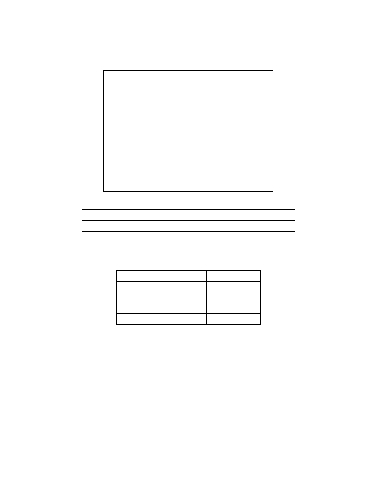
m3
HOSE: arm close
m4
HOSE: arm open
m39a
ROTATION HOSE: for clockwise movement
m39b
ROTATION HOSE: for counter-clockwise movement
MODEL
OPEN/CLOSE
ROTATION
DG16
12 JIC
8 JIC
DG20
12 JIC
8 JIC
DG30
12 JIC
8 JIC
DG40
12 JIC
8 JIC
PORT CONNECTION DIAGRAM
14
Page 16
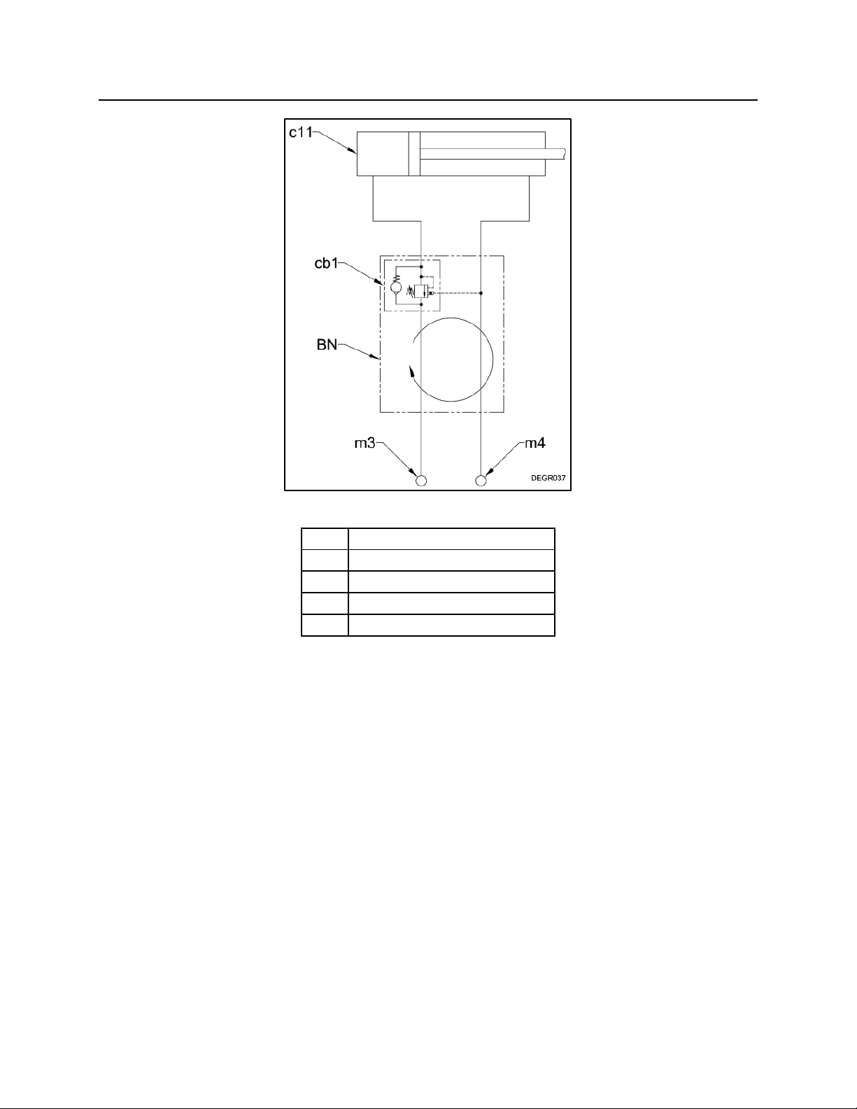
DEMOLITION GRAB HYDRAULIC CIRCUITS
BN
ROTARY JOINT ASSEMBLY
c11
CYLINDER
cb1
COUNTERBALANCE VALVE
m3
ARM CLOSE PORT
m4
ARM OPEN PORT
CYLINDER HYDRAULIC CIRCUIT
15
Page 17
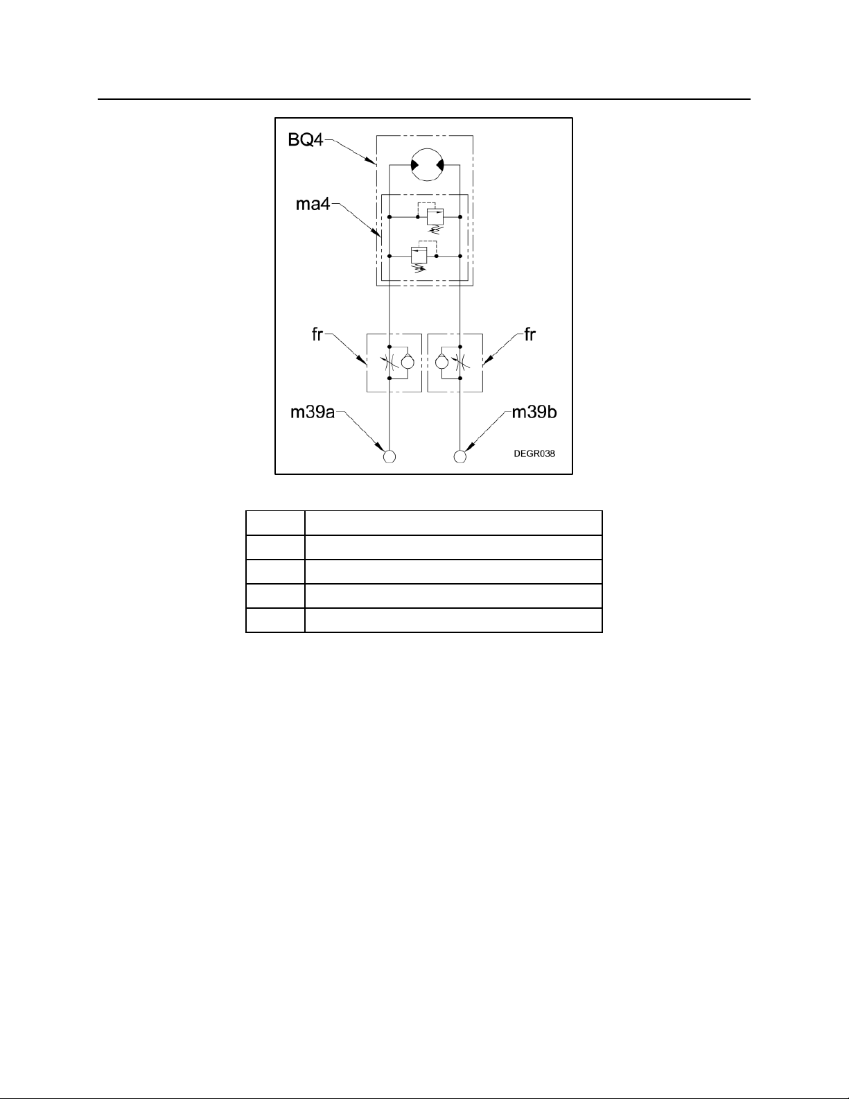
DEMOLITION GRAB HYDRAULIC CIRCUITS
BQ4
HYDRAULIC MOTOR
fr
FLOW REGULATOR
ma4
CROSS PORT RELIEF
m39a
CLOCKWISE ROTATION PORT
m39b
COUNTER-CLOCKWISE ROTATION PORT
SINGLE MOTOR HYDRAULIC CIRCUIT
16
Page 18
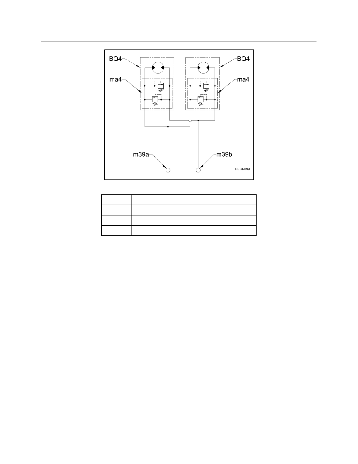
DEMOLITION GRAB HYDRAULIC CIRCUITS
BQ4
HYDRAULIC MOTOR
ma4
CROSS PORT RELIEF
m39a
CLOCKWISE ROTATION PORT
m39b
COUNTER-CLOCKWISE ROTATION PORT
DUAL MOTOR HYDRAULIC CIRCUIT
17
Page 19
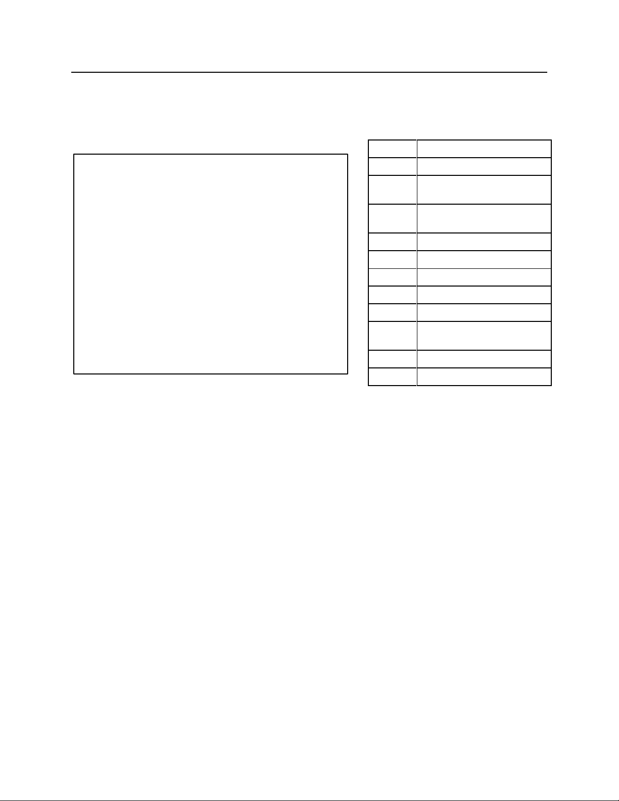
MOUNTING INSTALLATION
m1
STICK PIN (optional)
m2
LINK PIN (optional)
m3
WHIP HOSE - CLOSE
(optional)
m4
WHIP HOSE - OPEN
(optional)
m7
TOP BRACKET
m11
BRACKET BOLT
m12
HEX NUT
m13
WASHER
m27
SWIVEL TOP
m39
ROTATION HOSE
(optional)
m42
HEX NUT
m43
PIN BOLT
NPK Mounting Installation Kits include the parts required to adapt the NPK Demolition
Grab to the stick or arm of the excavator. The kits include all necessary stick and link
pins, bolts, etc.
18
Page 20
MOUNTING INSTALLATION
The hydraulic lines must be handled carefully to
prevent contamination from entering the
Demolition Grab or the carrier hydraulic system.
ATTENTION
MOUNTING TO THE EXCAVATOR
1. Position the Demolition Grab on wood blocks (t20) as shown.
2. Align the stick pin bore (m24). Install the stick pin (m1).
3. Align the link pin bore (m25). Install the link pin (m2).
4. Clean away any dirt found on the hose connections, connect the whip hoses (m3
and m4) and the rotation hoses (m39).
5. Open the shut off valves (k4).
6. Remove safety bar.
REMOVAL FROM THE CARRIER
1. Retract the cylinder to open jaws fully.
2. Position the Demolition Grab horizontal on wood blocks (t20), as shown above.
3. Install safety bar.
4. Close the shut-off valves.
5. Shut off engine and relieve all hydraulic pressure.
6. Disconnect the hydraulic hoses before setting the Demolition Grab down. Install
plugs in the hydraulic hoses and caps on the stick tubes to keep out contamination.
STORAGE OF DEMOLITION GRAB
1. Make sure the hydraulic hoses are plugged and stick tubes capped.
2. Grease all lubrication points, see page 27.
3. If stored outdoors, cover with waterproof tarp.
19
Page 21
OPERATING INSTRUCTIONS
Before operating the NPK Demolition Grab, be sure to read the safety information
and perform the daily and weekly maintenance as specified in this manual.
DO NOT OPERATE THE DEMOLITION GRAB WITHOUT DEMOLITION
GUARDS IN PLACE!
DO NOT LIFT OR LOAD BEYOND THE CAPACITY OF THE
DEMOLITION GRAB OR THE EXCAVATOR.
20
Page 22

OPERATING INSTRUCTIONS
USE THE DEMOLITION GRAB ONLY FOR THE APPLICATION FOR WHICH IT IS
INTENDED:
The NPK Demolition Grab is an attachment which is designed for grabbing and
moving of materials which are on a solid base, under water or in a construction
setting, but in such a way, that no danger is caused to the surroundings and
operators.
21
Page 23

ATTENTION
OPERATING INSTRUCTIONS
OPERATING TECHNIQUES AND PRECAUTIONS
Do not use the Demolition Grab with the excavator cylinders fully extended (96) or
retracted (97).
Do not strike the material with the Demolition Grab jaw set (DO1). Do not push, pull or
scrape material with the Demolition Grab.
22
Page 24
ATTENTION
OPERATING INSTRUCTIONS
OPERATING TECHNIQUES AND PRECAUTIONS
Do not pry, twist or pull with the excavator.
The excavator is used as a way of positioning the Demolition Grab and supplying
hydraulic power to the Demolition Grab.
Do not operate the Demolition Grab on an excavator with a combination Hydraulic
Hammer/Crusher hydraulic installation kit without first isolating line-mounted
accumulators (k23).
1. Shut-off valve (k4) must be in the off (k6) position for use with the Demolition Grab.
2. Return line from hammer/compactor (Demolition Grab open) (FT).
On some later NPK hydraulic kits, the lockout feature is done automatically through the
use of an accumulator isolation valve (k26). Consult with NPK at 1-800-225-4379 if you
are unsure of what your machine is equipped with.
23
Page 25

OPERATING INSTRUCTIONS
For most efficient operation, open the jaw only wide enough to grasp the material.
Grasp the material to be grabbed as deep into the throat of the Demolition Grab as
possible. Do not force the material into the jaws.
If you have any questions on operating the Demolition Grab, please contact your local
NPK dealer or call the NPK Service Department at 1-800-225-4379.
24
Page 26

GENERAL MAINTENANCE
REFER TO IMPORTANT SAFETY INFORMATION SECTION
DAILY INSPECTION AND MAINTENANCE
The functions that the Demolition Grab performs are demanding jobs in tough
environments. Therefore, it is extremely important that the following maintenance and
inspection procedures be performed daily.
Grease all lubrication points! Use moly EP2 or equivalent grease. Lubrication
points are at the following locations as shown on page 27.
Check for oil leaks at the Cylinder Piston Rod and all of the Demolition Grab’s hoses
and fittings.
Check all fasteners for looseness. Retighten if necessary.
Inspect all welds and repair as necessary.
Inspect the hydraulic hoses for wear, damage or oil leakage.
25
Page 27
GENERAL MAINTENANCE
22 – Direction of Grinding
23 – Direction of Principle Stress
ARM MAINTENANCE
Check for wear of the replaceable cutters (dg3 and dg4). If the cutters no longer touch,
they must be replaced. The diagram below shows new (CY) and worn (CZ) cutters.
FRAME MAINTENANCE
Inspect frame welds for cracks or other deformities.
FRAME CRACK REPAIR
1. Drill 3/16” (5 mm) hole through the plate at the end of the crack to prevent further
crack propagation.
2. Grind out the crack and weld as shown. Use AWS E7018 or equivalent welding rod.
3a. For plate sizes up to 3/4” (20 mm) thick, use the weld joint shown below:
3b. For plate sizes over 3/4" (20 mm) thick, use weld joint shown below:
4. Grind weld flush as shown:
26
Page 28

GENERAL MAINTENANCE
LUBRICATION POINTS
GR1 Cylinder rod pin: one lubrication point located at drive arm attachment
end. 10 strokes from grease gun every 4 hours.
GR3 Jaw pivot pin: one lubrication point for each pin, located on main frame.
15 strokes from grease gun per fitting every 4 hours.
GR4 Slewing ring/pinion teeth: three lubrication points on outside diameter of
the slewing ring. 5 strokes from grease gun per fitting once per shift.
GR5 Motor pinion: one lubrication point. 5 strokes from grease gun once per
shift.
GR6 Cylinder base end pin: one lubrication point located at arm attachment
end. 10 strokes from grease gun every 4 hours.
GR9 Link plate pivot pins: one lubrication point each end per link. 10 strokes
from grease gun every 4 hours.
27
Page 29

SLEWING RING INSPECTION AND MAINTENANCE
MODEL
ALL
MODEL
ALL
NEW
MAXIMUM
inch (mm)
<.010 (0.25)
MAXIMUM
ALLOWABLE
WEAR
inch (mm)
0.138 (3.50)
MEASURING MAXIMUM AXIAL MOVEMENT
1. While the unit is attached to the excavator, position the Demolition Grab in the
vertical position.
2. Using a dial indicator (t40), lock the base of the dial indicator onto the lower frame of
the Demolition Grab. Indicate the other end of the dial onto the top bracket face as
shown. Using the excavator, slightly rock the Demolition Grab back and forth using
slight stick movement. Note the movement shown by the dial. Take this reading
(d59) in four places. If your readings are greater than shown, please contact the
NPK Service Department at 800-225-4379.
28
Page 30
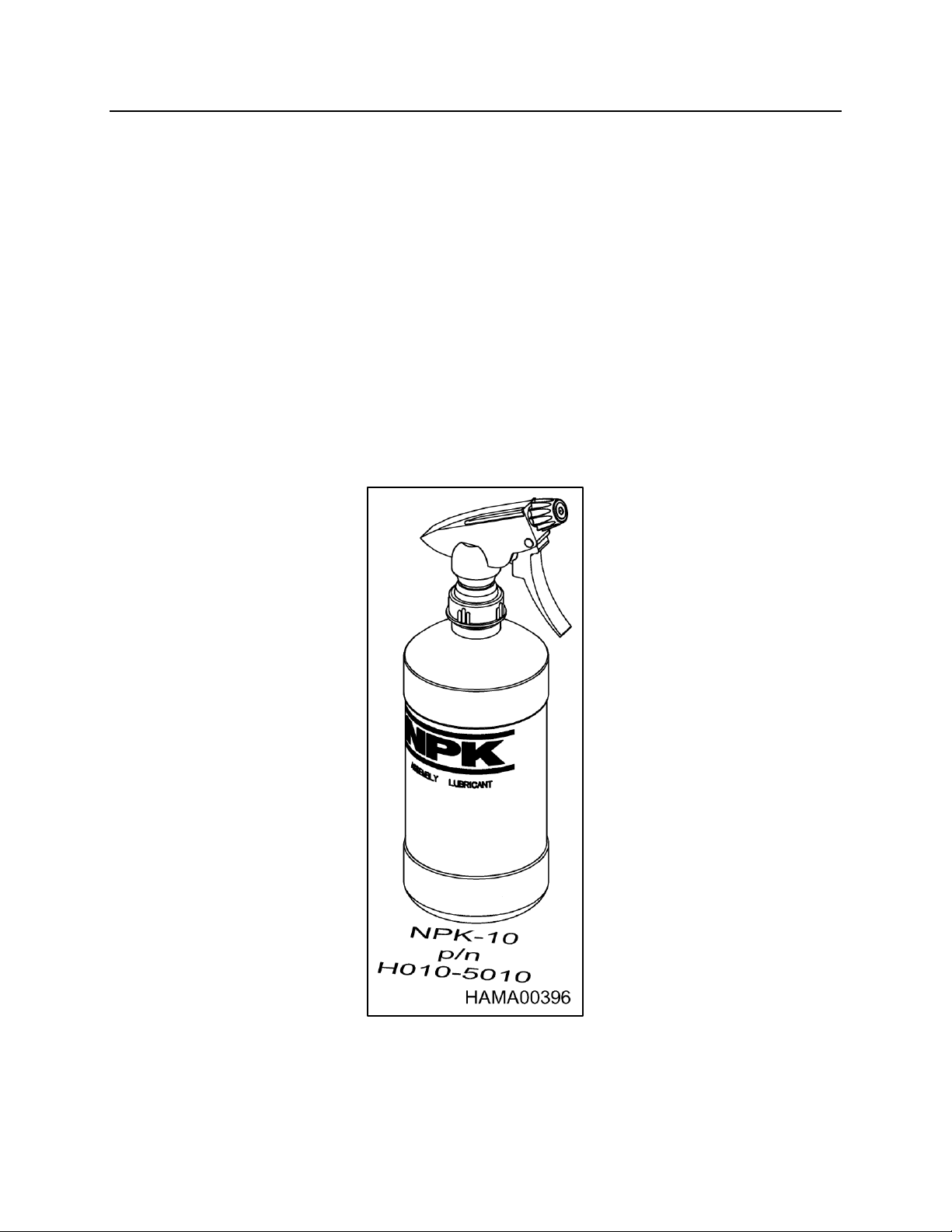
NPK ASSEMBLY LUBRICANT
NPK ASSEMBLY LUBRICANT is specially formulated to provide quick, positive
lubrication. Oil rich ingredients, plus a free-flowing light lithium grease, offer top
lubrication, as well as long lasting protection against rust and corrosion. NPK
ASSEMBLY LUBRICANT even “creeps” into remote, normally inaccessible areas to
lubricate and safeguard interior metal surfaces. NPK ASSEMBLY LUBRICANT is ideal
for use on all metal-to-metal surfaces.
DIRECTIONS FOR USE
1. Wipe off exposed surfaces.
2. Shake vigorously to thoroughly mix contents.
3. Spray liberally on areas requiring lubrication.
NPK ASSEMBLY LUBRICANT contains NPK-10 Metal Treatment and is ideal for use
in the assembly of all NPK products. NPK ASSEMBLY LUBRICANT comes in a 16
ounce bottle with sprayer and can be ordered using part number H010-5010.
29
Page 31

ROTARY JOINT MAINTENANCE
HYDRAULIC ROTARY JOINT
ASSEMBLY
The hydraulic rotary joint assembly (BN) is mounted inside
the swivel top assembly (m27) which is under the top
bracket (m7) that pins to the carrier and is bolted to the
slewing ring (BT) which rotates the Demolition Grab’s
main frame. Hydraulic oil for both open and close
operations passes through it. The rotary joint assembly
consists of two main parts, the “Spindle Case”, which
contains the oil seals and the “Spindle”, which rotates the
Demolition Grab’s main frame.
LEAKAGE OF THE SEALS
External leakage or internal (bypassing) of hydraulic oil
will require the replacement of the seals in the rotary joint
assembly. For external leakage, please review the seal replacement procedure in the
next section. If internal leakage is suspected, please proceed to the “TESTING THE
ROTARY JOINT SEALS FOR INTERNAL LEAKAGE” section.
TESTING THE ROTARY JOINT SEALS FOR INTERNAL
LEAKAGE
If internal seal leakage is suspected, before disassembling the rotary joint assembly
(BN), the counterbalance valve cartridge (cb1) pressure setting should be checked.
Internal leakage will most likely prevent the unit from reaching relief pressure in the
close function. The relief cartridge is located below the rotary joint in a block that the
hose connections to the cylinder are located. Access to the relief valve cartridge is
through the cover plates of the swivel top assembly.
NOTE: Before attempting to adjust the relief setting, please check that the relief valve
cartridge has not loosened in the block.
30
Page 32
ROTARY JOINT MAINTENANCE
TESTING THE ROTARY JOINT SEALS FOR INTERNAL
LEAKAGE
PROCEDURE
Install a 0 – 5,000 psi gauge (g8f) in the NPK shut-off (k4) located on the stick of the
carrier. Close the arms and keep the function activated and read the pressure.
Compare the pressure reached with the specifications for your model Demolition Grab
(GZ). If the proper relief pressure cannot be reached, you must disassemble the rotary
joint to check for failed seals.
REPLACEMENT OF THE SEALS IN THE ROTARY JOINT
The arms (dg1 and dg2) of the Demolition Grab should be opened and safety bar (t79)
installed during repair. Close the NPK shut-off valves on the stick of the carrier.
31
Page 33

ROTARY JOINT MAINTENANCE
REPLACEMENT OF THE SEALS IN THE ROTARY JOINT
Step 1
Remove the top bracket from the swivel flat top assembly. Remove the joint fitting
adapter fittings (m44) from the spindle case manifold blocks. Remove the hoses (AO)
from the spindle base manifold. Remove the bolt (AF) and spacer (ZZ) from the spindle
base manifold. Remove the four mounting bolts (AF1) from the spindle case. Pull the
rotary joint assembly (BN) from the swivel flat top assembly.
Figure 1
Step 2
Remove the three flat head socket screws (AF9). Remove the top plate (CH) and o-ring
(RR) from the spindle case (BZ). Remove the spindle case and o-ring from the spindle
(CA).
Figure 2
32
Page 34

ROTARY JOINT MAINTENANCE
REPLACEMENT OF THE SEALS IN THE ROTARY JOINT
Step 3
Inspection:
Visually inspect the sealing surfaces of the spindle (CA) for damage, which may hamper
the ability of the main seals to seal. Polishing the surfaces (120) may clean up light
scratching. Heavy scratching or galling may indicate rotator bearing play.
Figure 3
Step 4
Seal removal and replacement:
Sealing is accomplished by the use of main seals, which ride against the “Spindle” and
glide bearings. Remove the main seals and glide rings with a seal pick (note the proper
placement of main seals and glide bearings). Check the grooves (118) in the “Spindle
Case” (BZ) for burrs or scoring damage. Light grinding or polishing may be required.
Figure 4
33
Page 35

ROTARY JOINT MAINTENANCE
REPLACEMENT OF THE SEALS IN THE ROTARY JOINT
Step 5
Rotary joint reassembly:
Lubricate the main seals (dg8), glide bearings (dg7) and o-rings (RR) with grease or
NPK Assembly Lubricant. Install the main seals into the “Spindle Case” (BZ) first. Then
install the first o-ring and glide bearing to the underside of the spindle case. Slide the
“Spindle Case” over “Spindle” (CA). Then install second glide bearing and o-ring.
Install the cover plate (CH) and three flat head socket screws (AF9). Make sure the
counterbalance valve cartridge (cb1) is tight.
Figure 5
34
Page 36

TROUBLESHOOTING
DETERMINE THE TYPE OF PROBLEM
Performance problems are classified as “LOSS OF POWER” OR “LOSS OF CYCLE
SPEED” (assuming the problem is not due to misapplication).
1. LOSS OF POWER
NPK attachment grabbing forces are determined by the operating pressure
settings.
2. LOSS OF CYCLE SPEED
NPK attachment cycle speed is determined by the hydraulic flow to the unit. The
hydraulic installation circuit must be set to provide the correct oil flow.
DETERMINE THE CAUSE OF THE PROBLEM
Technical problems are caused by either the NPK attachment or the hydraulic circuit
(carrier hydraulics or installation kit). Checking the hydraulic pressure and flow will
determine if the problem is in the Demo Grab or the carrier. If the pressures and flow
available to the Demo Grab are correct, the problem is in the Demo Grab.
GUIDE FOR LOSS OF POWER (relief valve checks)
Loss of power can be caused by a low carrier relief valve setting or a low Demo Grab
relief setting. Verify the correct relief valve settings of the carrier and the Demo Grab.
Refer to the “RELIEF VALVE CHECKING AND SETTING PROCEDURE” and the
troubleshooting chart.
MEASURING OPERATING PRESSURES
Tools and Equipment required:
Qty. 1 -Pressure gauge: 0 – 5,000 psi (0 – 350 bar), for arm close circuit.
Qty. 1 -Test port adapter: to fit #4 SAE female port in the NPK shut-off valve.
Qty. 1 -Test hose: rated for 5,000 psi (350 bar).
RELIEF VALVE CHECKING AND SETTING PROCEDURE
NPK Installation Kits provide shut-off valves (k4) with test ports (k8) in both arm open
(m4) and arm close (m3) hydraulic lines. Install pressure test hoses in both the arm
open and arm close test ports.
35
Page 37

TROUBLESHOOTING
RELIEF VALVE CHECKING AND SETTING PROCEDURE
A. THE CARRIER’S HYDRAULIC CIRCUIT RELIEF VALVE
Verify that the hydraulic circuit meets the Demo Grab’s (GZ) requirements; see
“SPECIFICATIONS”, pages 9 through 12.
1. Install a 0 – 5,000 psi (0 – 350 bar) pressure gauge (g8f) in the #4 SAE test port
(k8) on the arm close side and a 0 – 5,000 psi (0 – 350 bar) pressure gauge
(g8b) in the #4 SAE test port on the arm open side located in both shut off valves
(k4) at the end of the stick.
2. Turn the shut-off valves (k4) to the “OFF” position (k6).
3. Start the carrier. Set the throttle to the “FULL” position. Actuate the hydraulic
circuit to close the Demo Grab’s arms.
4. The pressure reading on the gauge should be a minimum of 500 psi (34 bar)
above the Demo Grab’s relief valve setting, see “SPECIFICATIONS”, pages 9
through 12. NOTE: If the carrier’s relief is not set at a minimum of 500 psi (34
bar) above the Demo Grab’s relief, reset or replace at this time.
36
Page 38

TROUBLESHOOTING
RELIEF VALVE CHECKING AND SETTING PROCEDURE
B. DEMO GRAB’S COUNTERBALANCE VALVE
After the carrier’s hydraulic circuit has been verified, check the Demo Grab’s
counterbalance valve setting.
1. With the 0 – 5,000 psi (0 – 350 bar) gauge in the arm close side and the 0 –
5,000 psi (0 - 350 bar) in the arm open side of the stick, turn the shut-off valves
(k4) to the “ON” position (k5).
2. Start the carrier. Set the throttle to the full position then close the arms
completely and hold for ten seconds. Check the psi (bar) reading on the gauge
and compare to the Demo Grab’s specified counterbalance valve setting. If the
reading is not per specification, see “SPECIFICATIONS”, pages 9 through 12
and reset the counterbalance valve cartridge. If you are unable to reset the
counterbalance, refer to the troubleshooting chart.
COUNTERBALANCE VALVE LOCATION
The counterbalance valve cartridge (cb1) is located in the manifold block, which is part
of the rotary joint assembly (BN). (See the unit’s parts breakdown for the location of the
rotary joint.)
37
Page 39
TROUBLESHOOTING
PROBLEM
CAUSE
CHECK
REMEDY
Operating pressure
is less than 3,625 psi
(250 bar).
Excavator hydraulic
circuit relief valve.
Measure the
excavator circuit
relief valve pressure
with the left hand
shut-off valve
closed.
Adjust or replace the
excavator circuit
relief valve.
Attachment relief
valves.
Measure the
attachment relief
valves with the shutoff valves open.
Replace the
attachment relief
valve.
Check the relief
valve cartridge for
tightness.
Tighten the relief
valve cartridge.
Check the relief
valve cartridge for
mis-adjustment.
Re-adjust the relief
cartridge.
Check the o-rings
and backup rings of
the relief valve
cartridge.
Replace the o-rings
and backup rings of
the relief valve
cartridge.
Check the seals
between the open
and close passages
of the swivel
manifold assembly.
Replace the seals in
the swivel manifold
assembly.
Check the land
areas for the seals in
the swivel manifold
assembly.
Repair the land
areas or replace the
spindle.
TROUBLESHOOTING CHART FOR LOW POWER
NOTE: If additional assistance is required, call the NPK Service Department at
1-800-225-4379.
38
Page 40
TROUBLESHOOTING
1. Install a pressure gauge in the shut-off valve of the close side (left) of the
hydraulic circuit.
2. Install; a flow meter (t36) between
the Demo Grab (GZ) close and
open lines as shown.
NOTE: Typically, the arm close line
(m3) is on the left (from the
operator’s) seat and arm open (m4)
is on the right.
3. To determine return line pressure
(pressure drop) open both shut-off
valves (k4) and energize the arm
close circuit. Measure the pressure
with the load valve (fm1) of the flow
meter in the full open position.
TROUBLESHOOTING FOR SLOW CYLINDER SPEED
The cycle times of the Demo Grab are controlled by the flow provided by the hydraulic
circuit of the carrier. The cycle times of the Demo Grab are a direct result of the
maximum published oil flow, see “SPECIFICATIONS”, pages 9 through 12.
NOTE: If the jaws will not open or close, be sure the right and left shut-off valves are
open.
CHECKING HYDRAULIC FLOW AT RATED PRESSURE
Tools and Equipment required:
Qty. 1 -Pressure gauge: 0 – 5,000 psi (0 – 350 bar), for arm close circuit.
Qty. 1 -Test port adapter: to fit #4 SAE female port in the NPK shut-off valve.
Qty. 1 -Test hose: rated for 5,000 psi (350 bar).
Qty. 1 -Hydraulic flow meter: pressure loading type, 0 – 100 gpm (0 – 380 lpm)
PROCEDURE FOR CHECKING HYDRAULIC FLOW AT RATED
PRESSURE
minimum capacity.
39
Page 41
TROUBLESHOOTING
4. To determine the available flow and relief valve setting of the carrier, follow the
following procedure.
a. Adjust the load valve on the flow meter to zero restriction. Start the
carrier. Set the throttle to the “FULL” position.
b. Energize the close hydraulic circuit. Adjust the flow meter load valve until
the system reaches about 1,000 psi (70 bar). Warm the hydraulic system
of the carrier to normal operating temperature.
c. With the engine at full throttle and the flow meter set at zero pressure,
energize the close circuit. Turn in the loading valve adjustment knob and
record pressure and flow at regular intervals on graph paper. Record
pressure on one axis of the graph and flow on the other. Increase
pressure until the relief valve setting of the carrier is reached. This is the
circuit flow chart.
fl
Hydraulic Flow
pr
Pressure (psi)
d. Then set the flow meter at 1,000 psi (70 bar) and check flow. See
“SPECIFICATIONS” pages 9 through 12, for the correct flow for your
Demo Grab. If the reading on the flow meter does not match the Demo
Grab specification, adjust the flow of the carrier.
e. If the cycle speed is still too slow, refer to the slow cylinder speed
troubleshooting chart on the next page.
PROCEDURE FOR CHECKING HYDRAULIC FLOW AT RATED
PRESSURE
40
Page 42
TROUBLESHOOTING
PROBLEM
CAUSE
CHECK
REMEDY
Slow cylinder speed.
Operating pressure
okay. 3,625 psi (250
bar) minimum.
Carrier flow setting is
low.
Check flow output of
attachment hydraulic
circuit at 1000 psi
(69 bar).
Adjust control valve
flow adjustment of
carrier
Repair or replace the
carrier's pump
Check attachment
cylinder packing.
Replace if required.
Slow cylinder speed.
Operating pressure
not okay. Less than
3,625psi (250 bar)
Carrier relief set too
low. Set below 3,800
psi (262 bar).
Measure the
excavator circuit
relief valve pressure
with the shut-off
valve closed.
Adjust or replace the
carrier's circuit relief
valve.
Attachment
counterbalance
valve cartridge.
Check the
counterbalance
valve cartridge for
tightness
Tighten the
counterbalance
valve cartridge.
Check the o-rings
and backup rings of
the counterbalance
valve cartridge.
Replace the o-rings
and backup rings of
the counterbalance
valve cartridge.
TROUBLESHOOTING CHART FOR SLOW CYLINDER SPEED
NOTE: If additional assistance is required, call the NPK Service Department at 1-800-
225-4379.
JAW DRIFT
1. Some drift may be experienced depending on the Demo Grab’s position.
2. Acceptable drift may occur over a number of minutes.
3. Rapid drift may indicate a problem with the Demo Grab’s cylinder, rotary joint
assembly or the carrier’s hydraulic circuit.
TO DETERMINE IF THE JAW DRIFT IS OCCURING FROM A
BAD CYLINDER OR THE CARRIER
1. Remove the hoses from the joint fittings on the outside of the Demo Grab’s frame
and close the shut-off valves on the carrier.
2. Cap the joint fittings (#12 JIC).
If the jaw drifts, the problem is coming from the Demo Grab’s cylinder or rotary joint
assembly. If no drift occurs, the problem is in the carrier’s main control valve. Drift
due to the carrier’s main control valve internal leakage, may be inherent to the
carrier and may not be solvable.
41
Page 43
TROUBLESHOOTING
MODEL
OIL FLOW
PRESSURE
ROTATION
ROTATION
gpm
(lpm)
psi
(bar)
DG16
5 - 8
(20 - 30)
1,450 - 2,030
(100 - 140)
DG20
9 - 16
(35 - 60)
1,450 - 2,030
(100 - 140)
DG30
9 - 16
(35 - 60)
1,450 - 2,030
(100 - 140)
DG40
9 - 16
(35 - 60)
1,450 - 2,030
(100 - 140)
TROUBLESHOOTING FOR SLOW ROTATION SPEED
ROTATION
The rotation speed is a direct result of the amount of flow (gpm/lpm) supplied by the
rotation circuit of the carrier or NPK hydraulic kit. The chart on the following page lists
the approximate flow required.
The relief listed on the chart is only necessary to protect the rotation supply
componentry.
Adjust the rotation flow so that it is within the guidelines shown for the model being
tested.
Flows are checked at a normal operating pressure of 1,000 psi (70 bar). Cross port
relief valves rated at 2,500 psi (172 bar) are included in the hydraulic motor.
Excessive rotation speed will result in damage to the hydraulic motor, gearbox, or
bearing.
MEASURING ROTATION PRESSURES
Tools and Equipment Required
Qty. 1 -Pressure gauge: 0 – 3,000 psi (0 – 210 bar)
Qty. 1 -Gauge adapter fitting: 1/4” npt female x #6 JIC male
(NPK part number K023-6690)
Qty. 2 -Swivel run tee fittings: #8 JIC
Qty. 2 -Test hoses: rated for 3,000 psi (210 bar); #8 JIC female swivel one end and #6
JIC female swivel the other end.
42
Page 44
TROUBLESHOOTING
PROBLEM
CAUSE
CHECK
REMEDY
Unit will not rotate
Low or no flow.
Check hydraulic
flow. Reference
hydraulic flow chart
above.
Adjust the carrier's
flow to the
attachment.
Pressure setting of
cross port relief
valves (ma4).
Check cross port
relief valve settings.
See procedure
above.
Adjust the cross port
relief valves on the
rotation holding
valve.
Replace cross port
relief valves.
Broken pinion gear
or hydraulic motor
shaft.
Check pinion gear
and hydraulic motor
shaft.
Replace hydraulic
motor or pinion gear.
Unit will not hold
position.
Pressure setting of
cross port relief
valves.
Check cross port
relief valve settings.
See procedure
above.
Adjust the cross port
relief valves on the
rotation holding
valve.
Replace cross port
relief valves.
Broken pinion gear
or hydraulic motor
shaft.
Check pinion gear
and hydraulic motor
shaft.
Replace hydraulic
motor or pinion gear.
TROUBLESHOOTING FOR SLOW ROTATION SPEED
ROTATION PRESSURE CHECKING PROCEDURE
1. Install gauges in the rotation circuit lines.
2. Position the Demo Grab so that it will not rotate.
3. Attempt to rotate the unit in both directions. Each gauge should read 2,000 psi
(138 bar).
TROUBLESHOOTING CHART FOR ROTATION
43
Page 45

TROUBLESHOOTING
ADJUSTMENT OF ROTATION SPEED
DG16 UNITS AND DG20, DG30 AND DG40 UNITS WITH THE SINGLE MOTOR
OPTION
The rotation speed can be adjusted clockwise and counterclockwise independently from
each other.
PROCEDURE
1. Remove both covers (s9) from the side of the swivel top (m27).
2. When the covers are removed, two flow regulators (fr) will be visible.
3. These regulators are locked with a (3/32”) locking screw (c6). The screw has to be
loosened before the flow regulators can be adjusted.
4. By turning the adjustment knobs, you can either slow down or accelerate the rotation
speed.
NOTE: Be sure to tighten the locking screw when adjustment of the rotation speed
is completed.
44
Page 46
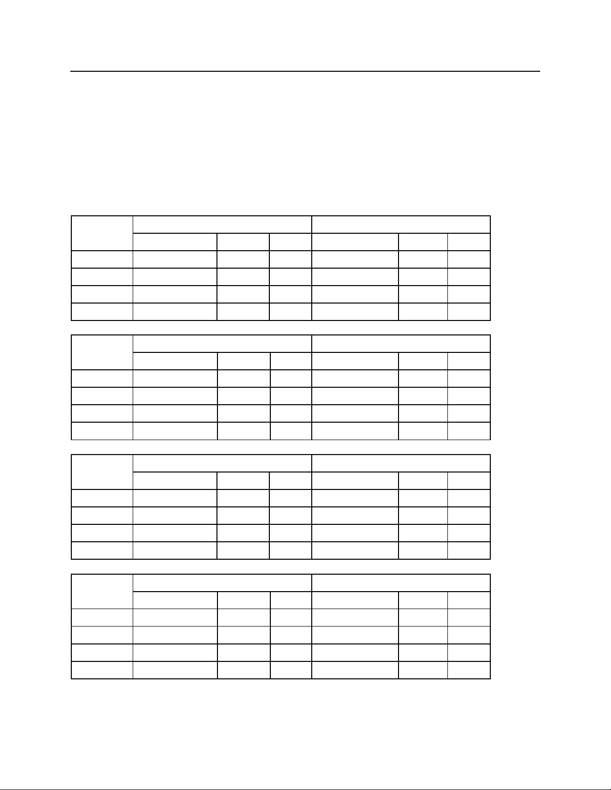
FASTENER TORQUE CHART
MODEL
CUTTER - FHCS
SWIVEL SUPPORT - HHCS
PART NO.
ft. lbs.
(Nm)
PART NO.
ft. lbs
(Nm)
DG16
97600033
290
(390)
71012045
65
(87)
DG20
97600033
290
(390)
71012045
65
(87)
DG30
97600001
290
(390)
71012045
65
(87)
DG40
97600001
290
(390)
71012045
65
(87)
MODEL
MOTOR MOUNTING - SHCS
SWIVEL MANIFOLD - SHCS
PART NO.
ft. lbs.
(Nm)
PART NO.
ft. lbs
(Nm)
DG16
74012060
65
(87)
74012040
65
(87)
DG20
74012060
65
(87)
74012040
65
(87)
DG30
74012060
65
(87)
74012040
65
(87)
DG40
74012060
65
(87)
74012040
65
(87)
MODEL
SAFETY BAR - HHCS
SUPPORT BRACKET - HHCS
PART NO.
ft. lbs.
(Nm)
PART NO.
ft. lbs
(Nm)
DG16
71020040
290
(390)
71012020
65
(87)
DG20
71020040
290
(390)
71012020
65
(87)
DG30
71020040
290
(390)
71012020
65
(87)
DG40
71020040
290
(390)
71012020
65
(87)
MODEL
TOP COVER - HHCS
COVER PLATES - HHCS
PART NO.
ft. lbs.
(Nm)
PART NO.
ft. lbs
(Nm)
DG16
71008020
19
(25)
71010020
37
(50)
DG20
71008020
19
(25)
71010020
37
(50)
DG30
71008020
19
(25)
71010020
37
(50)
DG40
71008020
19
(25)
71010020
37
(50)
These torque charts are to be used with the specific Demolition Grab Parts Manual for
the unit being repaired.
All fasteners will require lube or medium strength thread adhesive. Bolts must have
their threads wire brushed, or cleaned with a thread die; then cleaned with solvent; then
cleaned with compressed air. Threaded holes must be cleaned with a tap; then cleaned
with solvent; then cleaned with compressed air.
Do not use anti-seize compound on any fasteners, unless otherwise noted.
45
Page 47
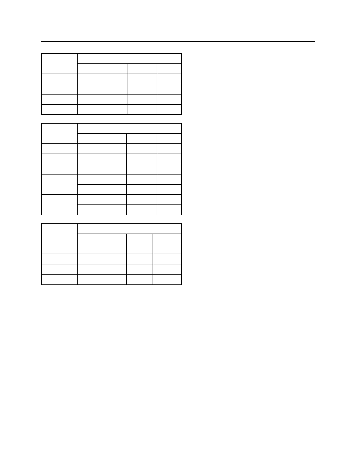
FASTENER TORQUE CHART
MODEL
PIN LOCK PLATE - SHCS
PART NO.
ft. lbs
(Nm)
DG16
74012025
65
(87)
DG20
74012025
65
(87)
DG30
74012025
65
(87)
DG40
74012025
65
(87)
MODEL
SLEWING RING - SHCS
PART NO.
ft. lbs.
(Nm)
DG16
74016075
225
(300)
DG20
74016075
225
(300)
74016070
225
(300)
DG30
74016080
225
(300)
74016090
225
(300)
DG40
74016080
225
(300)
74016090
225
(300)
MODEL
TOP BRACKET - HHCS
BOLT DIA.
ft. lbs
(Nm)
DG16
1"
750
(1015)
DG20
1"
750
(1015)
DG30
1-1/4"
1500
(2030)
DG40
1-1/4"
1500
(2030)
46
Page 48
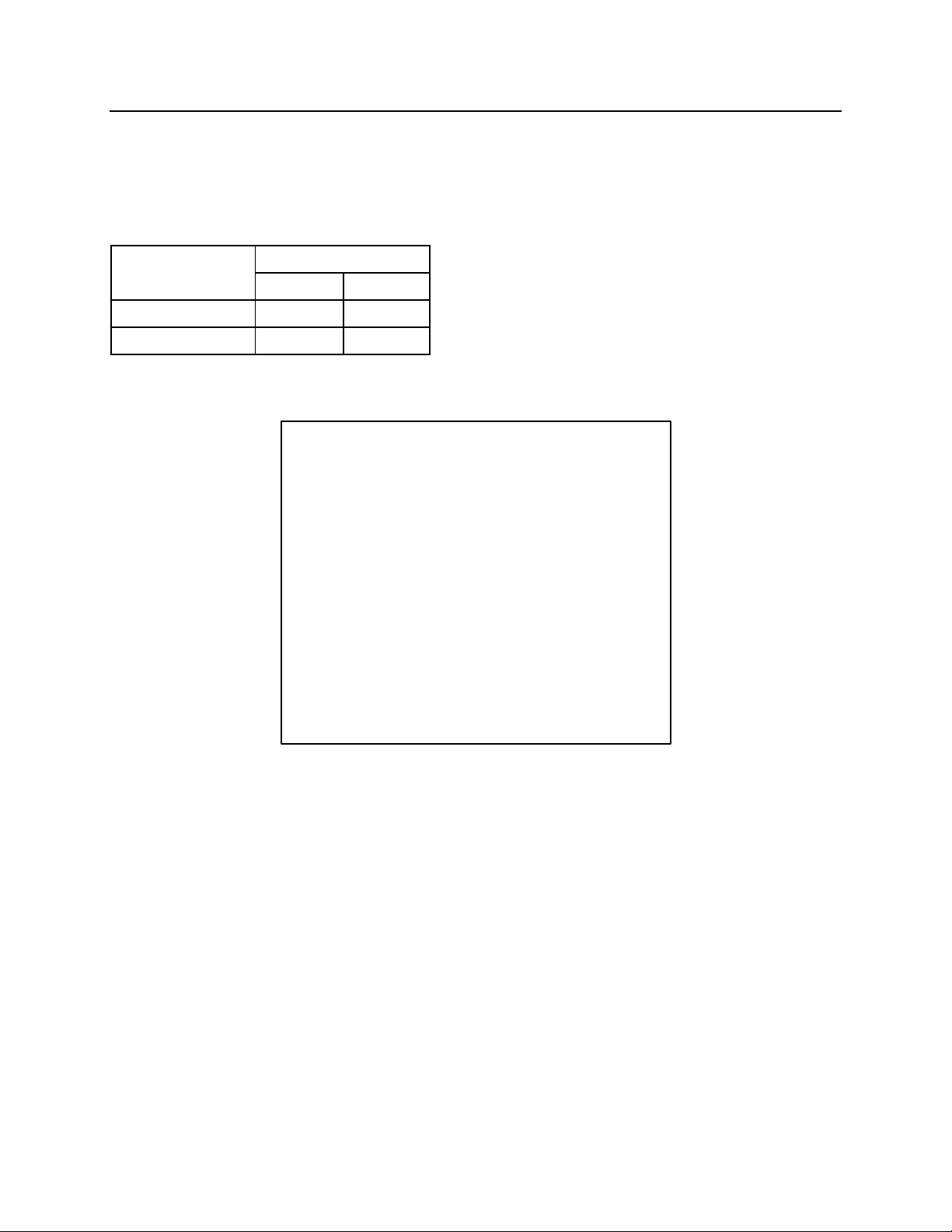
CYLINDER TORQUE SPECIFICATIONS
TORQUE
ft. lbs.
(Nm)
PISTON (c2)
1106
(1500)
ROD NUT (c1)
29.5
(40)
ROD NUT AND PISTON TORQUES
The torques listed below, are for the rod nut (c1) and piston (c2) used in the cylinder
assembly for the NPK Demolition Grab. When assembling during rebuild, it is al so
recommended that thread adhesive is used to ensure complete clamping.
Apply a small amount of thread adhesive to the set screw (c6) before installing.
47
Page 49
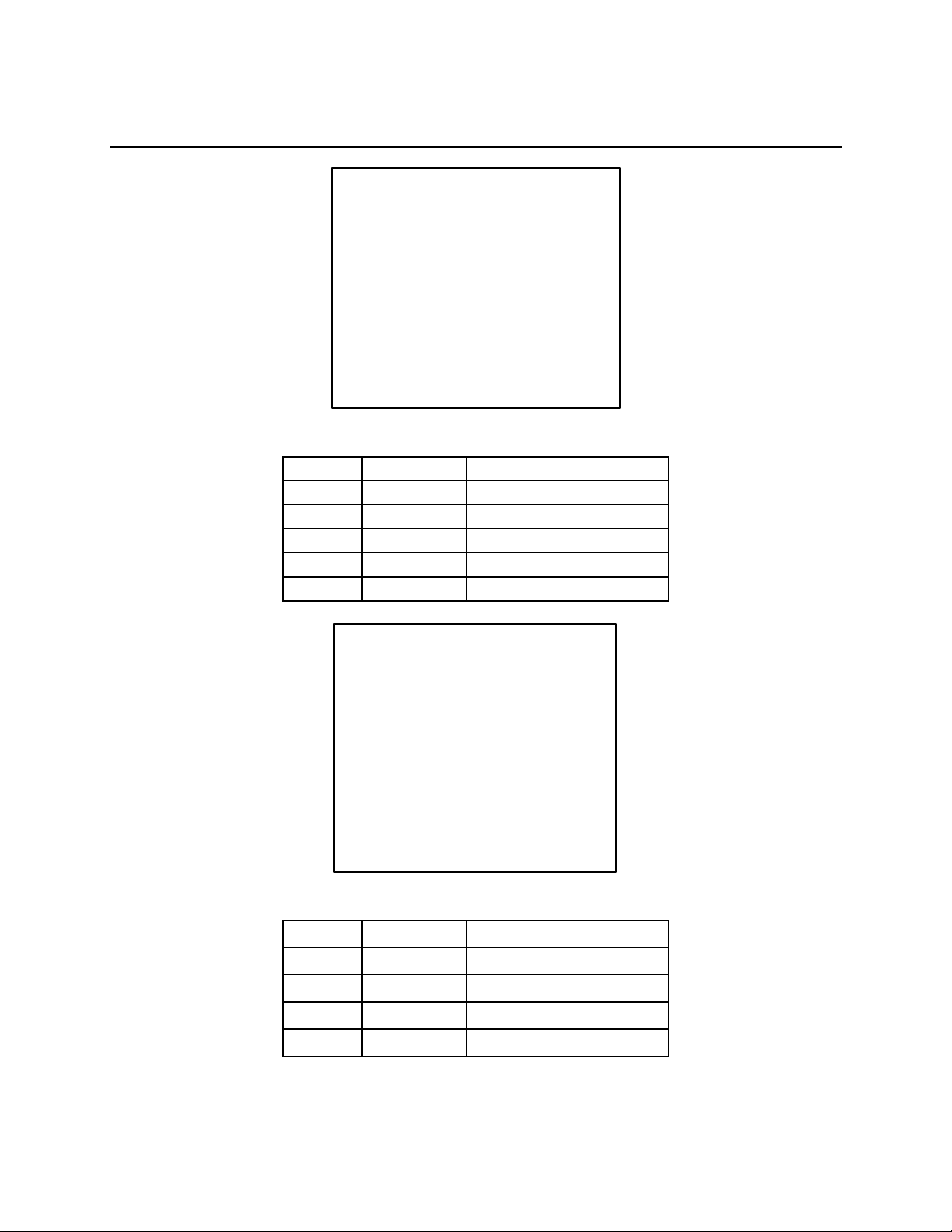
CONVERT FROM DUAL MOTOR TO SINGLE
AO
98500849
HOSE ASSEMBLY
BQ4
9850201
HYDRAULIC MOTOR
BR
98600640
PINION GEAR
DE
98601199
MOTOR PLATE
f3
98500155
TEE
g24
97600055
SWIVEL ELBOW
EC
98601233
COVER
f1
97600043
ADAPTOR FITTING
f4
97600046
90° ADAPTOR
f5
97600044
ADAPTOR FITTING
fr
98500241
FLOW VALVE
MOTOR (DG20, DG30, DG40)
PARTS TO REMOVE
PARTS TO ADD
48
Page 50
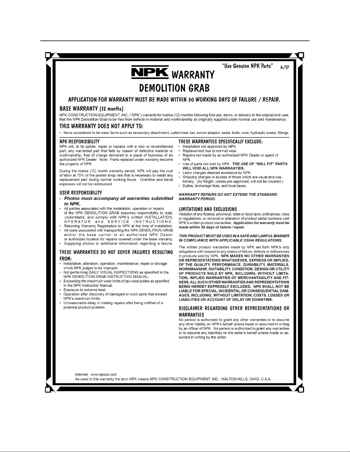
WARRANTY STATEMENTS
49
Page 51
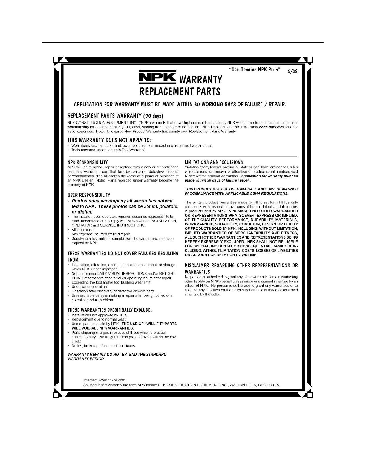
WARRANTY STATEMENTS
50
Page 52
KEYWORDS FOR COMMON DEMO GRAB
BI
MAIN FRAME
BN
ROTARY JOINT ASSEMBLY
BQ4
HYDRAULIC MOTOR
BR
PINION GEAR
BT
SLEWING RING
c11
CYLINDER
c13
PIN LOCK PLATE
c49
PIN (cylinder)
dg1
DRIVE ARM
dg10
LINK BUSHING
dg2
ARM
dg3
CUTTER (sharp)
dg4
CUTTER (blunt)
dg5
SUPPORT BRACKET
dg6
ARM PIN
dg9
FRAME BUSHING
g14
PIN (cylinder rod end)
hm21
MOTOR MOUNTING FLANGE
m2
LINK PIN
m18a
JOINT FITTING (close)
m18b
JOINT FITTING (open)
m27
SWIVEL FLAT TOP
m30
LINK
s9
COVER
COMPONENTS
DG16 SHOWN
51
Page 53
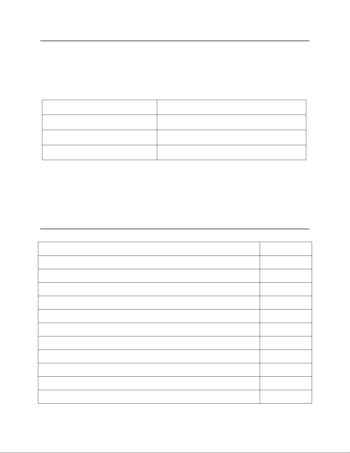
NOTES
EXCAVATOR MANUFACTURER
MODEL NUMBER
SERIES
SERIAL NUMBER
NPK DEMOLITION GRAB MODEL NUMBER ________________
SERIAL NUMBER ______________________________________
NPK INSTALLATION KIT NUMBER ________________________
DATE OF INSTALLATION __________
DATE OF 20 HOUR INSPECTION _________ WARRANTY REGISTRATION SENT
SERVICE RECORD
DATE
52
Page 54
© Copyright 2018 NPK Construction Equipment, Inc. www.npkce.com DG000-9600A
DG16,DG20,DG30,DG40 Demolition Grab Instruction Manual 6-18
 Loading...