

Page 1
ADDENDUM FOR
SEC-05X
SINGLE ELECTRODE AMPLIFIER
SYSTEM
Information on the revised version of the SEC-05X amplifier – to be
used in conjunction with the SEC-05LX user manual
npi 2010
npi electronic GmbH, Hauptstrasse 96, D-71732 Tamm, Germany
Phone +49 (0)7141-9730230; Fax: +49 (0)7141-9730240
[email protected]; http://www.npielectronic.com
Page 2
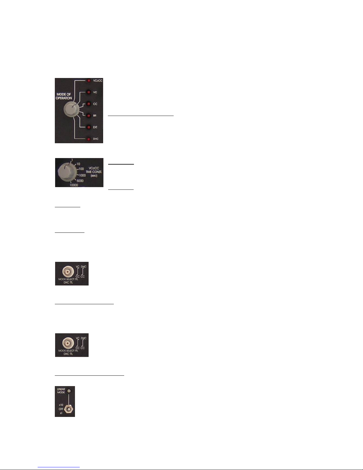
Compared to the SEC-05LX the SEC-05X amplifier is prepared already for additional
operation modes. Therefore, some front panel elements changed slightly compared to the
SEC-05LX.
The MODE OF OPERATION switch has 6 positions. The active mode of
operation is indicated by a red LED beneath the operation mode name.
VCcCC mode (optional)
Voltage Clamp controlled Current Clamp mode (see also additional
sheet). This mode is allows accurate current clamp experiments at
controlled resting potentials. The time constant is set by the VCcCC
TIME CONST. (sec) switch an the left of the front panel.
VC mode
Voltage Clamp mode (see also SEC-05LX manual, page 24)
CC mode
Current Clamp mode (see also SEC-05LX manual, page 24)
BR mode
Bridge mode (see also SEC-05LX manual, page 24)
EXT mode
External mode (see also SEC-05LX manual, page 24). In external mode CC or VC mode can
be selected by a TTL signal applied to the EXTERNAL SELECT BNC / DHC TTL connector
below the MODE OF OPERATION switch; TTL low: CC mode, TTL high: VC mode
DHC mode (optional)
DHC mode (see also additional sheet). In DHC mode CC or VC mode is also selected by a
TTL signal applied to the EXTERNAL SELECT BNC / DHC TTL connector below the
MODE OF OPERATION switch; TTL low: CC mode, TTL high: VC mode
LINEAR mode (optional)
Switch to set the amplifier into the LINEAR mode (see also additional sheet). The
LINEAR mode is indicated by the LINEAR MODE LED above (green: x1, red:
x10).
Page 3

OPERATING INSTRUCTIONS AND
SYSTEM DESCRIPTION OF THE
SEC 05LX SINGLE ELECTRODE
SYSTEMS
WITH APPENDICES:
SEC Cell Model
Tuning Capacity Compensation in SEC Amplifier Systems
SEC-EXT Headstage for Extracellular Recordings with SEC Systems
Calibration of SEC Amplifiers with x10 Headstage
Calibration of SEC Amplifiers with x0.1 Low Voltage Headstage
Synchronization of Two or More SEC Amplifier Systems
SEC Systems with VCcCC Mode
SEC Systems with DHC Mode
SEC Systems with Linear Mode
SEC Systems with Series Resistance Compensation
VERSION 1.9
npi 2011
npi electronic GmbH, Hauptstrasse 96, D-71732 Tamm, Germany
Phone +49 (0)7141-9730230; Fax: +49 (0)7141-9730240
[email protected]; http://www.npielectronic.com
Page 4

1. Safety Regulations
VERY IMPORTANT: Instruments and components supplied by npi electronic are NOT
intended for clinical use or medical purposes (e.g. for diagnosis or treatment of humans)
or for any other life-supporting system. npi electronic disclaims any warranties for such
purpose. Equipment supplied by npi electronic must be operated only by selected,
trained and adequately instructed personnel. For details please consult the GENERAL
TERMS OF DELIVERY AND CONDITIONS OF BUSINESS of npi electronic, D-71732
Tamm, Germany.
1) GENERAL: This system is designed for use in scientific laboratories and must be
operated by trained staff only. General safety regulations for operating electrical devices
should be followed.
2) AC MAINS CONNECTION: While working with the npi systems, always adhere to the
appropriate safety measures for handling electronic devices. Before using any device,
please read manuals and instructions carefully.
The device is to be operated only at 115/230 Volt 60/50 Hz AC. Please check for
appropriate line voltage before connecting any system to mains.
Always use a three-wire line cord and a mains power-plug with a protection contact
connected to ground (protective earth).
Before opening the cabinet, unplug the instrument.
Unplug the instrument when replacing the fuse or changing line voltage. Replace fuse
only with an appropriate specified type.
3) STATIC ELECTRICITY: Electronic equipment is sensitive to static discharges. Some
devices such as sensor inputs are equipped with very sensitive FET amplifiers, which can
be damaged by electrostatic charge and must therefore be handled with care. Electrostatic
discharge can be avoided by touching a grounded metal surface when changing or
adjusting sensors. Always turn power off when adding or removing modules,
connecting or disconnecting sensors, headstages or other components from the
instrument or 19” cabinet.
4) TEMPERATURE DRIFT / WARM-UP TIME: All analog electronic systems are
sensitive to temperature changes. Therefore, all electronic instruments containing analog
circuits should be used only in a warmed-up condition (i.e. after internal temperature has
reached steady-state values). In most cases a warm-up period of 20-30 minutes is
sufficient.
5) HANDLING: Please protect the device from moisture, heat, radiation and corrosive
chemicals.
Page 5
Page 6
Page 7
Page 8
Page 9
Page 10
Page 11
Page 12
Page 13
Page 14

Page 15
Page 16
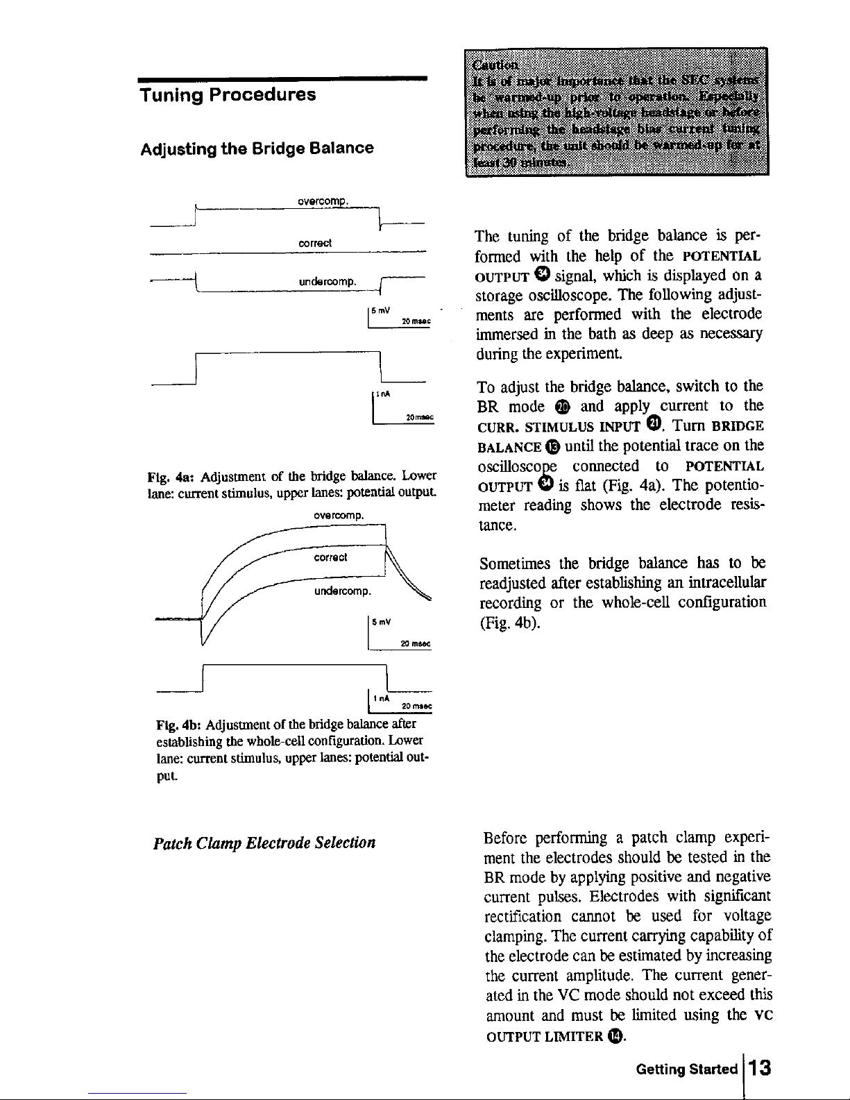
Page 17
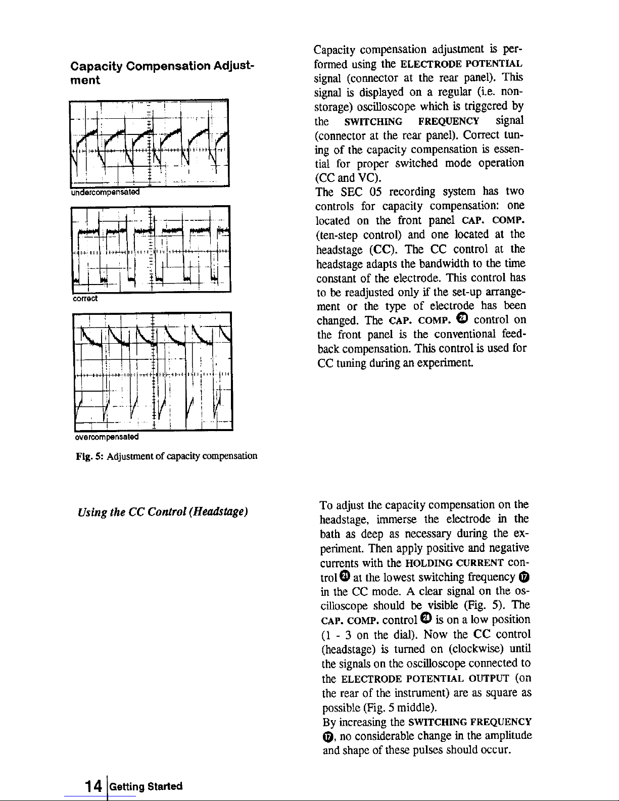
Page 18
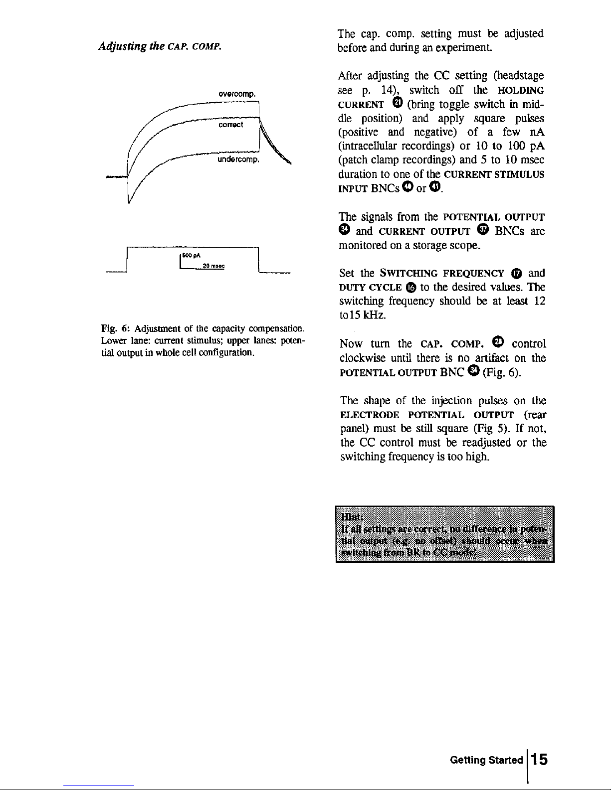
Page 19
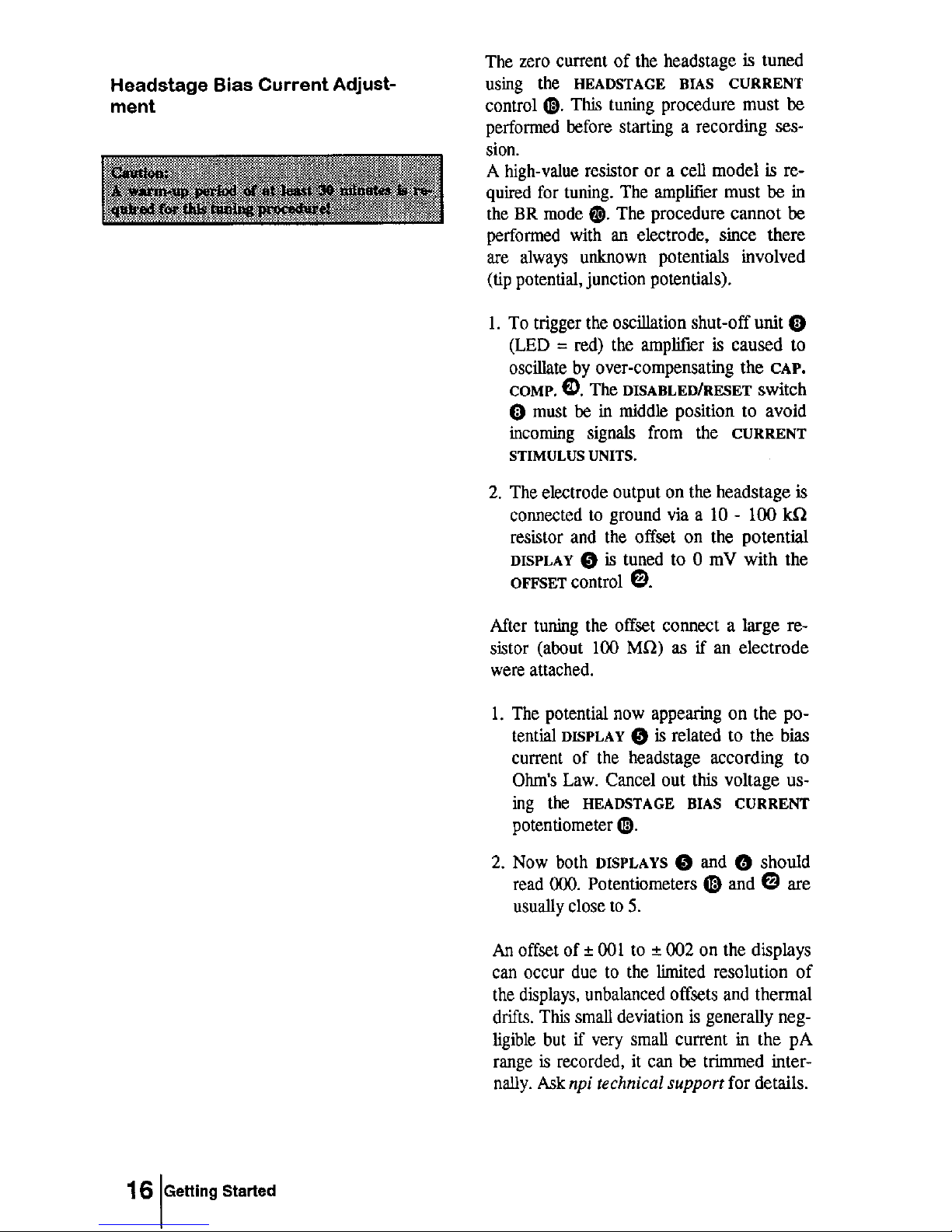
Page 20
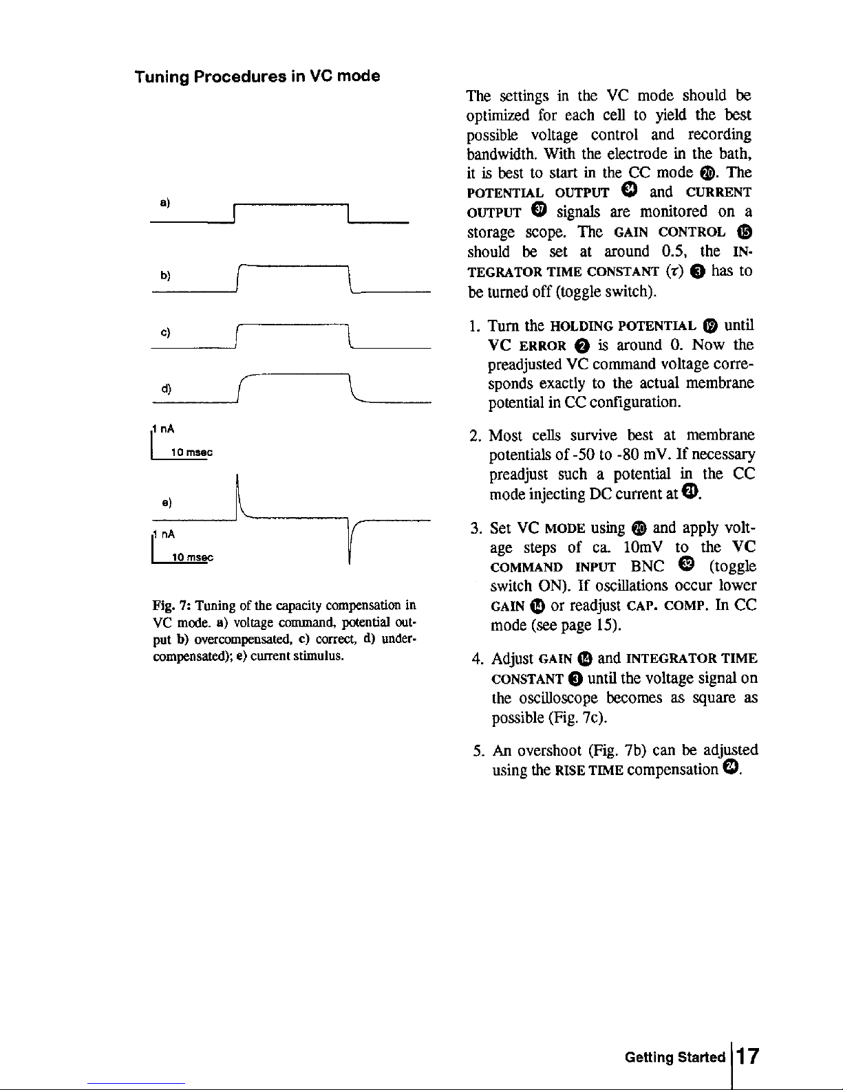
Page 21
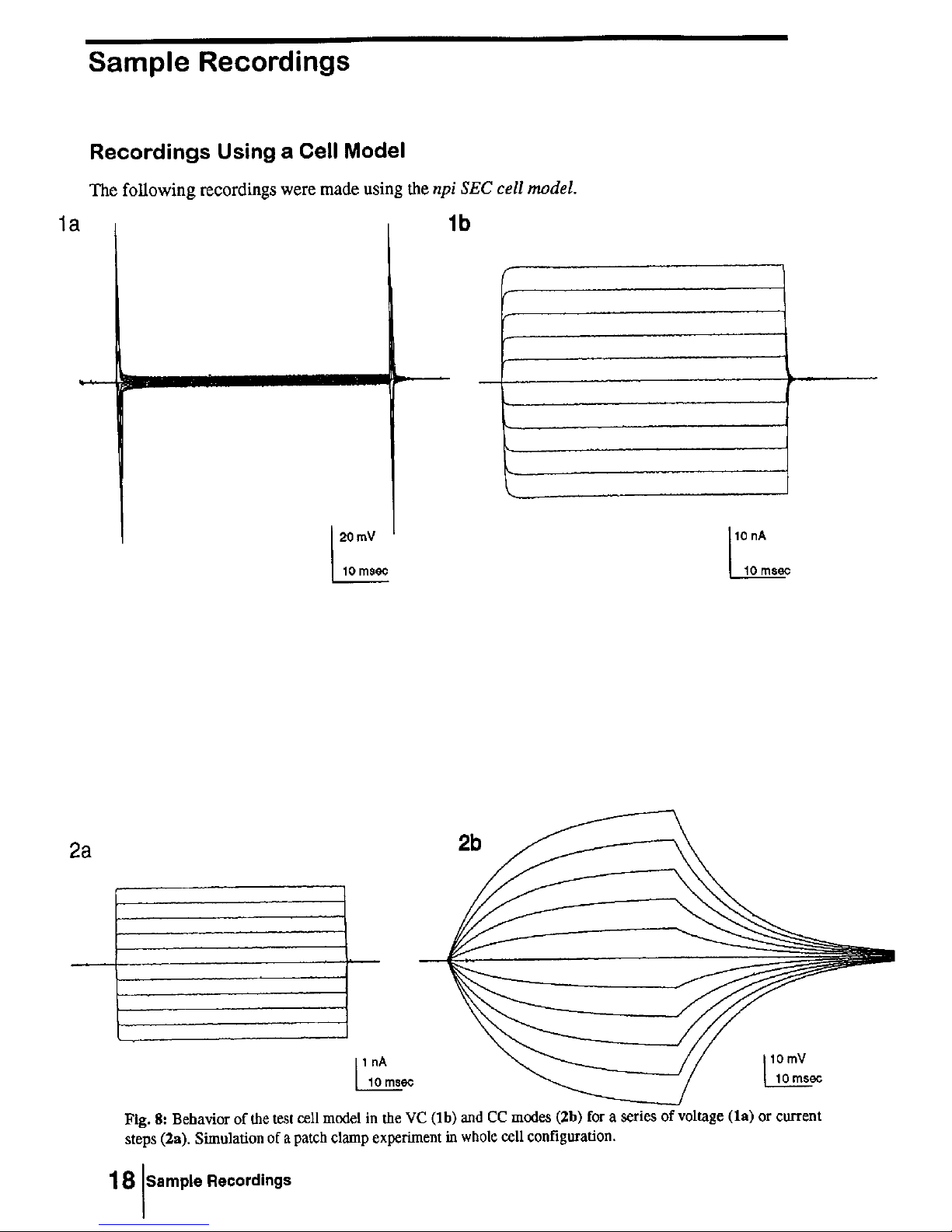
Page 22
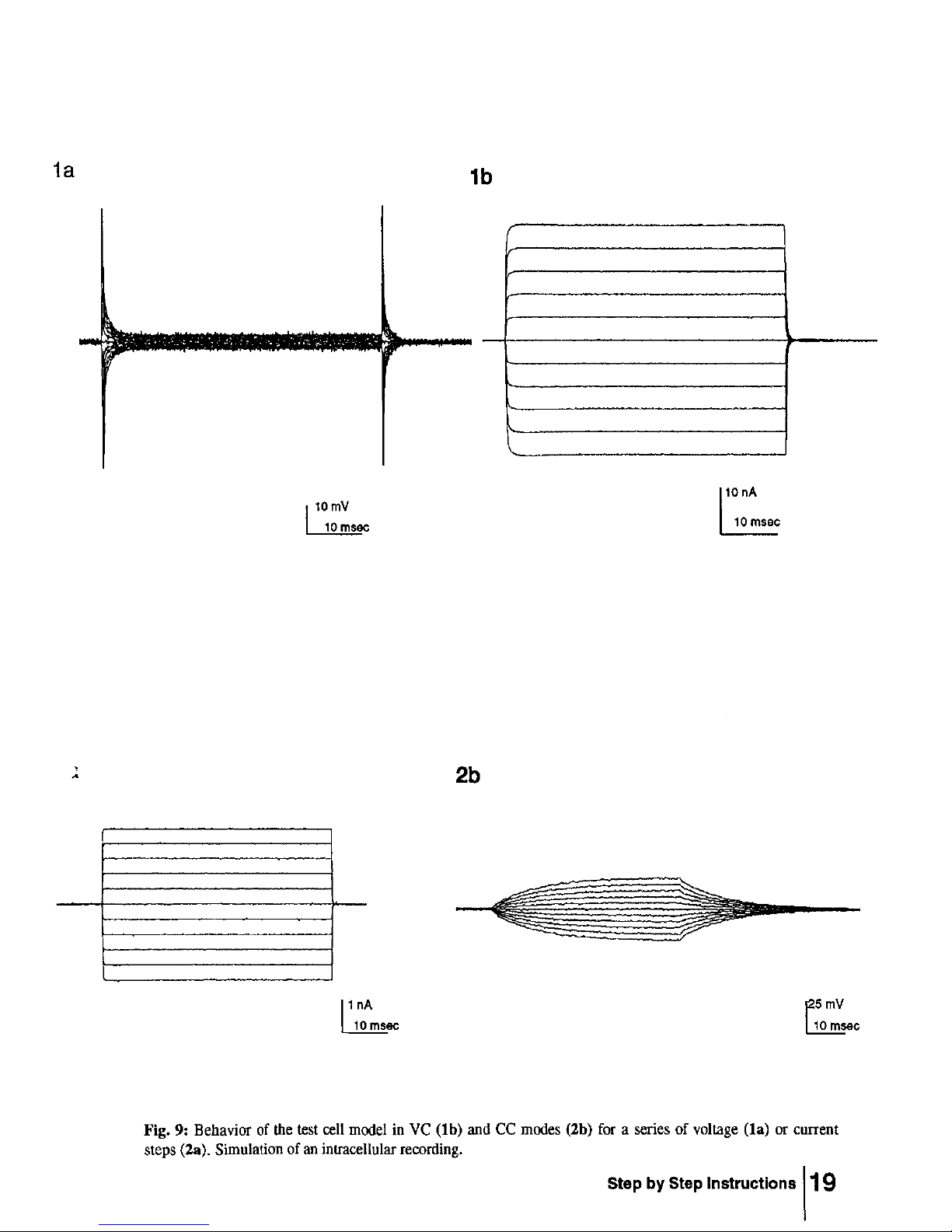
Page 23
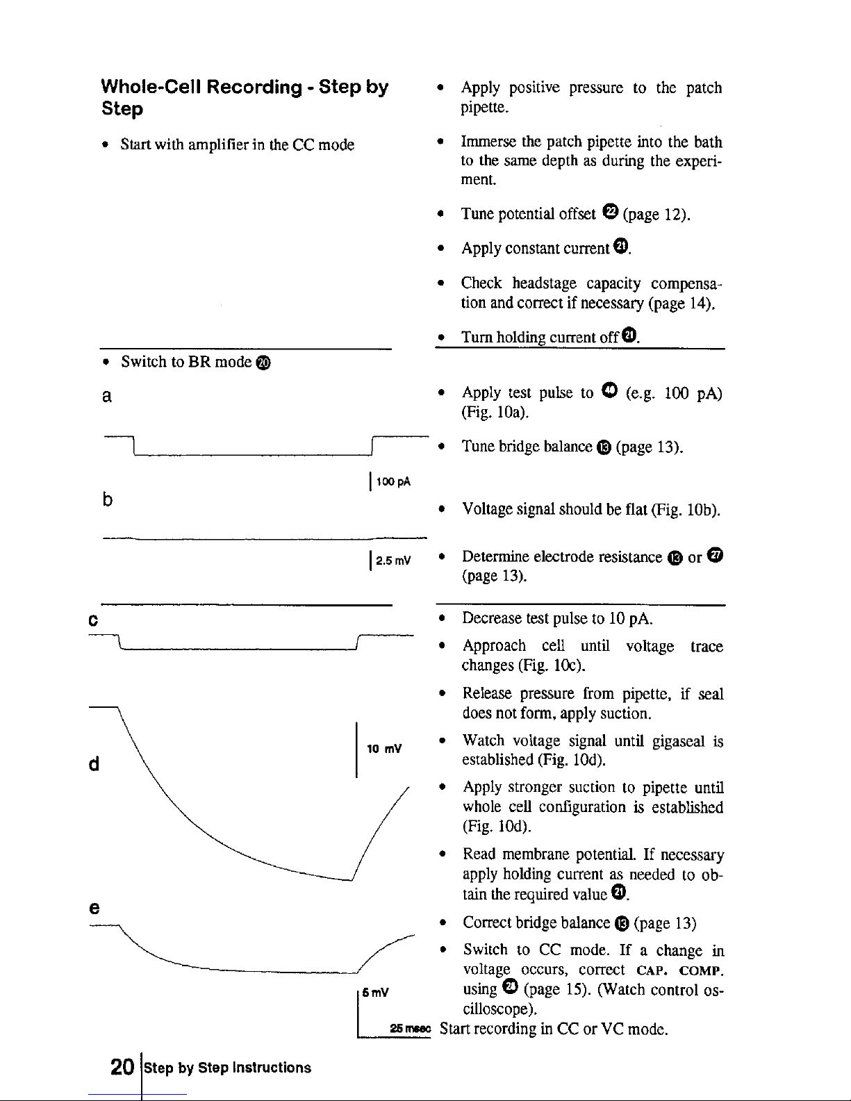
Page 24
Page 25
EXT.EXT.
VCVC
CCCC
BRBR
TTLTTL
0.1nA/V0.1nA/V
1nA/V1nA/V
FREQ.MON.FREQ.MON.
CURR.SENSITIVITY
MONITOR 1...7V
CURRENT STIMULUS INPUTCURRENT STIMULUS INPUT
ONON
OFFOFF
DUTY CYCLEDUTY CYCLE
1/8
1/4
1/2
ONON
OFFOFF
DISABLEDDISABLED
RESETRESET
PENETRATIONPENETRATION
nAnA
R
EL
mVmV
MWMW
+
0
-
HOLDING CURRENT nAHOLDING CURRENT nA
SEC-05LX npiSEC-05LX npi
MODE OF
OPERATION
BRIDGE
BALANCE MW
HEADSTAGE
BIAS CURRENT
CAP.
COMP.
OFFSETOFFSET
HEADSTAGE
INPUT
CURRENT FILTER HzCURRENT FILTER Hz
SWITCHING FREQUENCYSWITCHING FREQUENCY
CURRENT OUTPUT
SENSITIVITY V/nA
0.10.1
0.20.2
0.50.5
11
22
55
1010
POWERPOWER
MODEMODE
x10mVx10mV
FREQ. MON.FREQ. MON.
VC COMMAND INPUTVC COMMAND INPUT
/10mV /10mV/40mV/40mV
GROUNDGROUND
ONON
OFFOFF
ONON
OFFOFF
OFFOFF
+
0
-
HOLDING POTENTIAL mVHOLDING POTENTIAL mV
CURRENT
CLAMP
VOLTAGE
CLAMP
PI-CONTROLLERPI-CONTROLLER
INTEGRATOR TIME CONST. msINTEGRATOR TIME CONST. ms
VC ERRORVC ERROR
GAINGAIN
VC OUTPUT
LIMITER
%%
100100
5050
6060
8080
9090
7070
4040
3030
2020
1010
OFFOFF
RISE TIMERISE TIME
msms
0.40.4
0.20.2
OFFOFF
11
0.80.8
0.60.6
1.21.2
1.41.4
1.61.6
1.81.8
2.02.0
POTENTIAL FILTER HzPOTENTIAL FILTER Hz
AUDIOAUDIO
THRESHOLDTHRESHOLD
DURATIONDURATION
100100
5050
2020
20k20k
1.3k1.3k
700700
1k1k
300300
200200
500500
2k2k
5k5k
3k3k
8k8k
10k10k
13k13k
100100
5050
2020
20k20k
1.3k1.3k
700700
1k1k
300300
200200
500500
2k2k
5k5k
3k3k
8k8k
10k10k
13k13k
CCCC
VCVC
1010
55
0.10.1
POTENTIAL/RESISTANCEPOTENTIAL/RESISTANCE
CURRENTCURRENT
ELECTRODE CLEARELECTRODE CLEAR
100MW100MW
10MW10MW
BUZZBUZZ
-I
max
+I
max
POTENTIAL OUTPUTPOTENTIAL OUTPUT
-8...+7V-8...+7V
SELECT TTLSELECT TTL
-8...+7V-8...+7V
CURRENT OUTPUTCURRENT OUTPUT
REMOTEREMOTE
OSCILLATION
SHUT-OFF
SWITCHING FREQUENCY kHzSWITCHING FREQUENCY kHz
00
0
00
0
00
0
00
0
4 5 64 5 6 4 5 64 5 6
4 5 64 5 6
11
22
33
44
66
55
11
1414
22
1515
2424
33
1919
44
2020
55
66 2727
88
1616
1717
77 99
1010
1111
1212
1313
1818
2222
2828
434342424141
4040
2121
37373838353536362626252534343232303029292323
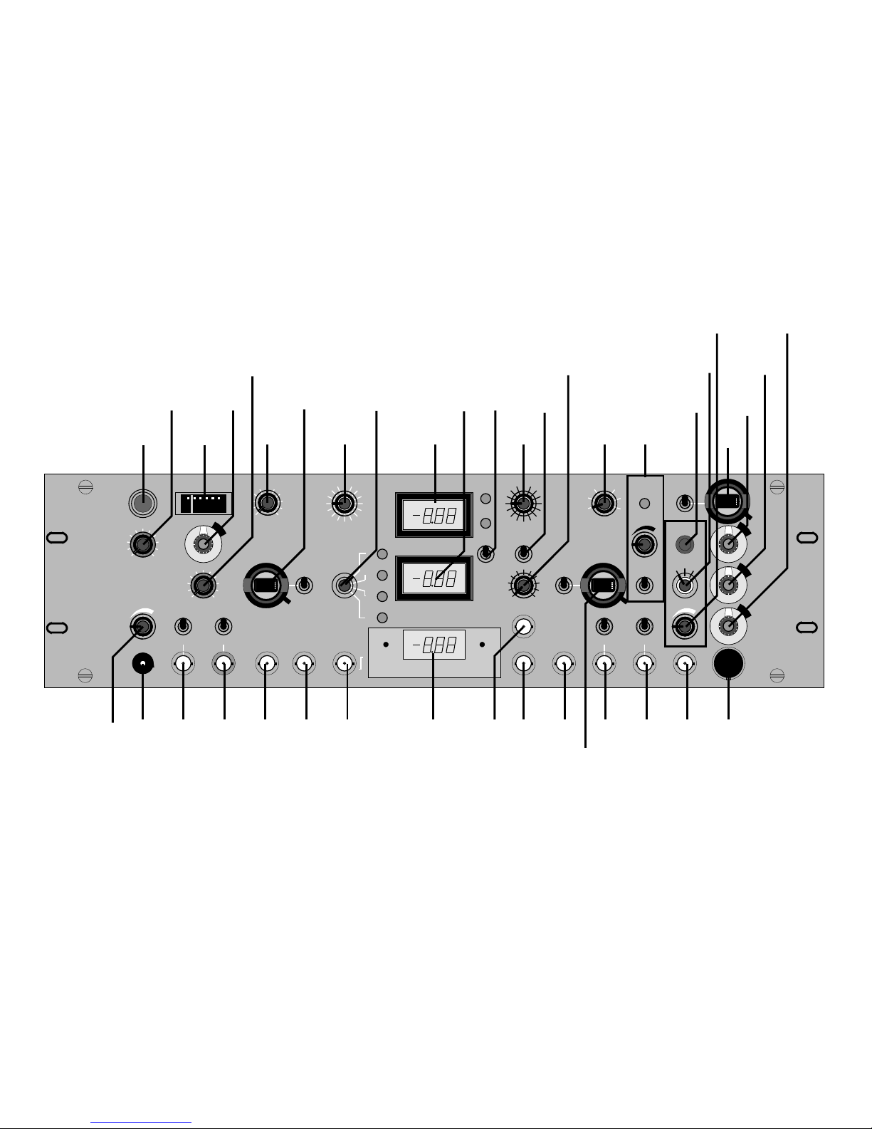
FRONT PANEL VIEW OF THE SEC-05LX AMPLIFIER SYSTEM
Page 26

22
CONTROLS AND
CONNECTORS
FRONT PANEL
ELEMENTS
1 POWER POWER switch
This switch turns on the power supply. The line
fuse, line voltage selector and power cable
connector are located on the rear panel.
2 VC ERROR VC ERROR display
This analog display shows the error in the VC
(voltage clamp) mode (command minus recorded
potential). The desired range of operation is
around zero.
3 INTEGRATOR TIME CONSTANT INTEGRATOR TIME CONSTANT
control and "on/off" switch
· If the control is turned clockwise the
INTEGRATOR part of the PI (proportionalintegral) control is turned on.
· The VC controller then has a PI characteristic
(proportional and integral), which reduces the
error considerably (theoretically to zero).
· The time constant of the integrator is set with
the potentiometer 3.
· Clockwise: time constant is decreased, effect
of integrator is increased.
· When using the integrator, step commands
applied to the VOLTAGE COMMAND
INPUT BNCs (30 / 32)can cause
overshoots, which can be reduced with the
RISE TIME control 24.
4 POTENTIAL FILTER POTENTIAL FILTER switch
(20Hz – 20 kHz, 16 position rotary switch)
· 2 pole or 4-pole tunable Bessel filter (12 or 24
dB/octave) with 16 corner frequencies for the
POTENTIAL OUTPUT (see also CURRENT
FILTER 8.
· The following 16 frequencies can be set:
20, 50, 100, 200, 300, 500, 700, 1k, 1.3k, 2k,
3k, 5k, 8k, 10k, 13k, 20k (Hz)
· The position of this switch is monitored at
the FREQUENCY MONITOR BNC 25
(-8...+7 Volt, 1 Volt / switch position).
Page 27

23
5, 6 DISPLAYS DISPLAYS (3 1/ digits, max. 1999)
· 5 POTENTIAL (mV) / REL (MΩΩ) display:
The upper display shows the recorded
potential in mV (B; C; V modes) or the
electrode resistance in MW (R mode).
· 6 CURRENT (nA) display: The lower
display shows the membrane current in nA
(X.XX nA, 1.00 is 1.00 nA).
7 CURRENT OUTPUT SENSITIVITY CURRENT OUTPUT SENSITIVITY switch
Seven position rotary switch.
· This switch sets the sensitivity of the current
output (0.1, 0.2, 0.5, 1, 2, 5, 10 V/nA),
· The position of this switch is monitored at
the CURRENT SENSITIVITY MONITOR
BNC 35 (1...+7 Volt, 1 Volt / switch
position).
8 CURRENT FILTER CURRENT FILTER switch
(20Hz – 20 kHz, 16 position rotary switch)
· 2 pole or 4-pole tunable Bessel filter (12 or 24
dB/octave) with 16 corner frequencies.
· The following 16 frequencies can be set:
20, 50, 100, 200, 300, 500, 700, 1k, 1.3k, 2k,
3k, 5k, 8k, 10k, 13k, 20k (Hz)
· The position of this switch is monitored at
the FREQUENCY MONITOR BNC 38
(-8...+7 Volt, 1 Volt / switch position).
9 OSCILLATION SHUTOFF OSCILLATION SHUTOFF unit
Disconnects current injection and capacity
compensation if parasitic oscillations occur.
· A red/green LED shows the state of the
system (red = shut-off triggered).
· THRESHOLD: Sets the threshold for
shutoff activation.
· DISABLE/RESET switch: resets or disables
oscillation shut-off unit.
10 – 12 PENETRATION CELL PENETRATION unit
This unit is used to clean the tip of the electrode
and to facilitate the puncture of the cell
membrane.
· The unit can be operated by a remote switch
connected to the REMOTE BNC 42
(active LOW).
· The duration can be set by the DURATION
control 10.
Page 28

24
· Mode select switch 12 can preset 3 modes:
· BUZZ mode: overcompensation of the
capacity compensation effective in all
four modes of operation (R, B, C, V
modes).
· +Imax / -Imax modes: Application of
maximum positive or negative current to
the microelectrode (+/- 100 nA, standard
headstage).
13 BRIDGE BALANCE and BRIDGE BALANCE (MW)
10MΩΩ/100MΩΩ range switch In the B (=bridge) mode the electrode resistance
is compensated with this control (ten turn
potentiometer, clockwise); calibrated in MW.
· The range can be set to 10 MW (100 = 10
MW, max resistance 100 MW) for low
resistance patch microelectrodes or to the
· range 100 MW (100 = 100 MW, maximum
resistance is 1000 MW for sharp
microelectrodes using a toggle switch.
14 VC OUTPUT LIMITER VC OUTPUT LIMITER (Current Limit)
Under certain experimental conditions, it is
necessary to limit the current in the voltage
clamp mode (e.g. in order to prevent the blocking
of the electrode or to protect the preparation).
This is possible with an electronic limiter, which
sets the current range between 0-100%.
15 VC GAIN VC GAIN
This control sets the gain of the VC controller (5-
5000). The gain must be as high as possible.
16 DUTY CYCLE DUTY CYCLE (1/8; 1/4; 1/2)
In the discontinuous modes (V and C modes)
this switch sets the ratio between current
injection and potential recording mode (12.5%;
25% or 50% of each switching period).
17 SWITCHING FREQUENCY SWITCHING FREQUENCY
In the switched modes (V and C modes) the
switching frequency for the discontinuous
current injection is set with this control (ca. 1kHz
- 50kHz). The selected frequency is indicated
with the display 36.
18 HEADSTAGE BIAS CURRENT HEADSTAGE BIAS CURRENT control
With this 10 turn control the output current of
the headstage can be tuned to zero (see following
chapters).
Page 29

25
19 HOLDING POTENTIAL (mV) HOLDING POTENTIAL control
and +/0/- POLARITY SWITCH (see also HOLDING CURRENT 21).
The command signal for the voltage clamp mode
(V mode) is a sum of following input signals:
· 19 HOLDING POTENTIAL (mV), with a
+/0/- switch for selecting the polarity
· 30/ 32 analog input BNCs (/10mV; /40mV),
· Calibration: XXX mV, 100 is 100 mV
20 MODE OF OPERATION MODE OF OPERATION
Rotary switch for selection of the three recording
modes of operation, the selected mode of
operation is indicated by a red LED near the
rotary switch.
· EXT: EXTERNAL CONTROL MODE.
In this position the mode of operation can be
preset by a TTL pulse applied to the MODE
SELECT BNC connector 26.
· B: BRIDGE MODE (see BRIDGE
BALANCE control 13)
· C: CURRENT CLAMP MODE using a
discontinuous current injection.
· V: VOLTAGE CLAMP MODE using a
discontinuous feedback.
21 HOLDING CURRENT (nA) HOLDING CURRENT control
and +/0/- POLARITY SWITCH The current injected through the electrode in the
current clamp modes (B and C modes) is the
sum of the following input signals:
· 21 HOLDING CURRENT (nA): With this
control a constant current can be generated,
(ten turn potentiometer, clockwise),
calibrated in nA. The polarity is selected with
a +/0- toggle switch near the control.
· 40 / 41 Analog input BNCs, 1nA/V; 0.1nA/V
· Calibration is X.XX nA (100 is 1.00 nA)
corresponding to the calibration of the
CURRENT DISPLAY 6.
22 OFFSET OFFSET control
Control to zero the output of the electrode
preamplifier (ten turn potentiometer, 0mV = 5);
up to +/-400mV offset can be compensated.
23 AUDIO AUDIO MONITOR loudness control
Output volume of audio monitor (voltage to
frequency conversion of recorded potential.)
Page 30

26
24 RISE TIME RISE TIME control
Sometimes it is necessary to limit the rise time of
a voltage clamp pulse especially in connection
with PI-controllers to avoid overshooting of the
potential. See also 3.
25 FREQUENCY MONITOR FREQUENCY MONITOR BNC connector
The position of the POTENTIAL FILTER
switch 4 is monitored at the FREQUENCY
MONITOR BNC (-8...+7 Volt, 1 Volt / switch
position).
26 MODE SELEC (TTL) MODE SELECT BNC connector
If the EXTERNAL CONTROL MODE. is set
with the MODE of OPERATION switch 20 the
mode of operation can be preset by a TTL pulse
applied to the MODE SELECT BNC connector
26. A LOW signal presets C mode (switched
current clamp mode), a HIGH signal presets V
mode (switched voltage clamp mode).
See also MODE OF OPERATION 20.
27 REL-Mode Switch and REL mode switch
MΩΩ LED (light emitting diode) This switch activates the automatic electrode
resistance measurement mode.
· In this mode brief current pulses are applied
to the microelectrode and the resistance is
displayed on the upper display in MW.
· The activation of this mode is indicated by
the MΩΩ LED above the switch. The
electrode resistance is measured correctly
regardless of DC offsets.
· Important: The displayed resistance may be
dependent on the correct setting of the
capacity compensation (see 28)
28 CAPACITY COMPENSATION CAPACITY COMPENSATION
Fine adjustment for the compensation of input
capacitance (ten turn potentiometer, clockwise),
up to 20 pF can be compensated. (Coarse
compensation control on headstage (CC) and
tuning procedure see CAPACITY
COMPENSATION chapter).
Page 31

27
29 GROUND GROUND plug
This connector is linked to the internal system
ground, which has no connection to the 19"
cabinet and the mains ground to avoid ground
loops. Ground connectors are also on the rear
panel (see REAR PANEL ELEMENTS,
GND/EARTH connectors).
30-32 VC COMMAND INPUT VC COMMAND INPUT BNC connectors
(see also CUR.STIMULUS INPUT 40/41)
The command signal for the voltage clamp mode
(V mode) is a sum of following input signals:
· 19 HOLDING POTENTIAL (mV), with a
+/0/- switch for selecting the polarity
· 32 analog input BNC (/10mV = 10 mV/mV),
· 30 analog input BNC (/40mV = 40 mV/mV).
· Each input BNC is equipped with an on/off
toggle switch that can be used to ground
unused inputs to avoid noise pickup.
34 POTENTIAL OUTPUT (x10mV) POTENTIAL OUTPUT BNC connector
BNC connector monitoring the recorded
potential with a gain of ten.
35 CURR.SENSITIVITY MONITOR CURRENT SENSITIVITY MONITOR
This BNC connector provides eight output
voltages (0-7V, 1 Volt per switch position)
corresponding to the eight positions of the
CURRENT OUTPUT SENSITIVITY switch.
See also 7.
36 SWITCHING FREQUENCY SWITCHING FREQUENCY (kHz) display
The selected switching frequency (see 17) is
displayed with a 3 digit display. In the linear
modes (B and R modes) it must show zero.
37 CURRENT OUTPUT CURRENT OUTPUT BNC connector
BNC connector on the front panel, monitoring
the effective (average) current passed through the
electrode.
38 FREQUENCY MONITOR FREQUENCY MONITOR BNC connector
The position of the CURR. FILTER switch 8 is
monitored at the FREQUENCY MONITOR
BNC (-8...+7 Volt, 1 Volt / switch position).
40 / 41 CURRENT STIMULUS INPUT CURRENT STIMULUS INPUT
The current injected through the electrode in the
current clamp modes (B and C modes) is the
sum of the following input signals:
Page 32

28
· 21 HOLDING CURRENT (nA): With this
control a constant current can be generated,.
The polarity is selected with a +/0- toggle
switch near the control
· 40 1 nA/Volt Analog input (BNC connector).
Calibration: 1 Volt = 1 nA
· 41 0.1 nA/V Analog input (BNC connector).
Calibration: 1 volt = 100 pA
· Each input BNC is equipped with an on/off
toggle switch that can be used to ground
unused inputs to avoid noise pickup.
42 REMOTE REMOTE
BNC connector for activating the
PENETRATION UNIT. See also 10.
43 HEADSTAGE INPUT HEADSTAGE INPUT connector
The headstages are connected via a flexible cable
and a 12-pole connector to the mainframe.
Caution: Please always adhere the appropriate
safety regulations (see SAFETY REGULATION
chapter). When connecting or disconnecting the
headstages from the 19" cabinet connector please
turn power off!
Page 33

29
REAR PANEL
ELEMENTS
SWITCHING OUTPUTS SWITCHING OUTPUTS (see Fig. 3)
These outputs provide signals for tuning
of the switched operation modes (V and
C modes). In the V and C modes these
signals are necessary for tuning the
capacity compensation (see following
chapter).
· SW FREQUENCY MONITOR:
BNC-connector monitoring the
selected switching frequency (+5V
pulses), used to trigger the
oscilloscope which displays the
switching pulses.
· ELECTRODE POTENTIAL
(VEL): BNC connector monitoring
the electrode potential, i.e. the
response of the electrode to the
discontinuous current injection
GROUND / PROTECTIVE EARTH GROUND / PROTECTIVE EARTH
Connectors; see also 29.
In order to avoid ground loops, the
internal zero (ground) signal of the
instrument is not connected to the mains
ground and the cabinet. The cabinet and
mains ground are connected to the
green/yellow connector, the internal
ground is connected to the yellow
connector.
CAUTION: (see also page 2)
· Always use a three-wire line cord and
a mains power-plug with a protection
contact connected to ground.
· Before opening or closing the
connection between the GROUND /
EARTH plugs disconnect mains
power-plug.
SERIAL NUMBER SERIAL NUMBER / TYPE / DATE
In this field the serial number, type and
date of production of the instrument are
indicated.
Page 34

30
POWER POWER / FUSE / LINE VOLTAGE
SELECTOR / FUSE /
LINE VOLTAGE SELECTOR
The power chord is connected by a
standardized coupling which comprises
also the fuse, voltage selector and a line
filter. With 230V AC the fuse must be
0.63A (slow), with 115V AC it must be
1.25A (slow).
CAUTION: (see also page 2)
• Always use a three-wire line cord and
a mains power-plug with a protection
contact connected to ground.
• Before opening the cabinet
disconnect mains power-plug.
• Disconnect mains power-plug when
replacing the fuse or changing line
voltage.
•
Replace fuse only by appropriate
specified type.
SYNC. MODE CONNECTORS / SWITCH see Appendix “Synchronization of Two
or More SEC Amplifier Systems”
Page 35

31
REFERENCES
General
Brennecke, R. and Lindemann, B. (1971): A Chopped-Current Clamp for Current Injection
and Recording of Membrane Polarization with Single Electrodes of Changing Resistance,
T.I.T. Journal of Life Sciences, 1:53-58
Brennecke R, Lindemann B (1974) Theory of a membrane-voltage clamp with discontinuous
feedback through a pulsed current clamp. Rev. Sci. Instrum. 45:184-188
Brennecke, R. and Lindemann, B. (1974): Design of a fast voltage clamp for biological
membranes, using discontinuous feed-back, Rev. Sci. Instrum., 45:656-661
Brown, T.H. and Johnston, D. (1983): Voltage-Clamp Analysis of Mossy Fiber Synaptic Input
to Hippocampal Neurons, J. Neurophysiol., 50:487-507
Dhein, St. (1998) Cardiac Gap Junction Channels, Physiology, Regulation, Patophysiology
and Pharmacology, Karger, Basel
Dietzel, I. D., D. Bruns, H. R. Polder and H. D. Lux (1992) Voltage Clamp Recording,
in Kettenmann, H. and R. Grantyn (eds.) Practical Electrophysiological Methods, Wiley-Liss,
New York
Draguhn, A., Pfeiffer, M., Heinemann, U. and Polder, H.R. (1997) A simple hardware model
for the direct observation of voltage-clamp performance under realistic conditions.
J.Neurosci.Methods 78: 105-113.
Finkel AS, Gage PW (1985) Conventional Voltage Clamping With Two Intracellular
Microelectrodes. In: Smith TG, Lecar H, Redman SJ, Gage PW (eds) Voltage and Patch
Clamping With Microelectrodes. Chapter 4. The William and Wilkins Company, Baltimore,
pp 47-94.
Finkel AS, Redman SJ (1985) Optimal Voltage Clamping With Single Microelectrode. In:
Smith TG, Lecar H, Redman SJ, Gage PW (eds) Voltage and Patch Clamping With
Microelectrodes. Chapter 5. The William and Wilkins Company, Baltimore, pp 95-120
Ferreira, H.H., and Marshall, M.W. (1985) The biophysical basis of excitability, Cambridge
University Press, Cambridge
Fröhr F, Orttenburger F (1981) Introduction to Electronic Control Engineering. Siemens
Aktiengesellschaft Berlin, Munich
Johnston, D. & Brown, T.H. (1983): Interpretation of Voltage-Clamp Measurements in
Hippocampal Neurons, J. Neurophysiol., 50:464-486
Juusola, M (1994) Measuring complex admittance and receptor current by single electrode
voltage-clamp. J. Neurosci. Meth. 53:1-6
Page 36

32
Kettenmann H, and R Grantyn (eds).Practical Electrophysiological Methods Willey-Liss,
New York (1992).
Misgeld U, Müller W, Polder HR (1989) Potentiation and suppression by eserine of muscarinic
synaptic transmission in the guinea-pig hippocampal slice. J. Physiol. 409: 191-206
Müller, A., M. Bachmann, R. Berkels, S. Dhein, H.R. Polder and W. Klaus (1998) Switched
single electrode amplifiers allow precise measurement of gap junction conductance, American
Journal of Physiology, in press
Ogden DC (1994) Microelectrode electronics. In Ogden, D.C. (ed.) (1994) Microelectrode
techniques. The Plymouth Workshop Handbook. 2nd edition, The Company of Biologists
Limited, Cambridge.
Polder HR (1984) Entwurf und Aufbau eines Gerätes zur Untersuchung der
Membranleitfähigkeit von Nervenzellen und deren Nichtlinearität nach der potentiostatischen
Methode (Voltage-Clamp-Methode) mittels einer Mikroelektrode, Diplomarbeit (M.Sc.EE
thesis), Technische Universität München
Polder HR, Swandulla D, Konnerth A, and Lux HD (1984) An Improved, High Current Single
Electrode Current/Voltage Clamp System, Pflügers Archiv, 402:R35
Polder HR, Swandulla D (1990) Design and optimal tuning of single and double electrode
voltage clamp systems using methods of modulus hugging. Pflügers Archiv 415:S77
Polder, H.R., R. Schliephacke, W. Stühmer and H. Terlau (1997) A new, switched mode
double electrode clamp amplifier avoiding series resistance errors, in Elsner, N. and H. Wässle
(eds.) Göttingen Neurobiology Report 1997, Thieme Verlag Stuttgart
Richter, D.W., Pierrefiche, O., Lalley, P.M. and Polder, H.R. (1996) Voltage-clamp analysis of
neurons within deep layers of the brain. J.Neurosci.Methods 67: 121-131.
Smith TG, Lecar H, Redman SJ, Gage PW (ed) Voltage and Patch Clamping With
Microelectrodes. The William and Wilkins Company, Baltimore 1985
Weckström M, Kouvaleinen E., Juusola M (1992): Measurement of cell impedance in
frequency domain using discontinuous current clamp and white-noise modulated current
injection. Pflügers Arch. 421:469-472
Wilson, W.A. and Goldener, M.M. (1975): Voltage Clamping with a Single Microelectrode, J.
Neurobiol., 6:411-422
Page 37

33
Selected Literature About the
npi SEC 05/10 Single Electrode Clamp Systems
Recording Methods and Voltage Clamp Technique
Dietzel, I. D., D. Bruns, H. R. Polder and H. D. Lux (1992) Voltage Clamp Recording, in
Kettenmann, H. and R. Grantyn (eds.) Practical Electrophysiological Methods, Wiley-Liss, NY.
Misgeld, U., W. Müller and H. R. Polder (1989) Potentiation and Supression by Eserine of
Muscarinic Synaptic Transmission in the Guinea-Pig Hipocampal Slice, J.Physiol., 409: 191-206
Polder, H.R. and Swandulla, D. (2001) The use of control theory for the design of voltage
clamp systems: a simple and standardized procedure for evaluating system parameters. J.
Neuroscience Methods, 109: 97-109
Richter, D.W., Pierrefiche, O., Lalley, P.M. and Polder, H.R. (1996) Voltage-clamp analysis of
neurons within deep layers of the brain. J.Neurosci.Methods 67: 121-131
Windhorst, U. and H. Johansson (eds.) Modern Techniques in Neuroscience Research,
Springer, Berlin, Heidelberg, New York, 1999
Selection of switching frequency, electrode time constant, capacity compensation
Juusola, M (1994) Measuring complex admittance and receptor current by single electrode voltage clamp. J. Neurosci. Meth. 53:1-6
Weckström M, Kouvaleinen E., Juusola M (1992): Measurement of cell impedance in frequency
domain using discontinuous current clamp and white-noise modulated current injection. Pflügers
Arch. 421:469-472
Comparison of recording methods (sharp electrode, whole cell, perforated patch)
Jarolimek, W. and U. Miseld (1993) 4-Aminopyridine-induced synaptic GABA-B currents in
granule cells of the guinea-pig hippocampus, Pflügers Arch 425:491-498.
Kapur, M.F.Yeckel. R.Gray, and D. Johnston (1998) L-Type Calcium Channels Are Required for
One Form of Hippocampal Mossy Fiber LTP, J. Neurophysiol. 77:2181-2190
Coating of sharp microelectrodes for VC recordings
Juusola, M., Seyfarth E.A. and French, A.S., (1997): Fast coating of glass-capillary microelectrodes
for single-electrode voltage clamp, J. Neurosci. Meth. 71:199-204
Capacitive transients in VC recordings
Sutor, B., Hablitz, J.J. (1989): Excitatory postsynaptic potentials in rat neocortical neurons in vitro. I.
Electrophysiological evidence for two distinct EPSPs. Journal of Neurophysiology 61, 607-620
Page 38

34
Leak subtraction
Sutor, B., Zieglgänsberger, W. (1987): A low-voltage activated, transient calcium current is
responsible for the time-dependent depolarizing inward rectification of rat neocortical neurons in
vitro. Pflügers Archiv 410: 102-111
Cardiac cells / double cell voltage clamp method
Dhein, St. (1998) Cardiac Gap Junction Channels, Physiology, Regulation, Patophysiology and
Pharmacology, Karger, Basel
Lu, J., J. F. Dalton, IV, D. R. Stokes, and R. L. Calabrese (1997) Functional role of Ca2+ currents
in graded and spike- synaptic transmission between leech heart interneurons. J. Neurophysiol.
77:1779–1794
Double Cell Recordings / Gap Junctions
Dhein, S., Wenig, S., Grover, R., Tudyka, T., Gottwald, M., Schaefer, T. & Polontchouk, L.
(2002) Protein kinase Calpha mediates the effect of antiarrhythmic peptide on gap junction
conductance. Cell Adhes Commun, 8, 257-264.
Müller, A., M. Lauven, R. Berkels, S. Dhein, H.R. Polder and W. Klaus (1999) Switched single
electrode amplifiers allow precise measurement of gap junction conductance, American Journal of
Physiology (Cell) Vol. 276, No.4 C980-C988, April 1999
Weng, S., Lauven, M., Schaefer, T., Polontchouk, L., Grover, R. & Dhein, S. (2002)
Pharmacological modification of gap junction coupling by an antiarrhythmic peptide via protein
kinase C activation. FASEB J., 16, 1114-1116.
Simultaneous recordings with two SEC amplifiers
Haag, J, and A. Borst (1996) Amplification of high-frequency synaptic inputs by active
dendritic membrane processes, Nature Vol 379, 639-641
Haag, J. and Borst, A. (2001). Recurrent Network Interactions Underlying Flow-Field Selectivity of
Visual Interneurons. J.Neurosci 21 (15), 5685–5692.
Haag, J. and Borst, A. (2002). Dendro-Dendritic Interactions between Motion-Sensitive
Large-Field Neurons in the Fly. J.Neurosci 22 (8), 3227–3233.
Simultaneous intracellular recordings during voltammetric measurements
Kudernatsch, M., Sutor, B.: Cholinergic modulation of dopamine overflow in the rat neostriatum: a
fast cyclic voltammetric study in vitro. Neuroscience Letters 181, 107-112, 1994.
Schlösser, B., Kudernatsch, M.B., Sutor, B., ten Bruggencate, G. (1995): d -, m - and k -opioid
receptor agonists inhibit dopamine overflow in rat neostriatal slices. Neuroscience Letters 191, 126130,
Staining, visualization, imaging and infrared video microscopy
Dodt, H.U and W. Zieglgänsberger (1994) Infrared videomicroscopy: a new look at neuronal
structure and functure, Trends in Neurosciences, Vol. 19 No. 11 453-458
Kapur A., M. Yeckel and D. Johnston (2001) Hippocampal mossy fiber activity evokes Ca2+
release in CA3 pyramidal neurons via a metabotropic glutamate receptor pathway, Neuroscience
107 (1):59-69
Page 39

35
Röhrig, G., Klausa, G., and Sutor, B. (1996) Intracellular acidification reduced gap junction coupling
between immature rat neocortical pyramidal neurons, Journal of Physiology
490.1 pp. 31-49
Single, S. and A. Borst (1998) Dendritic Integration and Its Role in Computing Image Velocity,
Science. Vol. 281:1848-50
Single, S. and Borst, A. (2002) Different Mechanisms of Calcium Entry Within Different Dendritic
Compartments. J.Neurophysiol. 87, 1616–1624.
Performance test with active cell model
Draguhn, A., Pfeiffer, M., Heine mann, U. and Polder, H.R. (1997) A simple hardware model for the
direct observation of voltage-clamp performance under realistic conditions. J. Neurosci. Methods
78: 105-113.
Hybrid Clamp
Dietrich, D., Clusmann, H. and T. Kral (2002). Improved hybrid clamp : resolution of tail currents
following single action potentials. J.Neurosci.Meth. 116, 55-63.
LTP / LDP Investigations
Blank, T., Nijholt, I., Eckart, K., and Spiess, J. (2002). Priming of long-term potentiation in mouse
hippocampus by corticotropin-releasing factor and acute stress: implications for hippocampusdependent learning. J.Neurosci 22:3788-94.
Dodt, H., Eder, M., Frick, A., and Zieglgansberger, W. (1999). Precisely localized LTD in the
neocortex revealed by infrared-guided laser stimulation. Science 286, 110-113.
Eder, M., Zieglgansberger, W., & Dodt, H. U. (2002). Neocortical long-term potentiation and longterm depression: site of expression investigated by infrared-guided laser stimulation. J.Neurosci. 22,
7558-7568.
Marsicano, G., Wotjak, C. T., Azad, S. C., Bisognok, T., Rammes, G., Casciok, M. C., Hermann,
H., Tang, J., Hofmann, C., Zieglgänsberger, W., Di Marzok, V. & Lutz, B. (2002). The endogenous
cannabinoid system controls extinction of aversive memories. Nature 418, 530-533.
Nakazawa K., Quirk, M. C., Chitwood, R. A., Watanabe, M., Yeckel, M. F., Sun, L. D., Kato,
A., Carr, C. A., Johnston, D., Wilson, M. A. & Tonegawa, M. A. (2002). Requirement for
Hippocampal CA3 NMDA Receptors in Associative Memory Recall. Science 297, 211-218.
Rammes, G., Steckler, T., Kresse, A., Schutz, G., Zieglgansberger, W., and Lutz, B. (2000).
Synaptic plasticity in the basolateral amygdala in transgenic mice expressing dominant-negative
cAMP response element-binding protein (CREB) in forebrain. Eur.J.Neurosci. 12, 2534-2546.
Intra- and extracellular recording
Sillaber, I., Rammes, G., Zimmermann, S., Mahal, B., Zieglgänsberger, W., Wurst, W., Holsboer,
F. & Spanagel, R. (2002). Enhanced and Delayed Stress-Induced Alcohol Drinking in Mice
Lacking Functional CRH1 Receptors. Science 296, 931-933.
Perforated Patch
Hanganu, I. L., Kilb, W., & Luhmann, H. J. (2002). Functional synaptic projections onto subplate
neurons in neonatal rat somatosensory cortex. J.Neurosci. 22, 7165-7176.
Page 40

36
Selected Literature Voltage & Patch Clamp Techniques
Publications in scientific journals:
Armstrong, C.M. and Chow, R.H. (1987) Supercharging: A method for improving patch-clamp
performance. Biophys.J. 52: 133-136.
Bekkers, J.M. and Stevens, C.F. (1996) Cable properties of cultured hippocampal neurons
determined from sucrose-evoked miniature EPSCs. J.Neurophysiol. 75: 1250-1255.
Blanton, M.G., Lo Turco, J.J. and Kriegstein, A.R. (1989) Whole cell recording from neurons in
slices of reptilian and mammalian cerebral cortex. J.Neurosci.Meth.30:203-10.
Brennecke, R. and Lindemann, B. (1974) Theory of a membrane -voltage clamp with discontinuous
feedback through a pulsed current clamp. Rev.Sci.Instrum. 45: 184-188.
Bush, P.C. and Sejnowsky, T.J. (1993) Reduced compartmental models of neocortical pyramidal
cells. J.Neurosci.Methods 46: 159-166.
De Schutter, E. and Bower, J.M. (1994) An active membrane model of the cerebellar purkinje cell:
II. Simulation of synaptic responses. J.Neurophysiol. 71: 401-419.
Dietrich, D., Clusmann, H. and T. Kral (2002). Improved hybrid clamp: resolution of tail currents
following single action potentials. J.Neurosci.Meth. in press.
Draguhn, A., Pfeiffer, M., Heinemann, U. and Polder, H.R. (1997) A simple hardware model for the
direct observation of voltage -clamp performance under realistic conditions. J.Neurosci.Methods 78:
105-113.
Edwards, F.A., Konnerth, A., Sakmann, B. and Takahashi, T. (1989) A thin slice preparation for
patch clamp recordings from neurons of the mammalian nervous system. Pflügers Arch. 414: 600-
612.
Eisenberg, R.S. and Engel, E. (1970) The spatial variation of membrane potential near a small source
of current in a sperical cell. J. Gen. Physiol. 55:736-757.
Engel, E., Barcilon, V. and Eisenberg, R.S. (1972) The interpretation of current-voltage relations
recorded from a spherical cell with a single microelectrode.
Biophys. J. 12:384-403.
Gorman, A.L.F. and Mirolli, M. (1972) The pasive electrical properties of the membrane of a
molluscan neurone. J. Physiol. 227:35-49.
Hamill, O.P., Marty, A., Neher, E., Sakmann, B. and Sigworth, F.J. (1981) Improved patch-clamp
techniques for high-resolution current recording from cells and cell-free membrane patches. Pflügers
Arch. 391: 85-100.
Page 41

37
Henze, D.A., Cameron, W.E. and Barrionuevo, G.N. (1996) Dendritic morphology and its effects
on the amplitude and rise-time of synaptic signals in hippocampal CA3 pyramidal cells.
J.Comp.Neurol. 369: 331-344.
Jackson, M.B. (1992) Cable analysis with the whole-cell patch clamp. Theory and experiment.
Biophys.J. 61: 756-766.
Johnston, D. (1981) Passive cable properties of hippocampal CA3 pyramidal neurons. Cell. Mol.
Neurobiol. 1: 41-55.
Johnston, D. and Brown, T.H. (1983) Interpretation of voltage -clamp measurements in hippocampal
neurons. J.Neurophysiol. 50: 464-486.
Kawato, M. (1984) Cable properties of a neuron model with non-uniform membrane resistivity. J.
Theor. Biol. 111: 149-169.
Mainen, Z.F. and Sejnowski, T.J. (1996) Influence of dendritic structure on firing pattern in model
neocortical neurons. Nature 382: 363-366.
Magistretti, J., Mantegazza, M., Guatteo, E. and E. Wanke (1996). Action potentials recorded with
patch -clamp amplifiers: are they genuine? Trends Neurosci. 19, 530-534
Major, G. (1993) Solutions for transients in arbitrarily branching cables: III. Voltage clamp
problems. Biophys.J. 65: 469-491.
Müller, W. and Lux, H.D. (1993) Analysis of voltage-dependent membrane currents in spatially
extended neurons from point-clamp data. J.Neurophysiol. 69: 241-247.
Polder, H.R. and Swandulla, D. (1990) Design and optimal tuning of single and double electrode
voltage clamp systems using methods of modulus hugging. Pflügers Arch. 415: S77.
Polder, H.R., Swandulla, D., Konnerth, A. and Lux, H.D. (1984) An improved high current single
electrode current/voltage clamp system. Pflügers Arch. 406: R43.
Polder, H.R. and Swandulla, D (2001) The use of control theory for the design of voltage clamp
systems: a simple and standardized procedure for evaluating system parameters. J. Neuroscience
Methods, 109: 97-109
Rall, W. (1959) Branching dendritic trees and motoneuron resistivity. Exp. Neurol. 1: 491-527.
Rall, W (1969) Time constants and electrotonic length of membrane cylinders and neurons. Biophys.
J. 9: 1483-1508.
Richter, D.W., Pierrefiche, O., Lalley, P.M. and Polder, H.R. (1996) Voltage-clamp analysis of
neurons within deep layers of the brain. J.Neurosci.Methods 67: 121-131.
Sala, F. and Sala, S. (1994) Sources of error in single-electrode voltage-clamp techniques: a
computer simulation study. J.Neurosci.Methods 53: 189-197.
Page 42

38
Spruston, N., Jaffe, D.B., Williams, S.H. and Johnston, D. (1993) Voltage - and space-clamp errors
associated with the measurement of electrotonically remote synaptic events. J.Neurophysiol. 70:
781-802.
Spruston, N. and Johnston, D. (1992) Perforated patch-clamp analysis of the passive membrane
properties of three classes of hippocampal neurons.
J. Neurophysiol. 67: 508-529.
Staley, K.J., Otis, T.S. and Mody, I. (1992) Membrane properties of dentate gyrus granule cells:
Comparison of sharp microelectrode and whole-cell recordings. J.Neurophysiol. 67: 1346-1358.
Silver, R.A., Traynella, S.F. and Cull-Candy, S.G. (1992) Rapid time-course miniature and evoked
excitatory currents at cerebellar synapses in situ. Nature 355: 163-166.
Williams, S.H. and Johnston, D. (1991) Kinetic properties of two anatomically distinct excitatory
synapses in hippocampal CA3 pyramidal neurons. J.Neurophysiol. 66: 1010-1020.
Wilson, W.A. and Goldner, M.M. (1975) Voltage clamping with a single microelectrode.
J.Neurobiol. 6: 411-422.
Page 43

39
Book chapters:
Armstrong, C. M. and Gilly, W.F. (1992) Access resistance and space clamp problems associated
with whole -cell patch clamping. In: Methods in enzymology. Vol. 207, Academic Press, San Diego,
CA, USA.
Dietzel, I. D., Bruns, D., Polder, H. R. and Lux, H. D. (1992) Voltage clamp recording. In:
Kettenmann, H. and Grantyn, R. (eds.) Practical electrophysiological methods. Wiley-Liss, NY.
Eisenberg, R.S. and Johnson, E.A. (1970) Three-dimensional electrical field problems in physiology.
In: Butler; J.V.A. and Noble, D. (eds.) Progress in Biophysics and Molecular Biology, Vol. 20,
Pergamon Press, Oxford, p 1.
Finkel, A.S. and Gage, P.W. (1985) Conventional voltage clamping with two intracellular
microelectrodes. In: Smith, T.G., Lecar, H., Redman, S.J. and Gage, P.W. (eds.) Voltage and patch
clamping with microelectrodes. Chapter 4. The William and Wilkins Company, Baltimore, p 47.
Finkel, A.S. and Redman, S.J. (1985) Optimal voltage clamping with single microelectrode. In:
Smith, T.G., Lecar, H., Redman, S.J. and Gage, P.W. (eds.) Voltage and patch clamping with
microelectrodes. Chapter 5. The William and Wilkins Company, Baltimore, p 95.
Jack, J. (1979) An introduction to linear cable theory. In: Scmitt, F.O. and Worden, F.G. (eds.) The
Neurosciences, Fourth Study Program. MIT Press, Cambridge, p 423.
Marty, A. and Neher, E. (1995) Tight-seal whole -cell recording. In: Sakmann, B. and Neher, E.
(eds.) Single channel recording. 2nd edition, Plenum Press, New York.
Ogden, D. and Stanfield, P. (1994) Patch clamp techniques for single channel and whole-cell
recording. In: Ogden, D. (ed.) Microelectrode techniques. 2nd edition, The Company of Biologists
Ltd., Cambridge.
Rall, W. (1977) Core conductor theory and cable properties of neurons. In: Kandel, E.R. (ed.)
Handbook of Physiology, Section I, The Nervous System, Volume I, Part I, American Physiological
Society, Bethesda, p. 39
Sigworth, F.J. (1995) Electronic design of the patch-clamp. In: Sakmann, B. and Neher, E. (eds.)
Single channel recording. 2nd edition, Plenum Press, New York.
Page 44

40
Whole books:
Boulton, A.A., Baker, G.B. and Vanderwolf, C.H. (eds.) (1990) Neurophysiological techniques.
Basic methods and concepts. Humana Press, Clifton, New Jersey.
Cole, K.S. (1968) Membranes ions and impulses. University of California Press, Berkely, CA.
Ferreira, H.G. and Marshall, M.W. (1985) The biophysical basis of excitability. Cambridge
University Press, Cambridge.
Fröhr, F. (1985) Electronic control engine ering made easy. An introduction for beginners. Siemens
AG, Berlin and Munich.
Horowitz, P. and Hill, W. (1989) The art of electronics. Cambridge University Press, NY
Jack, J.J.B., Noble, D. and Tsien, R.W. (1975) Electric current flow in excitable cells. Claredon
Press, Oxford.
Kettenmann, H. and Grantyn, R. (eds.) (1992) Practical electrophysiological methods.
Wiley-Liss, New York.
Neher, E. (1974) Elektrische Meßtechnik in der Physiologie. Springer-Verlag, Berlin.
Numberger, M. and Draguhn, A. (eds.) (1996) Patch-Clamp-Technik. Spektrum Akad. Verl.,
Heidelberg, Berlin, Oxford.
Ogden, D.C. (ed.) (1994) Microelectrode techniques. The Plymouth Workshop Handbook.
2nd edition, The Company of Biologists Limited, Cambridge.
Polder, H.R. (1984) Entwurf und Aufbau eines Gerätes zur Untersuchung der Membranleitfähigkeit
von Nervenzellen und deren Nichtlinearität nach der potentiostatischen Methode (Voltage -ClampMethode) mittels einer Mikroelektrode. Diplomarbeit, Technische Universität München.
Rudy, B. and Iverson, L.E. (eds.) (1992) Ion channels. In: Methods in enzymology. Vol.
207, Academic Press, San Diego, CA, USA.
Sahm III, W.H. and Smith, M.W. (eds.) (1984) Optoelectronics manual. 3rd edition, General
Electric Company, Auburn, NY, USA.
Sakmann, B. and Neher, E. (eds.) (1995) Single channel recording. 2nd Edition, Plenum.NY,.
Smith, T.G., Jr., Lecar, H., Redmann, S.J. and Gage, P.W. (eds.) (1985) Voltage and patch
clamping with microelectrodes. American Physiological Society, Bethesda; The Williams & Wilkins
Company, Baltimore.
Windhorst, U. and H. Johansson (eds.) Modern Techniques in Neuroscience Research,
Springer, Berlin, Heidelberg, New York, 1999
Page 45
OPERATING INSTRUCTIONS AND
SYSTEM DESCRIPTION FOR THE
PASSIVE CELL MODEL
FOR SINGLE ELECTRODE
SWITCHED AMPLIFIERS
VERSION 4.0
npi 2010
npi electronic GmbH, Hauptstrasse 96, D-71732 Tamm, Germany
Tel. +49-(0)7141-9730230, Fax: +49-(0)7141-9730240
[email protected]; http://www.npielectronic.com
Page 46
Passive Cell Model User Manual
_________________________________________________________________________________________________________________
___________________________________________________________________________
version 4.0 page 2
1. Introduction
The cell model is designed to be used to check the function of the SEC amplifier either
1. just after unpacking to see whether the instrument has been damaged during transport or
2. to train personnel in using the instrument or
3. in case of trouble to check which part of the setup does not work correctly e.g. to find out
whether the amplifier is broken or if something is wrong with the electrodes or holders
etc.
The passive cell model consists only of passive elements, i.e. resistors that simulate the
resistance of the cell membrane and the electrodes, and capacitances that simulate the
capacitance of the cell membrane. A switch allows simulation of two different cell types: a
“medium sized” cell with 100 M membrane resistance and 100 pF membrane capacitance,
or a “small” cell with 500 M and 22 pF. Electrode immersed into the bath or SEAL
formation can be mimicked as well. The headstage of the amplifier can be connected to one of
two different types of electrodes (see below).
1.1. Cell Model Description
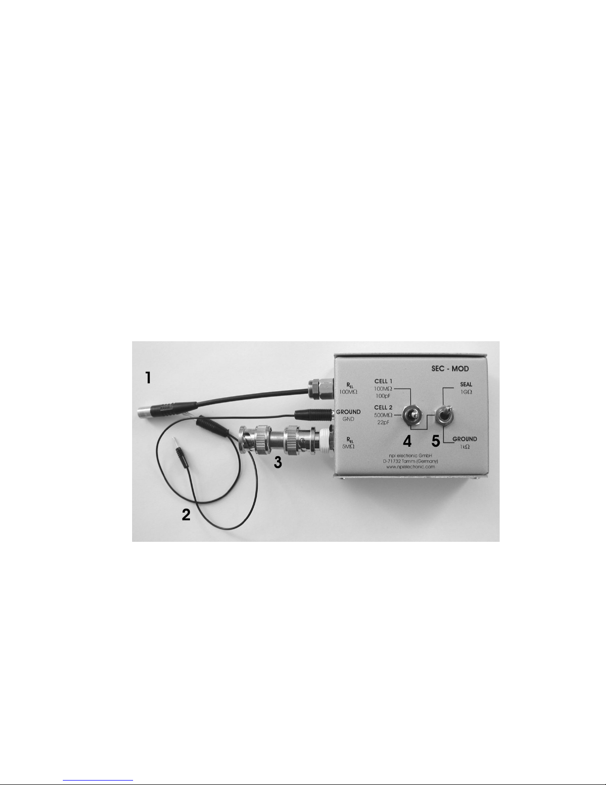
Figure 1: SEC-MOD passive cell model
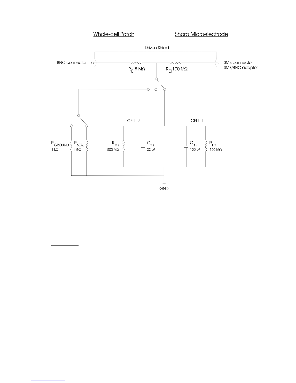
1, 3: connectors for the headstage, 1: electrode resistance: 100 M, 3: electrode resistance:
5 M
2: GND ground connector, to be connected to GND jack of the headstage
4: CELL: switch for cell membrane representing a membrane of either 100 M and
100 pF (CELL 1) or 500 M and 22 pF (CELL 2).
5: In GROUND (lower) position the electrodes are connected to ground via a 1 k
resistor. In SEAL (upper) position are connected to a 1 G resistor simulating the
formation of a GIGASEAL with a patch electrode.
Page 47
Passive Cell Model User Manual
_________________________________________________________________________________________________________________
___________________________________________________________________________
version 4.0 page 3
Figure 2: Schematic diagram of the passive cell model
1.2. Connections and Operation
Connections
Turn POWER switch of the amplifier off.
a) For simulation of an experiment using a suction electrode
Connect the BNC jack of the cell model to the BNC connector P
EL
of the headstage.
b) For simulation of an experiment using a sharp electrode
Connect the SMB connector of the cell model to the BNC connector PEL at the headstage.
For headstages with BNC connector use the supplied SMB to BNC adapter.
For a) and b)
Connect GND of the cell model to GND of the headstage.
Do not connect DRIVEN SHIELD
Page 48

Passive Cell Model User Manual
_________________________________________________________________________________________________________________
___________________________________________________________________________
version 4.0 page 4
Simulation of electrode in the bath
Set switch #4, Figure 1 to the lower position.
Set switch #5, Figure 1 to GROUND position. The 1 k resistor simulates the resistance
of the bath solution. This can be used to train cancellation of offsets, using the bridge
balance and using the capacity compensation.
Simulation of SEAL formation
Set switch #4, Figure 1 to the lower position.
Set switch #5, Figure 1 to SEAL position. The 1 G resistor simulates the SEAL
resistance when forming a GIGASEAL in patch clamp experiments.
Simulation of intracellular recording
Intracellular recordings can be mimicked with one of two cells with different properties. Use
the 100 M electrode connector (#1, Figure 1) for an experiment with sharp electrodes or the
5 M electrode connector (#3, Figure 1) for simulating an experiment with patch electrodes.
Switch the CELL membrane switch (see #4, Figure 1) to the desired position (CELL 1 or
CELL 2).
Turn all controls at the amplifier to low values (less than 1) and the OFFSET in the range
of 5 (zero position) and the OSCILLATION SHUTOFF in the DISABLED position.
Turn POWER switch of the amplifier on.
Now you can adjust the amplifier (see below) and apply test pulses to the cell model. The
upper position the CELL membrane switch (CELL 1) simulates a cell with a resistance of
100 M and a capacitance of 100 pF. In the lower position (CELL 2) a cell membrane with
500 M and 22 pF is simulated.
Page 49

Version 1.11 page 1
APPENDIX
TUNING CAPACITY COMPENSATION IN
SEC AMPLIFIER SYSTEMS
VERSION 1.11
For accurate measurements in switched mode, it is essential that the capacity of the electrode
is fully compensated.
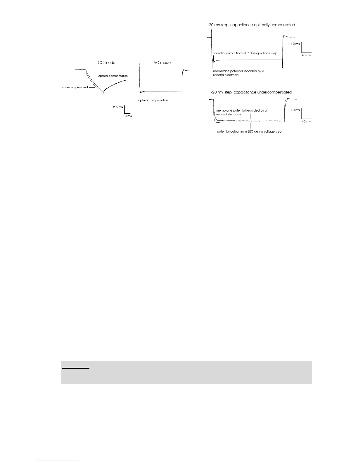
Important: Wrong compensation of electrode capacity leads to errors in measurements done
in switched mode of the amplifier (see Figure 2).
Microelectrode selection: Electrodes must be tested before use. This is done by applying
positive and negative current pulses. Electrodes that show significant changes in resistance
(rectification) cannot be used for intracellular recordings. By increasing the current amplitude
the capability of the electrode to carry current can be estimated. The test current must cover
the full range of currents used in the experiment. For details see (3).
Switching frequency is a key parameter of discontinuous single electrode clamp (dSEVC)
systems. The switching frequency determines the accuracy, speed of response, and signal-to
noise ratio of the dSEVC system (3)(6). Since its launch in 1984, one of the outstanding
features of the SEC series of single electrode voltage / current clamp systems has been the
ability to record routinely with high switching frequencies in the range of tens of kilohertz,
regardless of the microelectrode resistance (1). Principles of the dSEVC technique are found
in (1)(2).
Looking back: In the early eighties, when the design of the SEC 1L system was started, single
electrode clamping began to gain importance beside the two classical intracellular methods:
bridge recording or whole cell patch clamp recording. The great advantage compared to the
whole cell recording method using a patch amplifier was the elimination of series resistance
due to the time sharing protocol. No current flow during voltage recording means no
interference from the series resistance regardless of its value. Voltage clamp recordings
became possible with sharp microelectrodes in deep cell layers. The historical weak point of
this method was the low switching frequency due to the fact that stray capacities around the
microelectrode could not be compensated sufficiently.
The SEC systems provided a solution for this problem. With their improvements on capacity
compensation electronics, they could be used with switching frequencies of tens of kHz even
with high resistance microelectrodes. What are the technical principles that make possible
such high switching frequencies?
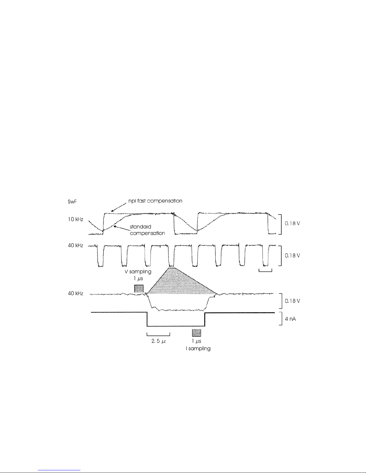
In SEC systems a special protocol is used to rapidly compensate the microelectrode. Figure 1
shows the compensation scheme of a sharp microelectrode immersed 3 mm in cerebrospinal
fluid. Here the increase in speed can be seen clearly. Recordings under such conditions and
possible applications have been presented in several papers (e.g. (3)).
Page 50
Tuning Capacity Compensation
Version 1.11 page 2
Criteria for the selection of the switching frequency
Which are the most important criteria for the selection of the switching frequency? This
question was analyzed in detail by M. Weckstrom and colleagues (4)(5). They presented a
formula that describes the conditions for obtaining reliable results during a switching single
electrode clamp:
f
e
> 3fsw, fsw > 2fs, fs > 2ff >fm
fe: upper cutoff frequency of the microelectrode
fsw: switching frequency of the dSEVC
fs: sampling frequency of the data acquisition system
f
f
: upper cutoff frequency of the lowpass filter for current recording,
f
m
: upper cutoff frequency of the membrane.
Example (6): With the time constant of 1-3 µs recorded for the electrodes used in this study,
fe is 80-160 kHz, the selected switching frequency of the dSEVC was 30 - 50kHz (calculated
range is 25-53 kHz), data were sampled at 10 kHz and the current signals have been filtered at
5 kHz. These settings are currently used for recordings in many labs.
The principle of operation in switched mode is shown below.
Figure 1: Microelectrode artifact settling.
Compensation of stray capacities with a SEC 05 amplifier. The upper trace shows the
comparison between the standard capacity compensation and the fast compensation of the
SEC systems. After full compensation the settling time of the microelectrode is reduced to a
few microseconds allowing very high switching frequencies (here: 40 kHz, middle and lower
trace). The microelectrode was immersed 3 mm deep in cerebrospinal fluid. Microelectrode
resistance: 45 M, current: 1 nA, duty cycle 25%. SwF: switching frequency.
Original data kindly provided by Prof. Diethelm W. Richter, Goettingen. For details see (3).
Page 51
Tuning Capacity Compensation
Version 1.11 page 3
Figure 2: Errors resulting from wrong compensation of the electrode capacity.
Original data kindly provided by Ajay Kapur. For details see (7).
Tuning Procedure (see also chapter “Getting Started”, pages 14, 15):
First part: basic setting
In SEC systems the capacity compensation of the electrode is split into two controls, the
coarse control in the headstage and a the fine control at the front panel of the amplifier. The
aim of the first part of the tuning procedure is to set the coarse capacity compensation at the
headstage, so that an optimal, wide range of CAP.COMP. at the amplifier is achieved.
Insert the electrode into the electrode holder and connect it to the amplifier.
Immerse the electrode, as deep as it will be during the experiment, into the bath solution.
Set the CAP.COMP. control at the amplifier (potentiometer #24 at the front panel) to a
value around 2 and turn COARSE CAPACITY COMPENSATION at the headstage to the
leftmost position. Select a DUTY CYCLE as desired (#24 at the front panel).
Connect the BNC connector ELECTRODE POTENTIAL OUTPUT at the rear panel to an
oscilloscope and trigger with the signal at BNC connector SWITCHING FREQUENCY
(also at the rear panel). The oscilloscope should be in external trigger mode. The time
base of the oscilloscope should be in the range of 250 µs.
Set the amplifier in CC mode and select the lowest switching frequency (1 to 2 kHz)
Apply positive or negative current to the electrode using the HOLDING CURRENT
control (potentiometer #21 at the front panel).
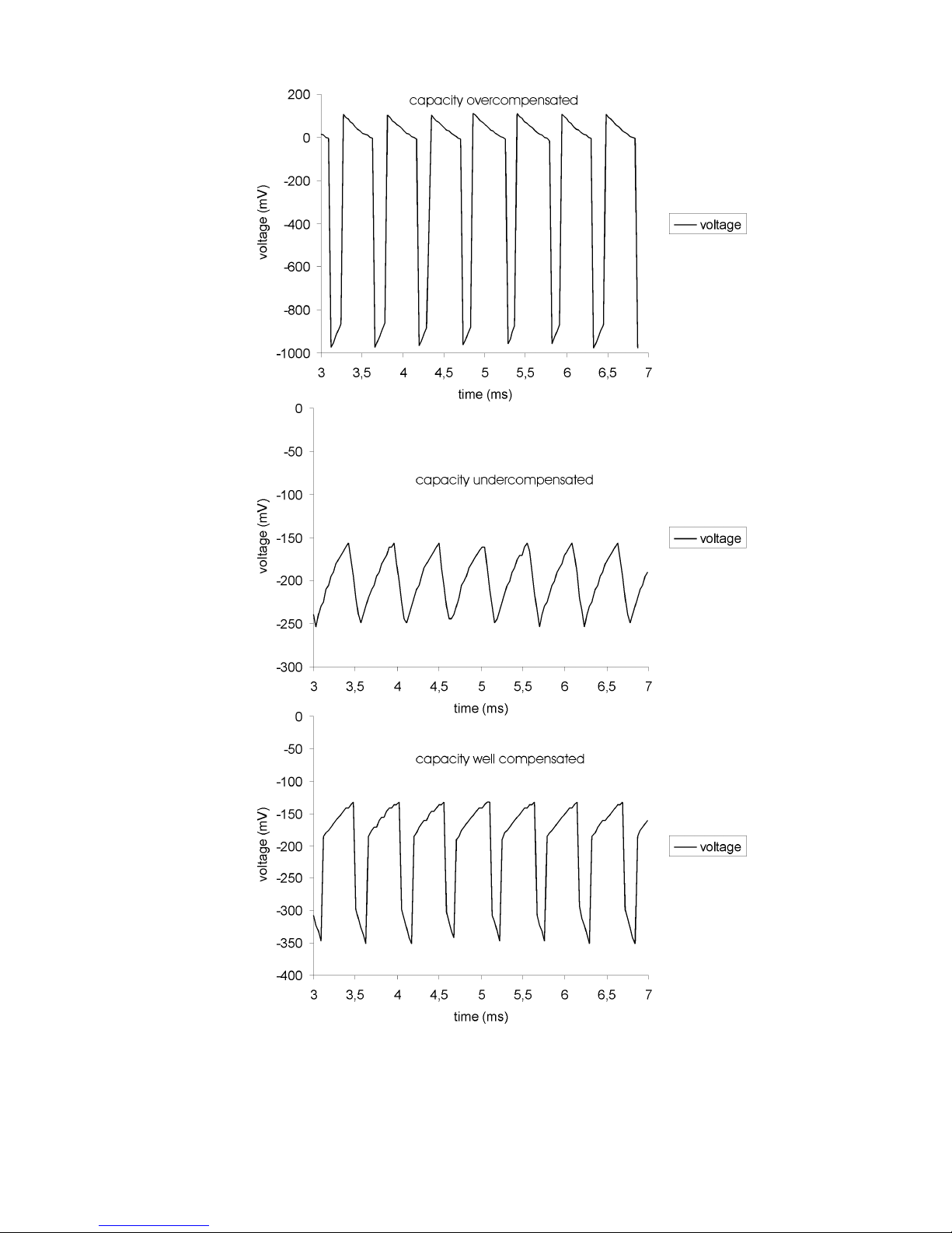
You should see a signal at the oscilloscope similar to those in Figure 3. Turn the
COARSE CAPACITY COMPENSATION carefully clockwise until the signal becomes
as square as possible (lower diagram in Figure 3).
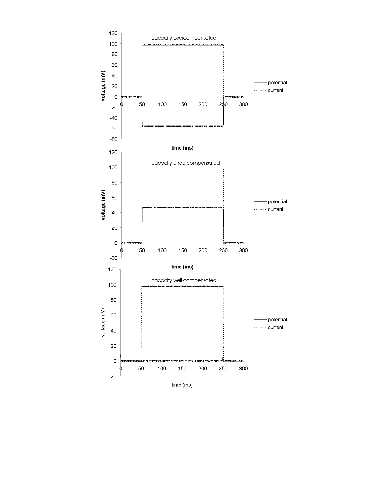
Important: If you use a model cell (e.g. to train yourself in adjusting the capacity
compensation) the capacity of the model cell is always present. Thus, you will get an
approximately square shaped signal with a slight slope as shown in Figure 4 (lower panel).
Increase the switching frequency to at least 15 kHz. The amplitude and shape of the signal
should not change considerably.
Page 52
Tuning Capacity Compensation
Version 1.11 page 4
Figure 3: Tuning of the coarse capacity compensation with an electrode (resistance100 M)
in the bath. Time course of the signal at ELECTRODE POTENTIAL OUTPUT is shown
(holding current: -1 nA, duty cycle: ¼, switching frequency: 2 kHz).
Page 53
Tuning Capacity Compensation
Version 1.11 page 5
Figure 4: Tuning of the coarse capacity compensation. Time course of the signal at
ELECTRODE POTENTIAL OUTPUT is shown (holding current: -1 nA, duty cycle: ¼,
switching frequency: 2 kHz). A model cell was connected (electrode resistance 100 M).
Page 54
Tuning Capacity Compensation
Version 1.11 page 6
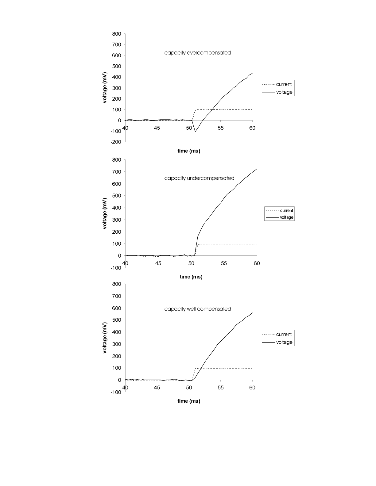
Figure 5: Capacity compensation of the electrode in the bath (electrode resistance: 100 M,
Current stimulus: 1 nA, duty cycle: ¼, switching frequency: 2 kHz). Current stimulus and
electrode potential are shown.
Page 55
Tuning Capacity Compensation
Version 1.11 page 7
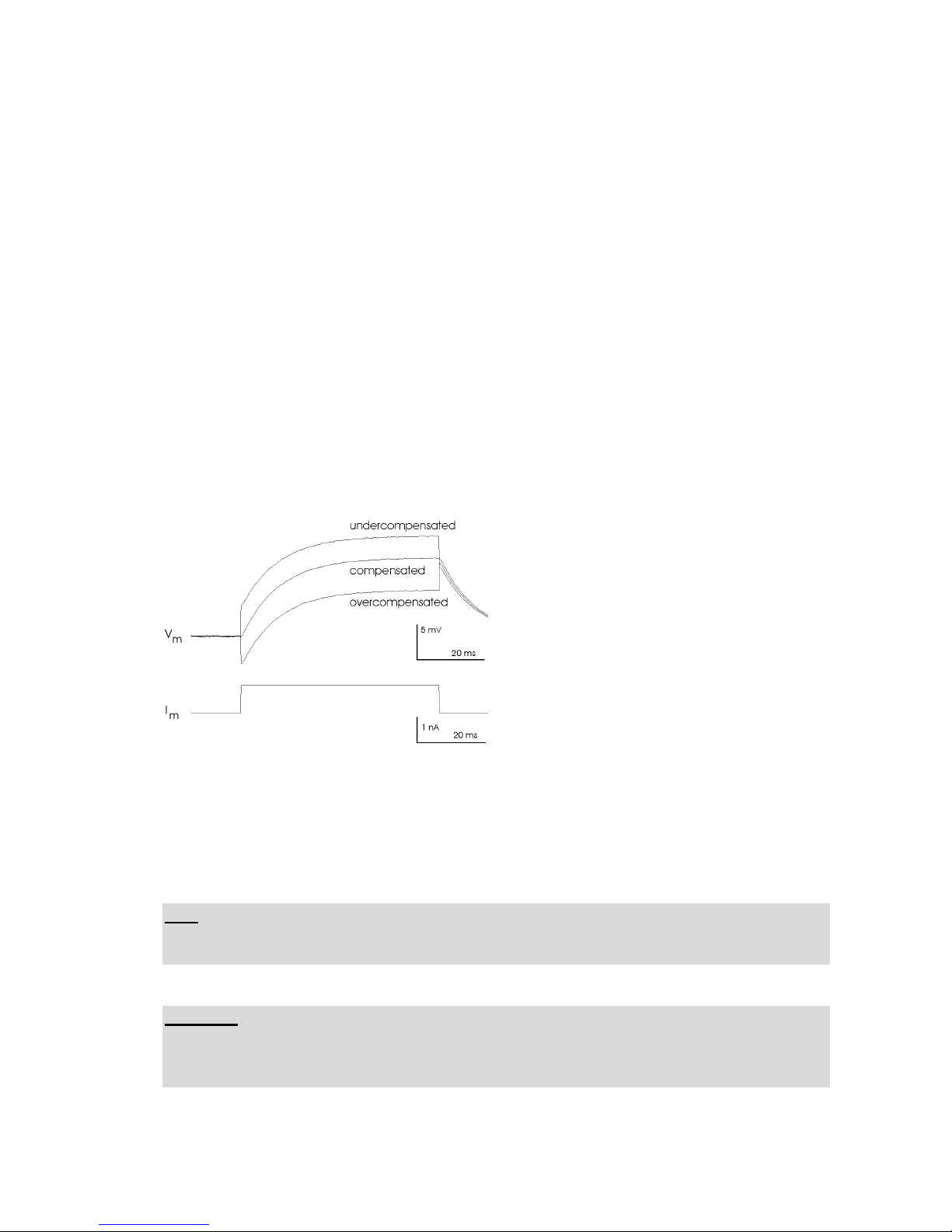
Figure 6: Capacity compensation of the electrode using a model cell (electrode resistance:
100 M, current: 1 nA, cell membrane: 100 M, 100 pF, duty cycle: ¼, switching frequency:
2 kHz). Current stimulus and membrane potential are shown.
Page 56
Tuning Capacity Compensation
Version 1.11 page 8
Second part: fine tuning
Now the basic setting of the CAPACITY COMPENSATION is achieved. Since the electrode
parameters change during the experiment (especially after impaling a cell), it is necessary to
fine tune the CAPACITY COMPENSATION during the experiment using the CAP.COMP.
control on the amplifier. To get familiar with this, connect a cell model and go through the
following steps (the procedure is the identical with a “real” cell).
Connect POTENTIAL OUTPUT and CURRENT OUTPUT (front panel) to another
oscilloscope.
Set SWITCHING FREQUENCY to the desired value (>15 kHz) and DUTY CYCLE to
the desired value.
Set the HOLDING CURRENT to zero. With the amplifier in CC mode, apply square
pulses of a few nA (or a few tens of pA for patch recordings) to the cell. Negative current
pulses are recommended. If you apply positive current pulses, be sure only to elicit ohmic
responses of the cell membrane, i.e. pulses should not elicit openings of voltage gated
channels.
The POTENTIAL OUTPUT should show the ohmic response of the cell membrane,
without an artifact, as illustrated in Figure 6 and Figure 7.
Figure 7: Capacity compensation of the electrode inside a cell. Current stimulus and
membrane potential are shown.
Hint: The results of this procedure look very similar to tuning of the bridge balance. If the
BRIDGE is balanced accurately no differences in the potential outputs should occur when
switching between CC- and BRIDGE mode.
Important: Always monitor the OUTPUT from ELECTRODE POTENTIAL OUTPUT at the
rear panel, using a second oscilloscope. The signals must be always square. If not,
CAPACITY COMPENSATION has to be readjusted or the switching frequency must be
lowered.
Page 57

Tuning Capacity Compensation
Version 1.11 page 9
References:
(1) Polder, H. R., Swandulla, D., Konnerth, A., & Lux, H. D. (1984). An Improved High
Current Single-Electrode Voltage/Current Clamp System. Pflugers Arch. 402, R35.
(2) Polder, H. R., & Swandulla, D. (2001). The use of control theory for the design of voltage
clamp systems: a simple and standardized procedure for evaluating system parameters.
J.Neurosci. Methods 109, 97-109.
(3) Richter, D. W., Pierrefiche, O., Lalley, P. M., & Polder, H. R. (1996). Voltage-clamp
analysis of neurons within deep layers of the brain. J.Neurosci. Methods 67,121-131.
(4) Juusola, M. (1994). Measuring complex admittance and receptor current by single
electrode voltage-clamp. J.Neurosci. Methods 53, 1-6.
(5) Weckstrom M., Kouvaleinen E., & Juusola M. (1992). Measurement of cell impedance in
frequency domain using discontinuous current clamp and white-noise modulated current
injection. Pflugers Arch. 421, 469-472.
(6) Muller, A., Lauven, M., Berkels, R., Dhein, S., Polder, H. R., & Klaus, W. (1999).
Switched single electrode amplifiers allow precise measurement of gap junction conductance.
Amer.J.Physiol. (Cell) 276 (4), C980-C988.
(7) Kapur, A., Yeckel, M. F., Gray, R., & Johnston, D. (1998). L-Type calcium channels are
required for one form of hippocampal mossy fiber LTP. J.Neurophysiol. 79, 2181-2190.
(8) Torkkeli, P. H., Sekizawa, S., & French, A. S. (2001). Inactivation of voltage-activated
Na(+) currents contributes to different adaptation properties of paired mechanosensory
neurons. J.Neurophysiol. 85, 1595-1602.
For more information please contact:
[email protected]
Page 58

SEC/TEC SYSTEMS WITH VCcCC MODE
General Description
The “Voltage Clamp controlled Current Clamp” (VCcCC) or “slow voltage clamp“ (SLOW VC)
mode is used for performing accurate current clamp recordings in the presence of membrane
potential oscillations. The npi single and two electrode current and voltage-clamp amplifiers (npi
SEC 05X/10LX; npi TEC-05X series) have been modified in a way that slow membrane potential
oscillations are exactly controlled by the voltage-clamp module without affecting faster responses,
e.g. postsynaptic potentials (PSPs) and action potentials (APs). The response speed of the voltageclamp feed-back circuit has been decreased by incorporation of electronic circuits with large time
constants (1 - 10000 s). In addition, fast current stimuli (e.g. for conductance measurements) can be
applied through the current clamp input (CURRENT STIMULUS BNC connector).
Operation
The VCcCC mode is controlled through two front panel elements (located in the VC part of the
front panel): a toggle switch marked “on” / “off” and a rotary switch to set the time constants (10100-1000, 5000 and 10000 sec) for the low-pass filter. To start using the VCcCC mode, the
amplifier must be tuned accurately in the fast VC mode (toggle switch “off”). The holding potential
control must be set on the desired value, or a holding potential signal must be provided from an
external device (e.g. a computer). This holding potential will be the preset membrane potential for
the VCcCC mode. Under these conditions, PSPs or other changes of the membrane potential will be
voltage clamped.
If the toggle switch is set “on” the VCcCC mode is started as indicated by the red LED above the
VC LED. Depending on the preset time constant, fast changes of the membrane potential will not
be voltage clamped any more. This is a condition that corresponds to an accurate current clamp.
Fast changes of the membrane potential are monitored on the potential output, slow changes are
compensated by the VCcCC circuit.
The time constant should be selected so that the signals under investigation are not altered by the
VCcCC (please compare with current clamp recordings).
Important: The average membrane potential can be changed only through the VOLTAGE
COMMAND INPUT. If changes are required, please select a short time constant (1 or 10 s).
Note: Please don’t use DHC and VCcCC mode simultaneously!!
Page 59

Current Clamp Input
The current clamp input (CURRENT STIMULUS BNC connector) is connected in the VCcCC
mode in a way that fast current stimuli can be applied to the electrode. The condition for such
recordings is a ratio of >1:1000 between current pulse duration and VCcCC time constant.
Slow (long-lasting) current signals or DC (such as the HOLDING current) will be removed by the
action of the VCcCC system. In the fast VC mode, the current clamp input is disconnected
automatically. In this way, using the VCcCC mode, fast current stimuli can be used, e.g. to monitor
conductance changes.
Literature
1. Peters, F., D. Czesnik, A. Gennerich & D. Schild, (2000) Low frequency voltage clamp:
recording of voltage transients at constant average command voltage, J. Neurosci. Meth. Vol.
99, 129-135.
2. Sutor , B., S. Greiner-Fischer, B. Schlosser (2000) Pharmacologically isolated NMDA-EPSPs
recorded at resting membrane potential of rodent neocortical neurons, Soc. Neurosci. Abstr.,
Vol. 26, Part 1, p 352.
3. Sutor, B., Grimm, C., & Polder, H. R. (2003). Voltage-clamp-controlled current-clamp
recordings from neurons: an electrophysiological technique enabling the detection of fast
potential changes at preset holding potentials. Pflugers Arch. 446, 133-141.
Page 60

SEC/TEC SYSTEMS WITH DHC MODE
General Description
The “Dynamic Hybrid Clamp” (DHC) mode is used for investigations of ionic conductances in
voltage clamp (VC) mode following action potentials in current clamp (CC) mode. In CC mode an
action potential is detected by a spike detector and triggers a timing unit. This timing unit sets a
delay for triggering the SEC/TEC (being in CC mode). The SEC switches from CC mode to VC
mode with the actual membrane potential as holding potential.
Operation
The DHC mode is set through the MODE OF OPERATION switch at the front panel. When the
switch is set to DHC, the amplifier is in CC mode and the membrane potential is fed into a sampleand-hold electronic. If a TTL pulse (+5 V) is applied to the MODE SELECT TTL (SEC-10LX:
DHC TTL) BNC connector, the SEC/TEC is switched to VC mode. The COMMAND INPUT for
voltage clamp is disabled and the command potential is provided by the sample-and-hold electronic
e.g. the command potential represents the last membrane potential before switch to VC mode.
In practice, the investigator needs additionally a spike detector and a timing unit. The spike detector
detects an action potential and triggers – with a delay set by the timing unit – the transition from CC
mode to VC mode.
Note: Please don’t use DHC and VCcCC mode simultaneously!!
Literature
Dietrich, D., Clusmann, H. & Kral, T. (2002). Improved hybrid clamp: resolution of tail currents
following single action potentials. J.Neurosci Meth. 116, 55-63.
Page 61
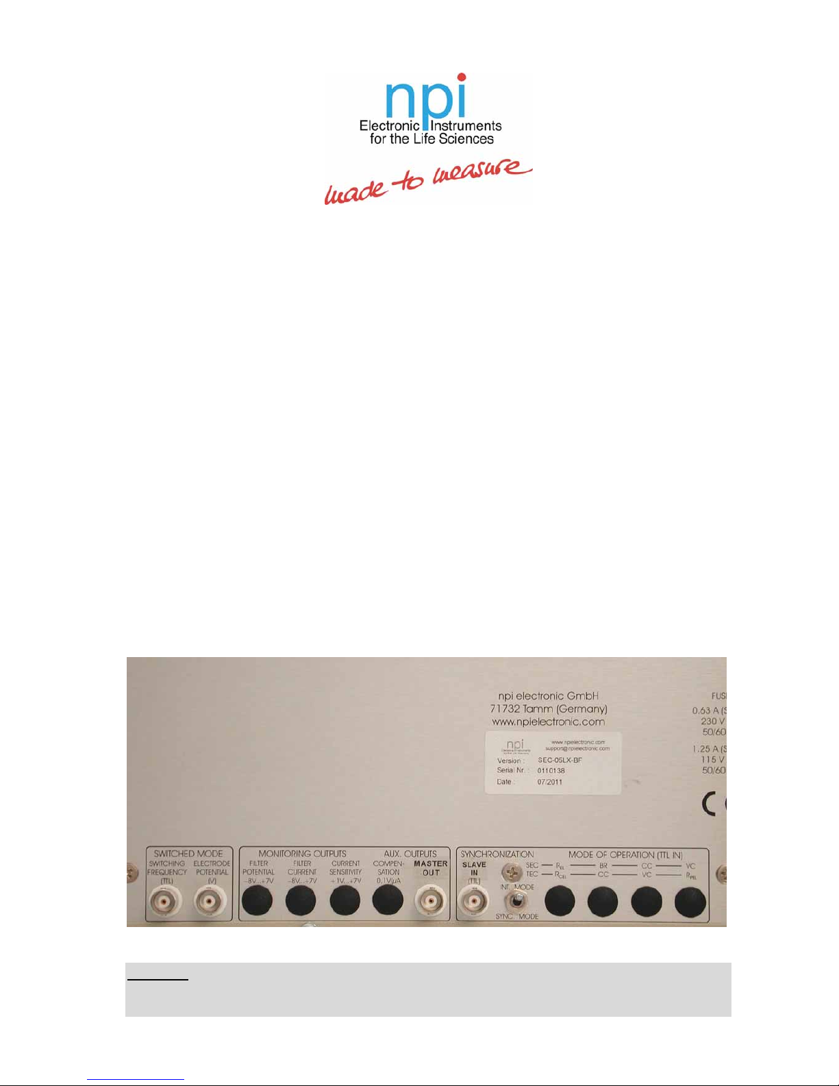
Synchronization of Two or More SEC Amplifier Systems
For recordings with two or more switched mode amplifiers in the same preparation it is
necessary to synchronize the current injection and voltage recording timing protocols to avoid
artifacts and excessive noise. This is done by the SYNCHRONIZATION inputs and outputs at
the rear panel of the instruments based on a "master-slave" arrangement.
The master instrument provides the clock frequency (from which the switching frequency is
generated internally) for the slave instruments.
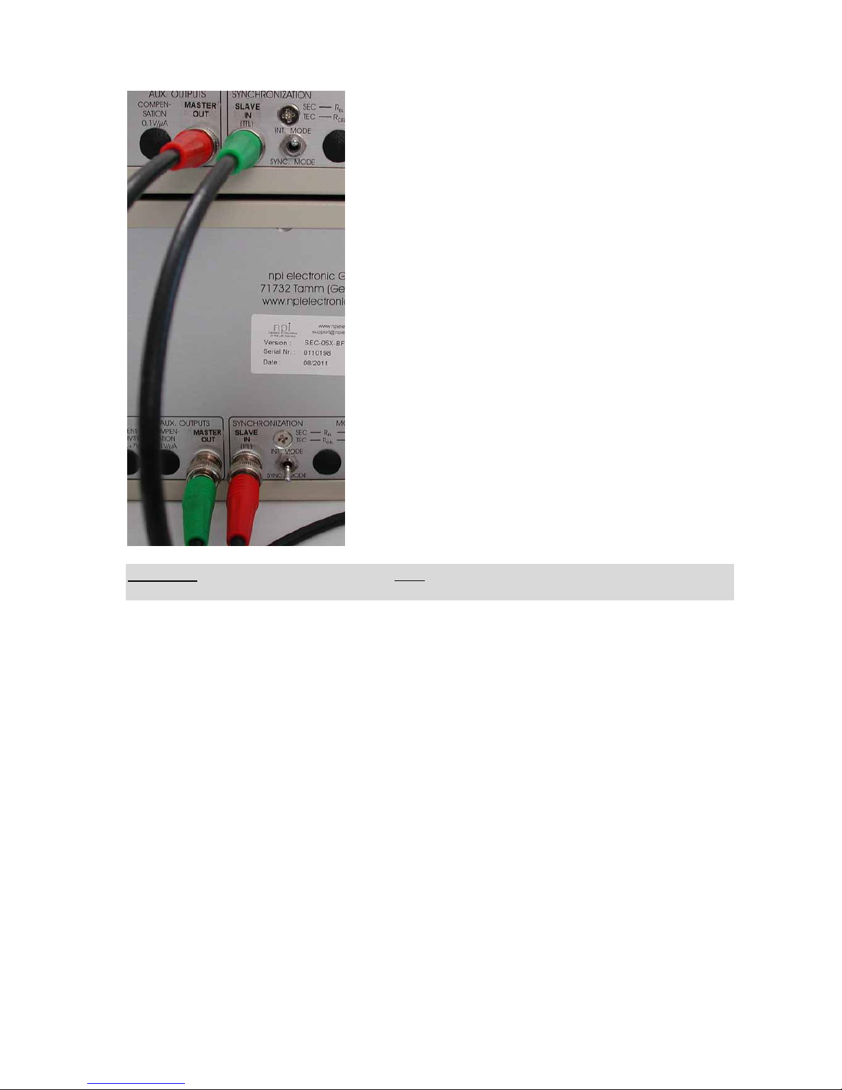
All SEC amplifiers prepared for synchronized operation have a BNC connector marked
MASTER OUT. This output is connected to the SLAVE IN BNC connector slave instrument(s).
Up to four SEC amplifiers can be synchronized, one SEC acting as master and three SEC
operating as slaves.
The position of the toggle switch marked INT. MODE / SYNC. MODE decides whether the
amplifier operates as master or as slave. In the position INT. MODE the switching frequency is
generated internally, and the amplifier operates as master or as stand-alone instrument. In the
position SYNC. MODE the amplifier is used with the clock frequency of the MASTER
instrument, i.e. it works as slave in both switched modes (VC / CC). In this case current injection
and sampling of current and potential signals are synchronous. Therefore, all artifacts are
suppressed.
Warning: If the SYNCHRONIZATION switch is in the SYNC. MODE position and no signal is
connected to the SLAVE IN connector the switched modes of the amplifier (VC and CC) are not
working (no switching frequency!).
Page 62
Important: All synchronized instruments must use the same duty cycle in switched VC or CC
mode! If equipped with LIN mode, the LIN mode must not be enabled!
Literature:
Bedner, P., Niessen, H., Odermatt, B., Willecke, K., & Harz, H. (2003). A method to
determine the relative cAMP permeability of connexin channels. Exp.Cell Res. 291, 25-35.
Dhein, St., Double Cell Voltage Clamp, in: Cardiac Gap Junctions, Karger Verlag, Basel,
1998
Haag, J. and Borst, A. (2002). Dendro-Dendritic Interactions between Motion-Sensitive
Large-Field Neurons in the Fly. J.Neurosci 22 (8), 3227–3233.
Hartveit, E. & Veruki, M. L. (2010). Accurate measurement of junctional conductance
between electrically coupled cells with dual whole-cell voltage-clamp under conditions of
high series resistance. J Neurosci.Methods. 187, 13-25.
Müller, A., M. Bachmann, H.R. Polder, S. Dhein, R. Berkels and W. Klaus (1998)
Measurement of Gap Junction Conductance with Switched Single Electrode Voltage Clamp
Amplifiers. No Effect of Series - and Input Resistance. Pflügers Archiv, 435: R238
Müller, A., M. Lauven, R. Berkels, S. Dhein, H.R. Polder and W. Klaus (1999). Switched
single electrode amplifiers allow precise measurement of gap junction conductance. American
J Physiol. (Cell) 276, C980-C988.
Weng, S., Lauven, M., Schaefer, T., Polontchouk, L., Grover, R. & Dhein, S. (2002)
Pharmacological modification of gap junction coupling by an antiarrhythmic peptide via
protein kinase C activation. FASEB J., 16, 1114-1116.
Page 63

CALIBRATION of the x0.1 RANGE
LOW VOLTAGE / LOW NOISE HEADSTAGE
(Standard SEC SYSTEMS without
Adapted Amplifier)
This headstage has an output current range of 15nA into maximum 100 M, and the noise and bias current
are reduced by a factor of 10 compared to the standard headstage. Therefore, it is recommended for whole
cell patch clamp recordings.
All current related signals have to be divided/multiplied by 10.
CURRENT DISPLAY: XXX pA /no decimal point (100 = 100 pA)
HOLDING CURRENT: XXX pA (100 = 100 pA)
Input sensitivity: BNC labeled 1 nA/V has now 0.1 nA/V i.e. 1V = 100 pA
BNC labeled 0.1 nA/V has now 0.01 nA/V i.e. 1V = 10 pA)
Output sensitivity: 1V/nA-100V/nA
BRIDGE BALANCE: (XXX) x10 M
R
EL
mode display: XXXX M (i.e. 10 is 100 M)
The potential input and output signals are not
affected.
Page 64

CALIBRATION of the x0.1 RANGE
LOW VOLTAGE / LOW NOISE HEADSTAGE
(SEC SYSTEMS with Adapted Amplifier)
This headstage has an output current range of 15nA into maximum 100 M, and the noise and bias current
are reduced by a factor of 10 compared to the standard headstage. Therefore, it is recommended for whole
cell patch clamp recordings.
Current related signals:
CURRENT DISPLAY: X.XXX pA (100 = 100 pA)
HOLDING CURRENT: X.XX nA (100 = 1 nA)
Input sensitivity: BNC labeled 1 nA/V i.e. 1V = 1nA
BNC labeled 0.1 nA/V. 1V = 100 pA)
Output sensitivity: 1V/nA-100V/nA, with 1 V/nA (= 1 mV/pA) 100 pA is 100 mV.
BRIDGE BALANCE: standard as indicated at the front panel (100 = 100 M)
R
EL
mode display: standard as indicated at the front panel (100 = 100 M)
The potential input and output signals are not affected.
Page 65

Calibration of TEC-05X Amplifier with x10 Headstage
GENERAL: The current range of the x10 low voltage headstage is the following:
1.2 µA into 10 M (max. output voltage is 12 V)
All current related inputs and outputs must be multiplied by a factor of ten.
This is valid for all four modes of operation (R
EL
, BR, CC, VC)
Potential related signals are not affected.
CURRENT STIMULUS INPUT: 1 nA/V: corresponds 10 nA/V
HOLDING: XX.X nA (max. 99.9 nA)
CURRENT OUTPUT SENSITIVITY: 0.1 V/nA corresponds 0.01 V/nA
0.2 V/nA corresponds 0.02 V/nA
0.5 V/nA corresponds 0.05 V/nA
1 V/nA corresponds 0.1 V/nA
2 V/nA corresponds 0.2 V/nA
5 V/nA corresponds 0.5V/nA
10 V/nA corresponds 1 V/nA
CURRENT DISPLAY: shows current divided by ten (XX.X nA)
10.0 corresponds to 100 nA
Maximum shown is 199 nA
BRIDGE BALANCE:
Switch in 100 M position: XXX M (050 corresponds 5 M), Maximum is 99.9 M
Switch in 10 M position: XXX M (050 corresponds 0.5 M), Maximum is 9.9 M
ELECTR. RESISTANCE DISPLAY: shows electrode resistance multiplied by ten XXX M (050
corresponds 5 M), Maximum is 199 M
Important: If high-resistance electrodes are used the capacity compensation must be set properly for
exact determination of REL.
Example: HOLDING CURRENT: 100 corresponds to 10 nA, the DISPLAY will show 01.0 nA
INPUT at 1V/nA BNC: 1V corresponds to 10 nA, the DISPLAY will show 01.0 nA
voltage at CURRENT OUTPUT is then
CURRENT OUTPUT SENSITIVITY 0.1V/nA: 0.1V
CURRENT OUTPUT SENSITIVITY 1 V/nA: 1V
CURRENT OUTPUT SENSITIVITY 10 V/nA: 10V
Page 66

SEC-EXT Headstage for Extracellular Recordings
with npi SEC Systems
The SEC-EXT headstage extends the range of operation of SEC amplifiers to the field of extracellular
recordings. It has a differential high impedance input stage with capacity compensation for the noninverting input (+ INPUT) and a gain of ten. This input stage is followed by a high pass filter with six
corner frequencies (1; 3; 10; 30; 100; 300 Hz).
DC output (POTENTIAL OUTPUT of the SEC): The direct output is connected to the
"POTENTIAL" channel of the SEC system, i.e. the signal is passed through the OFFSET
compensation stage, magnified by ten and filtered by the POTENTIAL FILTER. The overall gain
for the DC output is 100 (x10 input stage, x10 SEC potential magnification).
AC output (high pass output, CURRENT OUTPUT of the SEC): The output of the high pass filter
stage is fed into the "CURRENT" channel of the SEC system, i.e. it is passed through the
CURRENT OUTPUT SENSITIVITY stage where it is amplified (overall gains 10; 20; 50; 100;
200; 500; 1000). The amplified signal is filtered by the CURRENT FILTER.
Important: The SEC system must be in BRIDGE (B) mode. All inputs must be turned off or
disconnected. The BRIDGE balance control must be on 000 to avoid incoming disturbances.
The following systems and front panel elements are working:
CAP. COMPENSATION Capacity compensation control for the non-inverting (+) input
POTENTIAL OUTPUT DC output (x100)
OFFSET Offset control for the DC output
POTENTIAL FILTER Low pass Bessel filter for the DC output
POTENTIAL DISPLAY Shows electrode potential x10 (100 are 10 mV)
CURRENT OUTPUT AC (high pass) output (x10...x1000)
CUR. OUTPUT Gain stage (10-1000) for the AC output
SENSITIVITY
CURRENT FILTER Low pass Bessel filter for the AC output
OSCILLATION as described in the SEC manual
SHUTOFF
PENETRATION "BUZZ" as described in the SEC manual (+I
max
/-I
max
do not work)
Important: This headstage is sensitive to static discharges. It is equipped with very sensitive FET
amplifiers, which can be damaged with electrostatic charge and must therefore be handled with care.
Damage can be avoided by touching a grounded metal surface when changing or adjusting the
electrodes. If a headstage is not used the input should always be connected to ground (either using an
appropriate connector or with aluminum foil wrapped around the headstage). Always turn power off
when connecting or disconnecting headstages from the 19" cabinet.
Page 67

SEC SYSTEMS WITH LINEAR (x1 AND x10) MODE
General Description
The linear mode of the SEC amplifier is an “unswitched” operation mode of the SEC, working in
voltage clamp (VC) and current clamp (CC). In contrast to standard patch clamp amplifiers the
electrode voltage is nevertheless measured, also in VC. However, due to current flow during voltage
measurement, this measurement is distorted by the series resistance. This is the reason why the linear
mode should be used only for recordings where only little current flows.
In the linear mode the background noise of the amplifier is substantially reduced. Therefore, the linear
mode is predestined for low-noise recordings in VC and CC mode.
The linear mode allows also loose-patch or macro-patch recordings, and can be used to approach the
cell and form a gigaseal in VC mode.
The LIN x10 mode can be used for iontophoresis or electroporation, i.e. juxtacellular, non-invasive
filling of cells with or single cell transfection with DNA. The stimulus amplitude range in CC or
BRIDGE mode is also enhanced to max. ±120 nA.
Operation
The linear mode is set through the Linear Mode switch at the front panel. When the switch is set to the
middle position, the amplifier is in “switched” (VC or CC) or in BRIDGE mode (CC). Setting the
switch to x1 or x10 lets the amplifier work in linear mode either without or with x10 amplification.
Linear Mode - x1/x10 switch
x1: The amplifier operates in linear, unswitched mode (see below), current and/or
voltage are not enhanced. LIN LED lights green.
x10: The amplifier operates in linear electroporation mode. Command voltage in VC or
current stimulus in CC or BRIDGE mode are multiplied by the factor of ten. This
allows to apply stimuli of max. ±120 nA. In this operation mode the LIN LED lights
red and the voltage output at POTENTIAL OUTPUT x10mV BNC connector is set
to x1mV.
middle: In the middle position of this switch the amplifier works in switched or BRIDGE
mode. The LIN LED does not light.
Important: In LIN x10, the voltage output (POTENTIAL OUTPUT x10 mV BNC connector) is set to
x1 mV, i.e. 1 V is 1 V (and not 100 mV as in LIN mode x1).
Important: The linear mode must be used with low resistance patch pipettes only! Ringing can be
avoided by setting the GAIN in VC mode not higher than 1 and by setting the capacity compensation
of the electrode to very low values (best close to zero).
Note: Be always aware, that the linear mode introduces a series resistance error that is dependent on
the magnitude of series resistance and current that flows during measurement.
Important: The LIN mode x1 or x10 must not be used if two SEC amplifiers work in synchronized
(Master/Slave) configuration.
Important: BRIDGE balance and Capacity Compensation work in LIN mode and can be used to
minimize artifacts during electroporation.
Page 68

SEC SYSTEMS WITH SERIES RESISTANCE
COMPENSATION
The SERIES RESISTANCE COMPENSATION (RS compensation) unit consist of SERIES
RESISTANCE COMP. potentiometer, and RS ON switch.
The RS compensation unit is functional if the LINEAR VC MODE is activated. It is not
effective in all other modes of the amplifier.
SER. RES. COMP. potentiometer and switch
Potentiometer for setting the compensation for the SERIES RESISTANCE
(Linear VC mode) in percent of the resistance value that is set at the
BRIDGE BALANCE potentiometer. Therefore, it is important to set the
BRIDGE BALANCE correctly before using the series resistance
compensation.
Very Important: When using the SERIES RESISTANCE compensation do not use the
potential values recorded from the POTENTIAL OUTPUT (mV) BNC connector or the value
shown at the POTENTIAL display as a measure for the membrane potential, since these
values include also the additional voltage generated by SERIES RESISTANCE COMP. for
compensation of the voltage drop at the SERIES RESISTANCE.
For instance, for calculating I/V curves do not use the potential values recorded from the
POTENTIAL OUTPUT (x10 mV) BNC connector. Use the COMMAND + HOLDING
potential instead.
RS COMP. switch
Switch for activating the SERIES RESISTANCE COMPENSATION circuit.
BASIC SETTINGS
Before using the LIN Mode the amplifier should be used in BRIDGE mode to set the
CAPACITY COMPENSATION and BRIDGE BALANCE as good as possible.
Very Important: When using the LIN VC MODE the CC coarse capacity compensation at
the headstage must be set to zero.
Page 69

The CAPACITY COMPENSATION control on the front panel can be used to improve the
speed of response, it has also an impact on the stability of the feedback circuit. When starting
the LIN VC session this control should be on a low value.
The VC GAIN and INTEGRATOR controls have the same function as in switched VC mode.
When starting the LIN VC session the GAIN control should be on a low value,
INTEGRATOR turned OFF.
Functional description
The series resistance compensation unit is designed to compensate errors induced by the
access resistance during whole cell voltage clamp recordings. It is optimized for access
resistances of below 20 M ( the lower the value the better).
The compensation is based on a shift of the command potential to counterbalance the access
resistance artifact caused by the current flow during the VC recording. It is with respect to the
VC control a positive feedback loop and can cause oscillations if set too high. The maximum
compensation is 90%, in real experiments it is often lower due to uncompensated stray
capacities and nonlinearities of the microelectrode.
For current clamp recordings the amplifier is equipped with a BRIDGE balance circuit which
can fully compensate the access resistance by subtraction of a current proportional voltage
from the recorded electrode signals. In this way the correct membrane potential is displayed
during current injecting protocols. The setting of the BRIDGE balance control depicts the
value of the access resistance in M.
The RS compensation is based on the setting of the BRIDGE balance control. The current
signal recorded by the amplifier is fed via the BRIDGE Balance control into the RS
compensation control, the signal generated from the RS compensation control is summed with
the COMMAND signal and shifts the clamp potential so that the error induced on the access
resistance is reduced.
Important hints
RS compensation works correctly ONLY in LINEAR VC operating mode.
Set the BRIDGE BALANCE correctly before using RS compensation.
Turn coarse capacity compensation at the headstage to ZERO. CAPACITY
COMPENSATION control on the front panel may be used with care.
Integrator and gain are functional with RS compensation
 Loading...