


OPERATING INSTRUCTIONS AND
SYSTEM DESCRIPTION FOR THE
EXT-16DX
EXTRACELLULAR AMPLIFIER
VERSION 1.3
npi 2013
npi electronic GmbH, Bauhofring 16, D-71732 Tamm, Germany
Phone +49 (0)7141-9730230; Fax: +49 (0)7141-9730240
support@npielectronic.com; http://www.npielectronic.com

EXT-16DX User Manual
_______________________________________________________________________________________________________________
___________________________________________________________________________
version 1.3 page 2
Table of Contents
1. Safety Regulations............................................................................................................ 3
2. EXT-16DX....................................................................................................................... 4
2.1. System Description...................................................................................................... 4
2.2. Signal Flow Diagram................................................................................................... 4
2.3. Description of the Front Panel..................................................................................... 5
2.4. Description of the Rear Panel...................................................................................... 7
2.5. Headstages................................................................................................................... 9
Headstage Assembly Elements.................................................................................... 9
3. Literature.......................................................................................................................... 12
4. Technical Data.................................................................................................................. 13

EXT-16DX User Manual
_______________________________________________________________________________________________________________
___________________________________________________________________________
version 1.3 page 3
1. Safety Regulations
VERY IMPORTANT: Instruments and components supplied by npi electronic are NOT
intended for clinical use or medical purposes (e.g. for diagnosis or treatment of
humans), or for any other life-supporting system. npi electronic disclaims any
warranties for such purpose. Equipment supplied by npi electronic must be operated
only by selected, trained and adequately instructed personnel. For details please consult
the GENERAL TERMS OF DELIVERY AND CONDITIONS OF BUSINESS of npi
electronic, D-71732 Tamm, Germany.
1) GENERAL: This system is designed for use in scientific laboratories and must be
operated by trained staff only. General safety regulations for operating electrical devices
should be followed.
2) AC MAINS CONNECTION: While working with the npi systems, always adhere to the
appropriate safety measures for handling electronic devices. Before using any device
please read manuals and instructions carefully.
The device is to be operated only at 115/230 Volt 60/50 Hz AC. Please check for
appropriate line voltage before connecting any system to mains.
Always use a three-wire line cord and a mains power-plug with a protection contact
connected to ground (protective earth).
Before opening the cabinet, unplug the instrument.
Unplug the instrument when replacing the fuse or changing line voltage. Replace fuse
only with an appropriate specified type.
3) STATIC ELECTRICITY: Electronic equipment is sensitive to static discharges. Some
devices such as sensor inputs are equipped with very sensitive FET amplifiers, which can
be damaged by electrostatic charge and must therefore be handled with care. Electrostatic
discharge can be avoided by touching a grounded metal surface when changing or
adjusting sensors. Always turn power off when adding or removing modules,
connecting or disconnecting sensors, headstages or other components from the
instrument or 19” cabinet.
4) TEMPERATURE DRIFT / WARM-UP TIME: All analog electronic systems are
sensitive to temperature changes. Therefore, all electronic instruments containing analog
circuits should be used only in a warmed-up condition (i.e. after internal temperature has
reached steady-state values). In most cases a warm-up period of 20-30 minutes is
sufficient.
5) HANDLING: Please protect the device from moisture, heat, radiation and corrosive
chemicals.

EXT-16DX User Manual
_______________________________________________________________________________________________________________
___________________________________________________________________________
version 1.3 page 4
2. EXT-16DX
2.1. System Description
The EXT-16DX is an extracellular amplifier with up to 16 channels to be operated in singleended or referenced (differential) configuration. In referenced configuration one of the
electrodes can be selected to function as reference for all other electrodes. All channels are
equipped with highpass filter, lowpass filter and gain. Corner frequencies and gain are
customized and the same for each channel. Digital displays show the selected corner
frequencies and gain. These displays can be dimmed for use of the amplifier combined with
fluorescence measurements.
The recorded signals are available at BNC connectors and an SCSI connector (option) for
direct connection to a data acquisition board. They are also linked to a SubD connector for
connecting the optional R/I-T1DX for electrode resistance measurement and current injection.
The EXT-16DX can be operated manually by the controls at the front panel or remotely by a
digital I/O board (option)
An external power supply (PWR-03DX) guarantees low noise operation.
2.2. Signal Flow Diagram
The signal is passed through the EXT-16DX as shown below.
Figure 1: EXT-16DX signal flow (shown for one channel only)
The extracellular signal is linked from the headstage to +IN of the differential input. –In is
either the signal from the reference electrode or GND depending on the setting of switch #2,
Figure 2. The difference is then passed through highpass filter, gain and lowpass filter and
linked to the output (BNC connector or SCSI/SubD connector).

EXT-16DX User Manual
_______________________________________________________________________________________________________________
___________________________________________________________________________
version 1.3 page 5
2.3. Description of the Front Panel
Figure 2: EXT-16DX front panel view
In the following description of the front panel elements each element has a number that is
related to that in Figure 2. The number is followed by the name (in uppercase letters) written
on the front panel and the type of the element (in lowercase letters). Then, a short description
of the element is given.
(1) REMOTE / MANUAL switch
Switch for selecting manual operation by the controls at the front panel or remote operation
by a digital I/O board. This switch is functional only if the remote control option is installed.
(2) REFERENCED / SINGLE ENDED switch
Switch to select recording either in referenced or in single ended mode. In SINGLE ENDED
mode recording with up to 16 electrodes with reference to ground is possible. In
REFERENCED mode the signal of the reference electrode is subtracted from the recording
electrode resulting in reduction of noise. The electrode acting as reference is selected by
switch #11. The signal of the reference electrode can be recorded at the respective BNC
connector at the rear panel in phase (see also below)
Important: When selecting REFERENCED mode the channel acting as reference must not be
left open. The amplifier is in an undefined state, if the reference channel is left open, and can
go into saturation making reliable measurements impossible.
(3) CHANNEL display
Display indicating the CHANNEL (electrode) that is selected for reference (0..15). In single
ended mode SE is displayed.
(4) HIGHPASS display
Display showing the value of the selected corner frequency for the highpass filter. Possible
corner frequencies: DC, 0.1, 0.3, 0.5, 1, 3, 5, 10, 30, 50, 100, 300, 500, 800, 1k, 3k Hz.

EXT-16DX User Manual
_______________________________________________________________________________________________________________
___________________________________________________________________________
version 1.3 page 6
(5) GAIN display
Display showing the value of the selected amplification of the recorded signal. Possible
factors: 10, 20, 50, 100, 200, 500, 1k, 2k, 5k, 10k.
(6) LOWPASS display
Display showing the value of the selected corner frequency for the lowpass filter. Possible
corner frequencies: 20, 50, 100, 200, 300, 500, 700, 1k, 1,3k, 2k, 3k, 5k, 8k, 10k, 13k, 20k
Hz.
(7) BRIGHTNESS ADJUST potentiometer
Potentiometer for dimming the displays, e.g. during fluorescence measurements. In OFF
position all displays and LEDs are switched off, except the decimal point of display #4 that
indicates that the amplifier is still powered on.
(8) LOWPASS SELECT switch
Rotary switch for choosing the corner frequency for the lowpass filter. The selected corner
frequency is shown at display #6.
(9) GAIN SELECT switch
Rotary switch for choosing the amplification factor (gain) for the extracellular signal. The
selected gain is shown at display #5.
(10) HIGHPASS SELECT switch
Rotary switch for choosing the corner frequency for the highpass filter. The selected corner
frequency is shown at display #4.
(11) CHANNEL SELECT switch
Rotary switch for choosing the electrode (channel) to function as reference. The selected
channel is shown at display #3.
(12) HEADSTAGE CON 1 connector
Connector for connecting the recording headstage.
(13) GROUND connector
Connector providing system ground.

EXT-16DX User Manual
_______________________________________________________________________________________________________________
___________________________________________________________________________
version 1.3 page 7
2.4. Description of the Rear Panel
Figure 3: EXT-16DX rear panel view
The following connectors are located at the rear panel.
(1) PC INTERFACE connector (optional)
Male SCSI connector for attaching a data acquisition board, e.g. from National Instruments or
Data Translation.
(2) IO R/I-T1DX connector
SubD connector for connecting a R/I-T1M electrode resistance test/current injection device.
(3) AUX connector (optional)
Customized auxiliary connector.
(4) AUX connector (optional)
Customized auxiliary connector.
(5) AUX connector (optional)
Customized auxiliary connector.
(6) POWER SUPPLY connector
Connector for npi power supply PWR-03DX.
Note: This power supply is must be used with one npi EXT-16DX system only.
(7) CHASSIS connector
Connector for grounding the cabinet.
(8) GROUND connector
Connector providing system ground.

EXT-16DX User Manual
_______________________________________________________________________________________________________________
___________________________________________________________________________
version 1.3 page 8
MONITORING UNIT
The monitoring unit shows the selected channel, gain or corner frequency as a DC voltage.
(9) CHANNEL monitor connector
BNC connector providing the monitor signal for the selected channel for reference
(range: -8V…+7V) , e.g. channel 0 is monitored by –8 V or channel 9 is monitored by +1V.
In single ended mode the monitor output is +9V.
(10) HIGHPASS monitor connector
BNC connector providing the monitor signal for the selected corner frequency of the highpass
filter (range: +-8V…+7V).
(11) GAIN monitor connector
BNC connector providing the monitor signal for the selected gain (range: +1V…+10V).
(12) LOWPASS monitor connector
BNC connector providing the monitor signal for the selected corner frequency of the lowpass
filter (range: -8V…+7V).
(13) OUT connectors
BNC connectors providing the extracellular recorded signal. The signal is filtered with the
selected corner frequencies and amplified with the selected gain. In referenced recording
mode one channel shows the reference voltage.
Important: The signal of the reference electrode at the OUT connector is filter and amplified
as well. In contrast, the difference between signal at the recording electrode and signal at the
reference electrode is formed from the raw signals. The raw signals are not available.
EXT-16DX User Manual
_______________________________________________________________________________________________________________
___________________________________________________________________________
version 1.3 page 9
2.5. Headstages
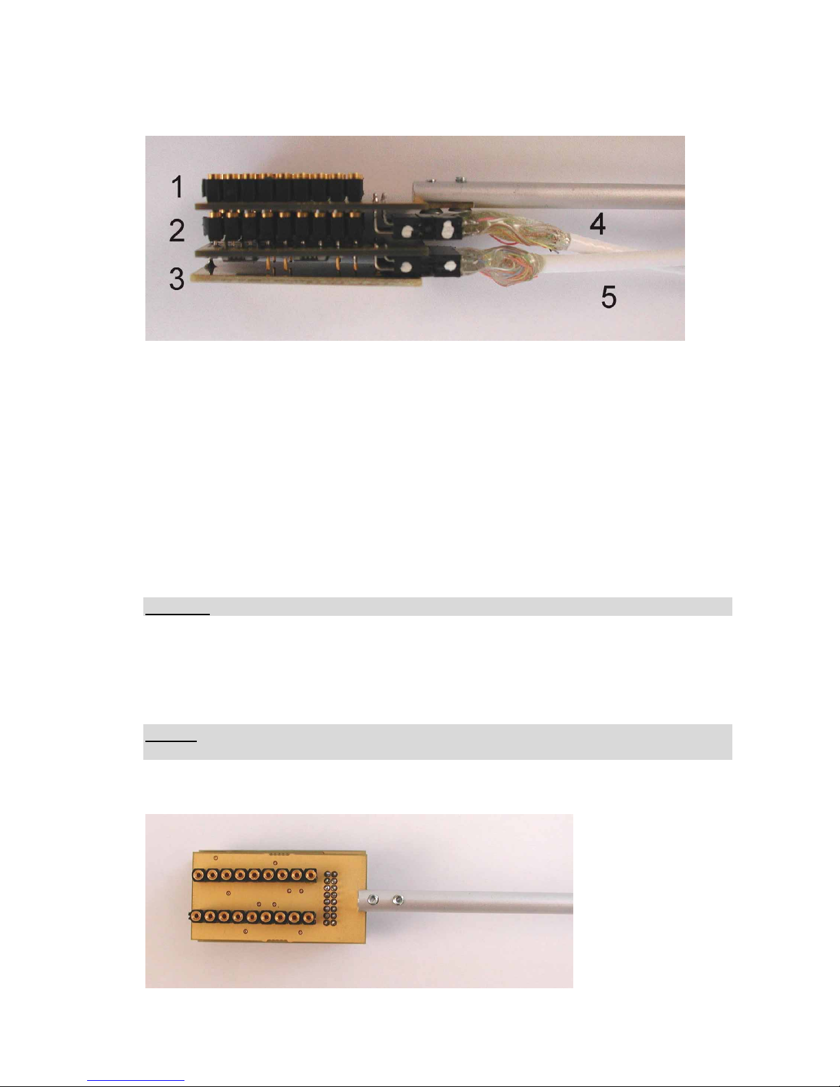
Figure 4: headstage assembly for EXT-16DX and R/I-T1DX
Headstage Assembly Elements
1 stimulation headstage (EXT-MINI-RI-16-DIL)
2 recording headstage with electrode connector for Neuronexus electrode (EXT-MINI-
SE-16-DIL)
3 shield
4 cable to R/I-T1DX (green connector)
5 cable to EXT-16DX (blue connector)
Important: The cables must be connected so that the white labels fit!
The recording headstage is attached to the EXT-16DX amplifier (HEADSTAGE CON 1
connector, blue). The stimulation headstage is connected to the R/I-T1DX (HEADSTAGE
CON 2 connector, green). The recording headstage has also a connector for a Neuronexus
electrode (standard A-series probe package, 16 channels).
Caution: The headstage is sensitive to electrostatic discharge and must be handled with care.
Always ground yourself when touching the headstage.
Figure 5: headstage assembly top view

EXT-16DX User Manual
_______________________________________________________________________________________________________________
___________________________________________________________________________
version 1.3 page 10
Figure 6: headstage assembly with NeuroNexus electrode
Figure 7: side view of the headstage assembly with cables connected
Important: The cables must be connected so that the white labels fit!
Figure 8 shows a schematic of the top view of the headstage assembly with the connector for
the test array or the NeuroNexus electrode, respectively.
The test array is for testing purposes only. It consists of resistors (1 M) mimics the unit of
the NeuroNexus electrode. The two plugs (0.5 mm diameter) next to the connector of the
cable are labeled by a point (orientation label). They provide system ground and should be
used to ground the preparation.
Figure 8: positioning of the test array on top of the headstage assembly (top view)

EXT-16DX User Manual
_______________________________________________________________________________________________________________
___________________________________________________________________________
version 1.3 page 11
The NeuroNexus electrode has only 8 pairs of connectors for 16 recording/stimulation sites
and is plugged into the headstage as shown in Figure 9. The 9th pair next to the cable
connector (GND) is left open since the electrode has no sites for grounding.
Note: If the test array is plugged-in with a wrong orientation, nothing will be damaged, but
some electrodes are short-circuited and others show 2 M instead of 1 M resistance when
using the electrode resistance test (with R/I-T1DX).
Figure 9: positioning of the NeuroNexus electrode on top of the headstage assembly (top
view)
Note: Recording/stimulation site numbering at the headstage and NeuroNexus electrode is 1
to 16. Recording/stimulation site numbering at the amplifier is 0 to 15.

EXT-16DX User Manual
_______________________________________________________________________________________________________________
___________________________________________________________________________
version 1.3 page 12
3. Literature
o Barmashenko, G., Eysel, U. T., & Mittmann, T. (2003). Changes in intracellular calcium
transients and LTP in the surround of visual cortex lesions in rats. Brain Res. 990, 120-
128.
o Boulton, A. A., Baker, G. B. & Vanderwolf, C. H. (eds.) (1990). Neurophysiological
Techniques, Basic Methods and Concepts. Humana Press, Clifton, New Jersey.
o Huemmeke, M., Eysel, U. T., & Mittmann, T. (2002). Metabotropic glutamate receptors
mediate expression of LTP in slices of rat visual cortex. Eur.J.Neurosci. 15, 1641-1645.
o Huemmeke, M., Eysel, U. T., & Mittmann, T. (2004). Lesion-induced enhancement of
LTP in rat visual cortex is mediated by NMDA receptors containing the NR2B subunit. J
Physiol 559 , 875-882.
o Schulz, D., Huston, J. P., Jezek, K., Haas, H. L., Roth-Harer, A., Selbach, O., & Luhmann,
H. J. (2002). Water maze performance, exploratory activity, inhibitory avoidance and
hippocampal plasticity in aged superior and inferior learners. Eur.J.Neurosci. 16, 2175-
2185.
o Kettenmann, H. & Grantyn, R. (eds.) (1992). Practical Electrophysiological Methods.
Wiley-Liss, New York
o Kowski, A. B., Veh, R. W., & Weiss, T. (2009). Dopaminergic activation excites rat lateral
habenular neurons in vivo. Neuroscience. 161, 1154-1165.
o Lalley, P.M., A.K. Moschovakis and U. Windhorst (1999) Electrical Activity of Individual
Neurons In Situ: Extra- and Intracellular Recording, in: U. Windhorst and H. Johansson
(eds.) Modern Techniques in Neuroscience Research, Springer, Berlin, New York.
o Lambert, F. M., Beck, J. C., Baker, R., & Straka, H. (2008). Semicircular canal size
determines the developmental onset of angular vestibuloocular reflexes in larval Xenopus.
Journal of Neuroscience 28, 8086-8095.
o Meuth, S. G., Aller, M. I., Munsch, T., Schuhmacher, T., Seidenbecher, T., Meuth, P.,
Kleinschnitz, C., Pape, H. C., Wiendl, H., Wisden, W., & Budde, T. (2006). The
contribution of TASK-1-containing channels to the function of dorsal lateral geniculate
thalamocortical relay neurons. Molecular Pharmacology.
o Müller, Ch.M. (1992) Extra- and Intracellular Recording in the Slice, in: Kettenmann, H.
& Grantyn, R. (eds.) Practical Electro-physiological Methods, Wiley-Liss, New York
o Ogden, D. (ed.) (1992) Microelectrode Techniques - The Plymouth Workshop Handbook,
Second Edition, The Company of Biologists Ltd., Cambridge
o Schneider, N. L. & Stengl, M. (2006). Gap junctions between accessory medulla neurons
appear to synchronize circadian clock cells of the cockroach Leucophaea maderae. J
Neurophysiol. 95, 1996-2002.
o Seidenbecher, T. and H.C. Pape (2001) Contribution of intralaminar thalamic nuclei to
spike-and-wave-discharges during spontaneous seizures in a genetic rat model of absence
epilepsy, European Journal of Neuroscience, Vol. 13:1537-1546
o Windhorst, U. and H. Johansson (eds.) (1999) Modern Techniques in Neuroscience
Research, Springer, Berlin, Heidelberg, New York

EXT-16DX User Manual
_______________________________________________________________________________________________________________
___________________________________________________________________________
version 1.3 page 13
4. Technical Data
Input: >1012 , range ±2 V
Differential Input: CMR >70 dB at 1 kHz (tested with 0 input resistance)
Input Capacitance: 10 pF
CHANNEL Monitor: -8V…+7V; +13V in single ended mode
HIGHPASS Filter: single pole, attenuation: -6 dB / octave, corner frequencies (Hz):
DC, 0.1, 0.3, 0.5, 1, 3, 5, 10, 30, 50, 100, 300, 500, 800, 1k, 3k;
selected by rotary switch
HIGHPASS Monitor: -8V…+7V
LOWPASS Filter: single pole, attenuation: -6 dB/octave, corner frequencies (Hz): 20,
50, 100, 200, 300, 500, 700, 1k, 1,3k, 2k, 3k, 5k, 8k, 10k, 13k, 20k;
selected by rotary switch
LOWPASS Monitor: -8V…+7V
GAIN: 10, 20, 50, 100, 200, 500, 1k, 2k, 5k, 10k; selected by rotary switch
GAIN Monitor: +1V…+10V
Output: range: ±10 V into 1 k / ±1 V into 50
External power supply : 115/230 Volt AC, 60/50 Hz, fuse 1.6/0.8 A, slow
Dimensions: 19” rackmount cabinet
19” (483 mm), 10” (250 mm), 3.5” (88 mm)
Headstage
Headstage Size: without housing, approx. 40 mm x 18 mm, with holding bar
 Loading...