

Page 1
OPERATING INSTRUCTIONS AND
SYSTEM DESCRIPTION FOR THE
EXT-02F
EXTRACELLULAR AMPLIFIER
WITH FILTERS
One or Two Channel Recordings
VERSION 1.0
npi 2006
npi electronic GmbH, Hauptstrasse 96, D-71732 Tamm, Germany
Phone +49 (0)7141-9730230; Fax: +49 (0)7141-9730240
[email protected]; http://www.npielectronic.com
Page 2

EXT-02F User Manual
________________________________________________________________________________________________________________
___________________________________________________________________________
version 1.0 page 2
Table of Contents
1. Safety Regulations ..............................................................................................................3
2. EXT-02F .............................................................................................................................4
2.1. Components.................................................................................................................4
2.2. System Description...................................................................................................... 4
2.3. Description of the Front Panel..................................................................................... 4
2.4. Description of the Rear Panel...................................................................................... 7
3. Technical Data ....................................................................................................................8
Page 3

EXT-02F User Manual
________________________________________________________________________________________________________________
___________________________________________________________________________
version 1.0 page 3
1. Safety Regulations
VERY IMPORTANT
: Instruments and components supplied by npi electronic are NOT
intended for clinical use or medical purposes (e.g. for diagnosis or treatment of
humans), or for any other life-supporting system. npi electronic disclaims any
warranties for such purpose. Equipment supplied by npi electronic must be operated
only by selected, trained and adequately instructed personnel. For details please consult
the GENERAL TERMS OF DELIVERY AND CONDITIONS OF BUSINESS of npi
electronic, D-71732 Tamm, Germany.
1) GENERAL: This system is designed for use in scientific laboratories and must be
operated by trained staff only. General safety regulations for operating electrical devices
should be followed.
2) AC MAINS CONNECTION: While working with the npi systems, always adhere to the
appropriate safety measures for handling electronic devices. Before using any device
please read manuals and instructions carefully.
The device is to be operated only at 115/230 Volt 60/50 Hz AC. Please check for
appropriate line voltage before connecting any system to mains.
Always use a three-wire line cord and a mains power-plug with a protection contact
connected to ground (protective earth).
Before opening the cabinet, unplug the instrument.
Unplug the instrument when replacing the fuse or changing line voltage. Replace fuse
only with an appropriate specified type.
3) STATIC ELECTRICITY: Electronic equipment is sensitive to static discharges. Some
devices such as sensor inputs are equipped with very sensitive FET amplifiers, which can
be damaged by electrostatic charge and must therefore be handled with care. Electrostatic
discharge can be avoided by touching a grounded metal surface when changing or
adjusting sensors. Always turn power off when adding or removing modules,
connecting or disconnecting sensors, headstages or other components from the
instrument or 19” cabinet.
4) TEMPERATURE DRIFT / WARM-UP TIME: All analog electronic systems are
sensitive to temperature changes. Therefore, all electronic instruments containing analog
circuits should be used only in a warmed-up condition (i.e. after internal temperature has
reached steady-state values). In most cases a warm-up period of 20-30 minutes is
sufficient.
5) HANDLING: Please protect the device from moisture, heat, radiation and corrosive
chemicals.
Page 4
EXT-02F User Manual
________________________________________________________________________________________________________________
2. EXT-02F
2.1. Components
The following items are shipped with this EXT-02F system:
Amplifier
User manual
Optional: Differential headstage with connectors
2.2. System Description
The EXT-02F is designed for extracellular recordings. The standard model comprises of two
identical channels, but a one channel version is also available. In the following description of
the system only one channel is mentioned, because the two recording channels are identical.
The EXT-02F has a differential input with high input impedance to avoid noise. The output
voltage signal is available either filtered AC coupled with variable gain or DC coupled with
an amplification factor of ten.
Two LEDs indicate whether the amplifier is running out of its linear range and an analog
balance monitor makes the control of offsets easy. A built-in audio speaker monitors the
output signal of one channel (A or B). Two phone jacks at the rear panel allow connection of
an external speaker or further audio amplification, e.g. computer sound card, power amplifier
etc.
2.3. Description of the Front Panel
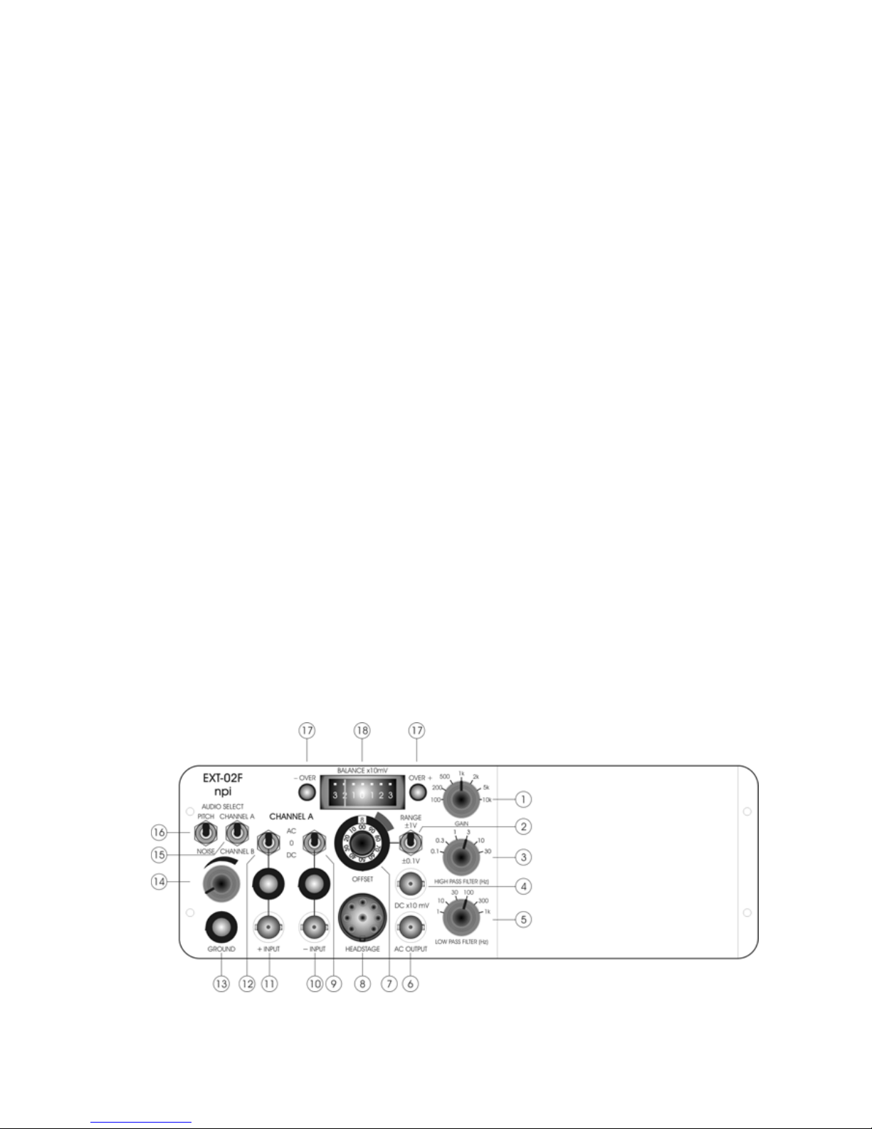
Figure 1: EXT-02F front panel view (one channel version)
___________________________________________________________________________
version 1.0 page 4
Page 5

EXT-02F User Manual
________________________________________________________________________________________________________________
In the following description of the front panel elements, each element has a number that is
related to that in Figure 1. The number is followed by the name (in uppercase letters) written
on the front panel and the type of the element (in lowercase letters). Then, a short description
of the element is given. Since the front panel elements are identical for each channel A and B
(with identical functions and labels) these elements are numbered and described only once
(for channel A).
(1) GAIN switch
7-position switch for selecting the GAIN of the filtered output signal at the AC
OUTPUT connector (# 6).
Amplification factors: x100, x 200, x500, x1k, x2k, x5k, x10k
(2) OFFSET range switch
Switch to set the range for the OFFSET potentiometer (#7).
±1V corresponds to a range from 0 mV to 100 mV at the electrode
±0.1V corresponds to a range from 0 mV to 10 mV at the electrode
(3) HIGH PASS FILTER (Hz) switch
6-position switch for selecting the corner frequency of the HIGH PASS FILTER.
Corner frequencies (Hz): 0.1, 0.3, 1, 3, 10, 30
(4) DC x10 mV output connector
BNC connector providing the unfiltered output signal in DC mode with an
amplification of ten.
(5) LOW PASS FILTER (Hz) switch
6-position switch for selecting the corner frequency of the LOW PASS FILTER.
Corner frequencies (Hz): 1, 10, 30, 100, 300, 1k
Note: A combination of both LOW and HIGH PASS FILTER leads to a filter with bandpass
characteristics.
(6) AC OUTPUT connector
BNC connector providing the filtered output signal in AC mode with an amplification
set by #1.
___________________________________________________________________________
version 1.0 page 5
Page 6
EXT-02F User Manual
________________________________________________________________________________________________________________
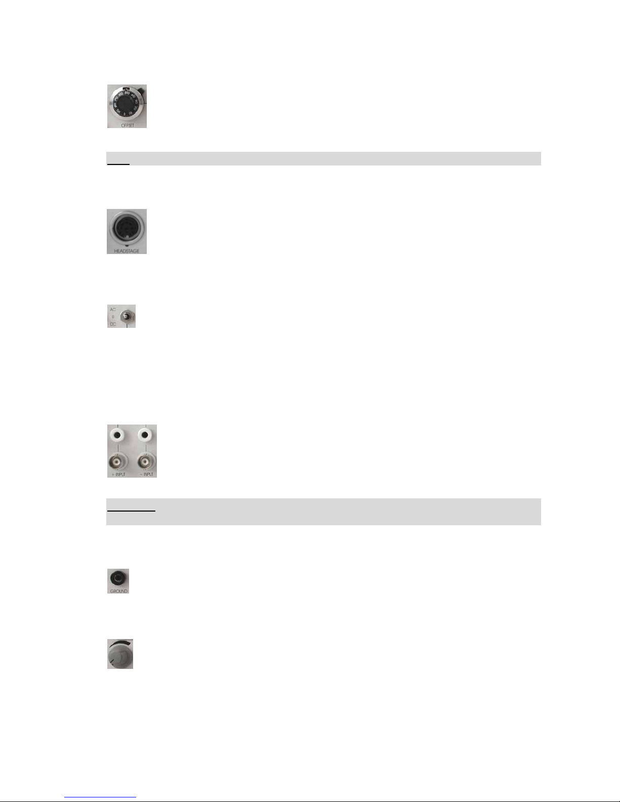
(7) OFFSET potentiometer
10 turn potentiometer for OFFSET compensation for the measured potential in DC
mode, i.e. the potential provided at connector #4. The range is set by switch #2.
The analog BALANCE monitor (#18) displays the offset in the range of ±30 mV
and is used for optimal cancellation of the offset.
Note: Position 5 corresponds to 0 V OFFSET.
(8) HEADSTAGE connector
Connector for the optional headstage.
(9, 12 ) INPUT coupling switches
Switches for selecting the input coupling of the signal.
AC: the input signal is AC coupled with a corner frequency of 0.1 Hz
DC: the input signal is DC coupled
0: the input signal is grounded.
(10, 11) – INPUT, + INPUT connectors
Banana jacks or BNC connectors, respectively for connecting the input signal.
The inputs can be used in single ended or differential configuration. In
differential configuration the signal which is connected to –INPUT is subtracted
from the signal that is connected to +INPUT. If only one input is used (single
ended configuration) the other should be grounded to avoid coupling of noise.
Important: Only one of the INPUTS must be used, i.e. either the banana jacks or the BNC
connectors or the (optional) headstage!!
(13) GROUND connector
Banana jack providing system ground.
(14) Audio volume potentiometer
Potentiometer for setting the volume of the speaker. Turning clockwise will turn up
the sound.
___________________________________________________________________________
version 1.0 page 6
Page 7
EXT-02F User Manual
________________________________________________________________________________________________________________
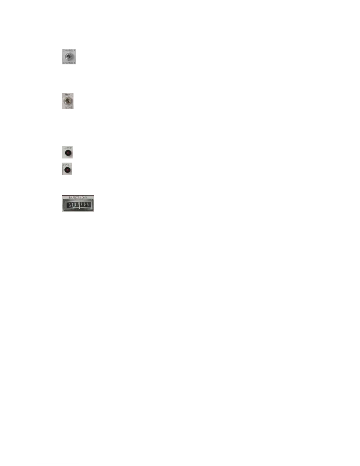
(15) CHANNEL selector
Switch for selecting whether the signal of CHANNEL A or CHANNEL B is monitored
by the audio monitor.
(16) PITCH / NOISE selector
Switch for selecting the audio MODE.
NOISE: The voltage of the INPUT signal is transduced to sound.
PITCH: The voltage of the INPUT signal is converted into a tone with a frequency
equivalent to the amplitude of the INPUT voltage.
(17) + / - OVERLOAD LEDs
LEDs that indicate if the amplifier 10% below it’s positive or negative limit (±10 V).
The linear range of the amplifier is ±12 V.
(18) BALANCE x10mV meter
The analog BALANCE monitor displays the OFFSET in the range of ±30 mV
and is used for optimal cancellation of the OFFSET.
2.4. Description of the Rear Panel
ON / OFF
Control for switching the EXT-02F ON or OFF.
LINE OUT
Phone jack connector for external audio amplification, e.g. with sound cards, power
amplifiers etc.
EXT SPEAKER
Phone jack connector for external speaker.
AC INPUT SUPPLY
Connector for an external power supply (+14 V AC, 0.5 A).
___________________________________________________________________________
version 1.0 page 7
Page 8

EXT-02F User Manual
________________________________________________________________________________________________________________
___________________________________________________________________________
version 1.0 page 8
3. Technical Data
Differential Input: CMR >90 dB at 1 kHz (tested with 0 Ω input resistance)
Input: >10
12
Ω, range ±1 V
Output x10mV DC: gain x10
Output range: ±12 V into 1 kΩ / ±1 V into 250 Ω load
Output AC: selectable gain (x100, x200, x500, x1k, x2k, x5k, x10k)
Output range: ±12 V into 1 kΩ / ±1 V into 250 Ω load
Line Out: impedance: 20 kΩ, 3.5 mm mono phone jack
Speaker Out: impedance: 8 Ω, 3.5 mm mono phone jack
Low pass filter: 1, 10, 30, 100, 300, 1k Hz
High pass filter: 0.1, 0.3, 1, 3, 10, 30 Hz
Offset compensation: ±0.1 V switch position: ±10 mV, 10 turn potentiometer
±1 V switch position: ±100 mV, 10 turn potentiometer
Potential monitor: analog display for the electrode offset, range ±30 mV
Wall power supply: +14V AC, 0.5 A
Dimensions: 245 x 200 x 90 mm
 Loading...