

−
SM5166AV
NIPPON PRECISION CIRCUITS INC.
OVERVIEW
The SM5166AV is a PLL synthesizer IC developed
for application in pagers and fabricated using NPC’s
Molybdenum-gate CMOS process. It incorporates
independently-controlled reference frequency and
operating frequency dividers, and operates from a
low-voltage supply to realize low power dissipation.
It features a charge pump that operates at 3 V,
making possible a wide range of VCO designs.
FEATURES
■
Operating frequency
•f
= 100 MHz (V
FIN
•f
= 90 MHz (V
FIN
■
Reference frequency
•f
= 25 MHz
XIN
(V
= 0.95 V, External Input)
DD1
•f
= 16 MHz*
XIN
(V
= 0.95 V, Internal oscillaton)
DD1
NOTE) * : NPC’s recommended frequency.
Confirm with crystal supplier.
■
Unlock signal output pin
■
Output circuit for passive filter connection
■
10 to 60 ° C operating temperature range
■
Standby function for low current consumption
■
Boost-up signal output for fast locking
■
Supply voltages
•V
= 0.95 to 1.5 V
DD1
(prescaler, counters)
•V
= 2.0 to 3.3 V
DD2
(charge pump)
■
40 to 65528 reference frequency divider ratio
range (with 1/8 prescaler built-in) set by serial
input data
■
1056 to 65535 operating frequency divider ratio
range set by serial input data
■
16-pin VSOP
■
Molybdenum-gate CMOS process
DD1
= 0.95 V)
DD1
= 1.00 V)
PLL Synthesizer IC
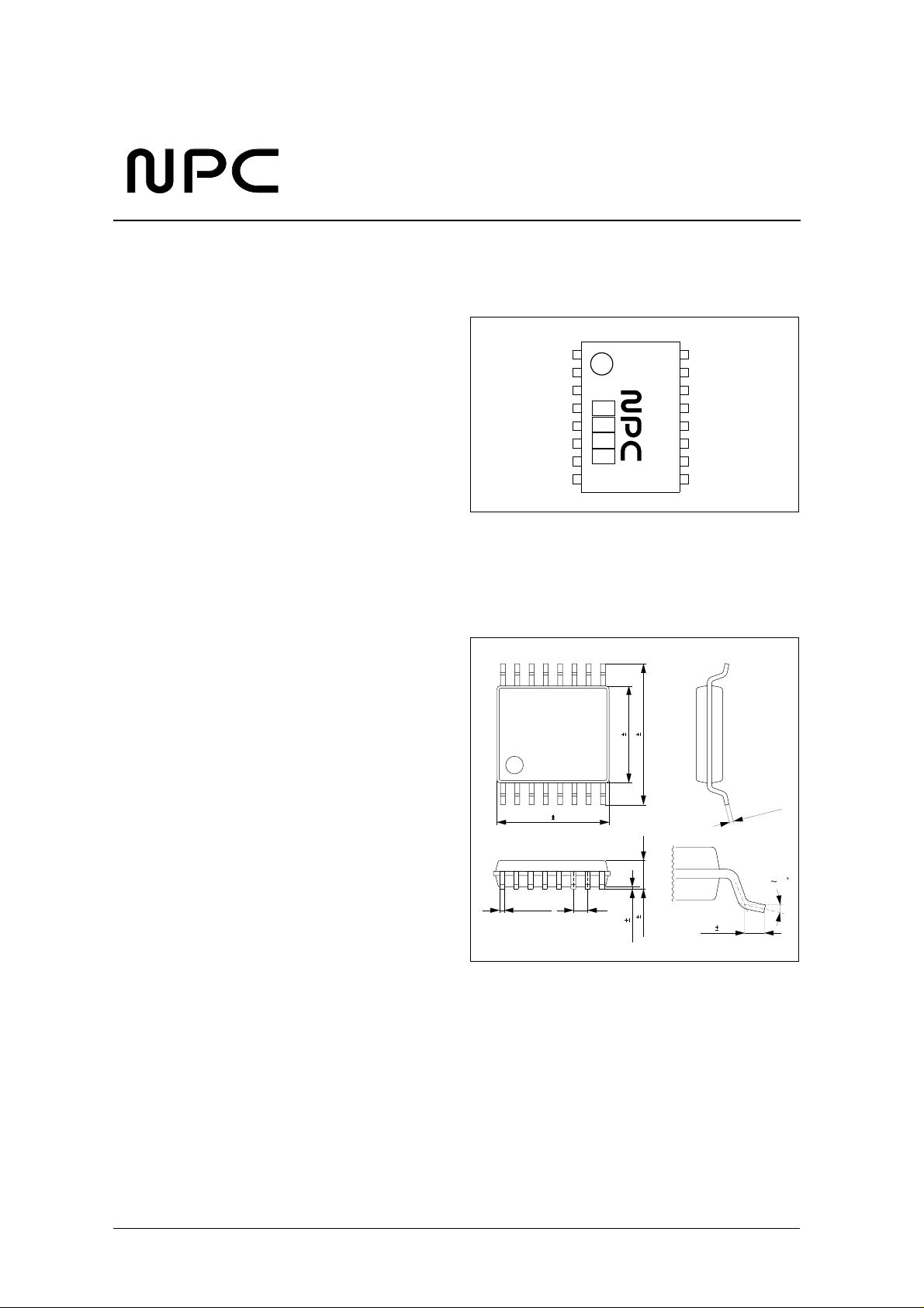
PINOUT
PACKAGE DIMENSIONS
Unit: mm
16-pin VSOP
(TOP VIEW)
XIN
XOUT
VDD2
DB
DO
VSS
FIN
VDD1
5.1 0.2
+ 0.10
0.22
- 0.05
1
16
5166
AV
8
4.4 0.2
6.4 0.2
0.65
1.15 0.1
0.10 0.05
TEST
NC
OPR
LE
DATA
CLK
LD
9
NC
+ 0.10
- 0.05
0.15
010
0.5 0.2
NIPPON PRECISION CIRCUITS—1
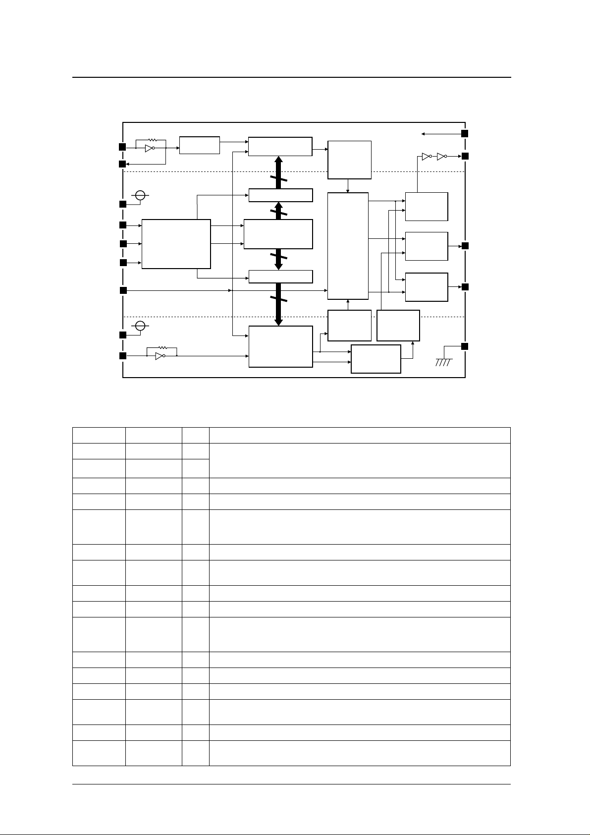
BLOCK DIAGRAM
SM5166AV
XIN
XOUT
VDD2
VDD2
AREA
DATA
CLK
LATCH
SELECTOR
LE
OPR
VDD1
FIN
PIN DESCRIPTION
1/8
PRESCALER
VDD1
AREA
13 BIT
R COUNTER
14 BIT LATCH
16 BIT
SHIFT REGISTER
16 BIT LATCH
16 BIT
N COUNTER
LEVEL
SHIFTER
PHASE
DETECTOR
LEVEL
SHIFTER
GENERATOR
VDD1
AREA
SHIFTER
WINDOW
LEVEL
LOCK
DETECTOR
BOOSTER
S. G.
CHARGE
PUMP
TEST
LD
DB
DO
VSS
Number Name I/O Description
1 XIN I Reference frequency divider crystal (oscillator) connection pins. Alternatively, an external clock input can
2 XOUT O
3 VDD2 – Phase detector, charge pump and boost-up signal 3 V supply
4 DB O boost-up signal output for faster locking
5DOO
6 VSS – Ground pin
7 FIN I
8 VDD1 – Reference frequency and operating frequency prescaler and counter 1 V supply
9 NC – No connection
10 L D O
11 CLK I Control data clock input pin
12 DATA I Control data input pin
13 LE I Control data latch enable signal input pin
14 OPR I
15 NC – No connection
16 TEST I
be connected to XIN. The clock is also output on XOUT.
Feedback resistor b uilt-in f or AC-coupled inputs.
Phase detector output pin.
Built-in charge pump and tristate output means that this output can be connected to a low-pass filter.
The output polarity is preset for connection to a passive filter.
Operating frequency divider input pin.
Feedback resistor b uilt-in f or AC-coupled inputs.
Unlock signal output pin. (Unlocked when HIGH)
The function of LD can be turned OFF using the LD input control bit (LD should be tied LOW when not
used).
Power-save control pin.
Start when HIGH, standby mode when LOW.
Test pin.
Pull-down resistor built-in. Leave open or connect to ground for normal operation.
NIPPON PRECISION CIRCUITS—2
SPECIFICATIONS
Absolute Maximum Ratings
V
= 0 V
SS
Parameter Symbol Pin name Rating Unit
Supply voltage
Input voltage range
Storage temperature range T
Power dissipation P
Soldering temperature T
Soldering time t
−
−
−
−
−
°
°
−
° C
SM5166AV
V
DD1
V
DD2
V
IN1
V
IN2
stg
D
sld
sld
VDD1
VDD2
FIN, XIN, TEST V
OPR, CLK, DATA, LE V
0.3 to 2.0 V
0.3 to 7.0 V
SS
SS
0.3 to V
0.3 to V
+ 0.3 V
DD1
+ 0.3 V
DD2
40 to 125
150 mW
255
10 s
C
C
Recommended Operating Conditions
V
= 0 V
SS
Parameter Symbol Condition Rating Unit
V
Supply voltage
Operating temperature range T
DD1
V
DD2
opr
Electrical Characteristics
V
= 0 V, V
SS
VDD1 operating current consumption I
VDD2 standby current I
FIN maximum operating input frequency f
XIN maximum operating input frequency f
FIN minimum operating input frequency f
XIN minimum operating input frequency f
FIN input amplitude V
XIN input amplitude V
OPR, CLK, DATA, LE LOW-level input
voltage
= 0.95 to 1.5 V, V
DD1
= 2.0 to 3.3 V, T
DD2
Parameter Symbol Condition
Note 1. – 0.70 1.10
DD1
DD2
max1
max2
min1
min2
V
Note 2. – 0.75 1.20
Note 3. – 0.01 10.0 µA
300 mVp-p sine
wave
300 mVp-p sine wave (external input) 25 – – MHz
300 mVp-p sine wave – – 40 MHz
300 mVp-p sine wave (external input) – – 9 MHz
V
DD1
AC coupling
FIN
V
DD1
AC coupling
f
= 25 MHz sine wave, AC coupling
XIN
XIN
(external input)
IL
= − 10 to 60 ° C
a
= 0.95 to 1.50 V, f
= 1.00 to 1.50 V, f
= 0.95 to 1.50
V
DD1
V
= 1.00 to 1.50
V
DD1
V
= 90 MHz,
FIN
= 100 MHz,
FIN
0.95 to 1.5 V
2.0 to 3.3 V
10 to 60
Rating
Unit
min typ max
mA
90 – –
MHz
100 – –
0.3 – –
Vp-p
0.3 – –
0.3 – – Vp-p
– – 0.3 V
NIPPON PRECISION CIRCUITS—3
SM5166AV
−
Parameter Symbol Condition
OPR, CLK, DATA, LE HIGH-level input
voltage
FIN LOW-level input current I
XIN LOW-level input current I
FIN HIGH-level input current I
XIN HIGH-level input current I
DO , DB LOW-level output current I
DO, DB HIGH-level output current I
Tristate output high-impedance leakage
current
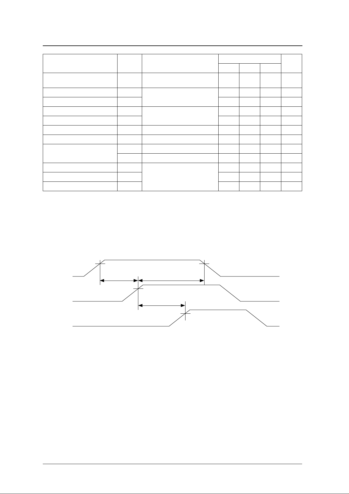
DATA → CLK setup time t
CLK → LE setup time t
Hold time t
1. V
= 0.95 to 1.05 V, V
DD1
load
2. V
= 1.00 to 1.05 V, V
DD1
load
3. V
= 0 V , V
DD1
4. DO and DB outputs are derived from the V
= 2.7 to 3.3 V , OPR = LOW, no input/output load (i.e. CLK = DATA = LE = 0 V)
DD2
= 2.7 to 3.3 V, f
DD2
= 2.7 to 3.3 V, f
DD2
5. DO and DB outputs are derived from the V
V
IH
IL1
V
= 0 V
IL2
IH1
IH2
OL
OH
I
OZL
I
OZH
SU1
SU2
H
= 90 MHz (300 mVp-p sine wave), f
FIN
= 100 MHz (300 mVp-p sine wave), f
FIN
supply. V
DD2
supply. V
DD2
IL
V
= V
IH
DD1
Note 4. 1.0 – – mA
Note 5. 1.0 – – mA
V
= 0 V – – 100 nA
OL
V
= V
OH
DD2
See the timing diagrams.
= 2.7 to 3.3 V , V
DD2
= 2.7 to 3.3 V , V
DD2
OL
OH
Rating
min typ max
1.5 – – V
––60µA
––10µA
––60µA
––10µA
– – 100 nA
2––µs
2––µs
2––µs
= 14.4 MHz (300 mVp-p sine wave), OPR = HIGH, no output
XIN
= 14.4 MHz (300 mVp-p sine wave), OPR = HIGH, no output
XIN
= 0.4 V
= V
0.4V
DD2
Unit
DATA, CLK, and LE timing
VIH
DATA
CLK
LE
tSU1
VIH
tH
VIH
tSU2
VIH
NIPPON PRECISION CIRCUITS—4
 Loading...