

Page 1

M-Series OTDRs
User’s Guide
Page 2

2
Limited Warranty
One Year Limited Warranty
All Noyes products are warranted against defective material and workmanship for a period of one
year from the date of shipment to the original customer.
Any product found to be defective within the warranty period will be repaired or replaced by Noyes.
In no case will Noyes liabilities exceed the original purchase price of the product.
Exclusions
The warranty on your equipment shall not apply to defects resulting from the following:
Unauthorized repair or modification •
Misuse, negligence, or accident
•
CE Information
These instruments have been designed and tested to comply with the relevant
sections of any applicable specifications including full compliance with all essential
requirements of all applicable EU Directives.
Returning Equipment
To return equipment, please contact Noyes to obtain additional information and a Service Request
(S.R.) number. To allow us to serve you more efficiently, please include a brief description specifying
the reasons for the return of the equipment.
AFL Telecommunications
Noyes Test & Inspection
16 Eastgate Park Road
Belmont, NH 03220
Tel: 800-321-5298
603-528-7780
Fax: 603-528-2025
This is a user’s guide for the M-series OTDR. It assumes
basic knowledge in the use of an OTDR, OPM, and a PC.
Page 3

3
Table of Contents
Safety Information ...........................................4
Getting Started: Front Panel Keys ...............................5
Main Menu: Selecting the Mode
................................6
M700 Menus Tip: “...” Function .................................6
Getting Started: Display Features................................7
Setup: General Settings.......................................10
Setup: Full Auto Mode Settings .................................11
Setup: Expert Mode Settings ...................................12
Setup: Real-Time Mode Settings ................................13
Setup: Event Settings ........................................14
Event Settings: Pass/Fail......................................15
Setup: OPM Mode Settings ....................................16
Setup: New Job Creation......................................19
Setup: Results Manager ......................................20
Job Creation in Results Manager ................................21
Job Selection from a Test Mode.................................22
Opening a Trace File for Review .................................23
Saving Test Results..........................................23
Running Tests & Viewing Results . . . . . . . . . . . . . . . . . . . . . . . . . . . . . . . .24
Trace Page Features .........................................25
Event Table & Summary Results.................................27
Fault Locating: Full Auto ......................................28
Two Point A/B Measurement ...................................28
Text Editor ................................................29
Numerical Editor ............................................29
Transferring Files ...........................................30
Recommended Accessories....................................31
Specifications ..............................................32
Cleaning Tips ..............................................38
FAQs ....................................................40
Tips: Expert OTDR Setup......................................40
Recharging Batteries .........................................41
Repair and Calibration ........................................41
View Version Information ......................................41
Contact us ................................................41
© 2009-2010, AFL Telecommunications, all rights reserved. M000-00-1000 Revision 1C, 2010-01-22
Specifications are subject to change without notice.
Page 4
4
Safety Information
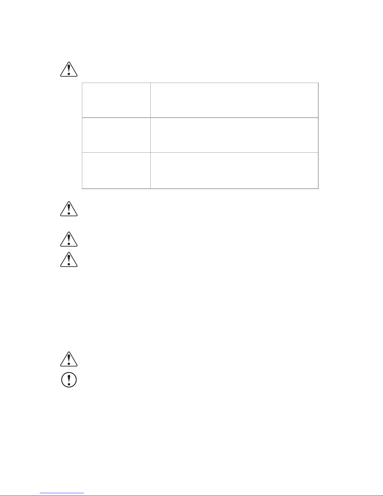
WARNING! Use of procedures or adjustments other than those specified herein may result
in hazardous radiation exposure.
850/1300 nm
multimode OTDR port
This is a CLASS I LASER output
1310/1550 nm
single-mode OTDR port
This is a CLASS I LASER output
VFL port
This is a CLASS II LASER output. Do not stare into beam
CAUTION! To avoid serious eye injury, never look directly into the optical outputs of fiber
optic network equipment, test equipment, patch cords, or test jumpers. Refer to your
company’s safety procedures when working with optical systems.
WARNING! Use only the specified AC adapter. Use of another type of AC adapter can
damage the instrument and create the danger of fire and electrical shock.
WARNING! To avoid the danger of fire and electrical shock:
Never use a voltage that is different from that for which the AC adapter is rated. •
Do not plug the unit into a power outlet that is shared by other devices. •
Never modify the power cord or excessively bend, twist, or pull it. •
Do not allow the power cord to become damaged. Do not place heavy objects on the •
power cord or expose it to heat.
Never touch the AC adapter while your hands are wet. •
Should the power cord become seriously damaged (internal wiring exposed or shorted), •
contact the manufacturer to request servicing.
CAUTION! Do not run any tests or perform functions that activate an OTDR laser unless
fiber is attached to the corresponding OTDR port.
NOTICE! Noyes OTDR contains no user serviceable parts. Except for changing batteries
and cleaning optical ports, this instrument must be returned to Noyes or authorized agents
for repair and calibration.
IMPORTANT! Proper care in handling should be taken when using any precision optical
test equipment. Scratched or contaminated optical connectors can impact the performance
of the instrument. It is important to keep the dust caps in place when the unit is not being
used.
Page 5
5
Getting Started: Front Panel Keys
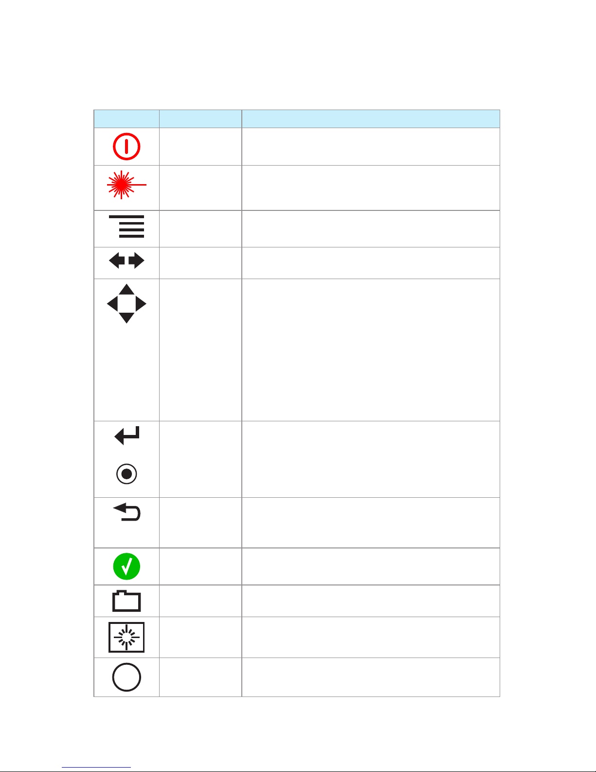
The use of each key is summarized in the table below.
KEY SYMBOL KEY NAME KEY FUNCTION
Power
Press and hold (approx. 1 sec.) to turn an OTDR on or off
VFL laser
ON 2Hz - Press and hold (approx. 2 sec.) LED will flash
ON CW - Press and hold (approx. 4 sec.) LED will be solid
OFF - Press and hold (approx. 1 sec.) LED should be OFF
Menu
Press to access the Main Menu
Left and Right
Tab keys
Press to display the next/previous available Home and
Settings pages or View tab
Arrow keys
The arrow keys provide several functions as follows:
• In the Home and Settings pa
ges, Main Menu and
Results pages, these keys are used to navigate menus
and change setup parameters
• In the Trace page, these keys are used to move the
cursors
• In the Zoom Adjust page, these keys adjust vertical and
horizontal zoom levels
• In the LSA Adjust page these keys move cursors and
adjust zoom levels
or
Enter
This key provides several functions as follows:
• In the Main Menu: press this key to open a Test mode,
Results Manager, or Settings
• In the Trace page, press this key to toggle between [A]
and [B] cursor
Back
Press one or more times, depending on which menu or editor
submenu is displayed, to return to the current mode Home
page
Test
Press to start or stop a test
Save
Press to save the currently displayed test results
Backlight
Press to set level of brightness
Soft keys
The label shown on the display above each key indicates the
current use of each function key
Page 6
6
Main Menu: Selecting the Mode
M700 Menus Tip: “...” Function
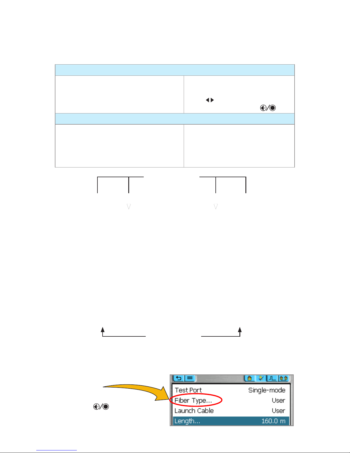
Two types of modes are available from the Main Menu as follows:
TEST MODES: OTDR and OPM
Used to perform OTDR and OPM tests
To select the desired mode
Tap the appropriate touch screen icon
•
Use • arrows to indicate the desired
mode icon, and then press key
UTILITY MODES: Results, Settings, and New Job
Used to select user preferences, perform general
settings, create a new job (set up a file structure
and define the fiber under test location), manage
saved test results, and perform other non-test
functions
To select the desired mode
Tap the appropriate touch screen icon
•
Press the appropriate soft key located •
below each touch screen icon
When a menu option is followed
by three dots “…”,
it means that there is a submenu
available. Press
key to
display a submenu and see
additional information.
Test modes icons
Utility modes icons
Page 7
7
Getting Started: Display Features
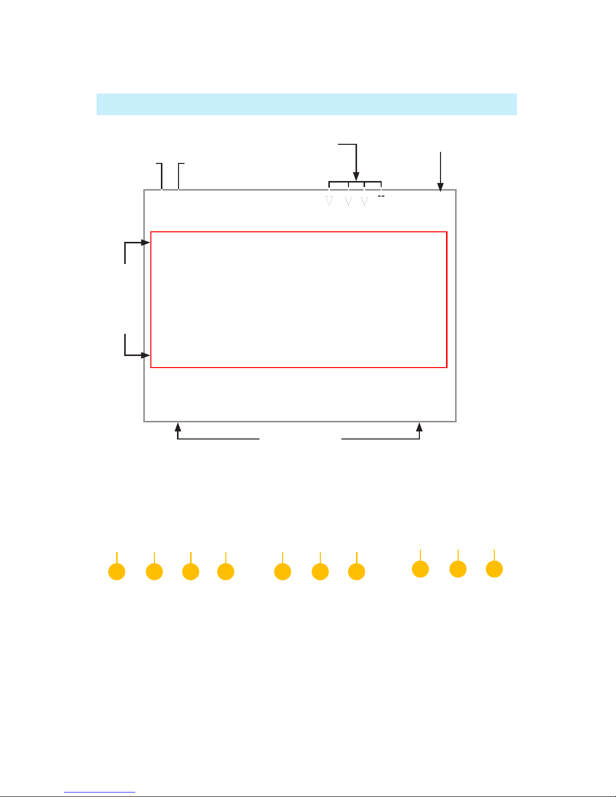
Settings Page Tabs
Test Settings View
Press tabs to perform the following:
Home mode1 - display OTDR setup, change Fiber and Cable ID parameters
Test Settings2 - define OTDR test setup
Event Settings3 - define Events settings and Pass/Fail Settings
Job Settings4 -define Job, End Locations, Cable ID, and Operator parameters
Data Table (OPM test mode only!) 5 - review OPM test results
Battery icon (see legend, page 8)
Full Auto/Expert OTDR mode
Soft key labels
Main Menu tab
Settings page tabs
Back tab
Menu area
1 2 3 4
Real-Time OTDR mode
1 2 4
OPM mode
1 5 4
Page 8
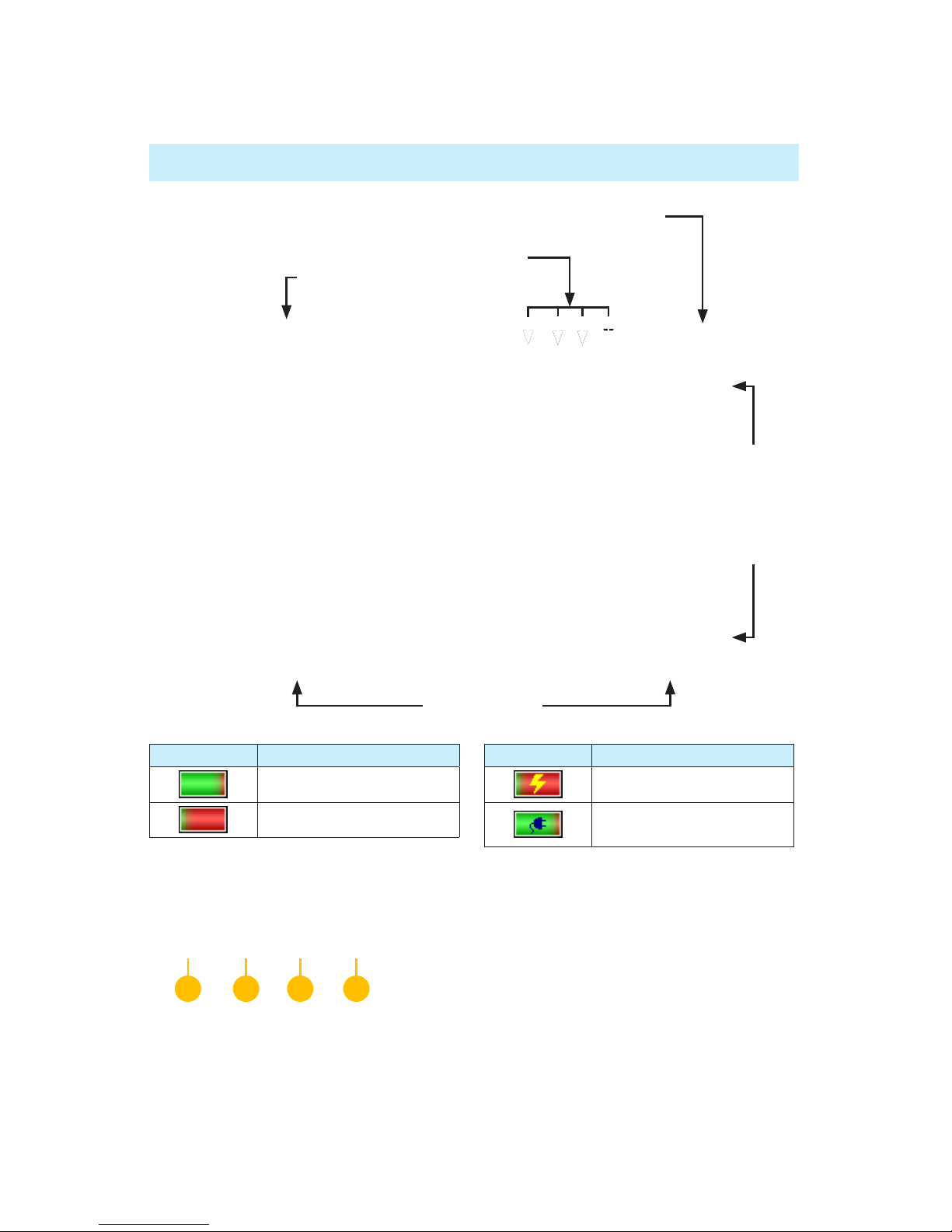
8
Trace Page Tabs
OTDR Trace View
Press tabs to display test data as follows:
Trace page1 - OTDR trace, test setup, A/B cursor data, Loss Method, Loss, Reflectance
Event Table2 - OTDR trace; event Location, Type, Reflectance, Loss, event Pass/Fail (if turned On)
Summary Table3 - OTDR trace, Link Length, ORL, Loss, link Pass/Fail (if turned On)
Job Information 4 - setup parameters of the currently displayed trace
BATTERY ICON BATTERY STATUS
Green - fully charged
Red - discharged
BATTERY ICON BATTERY STATUS
Charging - AC connected
Fully Charged - AC
connected
Getting Started: Display Features
1 2 3 4
Battery icon (see legend below)
Results area
Soft key labels
Page header
Trace page tabs
Page 9
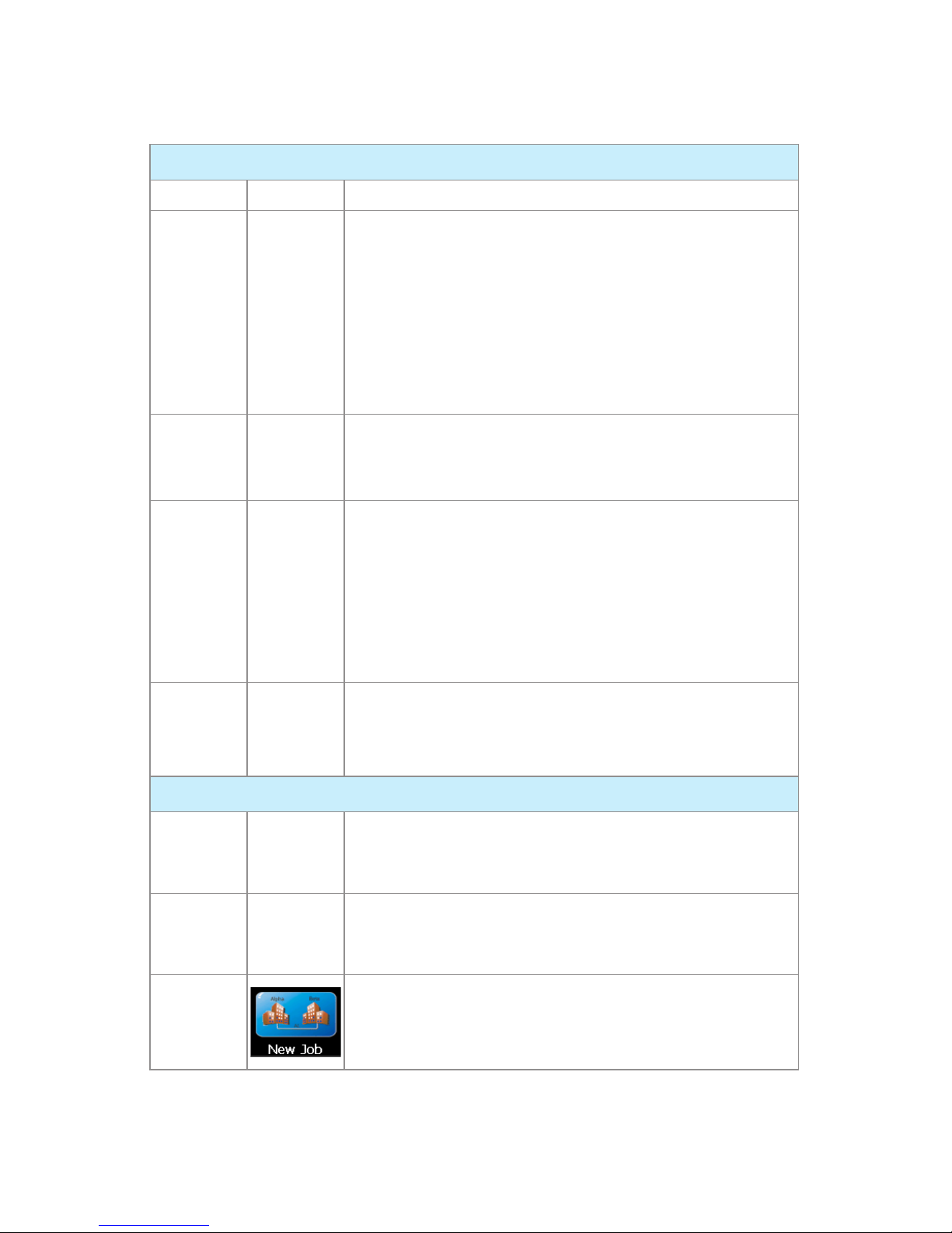
9
TEST MODES: OTDR and OPM
Test Mode Icon Description
Full Auto
OTDR
This is the recommended mode for users who are not familiar with
OTDR operation. In the Full Auto mode, OTDR parameters such
as Range, Pulse Width, and Averaging Time are set automatically.
Tests are done at two wavelengths and always include an Event
Table and Summary page. Pass/Fail Thresholds are set to default
with an option to be turned off.
Note: in the Expert mode, the Events Menu contains Event
Threshold and Pass/Fail Threshold Settings allowing the user to
change these settings and turn them on or off.
Real-Time
OTDR
This is the best mode for real-time troubleshooting. Note that the
Wavelength setting can only be set to individual wavelengths. The
Range, Pulse Width, and Filter parameters are set by the user.
Expert
OTDR
This mode is available for experienced users. It provides the most
setup flexibility. Users can set Range, Pulse Width, and Averaging
Time manually (Setup = Manual) or automatically (Setup = Auto
Once or Setup = Auto). Users can either enable the event table
(Events = Auto) or disable the event table (Events = Off).
Note: in the Expert mode, the Events Menu contains Event
Threshold and Pass/Fail Threshold Settings allowing the user to
change these settings and turn them on or off.
OPM
This mode is available to perform Optical Power Meter
measurements.
UTILITY MODES: Results, Settings, and New Job
Results
This mode provides the file manager functions to handle the results
of OTDR, OPM tests and to set up Jobs.
Settings
This mode allows the user to adjust General Settings (Language,
Distance Units, Sounds, Auto Off function, Date/Time, Company
Name) and displays the OTDR version information.
New Job
This mode is available for creating new jobs (setting up a file
structure and defining the fiber under test location: Drives, Folders,
Jobs, Routes [End Locations], Cables, Test Equipment Location,
and Operators).
Main Menu: Selecting the Mode
Page 10
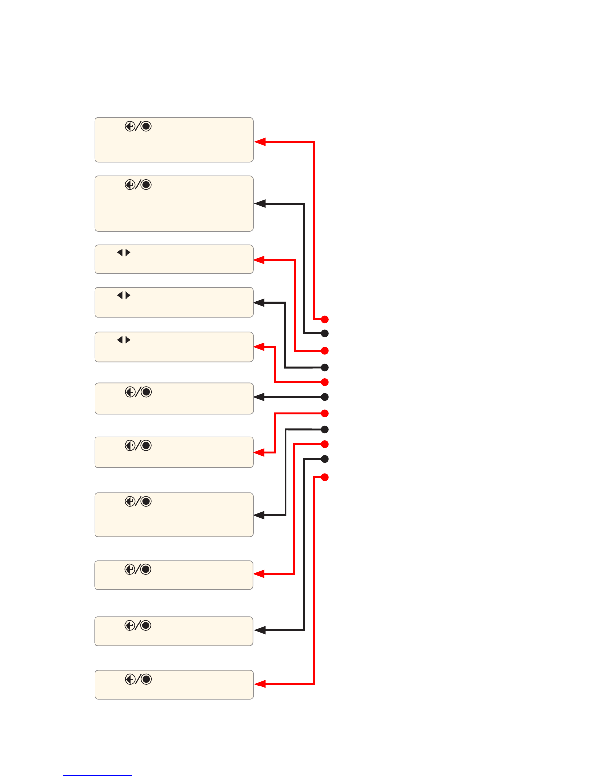
10
Setup: General Settings
The General Settings may be completed as indicated below.
Press key to display
submenu, which allows setting Time
Press key to display
submenu, which allows defining
Company Name
Press key to display Touch
Panel calibration screen
Press key to display the
System Information screen
Press key to reset all
Settings to the default values
Press key to display
submenu, which allows setting Date
Press key to display
submenu, which allows the selection
of available languages
Press key to display
submenu, which allows the selection
of available date/time/numbers
formatting options
Use arrows to select units of
measure
Use arrows to toggle the Beeper
function On/Off
Use arrows to define the Auto
Off (set number of minutes) function
Page 11
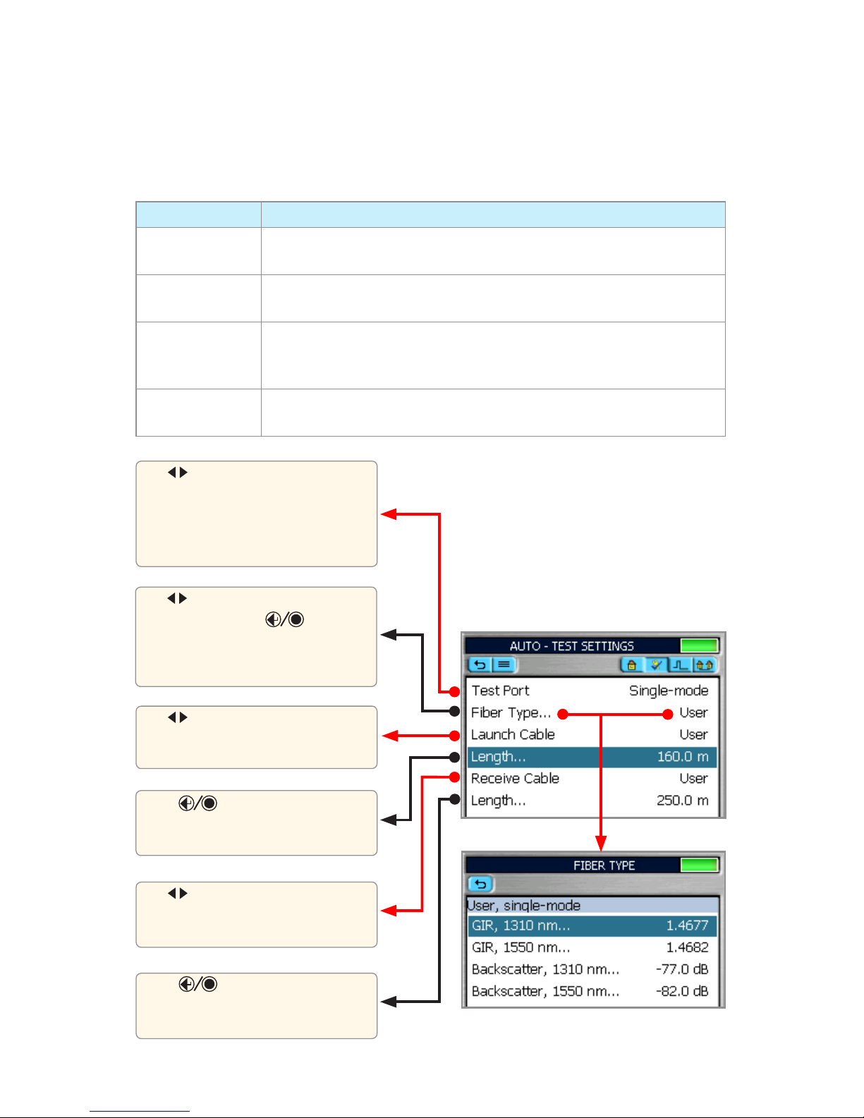
11
Setup: Full Auto Mode Settings
Core Settings
Full Auto mode settings are common for all OTDR Test modes and will be referred to as Core
Settings.
PARAMETER DEFINITION
Test Port
This parameter indicates that a multimode or single-mode laser is used to
generate an OTDR trace
Fiber Type
This parameter is used to set fiber type which determines the GIR and
Backscatter Coefficient
Launch Cable
(Launch Cord)
see page 31
A test cable used to connect the OTDR to the near end of the link under
test that is long enough to allow the OTDR to measure the loss of the first
connection under the test
Receive Cable
(Tail Cord)
A test cable used to terminate the far end of the link under test that is long
enough for the OTDR to measure the loss of the last connection
Press key to display editor
submenu, which allows setting the
length of the Receive Cable used.
Press key to display editor
submenu, which allows setting the
length of the Launch Cable used.
Use arrows to select Fiber Type.
If set to [User], press
key
to display submenu, which allows
defining the GIR and Backscatter
parameters.
Use arrows to select the Launch
Cable option.
If set to [User], set [Length] parameter.
Use arrows to select the Receive
Cable option.
If set to [User], set [Length] parameter.
Use arrows to select single-mode
or multimode Test Port (QUAD models).
For the single-mode M700 OTDR,
single-mode Test Port is the default
setting.
Page 12
12
Setup: Expert Mode Settings
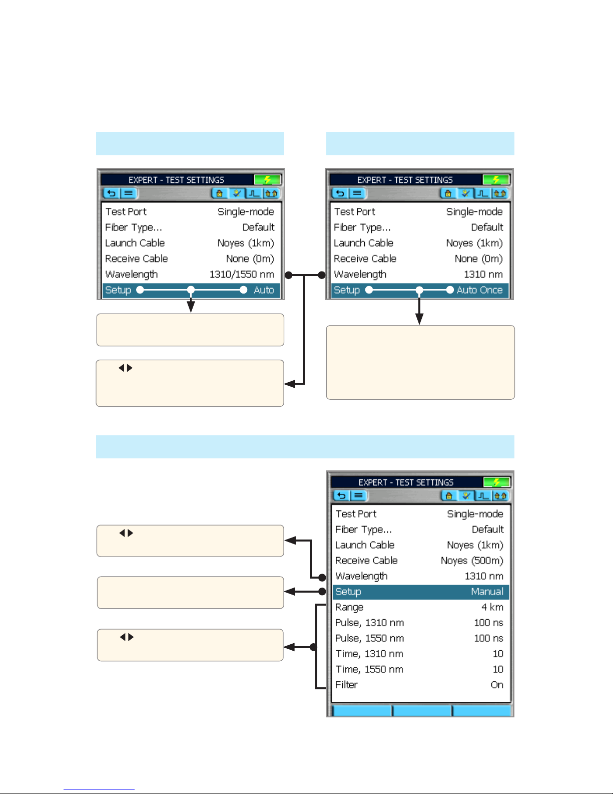
In addition to Core Settings (see Full Auto mode settings), the Expert test mode allows you to set the
Wavelength, Range, Pulse Width, Averaging Time, and Filter parameters.
Setup - Auto
Setup - Manual
Setup - Auto Once
If set to [Auto], OTDR sets Range, Pulse
Width, Time, and Filter for each test.
If set to [Auto Once], OTDR sets Range,
Pulse Width, Time, and Filter for the first
test. After test, returns user to OTDR
Home page in Manual mode, where user
may change any setting for next tests.
If set to [Manual], you will need to set
Range, Pulse, Time, and Filter
Use arrows to display the desired
value or option
Use arrows to select a single
wavelength or dual wavelengths
Use arrows to select a single
wavelength or dual wavelengths for next
tests.
Page 13
13
Setup - Manual (continued)
Note: The Range, Pulse Width, and Averaging Time parameters are user-selectable if the [Setup]
parameter is set to [Manual].
PARAMETER DESCRIPTION
Range
The Range parameter determines the distance range of the full (unzoomed) trace.
It also determines Resolution - the distance between data points in the trace: the
longer the range, the wider the data point spacing. We recommend selecting the
shortest distance range that is longer than the fiber under test. For example, to test
a fiber that is 1.5 km long (including launch and receive cables), select the 2 km
range. Available Range values:
Wavelength (nm) Distance Range Resolution (set by OTDR)
MM 850, MM 1300
SM 1310, SM 1550,
SM 1625
2 km (6561ft) 0.125 m (0.41 ft)
< 4 km (13123 ft) 0.25 m (0.82 ft)
8 km (26246 ft) 0.5 m (1.64 ft)
16 km (52493 ft) 1 m (3.28 ft)
32 km (104986 ft) range/16 km (range/5249 ft)
Pulse
Width
The M-series OTDR can operate using different pulse widths. Short pulse widths
provide the shortest event and attenuation dead zones. Long pulse widths provide
the best event detection on long fibers.
Averaging
Time
The [Time] parameter determines the duration of a timed test. Available time
settings: 5 • 10 • 30 • 60 • 90 • 180 sec
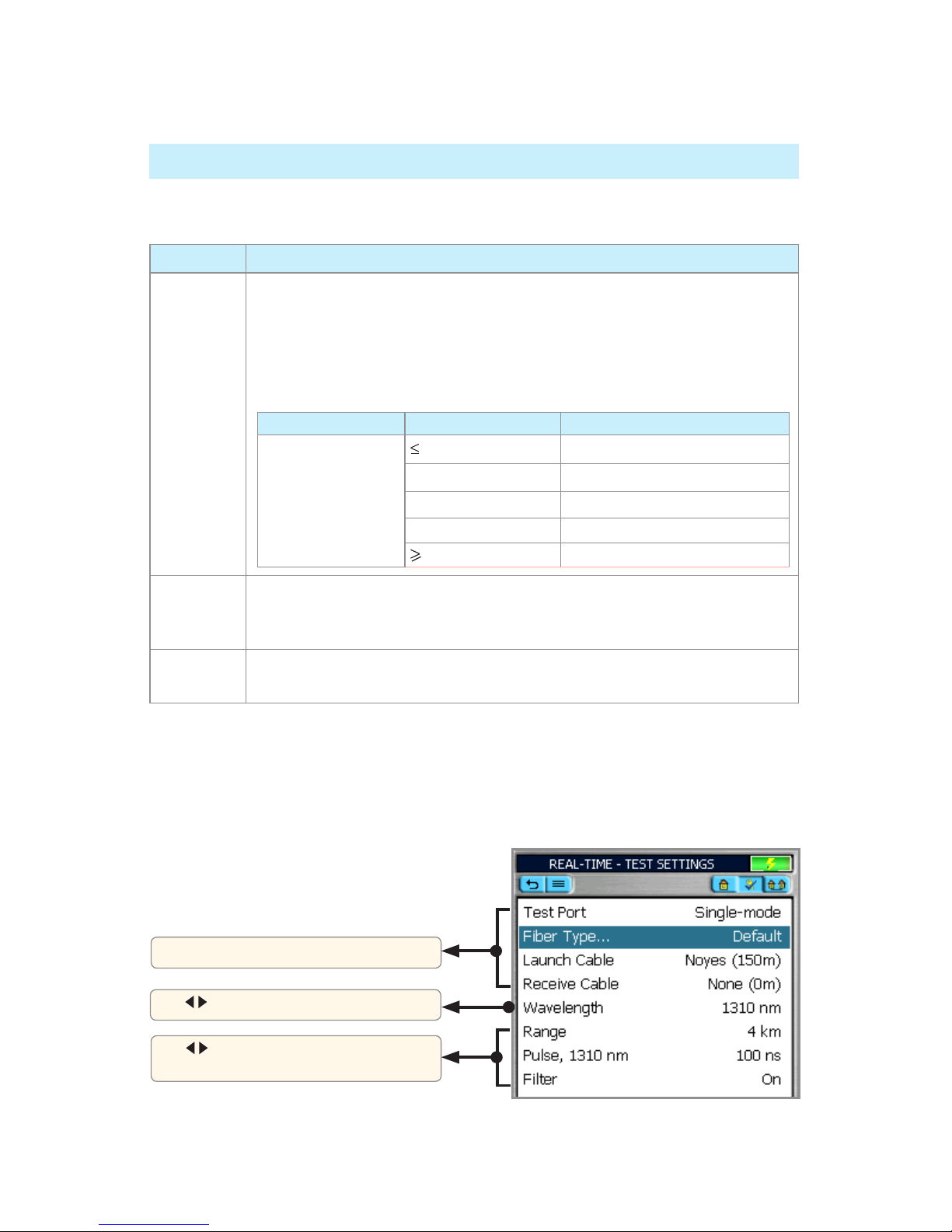
Setup: Real-Time Mode Settings
In addition to Core Settings, the Real Time mode allows you to set the Wavelength, Range, Pulse
Width, and Filter parameters.
Setup: Expert Mode Settings
See Full Auto mode Settings (page 11)
Use arrows to display the desired
value or option
Use arrows to select a wavelength
Page 14
14
Setup: Event Settings
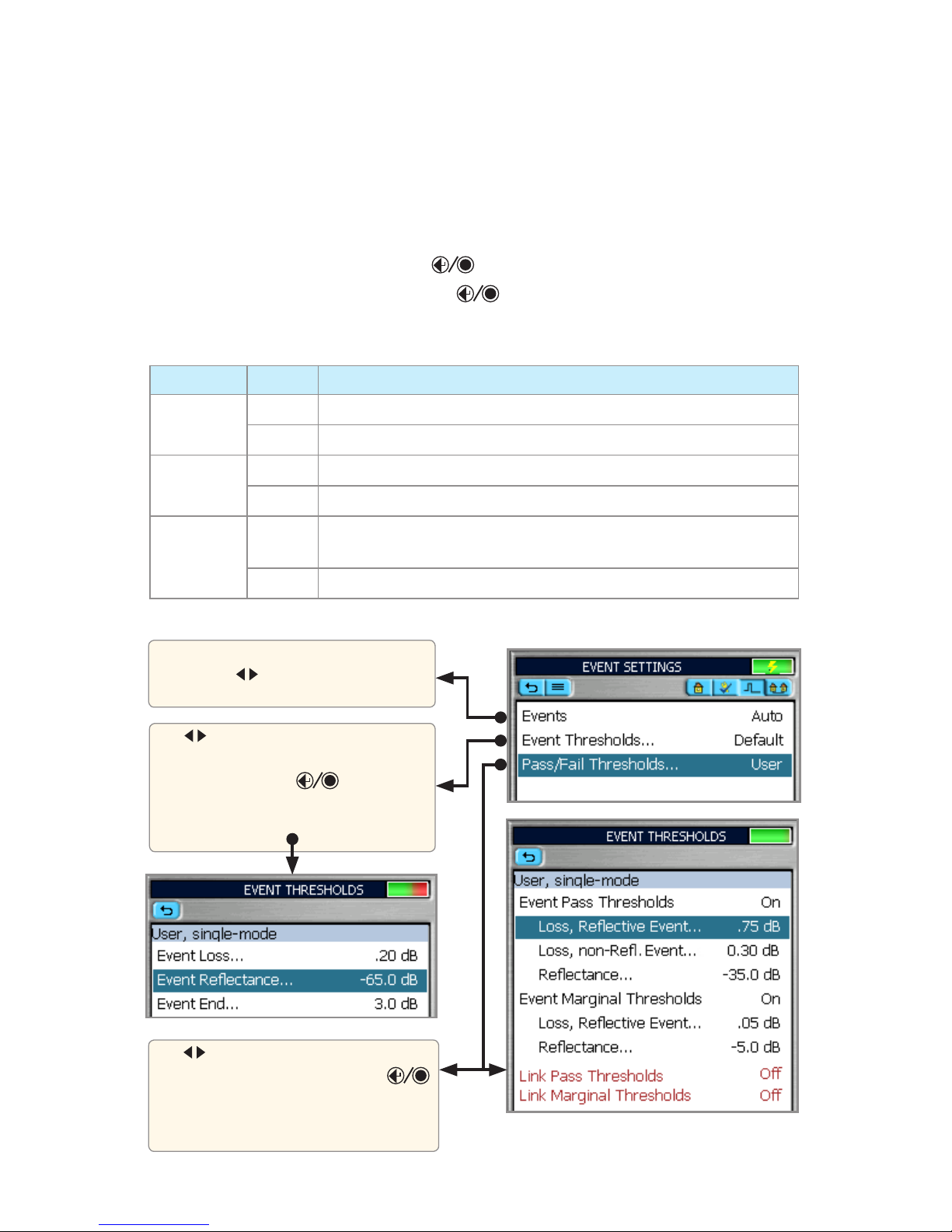
The Event Settings Menu features three parameters: Events, Event Thresholds, and Pass/Fail
Thresholds.
In Full Auto OTDR test mode these parameters are set as follows:
Events - set to Auto and an Event Table is calculated for every test. •
Event Thresholds - set to Default. Press • key to view the default values (see table, pg. 15).
Pass/Fail Thresholds - set to Default. Press • key to view the default values (see table, page
15) and turn Event Pass Thresholds On/Off (Threshold set to default values).
In Expert OTDR test mode, these parameters may be set as indicated below:
PARAMETER OPTION DESCRIPTION
Events
Auto An Event Table is calculated for every test
Off Event Table is not calculated
Event
Thresholds
Default Set to default values (see table, page 15)
User Values may be adjusted within allowed limits (see table, page 15)
Pass/Fail
Thresholds
Default View default values (see table, page 15) and turn Event Pass Thresholds
On/Off (Threshold set to default values)
User Values may be adjusted within allowed limits (see table, page 15)
In Expert mode: [Auto] is the default
setting. Use arrows to toggle between
the [Auto] or [Off] options.
Use arrows to select the [Default] or
[User] option.
If set to [User], press key to
display editor submenu, which allows
defining the Threshold parameters.
Use arrows to select the [Default] or
[User] option. If set to [User], press
key to display a submenu, which allows
defining Event and Link Pass/Fail and
Marginal Threshold values.
Page 15
15
Event Settings: Pass/Fail
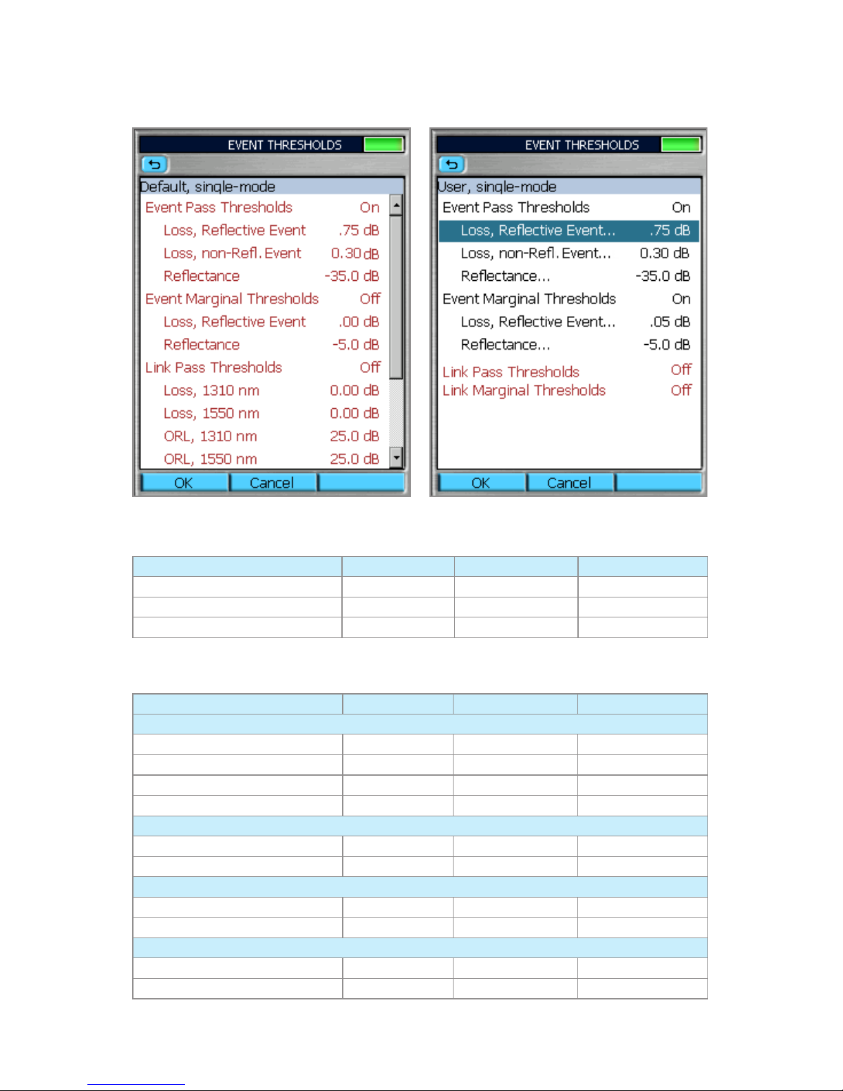
Event Thresholds Chart
Threshold Min Value (dB) Default Value (dB) Max Value (dB)
Event Loss 0.05 0.10 1.0
Event Reflectance -65.0 -65.0 -35.0
Event End 1.0 3.0 25.0
Event Pass Thresholds
Threshold Min Value (dB) Default Value (dB) Max Value (dB)
Event Pass Thresholds
Loss, Reflective Event 0.05 0.75 3.00
Loss, Non-reflective Event 0.05 0.30 3.00
Reflectance: 1310, 1550 nm -65.0 -35.0 -20.0
Reflectance: 850, 1300 nm -45.0 -22.0 -15.0
Event Marginal Thresholds
Loss, Reflective Event 0.00 0.00 1.00
Reflectance 0.00 -5.00 -10.0
Link Pass Thresholds
Loss: 850, 1300, 1310, 1550 nm 0.00 0.00 35.0
ORL: 850, 1300, 1310, 1550 nm 20.0 25.0 65.0
Link Marginal Thresholds
Loss: 850, 1300, 1310, 1550 nm 0.00 0.00 5.00
ORL: 850, 1300, 1310, 1550 nm 0.00 0.00 10.0
Page 16
16
Setup: OPM Mode Settings
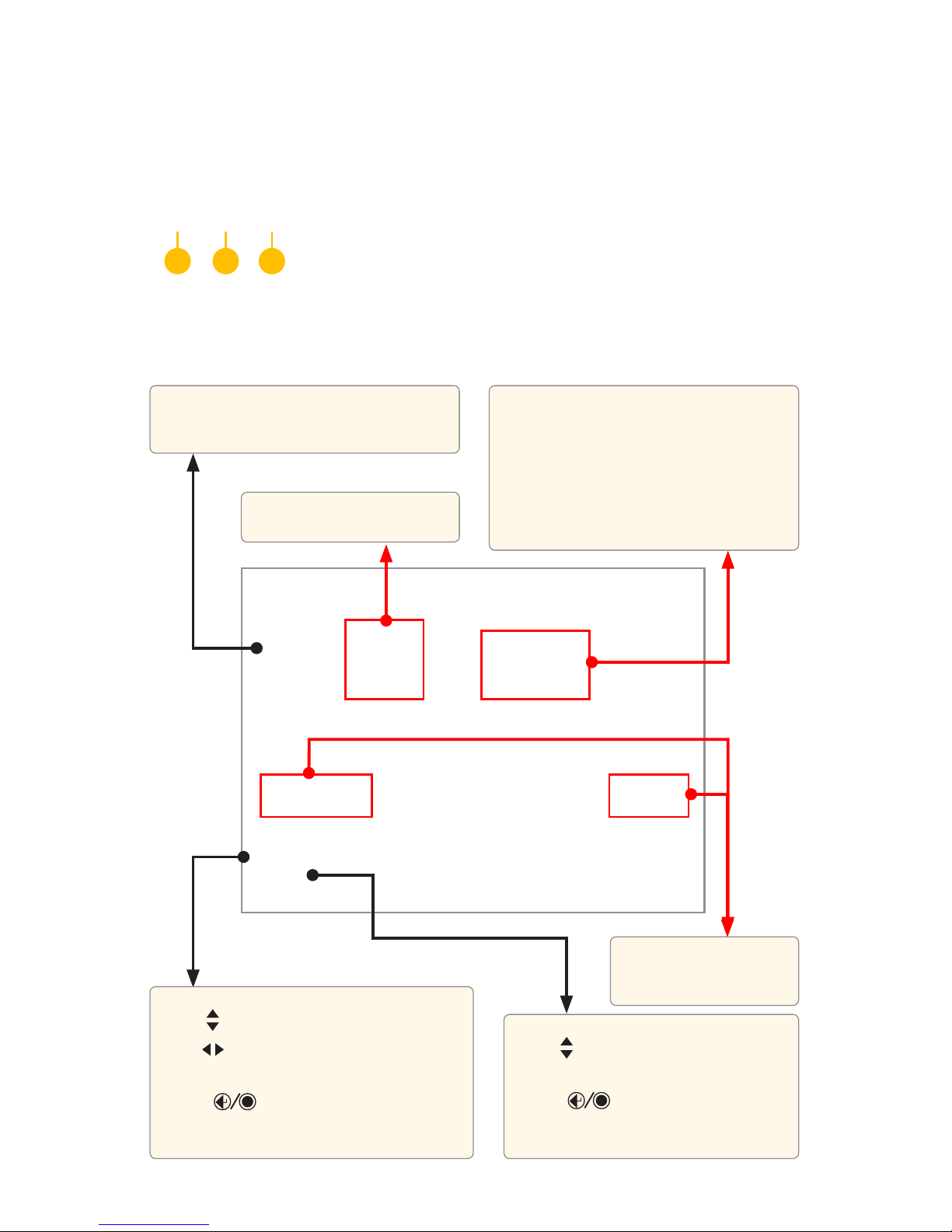
This field displays test readings:
Measured Insertion Loss values in dB or •
measured Power in dBm or mW
If the power or loss is too high/low for the •
OPM to measure, [High]/[Low] label is
displayed in place of the Loss or Power
values
OPM Page Tabs
Home Page Indicators
Press tabs to perform the following:
Home mode1 - display the OPM setup, current test values, and
Reference values. From the Home mode page you may change Fiber
and Cable ID parameters.
Data Table2 - review OPM test results.
Job Settings3 - defin e Job, Locations, Cable I D, a nd Operator par ameters.
1 2 3
Displays the currently selected
or detected wavelength(s)
Location and Operator ID
are user set in the Job
Setting Menu
This field displays the current OPM test mode
Wave ID: receiving wavelength ID’d light
Tone in Hz: receiving tone signal in HZ
Fiber Number - user set
Use • arrows to select the [Fiber] parameter
Use • arrows to increment/decrement the
Fiber number one number at a time
Press • key to open a numerical editor,
which allows entering a fiber number from
001 to 999
Cable ID - user set
Use
• arrows to select the [Cable ID]
parameter
Press
• key to open the Results
Manager, which allows the user to make
changes to the Job Settings
Page 17
17
OPM Operation - Testing Multimode/Single-mode Links
Step I - Set the Reference (One Jumper Method)
From the OTDR Main Menu, select the OPM (optical power meter) test mode. Turn on your OLS 1
(optical light source) and allow the light source to stabilize (minimum of 15 minutes).
If not using the [Wave ID] feature, set both instruments to the desired test wavelength.2
Select the appropriate fiber optic transmit and receive test jumpers. The fiber type of these 3
jumpers must match the fiber type of the link to be tested.
Perform one of the following:
For Multimode testing: wrap and secure the transmit jumper five times around the •
appropriate diameter mandrel.
For Single-mode testing: make a loop in a transmit jumper and secure it with a piece of tape. •
TIA testing - 30 mm loop
IS0 testing - 30-50 mm loop
Note: Clean both ends of the transmit jumper.
Connect the transmit jumper to the appropriate (MM or SM) output port of the OLS. 4
Mount an adapter cap on the OPM port that matches the free connector on the transmit jumper. 5
Connect the free end of the transmit jumper to the OPM port.6
If measured output power is outside of the normal range (specified by manufacturer), clean all 7
fiber connections or replace the transmit jumper. Repeat steps 4 - 7.
To set the reference level at the current wavelength, perform the following:8
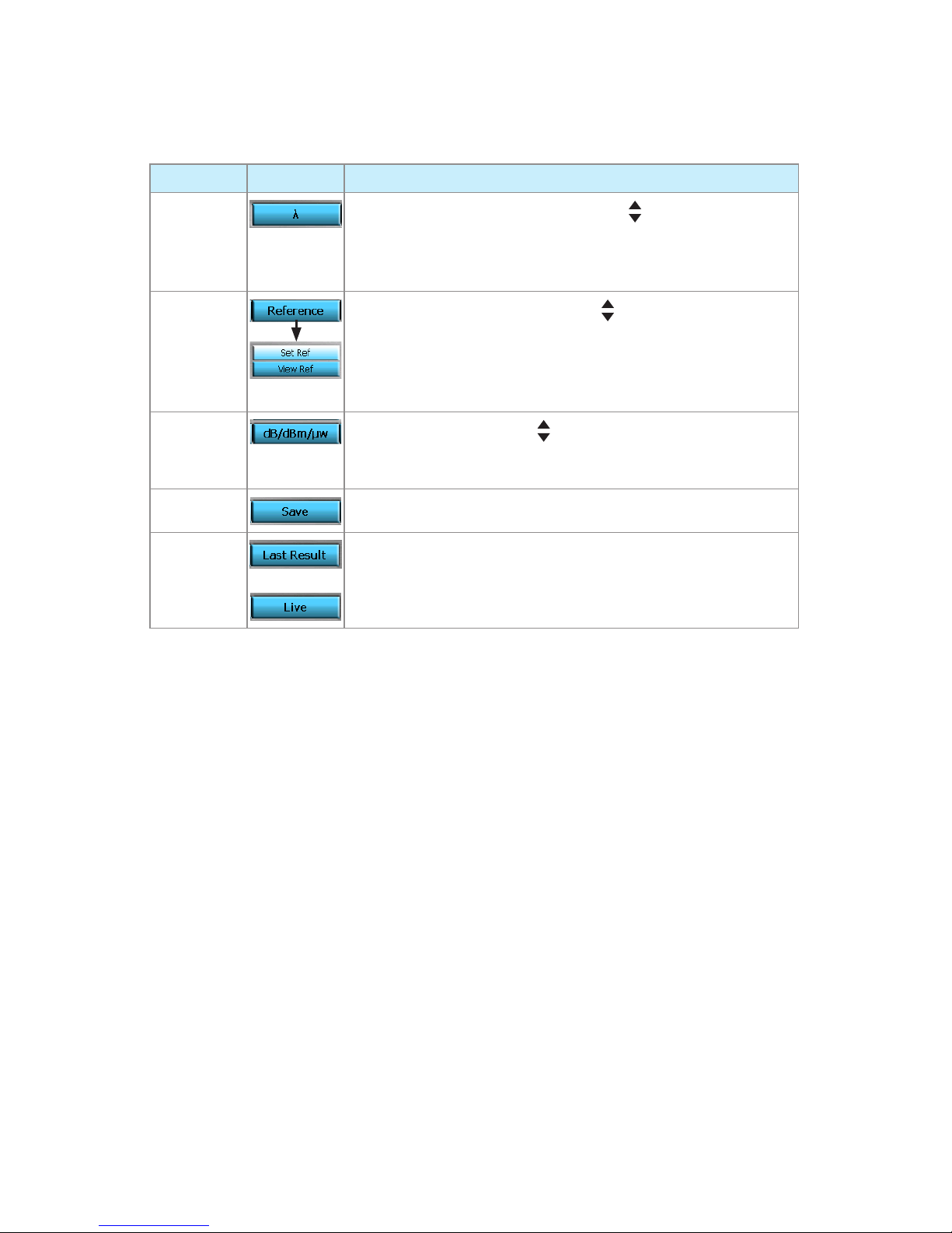
Home Page Soft Keys/Touch Screen Icons
Note: The current function of each soft key is indicated by an icon or label on the Touch Screen. If
you prefer using the Touch Screen, tap the appropriate icon or label.
KEY ICON FUNCTION
Wavelength
In CW mode: Press this key, and then use arrows to select an
available wavelength.
In Wave ID mode: this soft key is not available, the detected
wavelength(s) will be automatically displayed.
Reference
Press the Reference key, and then use arrows to select the
following keys:
[Set Ref] key to store the reference value(s) for the currently
selected/detected wavelength(s) in Loss mode.
[View Ref] key to display the saved Reference value(s).
Units
Press this key, and then use arrows to select the available units
of measure: dB, dBm, or mw. Select dB to measure Loss. Select
dBm or mw to measure Power.
Save
Press to save the currently displayed value(s).
Last Result
or
When available, press the [Last Result] key to display the last
saved value(s); the key label will turn into [Live]
Press the [Live] key to display the current/Live Loss/Power
value(s).
Page 18
18
On the equipment operating in OPM mode, press the [Reference] soft key, select [Set Ref], •
then press key.
The Reference value will be displayed briefly in dBm ( • mw).
Then the screen will toggle to display Loss values of the active wavelength(s) - nominally
•
0.00 dB.
Step II - Verify Test Jumpers
Disconnect the transmit jumper from the OPM test port.9
Note: Do not disturb the transmit jumper at the OLS end.
If necessary, change the OPM adapter cap to match the connector on the receive jumper that 10
will be connected to the OPM test port.
Note: Clean both ends of the receive jumper.
Connect the receive jumper to the OPM test port.11
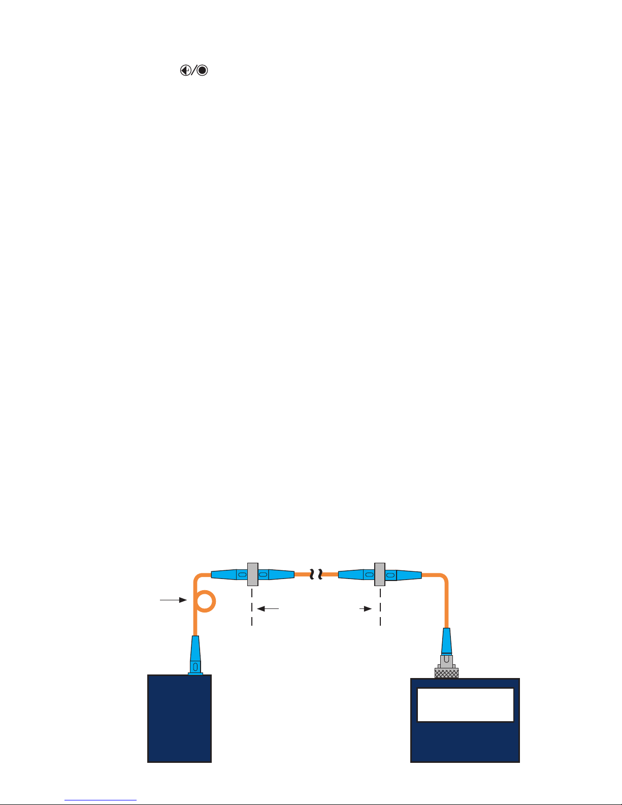
Mate the free ends of the transmit and receive jumpers using an appropriate adapter. 12
Verify that the insertion loss of this mated connector pair is under 0.75 dB, the maximum 13
allowed by the TIA and ISO (Noyes recommends 0.4 - 0.5 dB typical), as follows:
Observe
• the displayed loss level. This is the mated connector pair insertion loss of the test
jumpers in [dB].
If the insertion loss is not acceptable, disconnect the transmit and receive jumpers at the
•
adapter, clean the free ends of both test jumpers and repeat steps 12 & 13.
If the insertion loss is still not acceptable, replace both test jumpers and repeat steps 1-13. •
If the insertion loss is acceptable, disconnect the transmit and receive jumpers at the adapter.14
Move the OPM and OLS to opposite ends of the link to be tested.15
Step III - Measure Link Insertion Loss
Connect the free ends of the transmit and receive jumpers to the link under test.16
Note: Clean jumper end that connects to patch panel prior to every test.
The OPM will measure and display the insertion loss of the link under test.17
Press the [Save] key on the OPM to save the displayed measurement.18
Repeat steps 16-18 for all links to be tested at the current wavelength(s).19
OPM
OLS
2.00 dB
Link under test
Transmit jumper Receive jumper
Patch panelPatch panel
loop (SM) or
mandrel (MM)
Page 19
19
Setup: New Job Creation
The New Job utility mode is available for creating new jobs (setting up a file structure and defining
the fiber under test location: Drives, Folders, Jobs, Routes [End Locations], Cables, Test Equipment
Location, and Operators).
The New Job utility menu is accessed from the Main Menu by taping the New Job
touch
screen icon or pressing the [New Job] soft key.
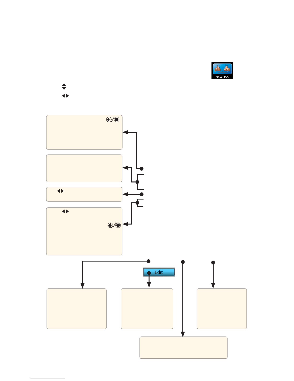
Use • arrows to navigate up/down the list of available parameters/options.
Use • arrows to scroll through the available parameters/options (if applicable).
Press the [Save]
soft key to store the
created options and
exit the New Job utility
mode
Press the [New] soft key to display editor
submenu, which allows creation of the
New Folder/Job/Route/Cable Name
Press the [Select] soft key
to access the Job Creation
screen, which allows the
user to select one of the
available Drive/Folder/Job/
Route/Cable options
Press the [New] soft key to access
the Text editor screen and create a
New Name for Folder, Job, Route,
Cable
Use arrows to toggle the End 1
and End 2 options
Use • arrows to scroll through
the list of existing operators
Press the [New] soft key or •
key to access a submenu, which
allows the user to select one of
the existing option or create a
New Operator Name
Press the [Edit] soft key
to access a submenu,
which allows the user
to select one of the
existing option or create
new option
Press the [Select] soft key or
key to display the Job Creation
screen, which allows the user to
select one of the available Drive
options
Page 20
20
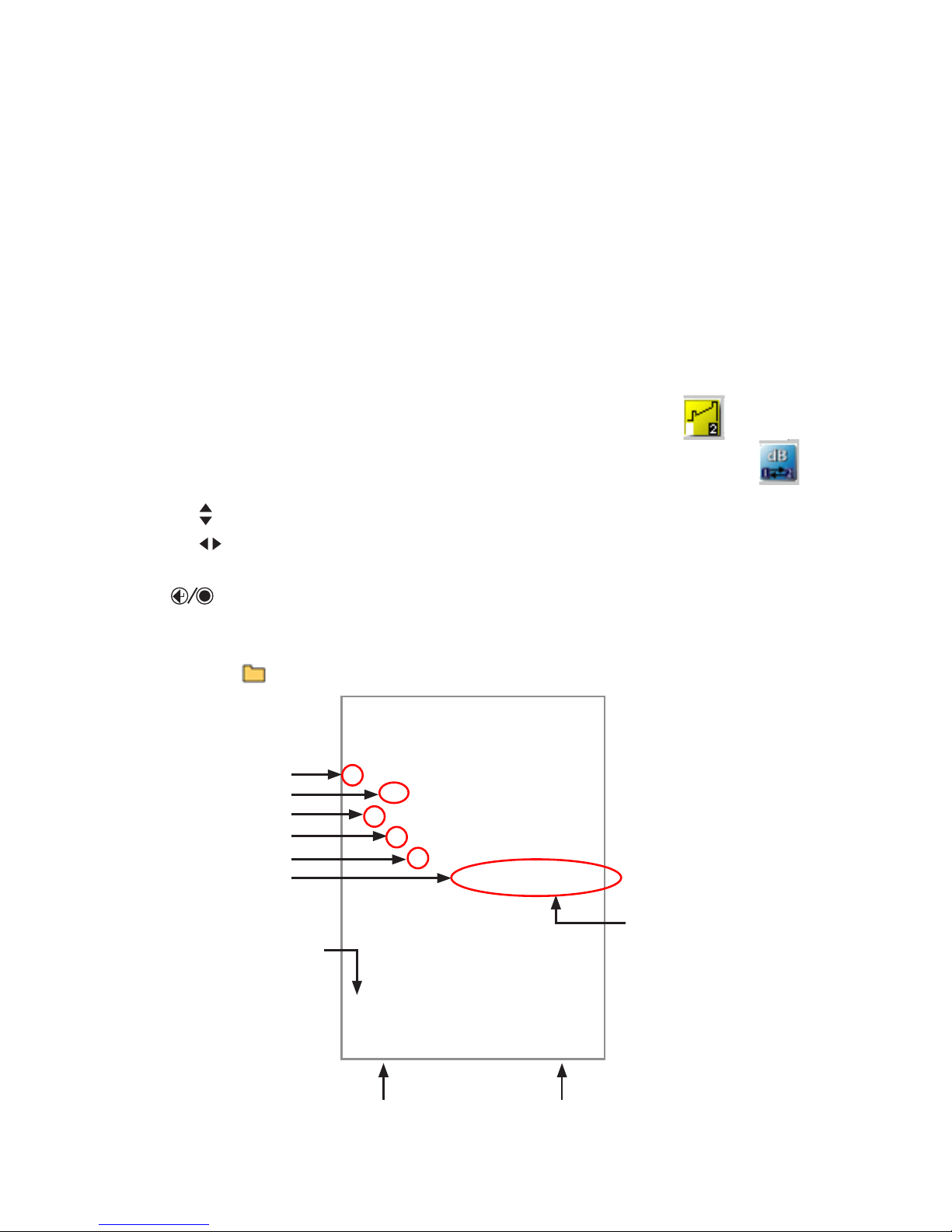
Note: See New Job Creation for a simplified means of creating new jobs (page 19).
The Results Manager menu is accessed from the Main Menu by taping the Results
touch
screen icon or pressing the [Results] soft key.
Use the Results Manager to create Jobs and Review Results. •
Use the Tools menu within the Results Manager to create or delete Jobs, Files, Folders and copy •
test data from Internal drive to USB drive.
Results Manager “File Tree” Structure
Test results are saved as files that are stored in Cable folders. Cable folders are organized into
Route, Job, and Drive folders as shown below.
OTDR test results are saved as .SOR file format and displayed on the “file tree” as
icon.
OPM power and loss readings are saved as .ATD file format and displayed on the “file tree” as
icon.
Use
• arrows to navigate up/down the list of folders and files.
Use • arrows to expand/contract the selected Drive/Folder/Job/Route/Cable.
To open saved test results, navigate to the desired test file, and then press the [Open] soft key or •
key.
Use the Tools menu within the Results Manager to create or delete Jobs, Files, Folders and copy •
test data from Internal drive to USB drive.
Note: Folders
are not required to store results: Job, Route, and Cables.
Setup: Results Manager
This field displays path/
name of the selected file
In this example, file
contains both the OTDR
and OPM test results.
Press to display selected test results
Folder
Drive
Job
Route
Cable
Fiber Test Results
Press to display Tools menus.
Tools menus will vary depending on the selected level
in the file tree structure as shown on the next page).
Page 21
21
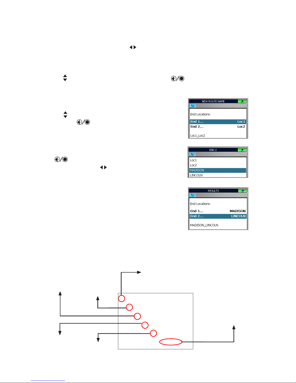
From the Results Manager page, use 1 arrows to highlight the desired Drive where test results
will be saved.
Press the [Tools] soft key to display the Tools menu (
2 Tools menus will vary depending on the
selected level in the file tree structure as shown below.
Use
3 arrows to highlight the [New Job] option and press key to display the Text Editor
(see page 29 for details on how to use it). Enter a name for the New Job. Press OK to return to
the Results Manager page.
Tools menus in the file tree structure
With the created New Job highlighted, press [Tools] > [New 4
Route]. The Route page will be displayed.
Use 5 arrows to highlight [End 1...] or [End 2...]. Press
[Select] or key to display the End Locations sub-page.
To create new End Location(s), press the [New] soft key. 6
Using the displayed Text Editor, create new End name. Press
OK.
Create as many End Names as needed for a Job and press 7
key to return to the Route page.
From Route page, use 8 arrows to select Ends for the
Route. Press OK.
With the created Route highlighted, press [Tools] >[New 9
Cable].
Using the displayed Text Editor, enter a name for the new 10
Cable. Press OK.
If needed, create more Jobs, Routes, Cables.
With the desired Cable selected, press Main Menu.11
Select a Test mode to begin testing the selected Cable. 12
Before pressing [Test], verify test setup on the Job Settings
page within the selected Test mode.
End Locations Sub-page
New Route Selected
Route Page
Job Creation in Results Manager
Job
Drive
Folder
Route
Cable
Test Result
Depends on availability/
selected results
Page 22
22
Job Selection from a Test Mode
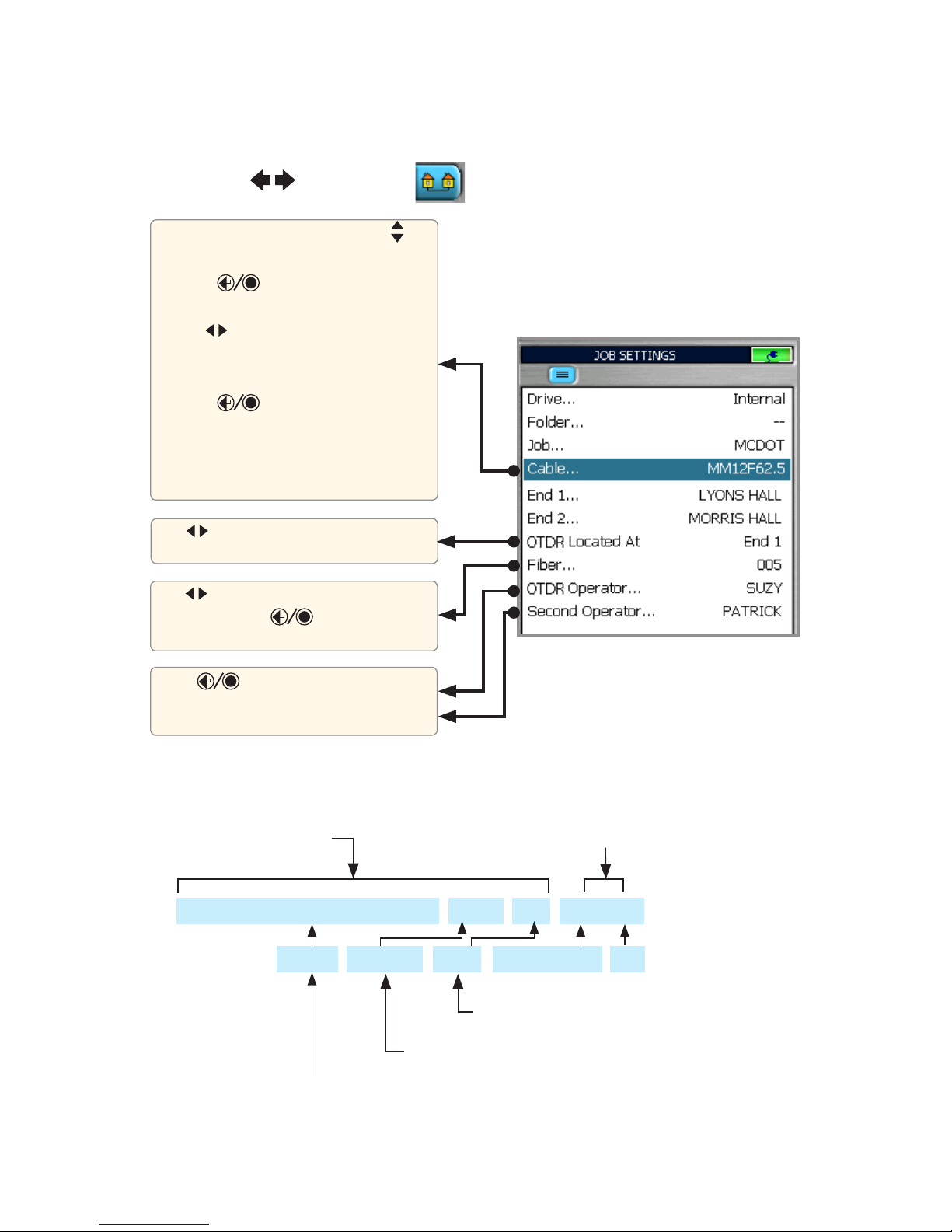
A Job is selected from the Job Settings page, which is accessed from each test mode. Within each
test mode, use
tab keys to select tab and display the Job Settings page.
Use arrows to increase/decrease fiber
number, or press key to display a
numerical editor to set
Use arrows to display your equipment
location (End 1 or End 2)
Press key to display submenu to
define Operators’ IDs using [Edit] and
[New] options
From the Job Settings page, use 1
arrows to highlight Cable...
Press 2 key to display the Results
Manager page.
Use
3 arrows to select the Cable
within Drive > Folder > Job > Route
you want to test and save results.
Press 4 key to return to the
Job Settings page and verify Job
Parameters, equipment Location, test
Operators, and starting Fiber number
information.
Name Format (see screen above) as seen on a PC
Fiber number - user set, will auto increment
Wavelength indicator- added automatically by OTDR Name Format – user set
Route-CableID-Fiber_Wavelength.sor
Route is made up of the two end names End 1 and End 2.
They are ordered in the file name such that the first end - End 1 is
where the OTDR is located or the “Near end”, followed by the other
end - End 2 or the “Far end”.
LYONS HALL-MORRIS HALL-SM4K_005_S15.sor
Cable ID – user set
as follows:
.M85 for 850 nm
.M13 for 1300 nm
.S13 for 1310 nm
.S15 for 1550 nm
Page 23
23
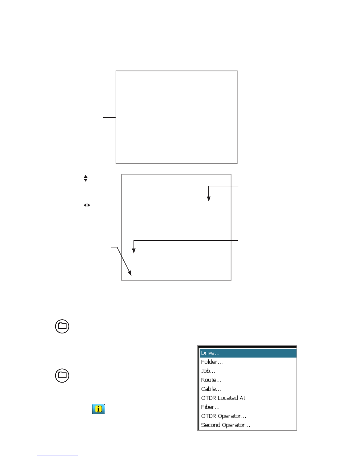
Opening a Trace File for Review
Save
After completing a test, press the
Save key to save file in current folder
with name established in the setup
process.
Save-As
To change the folder, job name, or
other parameter after a test has been
completed, go to the Job Information
tab and make the changes.
Once satisfied, press the Save key.
Changes only apply to the current test.
Saving Test Results
Use the • arrows to
navigate up/down the
list of folders/files
Use the • arrows
to expand/contract
the selected Drive/
Folder/Job/Route/
Cable
To open saved test •
results, navigate to
the desired file, and
then press [Open]
[Results] soft key
Access Results Manager from the Main Menu by pressing the [ Results] soft key.
This field displays
path and name of the
selected file
In this example, file
contains both the
OTDR and OPM test
results
Page 24
24
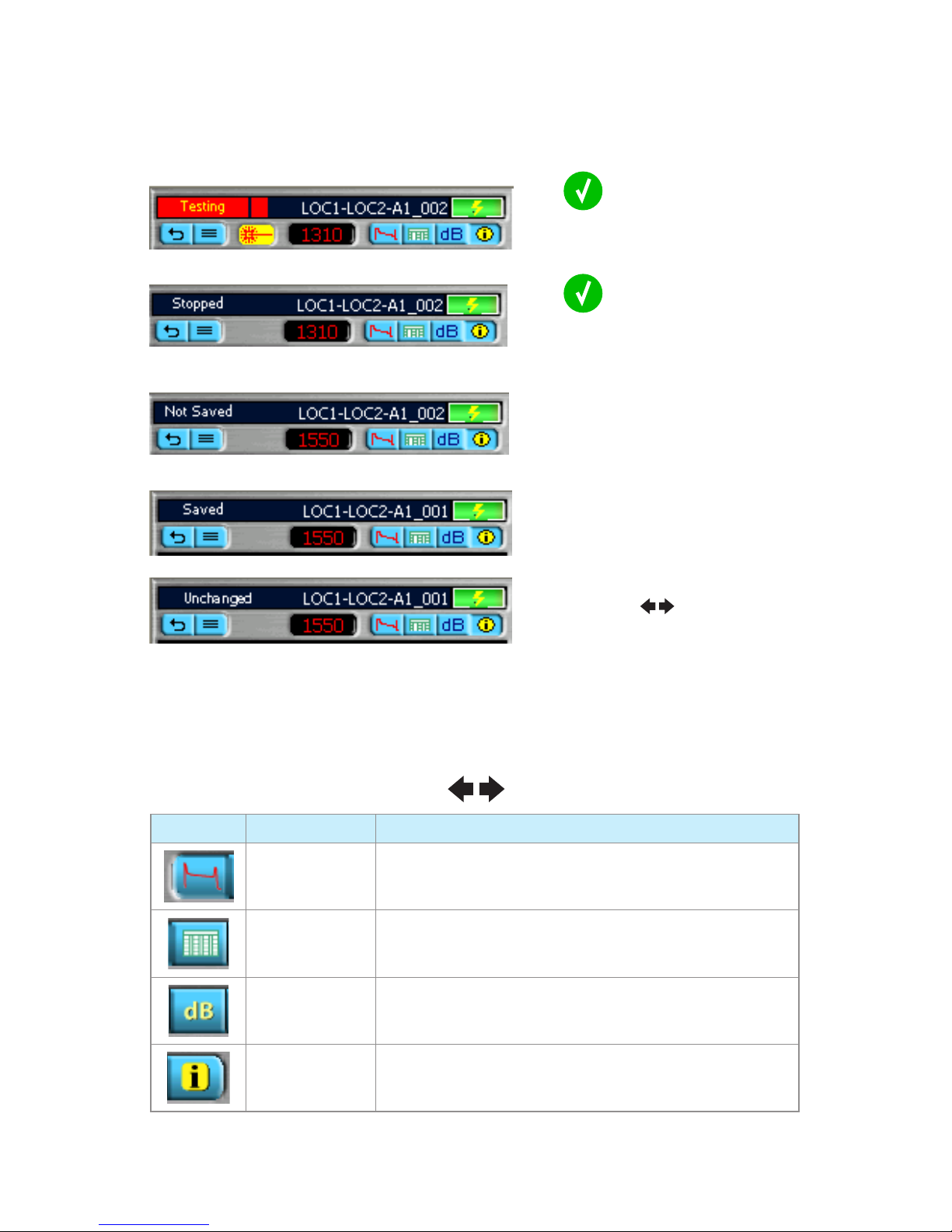
Press
to start Test
OTDR header is [Testing]
Press
to stop Test
OTDR header is [Stopping] followed by
[Stopped]
When test is done, the OTDR header is
[Not Saved]
Open saved trace from the Results
Manager and use
keys to go
between views without making changes.
The OTDR header is [Unchanged].
If changes are made, the OTDR header is
[Not Saved].
After test is saved, the OTDR header is
[Saved]
Page Tabs (navigate using keys)
PAGE ICON PAGE NAME DESCRIPTION
Trace page Displays OTDR trace, setup, A/B cursor data, Loss Method,
Loss, Reflectance
Event Table OTDR trace; event Location, Type, Reflectance, Loss, event
Pass/Fail (if turned On)
Summary page Displays OTDR trace, Link Length, ORL, Loss, link Pass/Fail (if
turned On)
Job Information
page
Displays setup parameters of the currently displayed trace
Running Tests & Viewing Results
Page 25
25
Trace Page Features
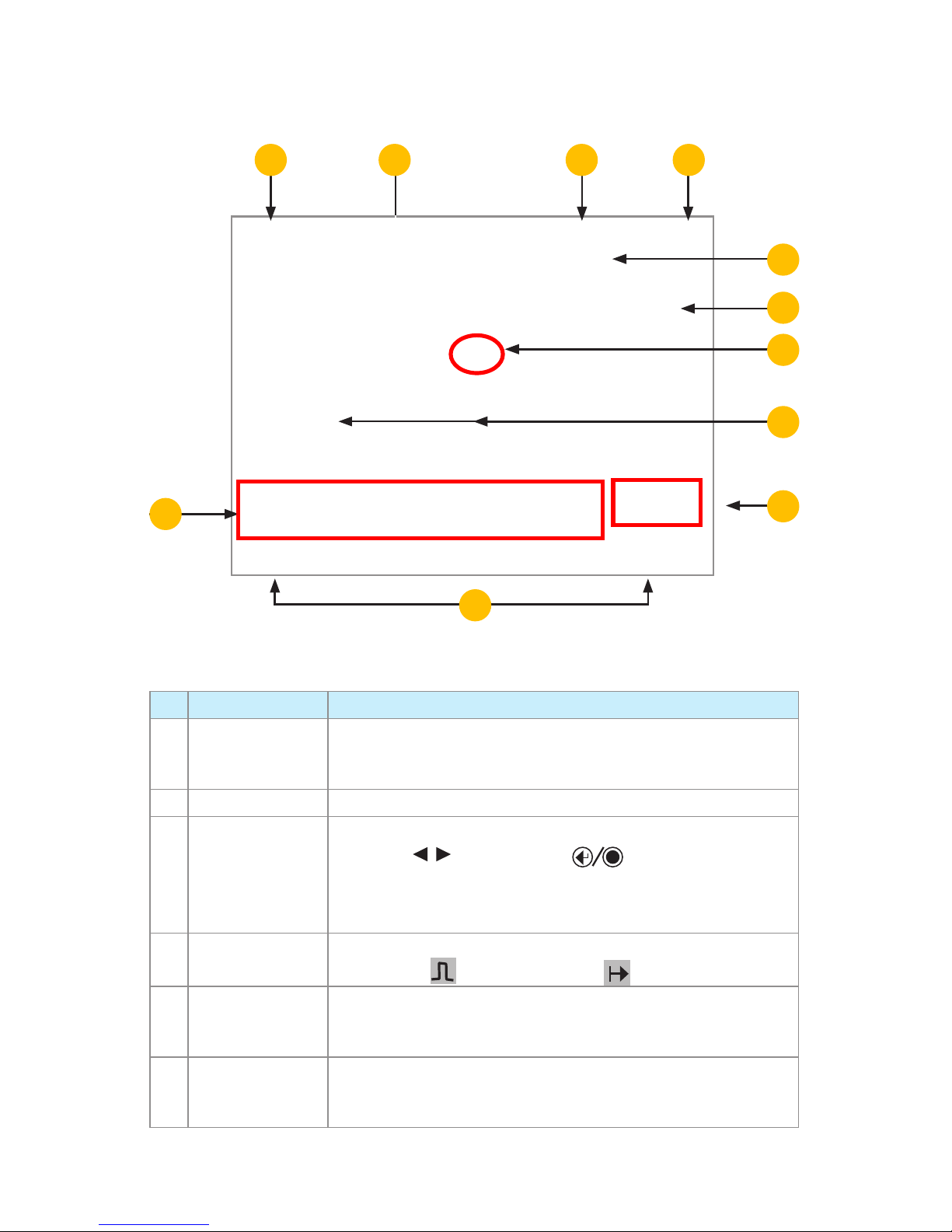
REF FEATURE DESCRIPTION
1 Trace This is a graph of insertion loss vs. distance. The vertical axis shows
loss in dB. The horizontal axis shows distance in user-selected
distance units.
2 LSA adjust lines Available depending on the selected Loss Method.
3 Cursors Used to measure loss and distance. The active cursor can be moved
by pressing
arrows. Press the key to toggle between
the A and B cursors.
Note: Active cursor is displayed as a bold line, inactive cursor is
displayed as a dashed line.
4 Test settings data
field
This eld displays various test settings data as follows: distance • dB
per division •
pulse width setting • Range value
5 Soft function key
labels
Soft function keys are located on the front panel. The label shown on
the display above each key indicates the current use of each function
key.
6 Test results field This field displays various test results as follows: Loss Method, A and
B cursor location, distance from A to B in user-selected distance units,
measured loss and reflectance, and event data.
Trace Page Features
2
3
4
5
6
1
11
10987
Page 26
26
Soft Keys
SOFT KEY DESCRIPTION AND FUNCTION
For the dual-wavelength test, press this key to toggle between the test
results.
Press this key to display the [Zoom Adjust] view. •
Use • arrows to adjust the Vertical zoom level.
Use • arrows to adjust the Horizontal zoom level.
When done, press OK to return to the Trace window. •
Press [Unzoom] to display trace at the original magnification level. The •
soft key label changes to [Rezoom].
Press [Rezoom] to return to the previously set magnification level. •
Press to display the Loss Method Menu. •
Use • arrows to select the desired Loss Method as follows: Two Point,
Single, Multiple, Fiber Attenuation, Start, End.
Press to display the LSA Tools Menu. •
Use • arrows to select the desired option as follows: LSA Adjust, Add
Event, Reset Handles.
When done, press the [OK] soft key to close the Loss Adjust Window. •
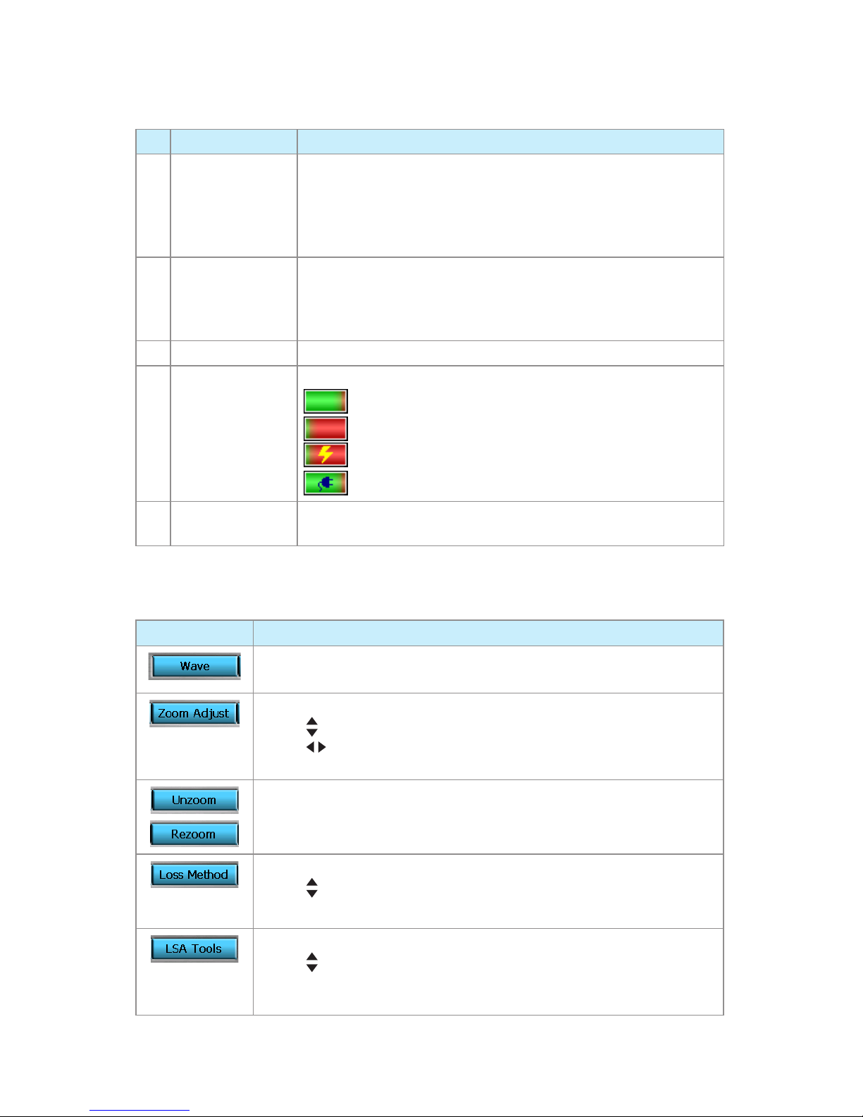
REF FEATURE DESCRIPTION
7
Test status
Displays test status labels as follows:
Testing - indicates test in progress
Stopped - test is interrupted
Not Saved - the displayed test results are not saved
Saved - the displayed test results are saved
8 Wavelength field Displays test wavelengths of the currently displayed trace.
For the dual-wavelength test, press the [Wave] soft key to toggle
between test results.
Note: the currently selected wavelength is displayed in RED color.
9 File name field Displays file name of the currently displayed trace.
10 Battery indicator Displays estimated battery status as follows:
Green - fully charged
Red - discharged
Charging - AC connected
Fully Charged - AC connected
11 Trace page tabs Select a tab to display the corresponding View (see page 25 for
details)
Trace Page Features
Page 27
27
Event Table & Summary Results
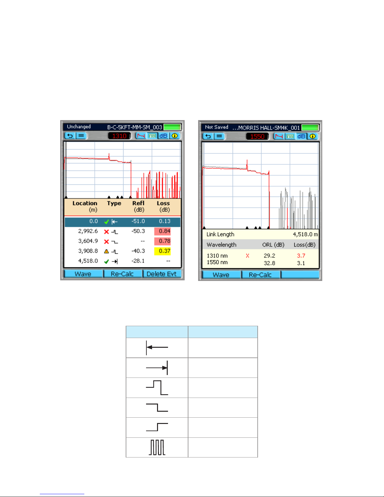
Event Table & Summary Results are generated together
Set Mode to Full Auto or set Mode to Expert and Events (Event Settings) to Auto.1
From the Event Table or Summary page, press the [Calc] soft key if no Event Table or Summary 2
page was created. Or press the [Re-Calc] soft key to generate a new Event Table or Summary
page if you changed the GIR or BC on the Job Settings page.
EVENT ICON EVENT TYPE
Start of Fiber Under Test
End of Fiber Under Test
Reflective Event
Non-Reflective Event
Gainer
Multiple Event
Event Icons and Types
Shown with Pass/Fail Thresholds enabled Shown with Pass/Fail Thresholds enabled
Page 28
28
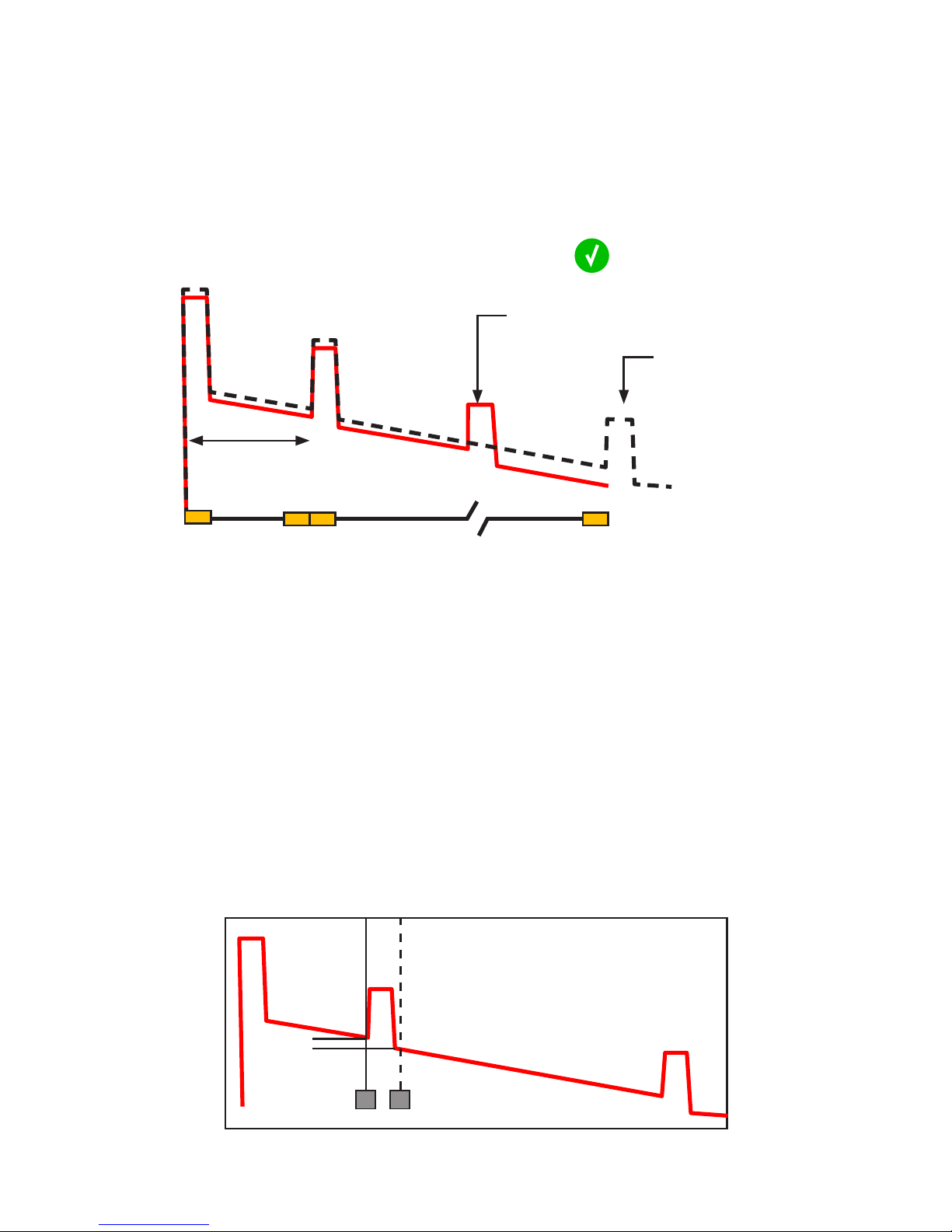
Fault Locating: Full Auto
Select Full Auto mode1
Clean and Connect launch cable2
Select Test Port: SM or MM3
Select Fiber Type4
Measuring Loss on an OTDR Trace
Select Launch Cable: Noyes (1km), Noyes 5
(500m), Noyes (150m), None, User
In General Settings: Set Distance Units: m, ft, kft, 6
km, mi
Press Test key
7
Two Point A/B Measurement
cursor just after the tail of the last event.
Position the left cursor [A] at the start of 1
the event
Position the right cursor [B] beyond the 2
event where the trace returns to a constant
slope
Read the insertion loss (Loss: in dB) 3
measurement
An OTDR trace shows relative power vs.
distance. The insertion loss (IL) between any
two points (A to B) on the optical fiber link
under test equals the trace level at A minus the
trace level at B.
To measure the end-to-end loss of a link, use a
launch and receive cable and put the [A] cursor
before the first event in the link and the [B]
A B
IL
Launch Cable
Break
Trace displaying Fault
Expected trace
Shows IL of an event
Page 29
29
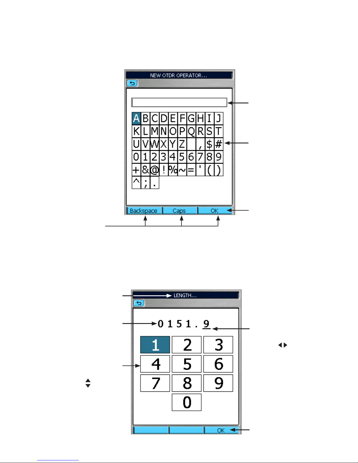
Text Editor
Numerical Editor
Numeric Touch Pad
(Tap with stylus or
use arrows to
increment/decrement
the selected value)
Editable text field
Touch Pad of
alphanumeric
characters
(Tap with stylus
or use Arrow and
Enter keys)
Soft key labels
Press when done
Selection cursor
Move by
pressing
arrows
Parameter name
Editable numeric field
Press when done
Page 30

30
Transferring Files
From OTDR via USB Function Port to PC
To transfer files from your OTDR to a PC using a USB cable, perform the following:
Connect your OTDR to a PC using the supplied mini-USB to USB cable. 1
Note: If your PC requests new USB drivers, install the CD-ROM that comes with your OTDR,
which contains the needed drivers. This step only needs to be performed the first time you
connect your OTDR and PC together.
If your PC pops up a dialog box asking if you want to set up a new Partnership, select No (the 2
OTDR should always be a ‘guest’).
Open My Computer > •
Mobile Device > File Storage > Internal folder.
or
Open My Computer > Mobile Device > USB folder. •
Page 31

31
Recommended Accessories
Fiber Optic Test Cables and Jumpers
Fiber optic test cables are necessary to connect an OTDR to the fiber under test ( FUT). Test cables
must have the same core and cladding size as the FUT. The connector at one end of the test cable
must mate with the appropriate optical port on the OTDR. The connector on the other end must
mate with the fiber optic link under test.
Launch and Receive cables are required to measure the insertion loss and reflectance of the nearend and far-end connectors respectively, of the fiber link being tested. Noyes Fiber Rings may be
used as Launch and Receive cables. Fiber Rings with a variety of lengths and connector styles are
available from AFL Telecommunications. The table on the next page will help in selecting the right
test jumpers or cables for testing.
Fiber Optic Test Cables and Jumpers Selection Chart
TO DO THE FOLLOWING TEST YOU WILL NEED THE FOLLOWING ACCESSORIES
To connect your OTDR to the
fiber link under test
To terminate far-end of the
fiber link under test
• Fault locate - find a break
• Measure link length
Test Jumper (1-2 m typical) None
• M
easure near-end connector
loss
• Measure near-end connector
reflectance
Launch cable
(such as a Noyes 150m,
500m, 1000m Fiber Ring)
None
• Measure near-end connector
loss and reflectance
• Measure far-end connector
loss and reflectance
• Measure end to end link loss
and optical return loss
Launch cable
(such as a Noyes 150m,
500m, 1000m Fiber Ring)
Receive cable
(such as a Noyes 150m,
500m, 1000m Fiber Ring)
Fiber Ring (FR) Selection Chart
FR LENGTH FIBER TYPE FIBER UNDER TEST LIMITS COMMENTS
150m (492ft) Multimode All runs 30m to 3km or 2mi Multimode runs are < 3km or 2mi
150m (492ft) Single-mode All P W's up to 1,000 ns or 1µs * PW of 1µs = pulse length of 100m
500m (1,640ft) Single-mode All PW's up to 3,000ns or 3µs PW of 3µs = pulse length of 300m
1km (3,281ft) Single-mode All PW's < 5,000ns or 5µs PW of 5µs = pulse length of 500m
5km (16,405ft) Single-mode All PW's up to 20,000ns or 20µs PW of 20µs = pulse length of 2km
* A PW of 1,000ns (1µs) requires reflective events lower than -45 dB of ORL to be used with the 150
meter fiber rings.
Page 32

32
Specifications
Continued on the next page
M700 Single-mode OTDR
OTDR SPECIFICATIONS DUAL-WAVE OTDR TRIPLE-WAVE OTDR
Emitter Type Laser
Safety Class Class I FDA 21 CFR 1040.10 and 1040.11, IEC 60825-1: 2007-03
Center Wavelengths 1310/1550 nm 1310/1550/1625 nm
Wavelength Tolerance ± 25/25 nm ± 25/25/10 nm
Dynamic Range (SNR = 1) 40/38 dB 40/38/38 dB
Event Dead Zone
0.8 m
1
0.8 m
1
Attenuation Dead Zone
4.5 m
2
4.5 m
2
Pulse Widths 5, 10, 30, 100, 300 ns; 1, 3, 10, 20 ms
Range Settings 250 m to 256 km
Sampling Points Max. 64,000 points
Minimum Data Point Spacing 0.125 m
Group Index of Refraction (GIR) 1.4000 to 1.6000
Distance Uncertainty (m)
3
± (1 + 0.0005% x distance + data point spacing)
Linearity
4
± 0.05 dB/dB
Trace File Format SR-4731 (GR-196-CORE Appendix A & B and SR-4731)
Trace File Storage Media
Internal flash memory
USB flash drive (2 USB host ports)
Downloadable from OTDR directly to PC
Trace File Storage Capacity Internal 1000 fibers
Data Transfer to PC USB
OTDR Modes Full Auto, Real Time, Expert
Tool Free Adapters SC/ST/FC/LC
1 Typical distance between the two points 1.5 dB down each side of an event with reflection < -45 dB for SM
and <-40 dB (unsaturated) for MM using a 5 ns pulse width.
2 Typical distance from event location to point where trace is within 0.5 dB of backscatter caused by an event
with reflection < -45 dB for SM and <-40 dB (unsaturated) for MM using a 5 ns pulse width.
3 Does not include GIR uncertainty.
4 Typical.
Page 33
33
Specifications
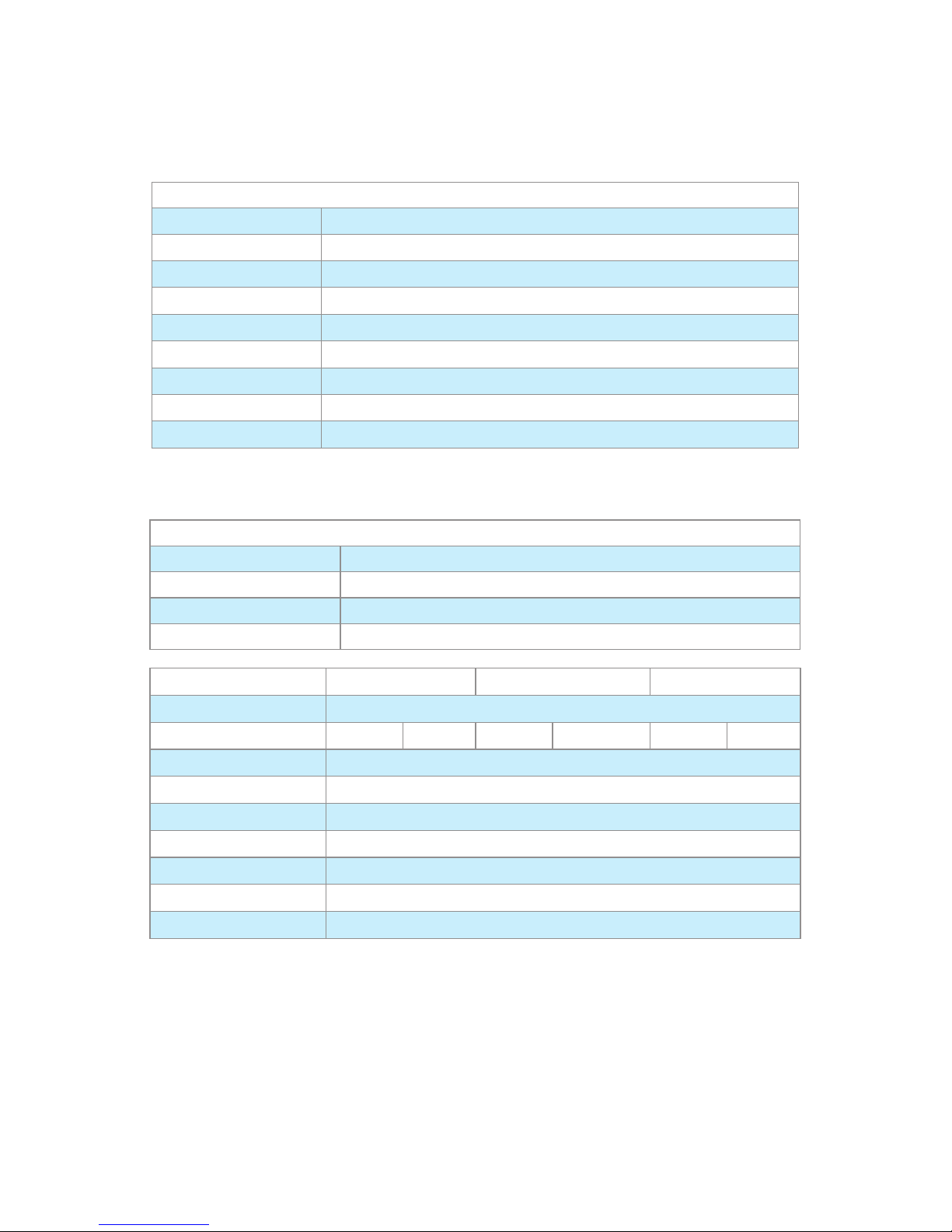
M700 Single-mode OTDR Specifications (continued)
POWER METER SPECIFICATIONS
Calibrated Wavelengths
850, 980,
1300, 1310, 1490, 1550, 1625 nm (displays up to 3 simultaneously)
Detector Type
Filtered InGaAs detector
Measurement Range (dBm)
+26 to -50 dBm
Accuracy
1
±0.25
Measurement Units
dB, dBm, mW
Wavelength ID
2
Yes
Set Reference
Yes
Data Storage
Yes
Tone Detection
270 Hz, 330 Hz, 1 kHz, 2 kHz
1 Accuracy measured at 25ºC and -10 dBm per N.I.S.T. standards.
2 Automatic wavelength identification and switching when used with Noyes Wave ID Series Light Sources.
VISUAL FAULT LOCATOR SPECIFICATIONS
Emitter Type Laser
Safety Class Class II FDA 21 CFR 1040.10 and 1040.11, IEC 60825-1: 2007-03
Wavelength 650 nm
Output Power (nominal) 0.8 mw
GENERAL
SINGLE-MODE OTDR LONG RANGE QUAD OTDR QUAD OTDR
Display 16.51 cm (6.5 in), color, transflective (indoor/outdoor) touch screen display
Anti-Reflective (AR) Coating Yes
Yes
Yes Yes
— —
Size 190.5 x 269.2 x 69.8 mm (7.5 x 10.6 x 2.75 in)
Weight 2.36 kg ( 5.22 lb)
Operating Temperature -10 to +50°C, 0 to 90% RH (non-condensing)
Storage Temperature -20 to +60°C, 0 to 90% RH (non-condensing)
Power Rechargeable Li-Ion or AC power adapter
Battery Life
1
> 8 hours continuous OTDR testing
Recharge Time
2
4 hours
1 Typical, depending on display brightness.
2 Typical, from fully discharged to fully charged state, unit may be operating.
External battery charger available.
Page 34
34
Specifications
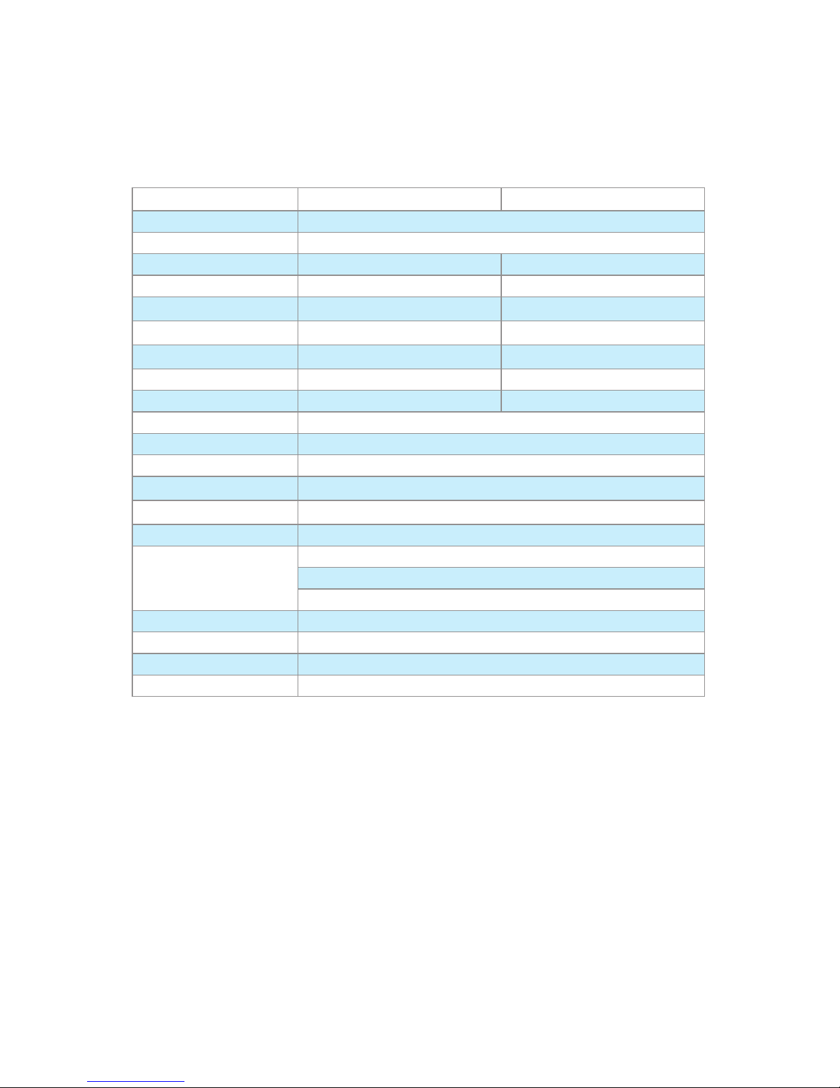
M700 Long Range QUAD OTDR Specifications
All specifications valid at 25°C unless otherwise specified
Continued on the next page
OTDR SPECIFICATIONS MULTIMODE OTDR SINGLE-MODE OTDR
Emitter Type Laser
Safety Class Class I FDA 21 CFR 1040.10 and 1040.11, IEC 60825-1: 2007-03
Center Wavelengths 850/1300 nm 1310/1550 nm
Wavelength Tolerance ± 25/25 nm ± 25/25 nm
Dynamic Range (SNR = 1)
24/24 dB
1
39/37 dB
Event Dead Zone
0.9 m
2
0.9 m
2
Attenuation Dead Zone
4.5 m
3
4.5 m
3
Pulse Widths 5,10, 30, 100, 300 ns; 1ms 5,10, 30, 100, 300 ns; 1, 3, 10, 20 ms
Range Settings 250 m to 64 km 250 m to 256 km
Sampling Points Max. 64,000 points
Minimum Data Point Spacing 0.125 m
Group Index of Refraction (GIR) 1.4000 to 1.6000
Distance Uncertainty (m)
4
± (1 + 0.0005% x distance + data point spacing)
Linearity
5
± 0.05 dB/dB
Trace File Format SR-4731 (GR-196-CORE Appendix A & B and SR-4731)
Trace File Storage Media
Internal flash memory
USB flash drive (2 USB host ports)
Downloadable from OTDR directly to PC
Trace File Storage Capacity Internal 1000 fibers
Data Transfer to PC USB
OTDR Modes Full Auto, Real Time, Expert
Tool Free Adapters SC/ST/FC/LC
1 62.5µm fiber.
2 Typical distance between the two points 1.5 dB down each side of an event with reflection < -45 dB for SM
and <-40 dB (unsaturated) for MM using a 5 ns pulse width.
3 Typical distance from event location to point where trace is within 0.5 dB of backscatter caused by an event
with reflection < -45 dB for SM and <-40 dB (unsaturated) for MM using a 5 ns pulse width.
4 Does not include GIR uncertainty.
5 Typical.
Page 35
35
Specifications
M700 Long Range QUAD OTDR Specifications (continued)
POWER METER SPECIFICATIONS
Calibrated Wavelengths
850, 980,
1300, 1310, 1490, 1550, 1625 nm (displays up to 3 simultaneously)
Detector Type InGaAs 2mm
Measurement Range (dBm) +6 to -70 dBm
Accuracy
1
±0.25
Measurement Units dB, dBm, mW
Wavelength ID
2
Yes
Set Reference Yes
Data Storage Yes
Tone Detection
270 Hz, 330 Hz, 1 kHz, 2 kHz
1 Accuracy measured at 25ºC and -10 dBm per N.I.S.T. standards.
2 Automatic wavelength identification and switching when used with Noyes Wave ID Series Light Sources.
VISUAL FAULT LOCATOR SPECIFICATIONS
Emitter Type Laser
Safety Class Class II FDA 21 CFR 1040.10 and 1040.11, IEC 60825-1: 2007-03
Wavelength 650 nm
Output Power (nominal) 0.8 mw
GENERAL
SINGLE-MODE OTDR LONG RANGE QUAD OTDR QUAD OTDR
Display 16.51 cm (6.5 in), color, transflective (indoor/outdoor) touch screen display
Anti-Reflective (AR) Coating Yes
Yes
Yes Yes
— —
Size 190.5 x 269.2 x 69.8 mm (7.5 x 10.6 x 2.75 in)
Weight 2.36 kg ( 5.22 lb)
Operating Temperature -10 to +50°C, 0 to 90% RH (non-condensing)
Storage Temperature -20 to +60°C, 0 to 90% RH (non-condensing)
Power Rechargeable Li-Ion or AC power adapter
Battery Life
1
> 8 hours continuous OTDR testing
Recharge Time
2
4 hours
1 Typical, depending on display brightness.
2 Typical, from fully discharged to fully charged state, unit may be operating.
External battery charger available.
Page 36

36
M700 QUAD OTDR Specifications
All specifications valid at 25°C unless otherwise specified
Specifications
OTDR QUAD OTDR
MULTIMODE SINGLE-MODE
Emitter Type Laser
Safety Class Class I FDA 21 CFR 1040.10 and 1040.11, IEC 60825-1: 2007-03
Center Wavelengths 850/1300 nm 1310/1550 nm
Wavelength Tolerance ± 20/30 nm ± 20/30 nm
Dynamic Range (SNR = 1)
22 dB
1
26 dB
Event Dead Zone
1.5 m
2
1.5 m
2
Attenuation Dead Zone
9 m
3
9 m
3
Pulse Widths 10, 30, 100, 300 ns;
1 ms
10, 30, 100, 300 ns;
1, 3, 10 ms
Range Settings 250 m to 64 km 250 m to 208 km
Sampling Points Max. 16,000 points
Minimum Data Point Spacing 0.25 m
Group Index of Refraction (GIR) 1.4000 to 1.6000
Distance Uncertainty (m)
4
± (1 + 0.005% x distance + data point spacing)
Linearity
5
± 0.05 dB/dB
Trace File Format
SR-4731 (GR-196-CORE Appendix A & B and
SR-4731)
Trace File Storage Media
Internal flash memory
USB flash drive (2 USB host ports)
Downloadable from OTDR directly to PC
Trace File Storage Capacity Internal 1000 fibers
Data Transfer to PC USB
OTDR Modes Full Auto, Real Time, Expert
Tool Free Adapters SC/ST/FC/LC
1 62.5µm fiber.
2 Typical distance between the two points 1.5 dB down each side of an event with reflection < -45 dB for SM
and <-40 dB (unsaturated) for MM using a 10 ns pulse width.
3 Typical distance from event location to point where trace is within 0.5 dB of backscatter caused by an event
with reflection < -45 dB for SM and <-40 dB (unsaturated) for MM using a 10 ns pulse width.
4 Does not include GIR uncertainty.
5 Typical.
Page 37
37
Specifications
M700 QUAD OTDR Specifications (continued)
POWER METER SPECIFICATIONS
Calibrated Wavelengths
850, 980,
1300, 1310, 1490, 1550, 1625 nm (displays up to 3 simultaneously)
Detector Type InGaAs 2mm
Measurement Range (dBm) +6 to -70 dBm
Accuracy
1
±0.25
Measurement Units dB, dBm, mW
Wavelength ID
2
Yes
Set Reference Yes
Data Storage Yes
Tone Detection
270 Hz, 330 Hz, 1 kHz, 2 kHz
1 Accuracy measured at 25ºC and -10 dBm per N.I.S.T. standards.
2 Automatic wavelength identification and switching when used with Noyes Wave ID Series Light Sources.
VISUAL FAULT LOCATOR SPECIFICATIONS
Emitter Type Laser
Safety Class Class II FDA 21 CFR 1040.10 and 1040.11, IEC 60825-1: 2007-03
Wavelength 650 nm
Output Power (nominal) 0.8 mw
GENERAL
SINGLE-MODE OTDR LONG RANGE QUAD OTDR QUAD OTDR
Display 16.51 cm (6.5 in), color, transflective (indoor/outdoor) touch screen display
Anti-Reflective (AR) Coating Yes
Yes
Yes Yes
— —
Size 190.5 x 269.2 x 69.8 mm (7.5 x 10.6 x 2.75 in)
Weight 2.36 kg ( 5.22 lb)
Operating Temperature -10 to +50°C, 0 to 90% RH (non-condensing)
Storage Temperature -20 to +60°C, 0 to 90% RH (non-condensing)
Power Rechargeable Li-Ion or AC power adapter
Battery Life
1
> 8 hours continuous OTDR testing
Recharge Time
2
4 hours
1 Typical, depending on display brightness.
2 Typical, from fully discharged to fully charged state, unit may be operating.
External battery charger available.
Page 38

38
Cleaning Tips
Clean Test Cables and FUT
It is important to keep connector end-faces on the launch and receive cables and those on the Fiber
Under Test (FUT ) clean, to ensure accurate measurements and operation.
IMPORTANT! Inspect optical connectors after cleaning to ensure cleaning was successful and to
verify the end-face is not damaged (cracked, pitted, etc.).
CAUTION! Never view a live fiber. Laser radiation is harmful to eyes.
Follow your company’s approved cleaning procedures.
AFL recommends cleaning test cables using a Cletop cassette cleaner or a One-Click Cleaner.
Cleaning the Optical Ports
CAUTION! Before conducting the following procedures be sure to have the OTDR turned OFF.
Cleaning the OTDR and VFL optical ports without removing the adapters
AFL One-Click Cleaner method
Remove the protective dust cover from the tip of the One-Click Cleaner. •
Insert the tip of the One-Click Cleaner into the optical port adapter and gently press the body of
•
the One-Click Cleaner until an audible “click” is heard.
Remove the One-Click Cleaner.
•
AFL FCC2 fluid and CCT stick method
Lean a can of FCC2 back (30°), press the button on FCC2 to fill the well. •
Dip a CCT stick into the well of the FCC2 to dampen the tip with optical cleaning fluid. •
Place the damp tip over the ferrule to be cleaned.
•
Rotate the tip clockwise 10 revolutions while applying varying pressure to create a gentle •
pumping action where the tip contacts the ferrule.
Discard the CCT stick after using both tips.
•
Page 39

39
Cleaning the optical ports with adapters removed
Removing connector adapters for cleaning and inspection
To access the OTDR Port
Rotate the adapter base counterclockwise approximately four times. •
Pull the adapter directly out away from the universal adapter mount to expose the ferrule. •
To access the VFL Port
Unscrew the adapter counterclockwise and pull the adapter straight out to expose the ferrule.
To access the OPM Port
Unscrew the adapter cap from the adapter cap mount.
Cleaning the Exposed Ferrule or the OPM port
Use lint-free optical cleaning wipes such as AFL FiberWipes and optical quality cleaning fluid such as
AFL FCC2 connector cleaning fluid.
Note: if using isopropyl alcohol (IPA), be sure to use 99% pure IPA that has not been contaminated.
Dampen a portion of the wipe with the cleaning fluid.
1
Gently wipe the exposed ferrule (OPM port) starting with the wet section of the wipe and pulling 2
it to the dry section.
Note: • Starting with the wet cleaning and finishing in the dry improves cleaning action,
reduces static buildup, and finishes with the end-face dry.
Cleaning the adapters
Method 1:
Insert a Cletop adapter cleaning stick into the sleeve of the adapter and rotate 10 times. 1
Remove.2
After cleaning the adapter, replace the adapter over the ferrule; centering it onto the alignment 3
pin.
Tighten the adapter base.4
Method 2:
Use a can of filtered compressed air (held vertically), blow out any contaminates from the 1
adapter.
After cleaning the adapter, replace the adapter over the ferrule; centering it onto the alignment 2
pin.
Tighten the adapter base.3
Page 40

40
FAQs
Can I save traces for viewing later?
Yes. There is a dedicated Save key. In the Main Menu “File tab”, set up the location/folder (Internal
or USB) to save the file, the file naming format, and fiber number. The fiber number will automatically
increment after each trace is saved.
What is the advantage of the Expert Auto mode?
User is able to select a single l and have the OTDR set the other test parameters.
What is the advantage of the Expert Auto Once mode?
User is able to select one or more wavelengths, let the OTDR select Pulse Width, Time, and Range
for one test. Then allow the user to adjust any of these test parameters for the next test(s).
What is the purpose of the Real-Time mode?
With a launch cable, the Real-Time mode may be used to quickly view many short fiber links. It can
also be used to quickly “trace” short fiber links.
Why do I need to use a launch and receive cable?
A launch cable allows the OTDR to settle down after the initial pulse and provides a reference cable
for testing the first connector on the fiber under test. A receive cable provides a reference cable for
testing the last connector of the fiber under test.
Tips: Expert OTDR Setup
RANGE: LENGTH
Too Short: you will not capture the entire fiber length •
Too Long: trace will be squashed to left side of Screen •
Good Range: 1.5 to 2 times length of actual fiber •
PULSE WIDTH:
Too Narrow: trace disappears into noise floor before end of fiber is reached •
Too Wide: events can not be resolved •
Good Pulse Width: Events can be seen and trace is smooth •
AVERAGES:
Too Few: Trace is noisy, trace floor is too high •
Too Many: Trace is smooth but wastes time •
Good Number of Averages: smooth trace •
Test in feet or meters?
If you know your fiber distances in feet, it may be beneficial to measure distances to events/faults in
feet.
Fiber loss specifications are given in dB/km. Therefore it is often beneficial to measure fibers in
meters/kilometers when loss results are required.
Page 41

41
Recharging Batteries
The batteries may be charged while the OTDR is switched on or off by attaching an AC power
adapter.
Plug the AC adapter/charger into a standard wall outlet.
•
Connect the AC adapter/charger to the Power port located on the OTDR side panel.
•
The [AC/Charger] indicator on the front panel will turn on [Red]. •
Charge batteries until the [AC/Charger] indicator turns [Green]. •
Note: an external battery charger and spare batteries are available
Repair and Calibration
Unauthorized repair of the Noyes test equipment will void the warranty.
Calibration is recommended every 36 months. Noyes Calibration department is in compliance with
ANSI/NCSL Z540-1, ISO 10012-1, MIL STD 45662A, ISO Guide 25 and traceability to the National
Institute of Standards and Technology. Call Customer Service to obtain a Service Request (SR)
Number before sending units in for calibration.
View Version Information
From the Settings Menu, use • arrows to highlight the [View Version Information…] parameter.
Press • key to enter the Version Information Screen.
Note: It is helpful to have your OTDR version number if you need to contact Noyes Customer
Service or Technical Support.
Contact us
You may call Noyes Customer Service between 8 AM and 5 PM, United States Eastern Time.
Phone 800-321-5298
603-528-7780
Fax 603-528-2025
Mail noyestechsupport@afltele.com
Page 42

Thank you for choosing Noyes Test & Inspection
16 Eastgate Park Road
Belmont, NH 03220
Phone: 800-321-5298
603-528-7780
Fax: 603-528-2025
www.AFLtele.com/go/Noyes
C
E
R
T
I
F
I
E
D
ISO
9001
N
O
Y
E
S
 Loading...