

Page 1
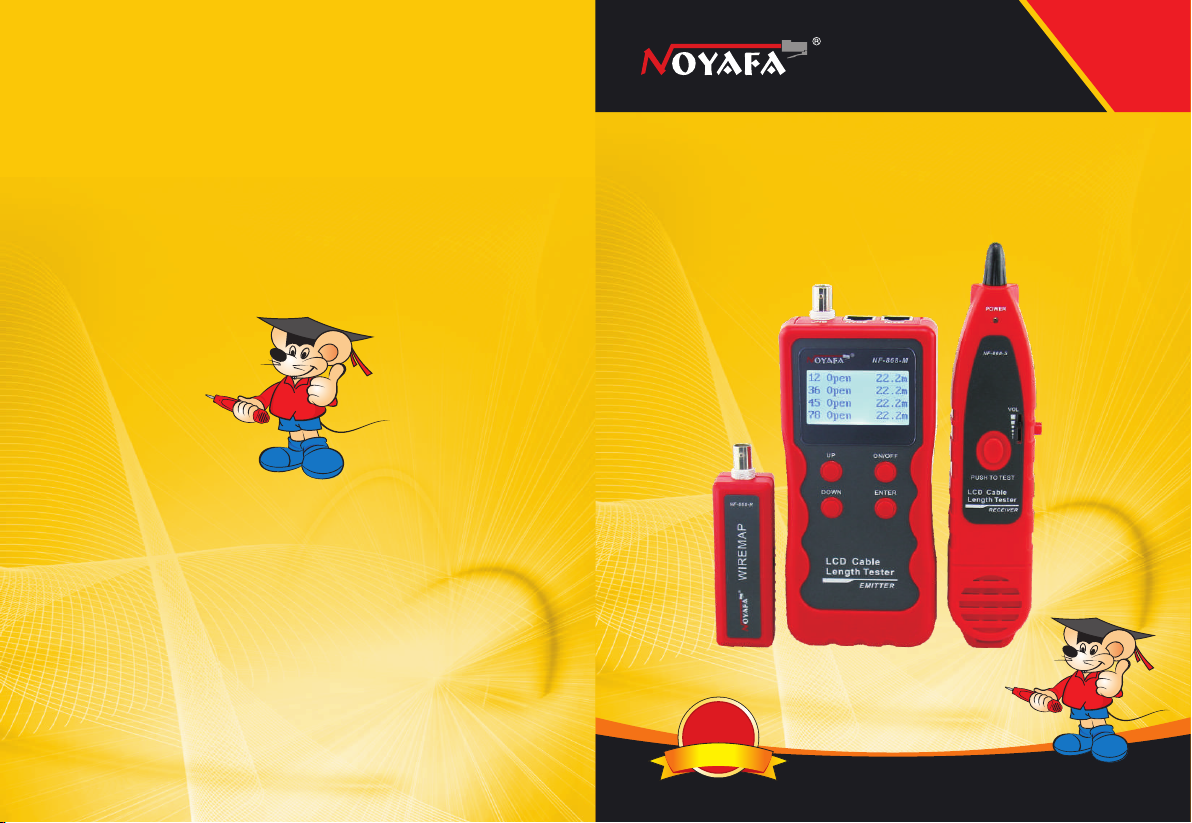
Your excellent helper in cable test!
Your excellent helper in cable test!
NF-868/NF - 8 6 8 A / N F -868W
INSTRUCTION MANUAL INSTRUCTION MANUAL INSTRUCTION MANUAL INSTRUCTION MANUAL
LCD Cable Length Tester
SHENZHEN NOYAFA ELECTRONIC CO.,LTD
n
u
o
C
ORI GINAL
ORI GINAL
AUT HENTI C
AUT HENTI C
d pr
e
t
n
e
t
a
P
ng
i
t
i
e
f
r
e
t
o
d
u
c
t
s
,
n
o
t
a
l
l
o
w
e
d
RE V1 .0
Page 2
Please read a nd learn sa fe ty instru ct ions
before us e or m aintain t he e quipmen t
● Ke ep th e te st e rs i n ri ght p la ce t o a vo id h urt w it h th e sha rp p rob e.
● Ne ver p ut t he e q ui pm ent i n th e pl a ce w it h muc h du st , h um id ity
an d hig h te mp e ra tu re (o ve r 40℃) .
● Pl eas e us e ba t te ry a cco rd in g t o th e sp eci fi ca tio n; o the rw is e, it
ma y res ul t in d a ma ge t o equ ip me n t.
● Pl eas e ne ver d is mo unt t he e qu i pm en t arb it ra r il y. Th e mai nt en
-a nce a nd c ar e s ha ll b e con du ct e d by p ro fes si on a l pe rs onn el .
● Th e tes te r wi l l sh ut o ff a uto ma tic al ly i f it do es n ot wo rk f or 1 5
mi nut es i n su c ce ss ion .
● Pl eas e ta ke o u t th e ba tte ry i n la u nc he r and r ec ei v er i f th e
eq uip me nt i s n ot u se d for a l on g ti m e so a s to p rev en t th at th e
ba tte ry l iq u id i s le ake d in f ut u re .
● Ne ver u se t he e q ui pm ent t o de te c t po we r cor d wi th e l ec tr ici ty
(s uch a s po we r s up pl y cir cu it o f 2 20 V) , oth er w is e, it m ay
re sul t in d am a ge t o eq uip me nt a n d pe rs ona l in ju r y.
●Ne ver c on du c t re la ted o pe ra t io n of c omm un ic a ti on l ine i n
th und er st o rm w ea the r so a s to p rev en t lig ht ni ng st ro ke an d
im pac t on p er s on al s afe ty.
CONTENTS
Ov erv iew.. ................. ... ... ... ... .......... .. ...01
Ma in function s ......... ........... ........... ... ... 02
Tec hnical Pa rameters... ... ........ ... ..... .... .02
Pr odu ct interfac e a nd key introdu cti on. .0 4
Pr odu ct operat ion metho d.. ....... .......... .05
a.C able l in e-to- line tes t.... ... ........ ... ....... .....05
b.C able len gth te st ........... ........... ...... ... .....09
c.C able trac ing tes t. ... ........ ... ...... .. ... .12
.. ..
.. ... .......
d.C rosstal k test. ........... ........... ........ ......... 15
Ch oos e th e La nguage ........ ... ........... ........16
Ca lib ration and s etup....... ........... ........... ..1 6
Da ta load ing........ ........... ... ........ ... ........... .18
Au to power-of f.. ........ ... ........ ... ........... ......18
Pa cki ng l ist........ ... ........ ... ........ ... ........... ..19
.. ..
.. ..
.. ..
.. .
.. ..
.. ..
.. ..
Your excellent helper in cable test!
Di agr am of series prod ucts ......... ........... ..2 0
Your excellent helper in cable test!
Page 3
Overview
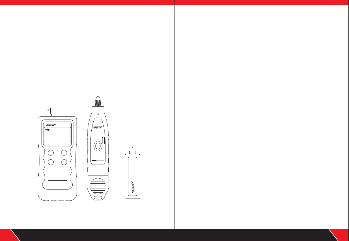
NF-86 8 Serie s are capab le
of av oidin g cur ren t i nte feren ce . The e quipm ent is com posed of thr ee
pa rts: ma in te st er (N F- 868-M ), rece iv er (N F- 868-S ) and rem ote
ide nt ifi er ( N F-8 68 -R) . I t has co up les of ci rc uit st a te tes ti ng
fu nctio ns i nc lu din g le ng th tes t, ca bl e li ne fin din g, l in e- to- li ne ,
cross talk and bre aki ng poin t, se rving as a practi cal t ool for lo w
v o l t a g e s ys te m i n s ta ll at ion a nd m ai nt e n a n c e t e c h ni ci ans
of commu nic ation ci rcu its and compr ehens ive wi ring circ uit s. I t is
widel y used in the f ields l ik e telep hon e sy ste m, c omput er netw orks
and oth er meta l lead ci rcu its.
newly d evelo ped by ou r com pany wh ich are
POWE R
NF-8 68-M
Lan g:Eng lish
Wir e ma pping
Ca ble Le ngt h
Sc an Cab le
UP
ON/OF F
ENTER
DOWN
LCD Ca ble
Len gth Tes ter
EMIT TER
Main te ster
(NF-8 68-M)
NF-8 68-S
VOL
PUSH TO TES T
LCD Cab le
Lengt h Teste r
RECEIV ER
Recei ver
(NF-8 68-S)
Remot e ident ifi er
NF-86 8-R
WIR EMAP
(NF-8 68-R)
Main f unctions
Ca pab le t o te s t op en , sho rt , c ro s s co nn ect io n, r eve rs e, pa ir in g
●
co nne ct io n a nd b ro ken w ir e po s it io nin g.
To pe rf orm c ro ss tal k te st on n et wo rk ca bl e to so lv e th e pot en tia l
●
pr obl em o f sl o w sp ee d.
To qu ic kly f in d th e tar ge t wir e or c ab le am on g kin ds o f wi res .
●
Me asu re l en g th o f ne two rk c ab l e, c oa xia l ca bl e ,t el eph on e ca b le
●
an d USB c ab le u p t o 20 00 m, no n ee d of r e mo te u nit .
To ma ke a a ccu ra te d ete rm ina ti on o f sho rt c irc ui t po sit io n .
●
To tr ac e cab le o n ex cha ng er or R ou te r wit ho ut cu rr en t int ef ere nc e.
●
Lo w vol ta ge pr om pt f unc ti on i s a va il abl e.
●
Re mot e un it w i th t on e whe n ch ec k in g wi rem ap
●
Fu nct io ns o f s to ra ge an d me mo r y.
●
Au tom at ic d e la y po wer o n- of f and b ac kl igh t fu nct io n.
●
Li ght in g lam p en ab les t o us e in a da rk e nv iro nm ent .
●
Si ngl e ch ip so ft wa re wa tc hd o g de si gn ru ns r el i ab ly.
●
Technical parameters
(1).
Overa ll dime nsi on s
Main te ster: 1 85X 80 X32 mm; Rec eiver : 218 X46X2 9mm
Remot e ident ifi er : 107 X30X2 4mm.
Displ ay
(2).
Dot mat rix 128 X64 ( Effec tiv e visib le area 5 6X40m m).
(3). Po wer sup ply
Main te ster: 9 V bat tery.
Recei ver: 9V b att er y.
(4).Testin g cable t ypes
STP/UT P 5E, 6 E netwo rk ca ble, te lepho ne cabl e, co axial c able,
USB cabl e and c om mon m etal wi res con nec te d wit h allig ator cl ip.
Your excellent helper in cable test!
01
Your excellent helper in cable test!
02
Page 4
(5).De tecti ng ca bl e typ es
STP/U TP 5E , 6E netw ork cab le, t eleph one cab le, coa xia l cable , USB
cable a nd comm on meta l wir es conn ected w ith a ll iga tor cli p.
(6).Op erati ng en vi ron ment te mpera tur e/hum idity
-10 ~ +60 /20% ~ 70 %;℃ ℃
(7).Testin g devic e inter fac e
Main un it: RJ4 5 (M) , RJ 45 (S ), loop i nterf ace , RJ 11, BN C con necto r,
USB B-t ype fem ale i nt erf ace;
Remot e ident ifi er : RJ4 5, RJ11, BNC co nnect or, USB A-t ype f emale
inter face.
(8).Le ngth me asu re men t
Range : 1-200 0m;
Calib ratio n preci sio n: 2% (+/ -0.5m , or +/ -1 .5 fe et); (c alibr ati on;
cable > 10m) me asu re men t preci sion: 3 % ((+ /- 0.5 m, or +/- 1.5 fee t);
(AMP, CAT5E, 6E c abl e mater ial)
Displ ay unit : met er, i nch , yard.
(9).Le ngth ca lib ra tio n, stor age and d ata l oad
User ca n set a len gth v al ue at a k nown le ngth, s tor e th e val ue in
the sys tem,w hic h ca n be us ed for fu ture ch oic e. a nd th e calib ratio n
lengt h shoul d be over 1 0m.
(10). Li ne sequ enc e an d cab le fail ure pos iti oning
Open, s hort, r eve rs e , cro ss, cro sstal k, et c.
(11).N F-868 W inc lu des 8 r emote u nits wi th ID 1-ID8 .
(12). Li ne trac ing f uncti on (Not e: NF-8 68A can’ t trace c abl e)
Locat e targe ted c ab le am ong lot s of cabl es
(13). La nguag e & Automa tic pow er- of f
Users c an choo se En gl ish o r Chine se for op erati on.
Users c an choo se ti me t o tur n off t he test er auto matic all y
(15mi ns, 30m ins ,4 5mi ns ,60m ins)
Product interface and key intro du ct io n
(M)
(S)
BNCSCAN
MAIN
POWER
NF-86 8-M
Lang :Engl ish
Wire map ping
Cab le Le ngth
RJ11
USB
Sca n Cab le
UP
ON/OFF
ENTER
DOWN
LCD Ca ble
Leng th Test er
EMITT ER
Main te ster (N F-8 68 -M)
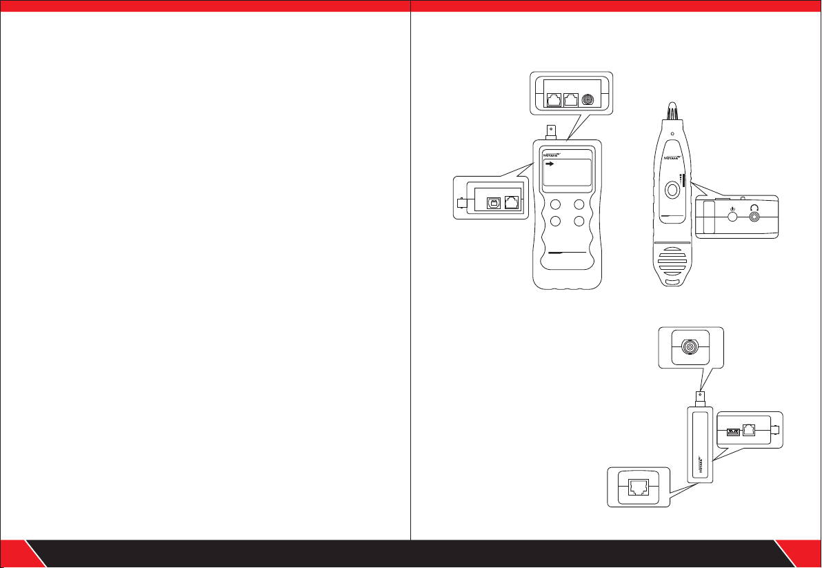
Main unit port instructions
(1). Two RJ 45 interfac es on the main unit:
one of them is “MAIN” interfac e (“M” for short),
and the other is “SCAN” inter face (“S” for shor t);
RJ11 interfac e, USB interfa ce
and BNC interface
(2). M interface is used for measur ing length and
others, but not for cable trac ing; “S” inter face is
used for cable tracing tes t and “local” conn ection test;
(3). RJ11 interf ace, USB inter face and BNC interface
on the main unit are used for
line-to-li ne, length tes ting and line
tracing.
NF-868 -S
VOL
PUSH TO TEST
LCD Cable
Length T ester
RECEIVER
Recei ver (NF -86 8- S)
BNC
RJ45
NF-868- R
RJ11
USB
WIREM AP
Your excellent helper in cable test!
03
Remot e ident ifi er ( NF- 868-R )
Your excellent helper in cable test!
04
Page 5
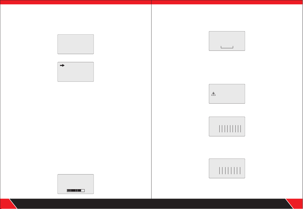
Product operation method
Boots cr een
Synch ron ous s elf tes t ( self te st dy nam icall y dis pla yed in the lin e
from le ft to r igh t)
5 secon ds late r, the fol low ing mai n inter face is d isp layed :
There are nine functional options in the main menu interface
(1) Language— English or Chinese.
(2).Wire mapping --- Connection and disconnection test: to test connection
of M, S R end-end cable and perform positioning of the failure.
(3).Cable Length---Pairing and length measurement: verify cable length,
open circuit distance and pairing, crosstalk.
(4).Scan cable---to find target cable among lots of network cables,
telephone cables, USB cables, coaxial cables and other kinds of wires.
(5).Type--- Pair / Tel / USB / COAX / BNC Cable.
(6).Unit---Meter / Feet / Yards.
(7).Calibrate— Seven calibration coefficient can be stored in it.
User can calibrate network/ telephone/ USB/ Coax cables.
(8) Data loading---Select the calibration coefficients stored in system.
(9) Auto power off— set the time for power off.
a.Cable line -to-line te st:
Taking network test as an example: aft er entering connect ion test function,
press “ENTER” key to check wir emap. At this time, the following int erface is
shown indicati ng test is in process:
------
to c h oo s e no yaf a
- -- - id en ti fy - -- -
we lcome
NF - 86 8
La ng: Engli sh
Wi re mappin g
Ca ble L en gt h
Sc an Ca bl e
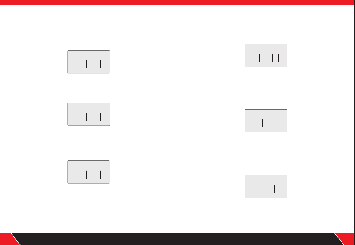
Test result 1 : Short circuit
If there is short circuit with the cab le and terminal, it will show as below:
(Short circuit wit h 3 and 6)
Sh o rt ma pp i ng :
1 2 3 4 5 6 7 8
At this time, press any key to return to the main menu , and then press
“ENTER” key for re-tes t.
Please do not perform test aga in until short circuit prob lem solved.
Test result 2: if the far end of the cable to be tested is not plugged in
remote adapter (R) or cable is not plugg ed into the local port (S),
the following interf ace is shown:
Ca b le op e n or
to o Sh or t !
Test result 3:correct connection
the following inte rface is shown:
Wir e Map: Remote
1 2 3 4 5 6 7 8 G
M:
R:
1 2 3 4 5 6 7 8 G
“M”stands for Master unit. “R” stands for remo te unit.
Test result 4: In case of open circuit existing on far end of the cable,
the following interface is shown:
Wir e Map: Remote
1 2 3 X X 6 7 8
M:
R:
1 2 3 X X 6 7 8
In the figure, “X” shown in “4” and “5” pin positi on, indicates there is
open circuit in “4” and “5” pin of the remote pin.
Your excellent helper in cable test!
05
Your excellent helper in cable test!
06
Page 6
Note: Because netw ork cable is made of pair cores, if there is open circu it,
it will show faults in pairs, just as above "4" &" 5". it means eit her "4" pin
or "5" pin exsits an open circuit , or bo th "4" and "5" exsit an open circuit.
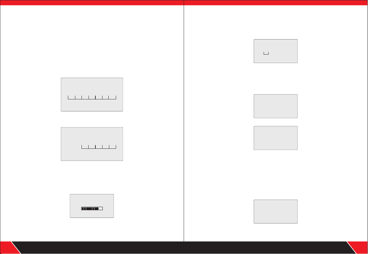
Test result 5: In case of open circuit existing at the near end of
the cable , the following interface
is shown:
In the figure, “X” shown in “3” and “6” pin positi on in “M” line, indicates there is
open circuit in “3” and “6” pin of the near pin.
Test result 6: In case of open circuit existing at the middle part
of the cable , the following interface
is shown:
In the figure, “X” shown in “3” pin positi on in “M” and “S” line, indicates there is
open circuit in “3” pin of the middle part of the cabl e. Perform"Cabl e Length"
to locate the exact fault point. Ref er to the related chapter below.
Test resu lt 7 : In case o f op en circ uit e xisti ng in the c able when
testi ng with main teste r and rem ote unit toge ther, the follo wing
inter face is s hown:
In the figu re, “X ” show n in “4” & “5” pin i n “M” & “R” lin e, It has t wo pos sib le resul ts.
Both “4” an d “5” pin ar e open cu rcuit ed. Or , eit her “4 ” or “5” pin is open.
Note: Wh en che cki ng wirem ap wit h main te ster and remot e unit to get her,
the cabl e is test ed in pai r. Thus , if ther e is one pin is open , it wil l show in pa ir
as above.
To t est wh ich pi n is open, use rs can ch eck wi remap on ly wit h main te ste r like
Examp le 4,E xam ple 5 an d Exam ple 6 do .
when testing only with main tester
Wir e Map : Loc a l
1 2 X 4 5 X 7 8
M:
S:
1 2 3 4 5 6 7 8
when testing only with main tester
Wir e Map : Loc a l
1 2 X 4 5 6 7 8
M:
S:
1 2 X 4 5 6 7 8
Wir e Map :Re mot e
1 2 3 X X 6 7 8
M:
R:
1 2 3 X X 6 7 8
Test result8: USB cable line sequence test
Before checking wiremap of USB cable, users need to choo se "USB (4)"
in "Type" . and then return t o main menu to chec k its wire map. If t he
testing cable is in good conne ction, Th e following interfa ce will be shown:
At this time, press any key to return to the main menu , and then press“ENTER”
key for re-test.
Test result 9: 6-core telephone cable line sequence test
efore checking wir emap of telephone cable , users need to choose "TEL(6)"
in . and then return to main menu to chec k its wiremap. If the
testing cable is in good conne ction, it will display s as fo llows:
At this time, press any key to return to the main menu , and then press
“ENTER” key for re-test.
Test result 10: BNC coaxial cable line sequence test
Before checkin g wiremap of BNC cable, users need to choos e "BNC(2)"
in . and then retur n to main menu to check its wi remap. If the
testing cable is in good conne ction, it will display s as fo llows:
At this time, press any key to return to the main menu , and then press
“ENTER” key for re-tes t.
"Type"
"Type"
Wir e Map: Remote
1 2 3 4
M:
R:
1 2 3 4
Wir e Map: Remote
1 2 3 4 5 6
M:
R:
1 2 3 4 5 6
Wir e Map: Remote
1 2
M:
R:
1 2
Your excellent helper in cable test!
07
Your excellent helper in cable test!
08
Page 7
Remote unit with tone when checking wiremap
When use rem ote un it to check wiremap, users can distingus h the test result firstly via
tones. When the cable is normal , the remote unit will generate “ beep ” long and slowly.
When the cab le is abnorma l, the the remote unit will generate “ beep ” sh ort an d quic kly.
Special use:
In case of exchanger power-on, the main unit
can test line sequence of the connecting cables
Take network cable as an examp le: one end of the cable is connected with
“MAIN” interfa ce of the main unit, and other end is connecte d with exchanger
interface. And direc t connection test can be perfor med. If the exchanger inter face
tested is reliably con nected, the followi ng interfaces shown (ex changer interfa ce
is 8-core):
Shor t ma pping:
1 2 3 4 5 6 7 8
In case of open circuit with line 1 and 2 of the exchange r tested, the following
interface is shown (ex changer interfa ce is 8-core):
Shor t ma pping:
1 2 3 4 5 6 7 8
b.Cable leng th test:(Test len gth only with t he m ain tester,
don’t conne ct cable into remote uni t.)
Firstly insert one end of the testin g cable into “M” port in the main tester. When
entering ”Pair &Length” testing functio n to ch eck the length.
At this time, the followin g interface is shown:
- -- - id en ti fy - -- -
Note: Due to d ifferent technica l par ameters wit h different branded cables,
users are recommen ded to use dynamic calibrat ion function of the equipme nt
before measuri ng length (Refer to the related cha pter for more details.) .
Test result 1 : Short circuit
If there is short circuit with the cab le and terminal, the follow ing interface is
shown (Short circu it with 2 and 3)
Sh o rt ma pp i ng :
1 2 3 4 5 6 7 8
At this time, press any key to return to the main menu , and then press
“ENTER” key to other funct ions.
Please do not perform test aga in until short circuit prob lem solved.
Test result 2: In case of normal pairing and length test,
the following interface is shown:
1 O pe n 105 .0m
2 O pe n 105 .0m
3 O pe n 105 .0m
4 O pe n 105 .0m
And then press “UP” or “DOWN” key, the following inter face will further be shown:
5 O pe n 105 .0m
6 O pe n 105 .0m
7 O pe n 105 .0m
9 O pe n 105 .0m
Thus , the cable is almost 105m . Only one end of cable connec t with main
tester, the other end needs no connect ion, so it show "Open" in the picture
At this time,press “EN TER” to return to the main menu,an d then press
“ENTER” key for re-test. .
Test result 3 : USB cable len gth test
Insert on e end of the USB cable to be tested int o “USB” port o f the
main tes ter, the other end ne eds no connetion, select “USB(4)” Type, return to
the main menu, and select leng th test, and then press “ENTER” key to perf orm
length test with the equip ment, the following int erface will be shown:
1 O pe n 10. 1m
2 O pe n 10. 1m
3 O pe n 10. 1m
4 O pe n 10. 1m
It indicates that leng th of USB cable is 10.1m. At this time, press any key to
return to the main menu, and then pres s “ENTER” key for other testing .
Your excellent helper in cable test!
09
Your excellent helper in cable test!
10
Page 8
Test result 4 : RJ11(TEL) ca ble length te st
nsert one end of the RJ11 cab le to be te sted into “RJ11” port of the main
I
tester, the other end needs no conne ction. select “Tel(6)” mode , return to the
main menu, and select leng th test, and then press “ENTER” key to perf orm
length test with the equip ment, the following int erface will be shown:
1 O pe n 1 0 .1m
2 O pe n 1 0 0 . m
3 O pe n 1 10 . m
4 O pe n 1 10 . m
And then press “UP” or “DOWN” key, the following inter face will further be shown:
5 O pe n 1 0. 1m
6 O pe n 1 0 .1m
It indicates that leng th of telephone cable is 10.1m
with main tester, the other end needs no conne ction, so it show "Open" in the
pictureAt this tim e,press “ENTER” to retu rn to the main menu,and then press
“ENTER” key for re-test. .
.
Only one end of cable connect
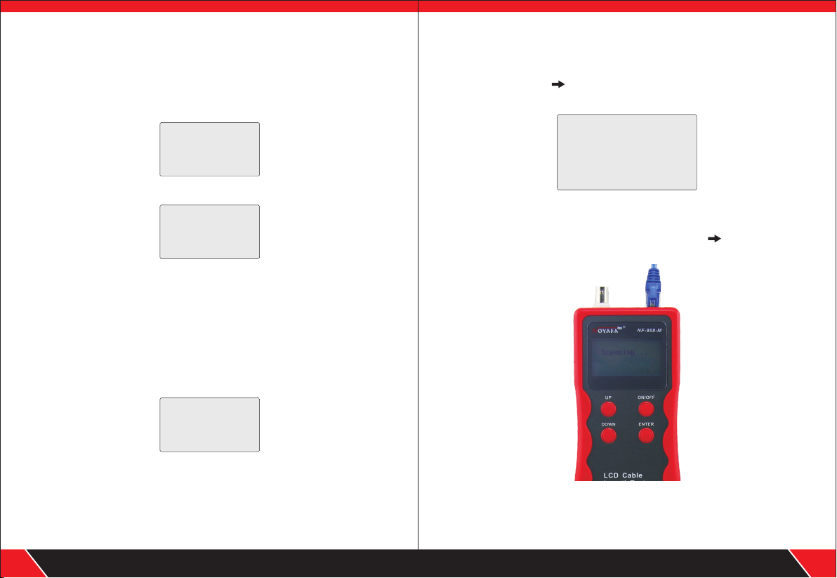
c. Cable tracing test:
After powering on the main tes ter and entering main test menu , press “UP”,
“DOWN” key to move “ ” cursor to cable scan, and then pre ss“ENTER”
key to find the line. Th e following interfa ce will be shown:
Connect the cable to be found with the cor responding RJ45 (Scan) port
emitter
, (RJ11,USB or BNC) . Take netwo rk line finding as an example:
connect the networ k cable to be found with Rj45 port, move “ ” cursor to
cable scan, and press “ENT ER” key to perform line finding tes t as sh own in
the figure below:
Test result 5 : BNC cable len gth test
If to insert one end of the BNC cable to be tested into “BNC” por t of th e main
tester, the other end is an open circuit , select “BNC(2)” mode, ret urn to the
main menu, and select leng th test, and then press “ENTER” key to perf orm
length test with the equip ment, the following int erface will be shown:
1 O pe n 1 0. 1m
2 O pe n 1 0 .1m
Sc anning. . .
of the
It indicates that leng th of BNC cable is 10.1m. At this time, press any key to
return to the main menu, and then pres s “ENTER” key for re-test.
Your excellent helper in cable test!
11
Your excellent helper in cable test!
12
Page 9
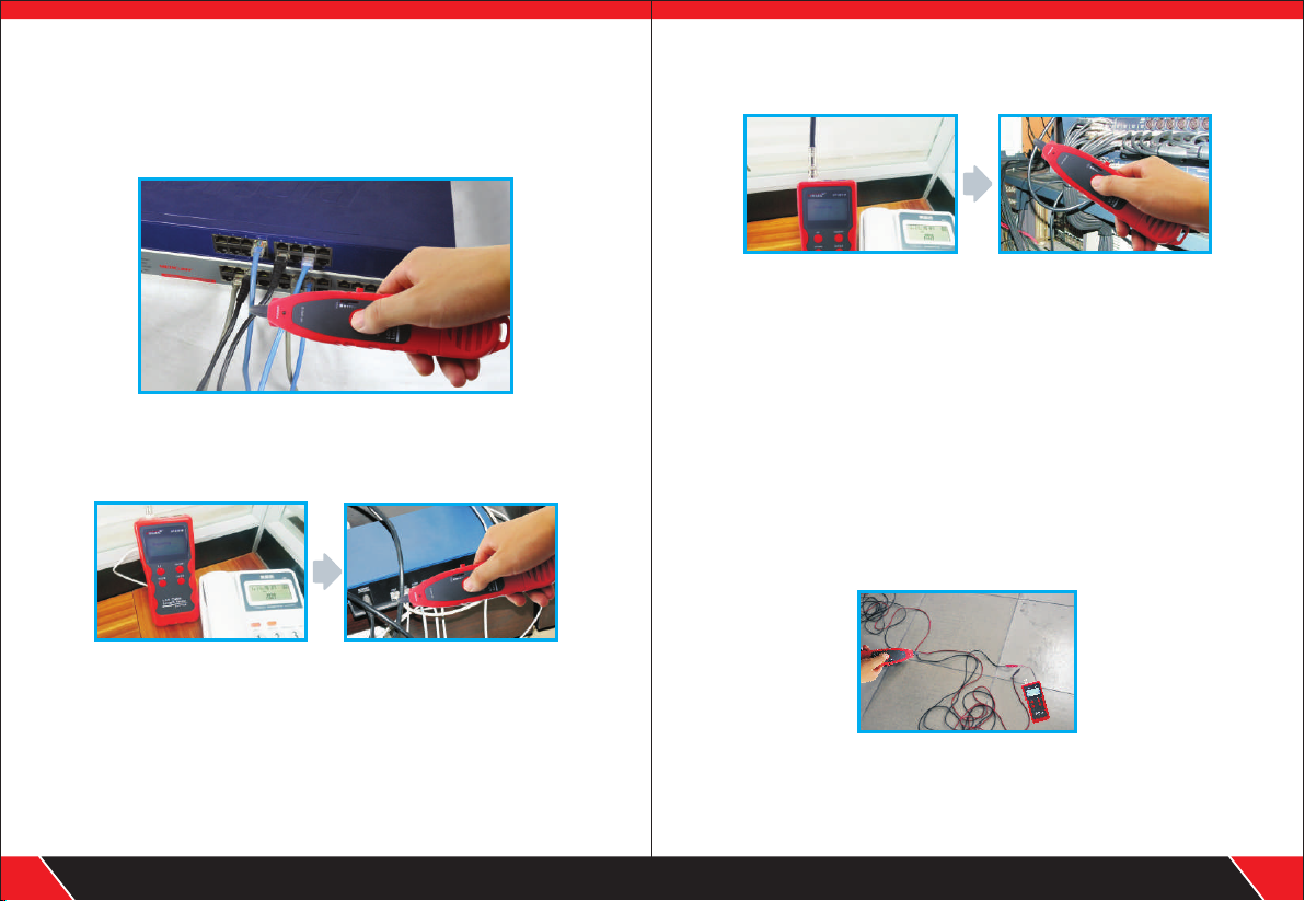
The usage of receiver
Insta ll 9V b att ery, push t he test k ey, ge t clo se to t he ca bles wi th pr obe .you ca n
hear “b eep ”, th e power l ed fl ash es. When the p rob e fin ds the ta rge ted c able, the
voice w ill b e lou dest, a nd th e led l ight will be b rig hte st.
1.Trac ing cable (RJ 45/RJ11 Cabl e) which is conne cted to
switch or router.
Insert the cable into port RJ11/ RJ45 (S), Press the testing key of receive r, “P ower”
will be lighted, then hold the recei ver close to the cables, when the probe get s close
to the targeted one, you can hear clea r and loud “beep,beep, beep ” .
(Note: telephone cab le into RJ11, Lan cable into por t RJ45(S) )
2.Trac ing Coax cabl e
Insert the cable into port BNC , Press the testing key of receiver, “Pow er” will be
lighted, then hold the rec eiver close to the cables, when the pro be gets close to the
targeted one, you can hear cle ar and loud “beep,beep, bee p” .
(Note: turning dow n the voice slowly help trace cable eas iler. )
3.Locate th e short or breakge p oi nt (eg: metal l ine)
Connect the metal line wit h the cable clips, press the testin g key of re ceiver, hold
the receiver close to the cabl es, “beep, beep,bee p” will generate, but when the
probe targets the brea kge point, “beep,be ep,beep” stops, whi ch indicates that
is where the breakage is.
Note: 1) the metal line is de-ene rgized.
2) Tur n up th e voice, which helps locate bre akge easily.
3) Two cables must be connec ted together, if only one cable, the bla ck clip
has to be gr ounded.
Your excellent helper in cable test!
13
Your excellent helper in cable test!
14
Page 10
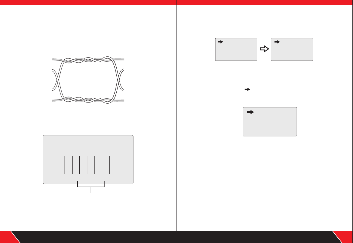
d. Crosstalk test
As shown the figure belo w: it shows 3, 6 an d 4, 5 with crosstalk. T he line
pair with cros stalk will flas h to indicate fai lure. In the line p air with crosstalk,
end-to-end conn ection is correct . Howe ver the connecte d line s are from
diffe rent line pairs. Line pair crosstalk will caus e an over large crosstal k,
otherwise ne twork speed wil l be slow.
3
6
4
5
Connecti on di agr am of c ros sta lk li ne pa ir
3
6
4
5
Crosstalk interface is shown as below:
Choose the La nguage, Chi nese or Eng lish
then you can get the screen as you desired .
Lan g: Englis h
Wir e Mapping
Cab le Length
Sca n Cable
语 言: 中 文
对 线 测 试
长 度 测 试
寻 线 测 试
Calibration and setup
After powering the mai n tester and entering the main test men u, press “UP”,
“DOWN” key to move cursor “ ” to “Configu re” , and then press “ENTER”
key to perform calibrati on and setup function. The following
interface will be show n:
Type: PA IR (8 )
U n i t: Meter
C a libration
L o a d D a ta
Wire Map: Remote
1 2 3 4 5 6 7 8
M:
R:
1 2 3 4 5 6 7 8
Cro sst alk line pair flashes
Note: In case o f the non -tw is ted -pair c able li ke te le pho ne cabl e,
due to ov er larg e cro ss tal k, it gen erall y sho wn a s cro sstal k.
Your excellent helper in cable test!
15
Type selection:
1). Type: twisted-pair cable
When testing netwo rk cable, users need to firstly cho ose”Pair(8) ” in”Type”
after this, users can test cab le length and check its wiremap .
2). Type: telephone cable
When testing telep hone cable, users need to first ly choose”Tel(6)” in”Type ”
after this, users can test cab le length and check its wiremap .
Your excellent helper in cable test!
16
Page 11
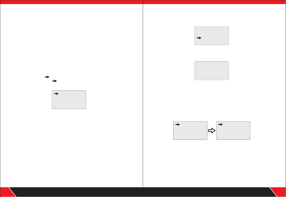
3).Type: USB cable
When testing USB cable , users need to firstly choose” USB(4)” in”Type”
after this, users can test cab le length and check its wiremap .
4). Type: BNC coaxial cable
When testing BNC cable , users need to firstly choose” BNC(2)” in”Type”
after this, users can test cab le length and check its wiremap .
Unit setup:
Set unit: meter
When moving cursor to “Unit” item, press “ENT ER” key till unit of meter
is shown. Move the cursor “ ” to “Return” ite m, press “ENTER” key to return
to the main menu. Th e following interfa ce will be shown:
Note: Setup of the unit of inch and yard is just the same as that of meter.
“ ”
Type : PAI R(8)
U ni t: M ete r
C al ib ra ti on
L o a d D a t a
Calibration function:
Due to differen t materials of the cables, cal ibration is required before
testing the cables . The functio n of ca libration is for accurately measu ring
length of the cables.
When starting dyna mic calibration , insert the same type of cables at a
specified leng th into “M” port. It is unnecessary to inse rt into remote unit.
C a l i b r a t i o n ?
No Y es
Select “Yes ”, and then press “ENTER” key, the measured length will be show n:
At this time, press “UP” or “DOWN” key to adju st to show the actual length
as below:
- - Bas e Ad jus t- - -
12.5m
When length is given, press “ENTER” key to save the calibration value. The screen
will show calibration 1, cabliration 2...calibration 7. Users can choose it from
“Data load”, which can avoid more calibration next time.
Data loading:
Choose the functions of “Load data”, it will show 7 sets of length values which
were stored before. Select the desired one and then start to test the cable length.
C al ib ra te 1
C al ib ra te 2
C al ib ra te 3
C al ib ra te 4
C al ib ra te 5
C al ib ra te 6
C al ib ra te 7
Re tu r n
Auto power-off :
Choose the time for power off according to your own requirement.
Your excellent helper in cable test!
17
Your excellent helper in cable test!
18
Page 12
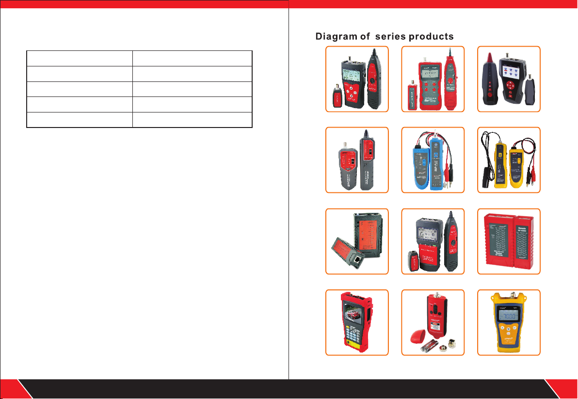
Packing list
1. Emit ter 1 PCS
2. Rece ive r 1PC S
3. Remo te ad apt er 1PCS
4. Earp hon e 1P CS
5. RJ11 Adapto r cab le 1P CS
Note:
(1). NF- 868A can ’t trac e cable .
(2). NF- 868W in clu des 8 rem ote uni ts with I D1- ID8.
6. RJ 45 Adapt or ca ble 1PCS
7. Allig ato r cli p adapt or 1P CS
8. User m anu al 1PCS
9. Kit 1PC S
10. Col or bo x 1PCS
NF-300 NF-838 NF -8601
NF-268
NF-806B NF-816
NF-468L NF-8200 NF-HDMI
Your excellent helper in cable test!
19
NF-701 NF-905 NF-906A
Your excellent helper in cable test!
20
 Loading...