

Page 1

GYROSET HEAD DRIVE
USER MANUAL
Document identifier: NOW.Q.CE.M.EN-GS-0002-01
Revision: 01
Date of issue: 30 November 2019
©2019 Now Technologies Ltd. All rights reserved.
Now Technologies, the Now Technologies logo, and the GyroSet And Glory names are
trademarks of Now Technologies Ltd., registered in 18. Reáltanoda street, Budapest,
1053 Hungary.
European representative of the Manufacturer:
Now Technologies Ltd., 18. Reáltanoda street, Budapest, 1053 Hungary
www.nowtech.hu
Page 2

Table of Contents
Table of Contents 2
User Guide 4
SYSTEM REQUIREMENTS 5
Safety and Handling Instructions 6
BATTERIES 6
MEDICAL DEVICE INTERFERENCE 6
SPECIAL SAFETY WARNING 7
Getting Started 8
What’s in the box 8
GyroSet Vigo 10
GyroSet Cubo 11
GyroSet LINK 11
Glory Tools Application 12
Assembly instructions 13
System connection diagram 13
GyroSet Vigo assembly 13
GyroSet Link installation 13
GyroSet Link Mounting 14
GyroSet Link Wiring to PGDT 15
GyroSet Cubo Mounting 17
Connecting the GyroSet Cubo to the Link and to the Headrest Sensor 18
Headrest and Headrest Sensor 19
Jack connector on Cubo 19
How to place the Headrest Sensor on the wheelchair? 19
Setting up the System 21
Setting up the Omni and the GyroSet Link 21
Programming the Omni 21
Setting up the IOM and the GyroSet Link 23
Setting up the Dynamic Controls Linx DLX-IN500 and the GyroSet Link 23
Setting up the Quantum Rehab Q-Logic 3 EX Enhanced Display and the GyroSet Link 23
Setting up the Vigo 23
Pairing to your phone (optional: to receive calls and listen to auditory type
entertainment) 23
GYROSET LINK CONFIGURATION 24
Personalize the driving experience 24
Page 3

Setting the driving parameters in the OMNI for safe and twitch-free acceleration 24
How to wear and drive with the GyrsoSet Vigo? 27
How to wear the Vigo? 27
Turn on the System (for assistants/carers) 28
Driving with the GyroSet Vigo 28
Switch modes with the Vigo 28
Drive with your Vigo 29
Using the OMNI Menu 30
Other GyroSet Vigo Functions: 30
Answer and incoming call 30
End a call 30
Reject a call 30
Adjust the volume 30
Play/Pause 30
Power off 31
Battery charging & battery level 31
Music streaming 31
Sleep mode 31
GyroSet Vigo Product Specifications 31
Appendix 32
GyroSet Vigo LED Indications: 32
GyroSet Link LED (GyroSet Logo) Indications: 32
GyroSet Link Audible feedback: 33
GyroSet Cubo system status feedback 34
SPECIAL SAFETY CHECKLIST 35
WARRANTY 36
Revision History 37
Page 4

User Guide
R-Net OmniⓇ and the R-Net logo is the property and registered trademark of PG Drives
Technology. Now Technologies Ltd. is not associated with PG Drives Technology.
Quantum Q-Logic is the property and registered trademark of Quantum Rehab. Now
Technologies Ltd. is not associated with Quantum Rehab.
Linx is the property and registered trademark of Dynamic Controls. Now Technologies
Ltd. is not associated with Dynamic Controls.
Please review this user manual before using the GyroSet Vigo with
GyroSet Cubo.
Information contained in this publication regarding device applications and the like is provided
only for your convenience and may be superseded by updates. It is your responsibility to ensure
that your application meets with your specifications. NOW TECHNOLOGIES MAKES NO
REPRESENTATIONS OR WARRANTIES OF ANY KIND WHETHER EXPRESS OR IMPLIED,
WRITTEN OR ORAL, STATUTORY OR OTHERWISE, RELATED TO THE INFORMATION,
INCLUDING BUT NOT LIMITED TO ITS CONDITION, QUALITY, PERFORMANCE,
MERCHANTABILITY OR FITNESS FOR PURPOSE. Now Technologies disclaims all liability
arising from this information and its use. Use of Now Technologies devices in life support and/or
safety applications is entirely at the buyer’s risk, and the buyer agrees to defend, indemnify and
hold harmless Now Technologies from any and all damages, claims, suits, or expenses resulting
from such use. No licenses are conveyed, implicitly or otherwise, under any Now Technologies
intellectual property rights.
The Now Technologies and GyroSet logo are registered trademarks of Now Technologies Ltd.
It is our intention to provide our valued customers with the best documentation possible to
ensure the successful use of your Now Technologies products. To this end, we will continue to
improve our publications to better suit your needs. Our publications will be refined and
enhanced as new volumes and updates are introduced. If you have any questions or comments
regarding this publication, please contact our Helpdesk via email at [email protected]. We
welcome your feedback.
Page 5

SYSTEM REQUIREMENTS
A wheelchair equipped with:
● PGDT R-Net:
○ Omni or
○ Omni2 or
○ IOM Input/Output Module, or
● Dynamic Controls:
○ Linx DLX-IN500, or,
● Quantum Rehab:
○ Q-Logic 3 EX Enhanced Display or SCIM Module
Requirements for the Glory Tools software that enables the personalization of the driving
experience:
● Either a Mac computer with High Sierra or later (Please note that the system will most
probably function with Sierra as well, but you need to enable virtual keyboard size
change in the System Preferences of the operating system)
● Or a personal computer with a Windows 8 or later operating system
Page 6

Safety and Handling Instructions
BATTERIES
Don’t attempt to replace any of the GyroSet System’s batteries yourself – you may damage the
battery, which could cause overheating, fire, and injury. The lithium-polymer battery in your
GyroSet Vigo should be serviced or recycled by Now Technologies Ltd. or an authorized service
provider and must be recycled or disposed of separately from household waste. Dispose of the
batteries according to your local environmental laws and guidelines.
THE GYROSET VIGO USES A LITHIUM-POLYMER BATTERY
Keep it away from anything that can catch fire and make sure it cannot get hit by sharp objects.
For charging, only use the charging cord provided.
Avoid storing and using the GyroSet Vigo below -10 and above 50 degrees Celsius. Do not
place the GyroSet Vigo in direct sunlight or keep it in hot vehicles.
Stop using the GyroSet Vigo if you notice these problems: odor, change in color, too much heat,
change in shape, leaking, odd noises. If it is safe to do so, move the device away from anything
that can catch fire.
MEDICAL DEVICE INTERFERENCE
GyroSet Link, GyroSet Vigo and the GyroSet Cubo contains components and radios that emit
electromagnetic radiation. This electromagnetic radiation – although unlikely - may interfere with
pacemakers, defibrillators, or other medical devices. Maintain a safe distance of separation
between your medical device and the above mentioned GyroSet devices. Consult your
physician and medical device manufacturer for information specific to your medical device. If
you suspect any of your GyroSet devices is interfering with your pacemaker, defibrillator, or any
other medical device, stop using the GyroSet system.
Page 7

SPECIAL SAFETY WARNING
When driving with the GyroSet Drive system, do not forget to switch modes in order to be
able to safely look around or control the actuator(s).
When driving with the GyroSet Drive system, make sure that the user is properly trained
by a trained professional and have enough (a couple of weeks minimum) indoor
experience driving the wheelchair before starting to drive outdoors in traffic.
Always make sure that the blink detection sensor is in a safe distance from your eye,
cheek or the corner of your mouth – 1-3 cm – and in a position that a sudden change in
the position of the GyroSet Vigo won’t hurt your eye.
Circumstances that can affect the operation of the GyroSet Vigo:
The GyroSet head drive offers unprecedented freedom of movement by using wireless radio
communication. The operation can be disturbed in environments with above-average Bluetooth
or Wifi device usage, this may result in a safety stop.
Please refer to our special safety checklist at the end of this document!
Page 8
Getting Started
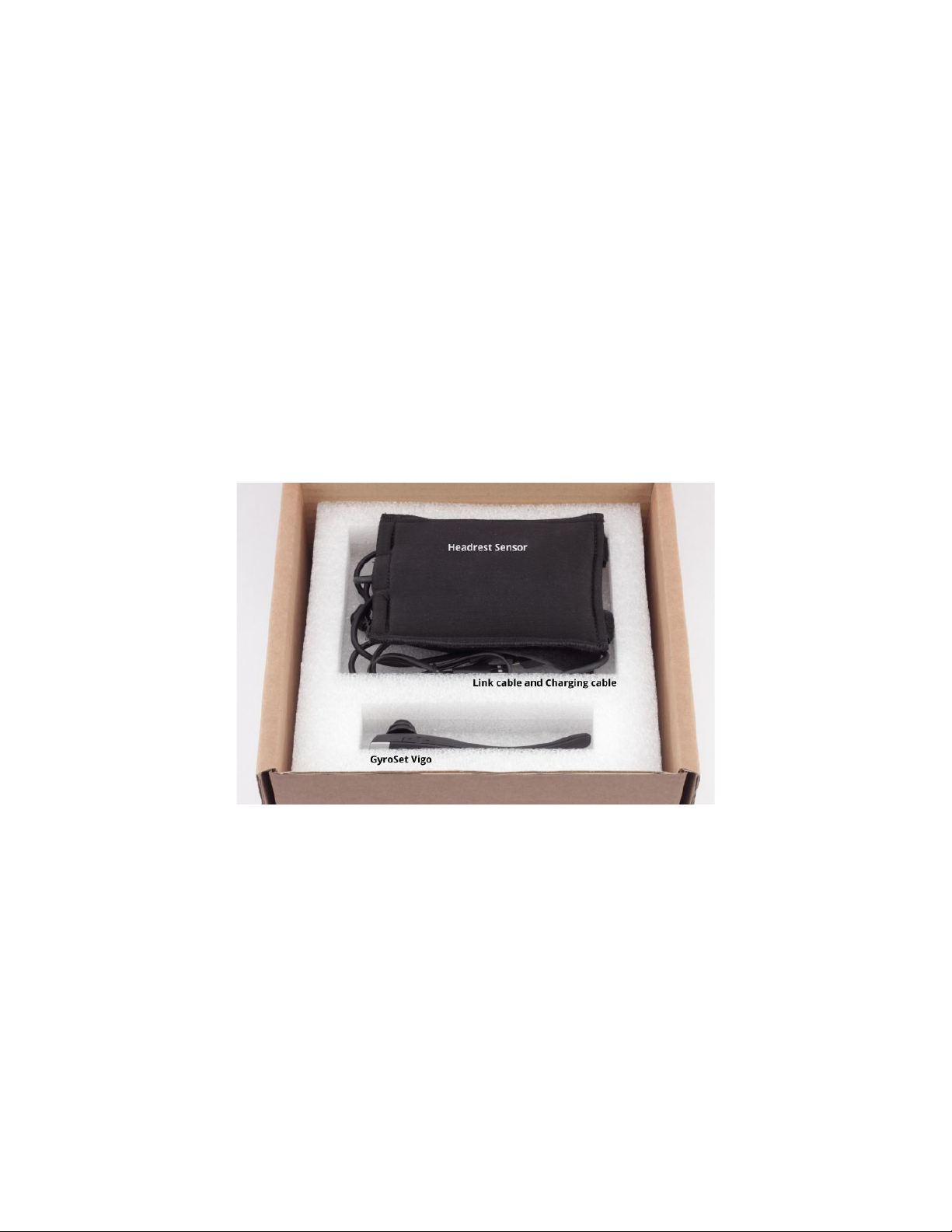
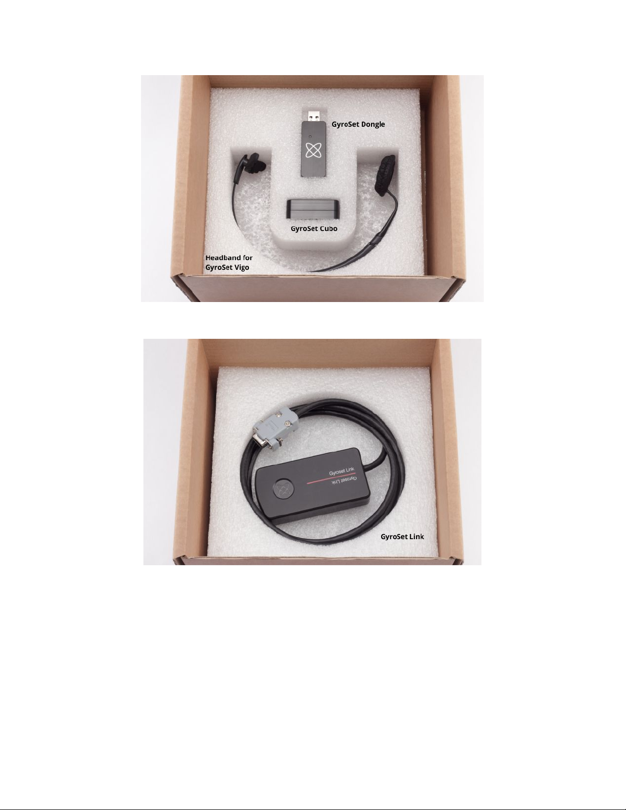
What’s in the box
- GyroSet Link
- USB to micro-USB cable to charge the GyroSet Vigo
- GyroSet Dongle
- GyroSet Vigo with plastic “C” mounting ring
- The headband of GyroSet Vigo
- Special Micro-USB to Micro-USB cable to connect the GyroSet Link and the GyroSet
Cubo
- GyroSet Cubo
- Headrest Sensor
Page 9
Page 10
GyroSet Vigo
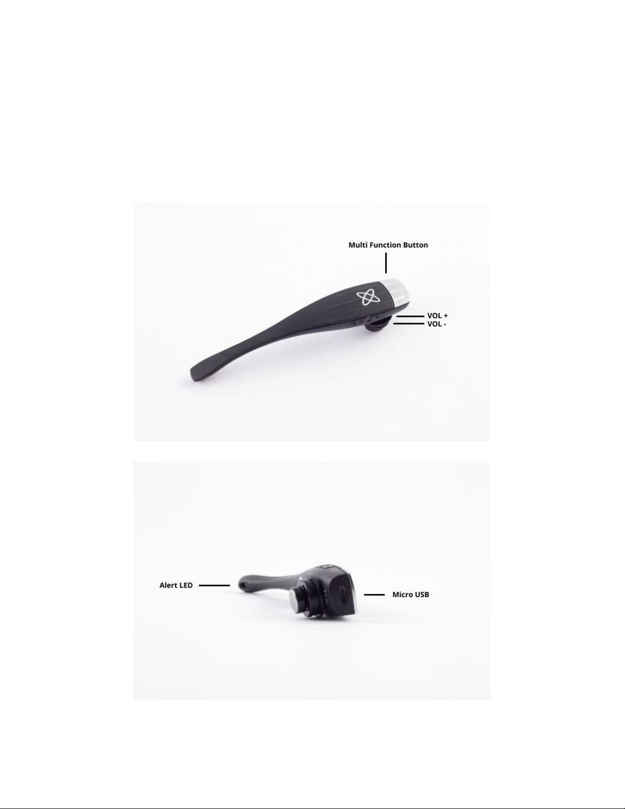
What does the Vigo do?
The GyroSet Vigo is a headset that measures the head movements of the user in three
dimensions and transfers signals to the GyroSet Cubo via bluetooth to enable driving.
It also supports other functions such as receiving phone calls and listening to music (not
recommended while driving).
Page 11
GyroSet Cubo
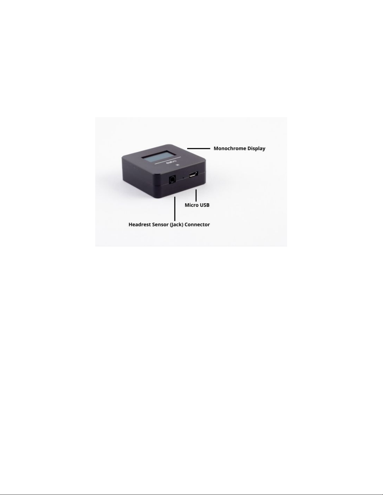
What does the Cubo do?
The Cubo provides visual feedback to the end-user via its display. It also receives the signals
from the GyroSet Vigo, calculates the orientation of the user’s head and transfers commands to
the GyroSet Link.
GyroSet LINK
What does the LINK do?
The GyroSet Link translates the user’s head movements into analog joystick signals that are
interpreted by the wheelchair’s controller system.
Page 12
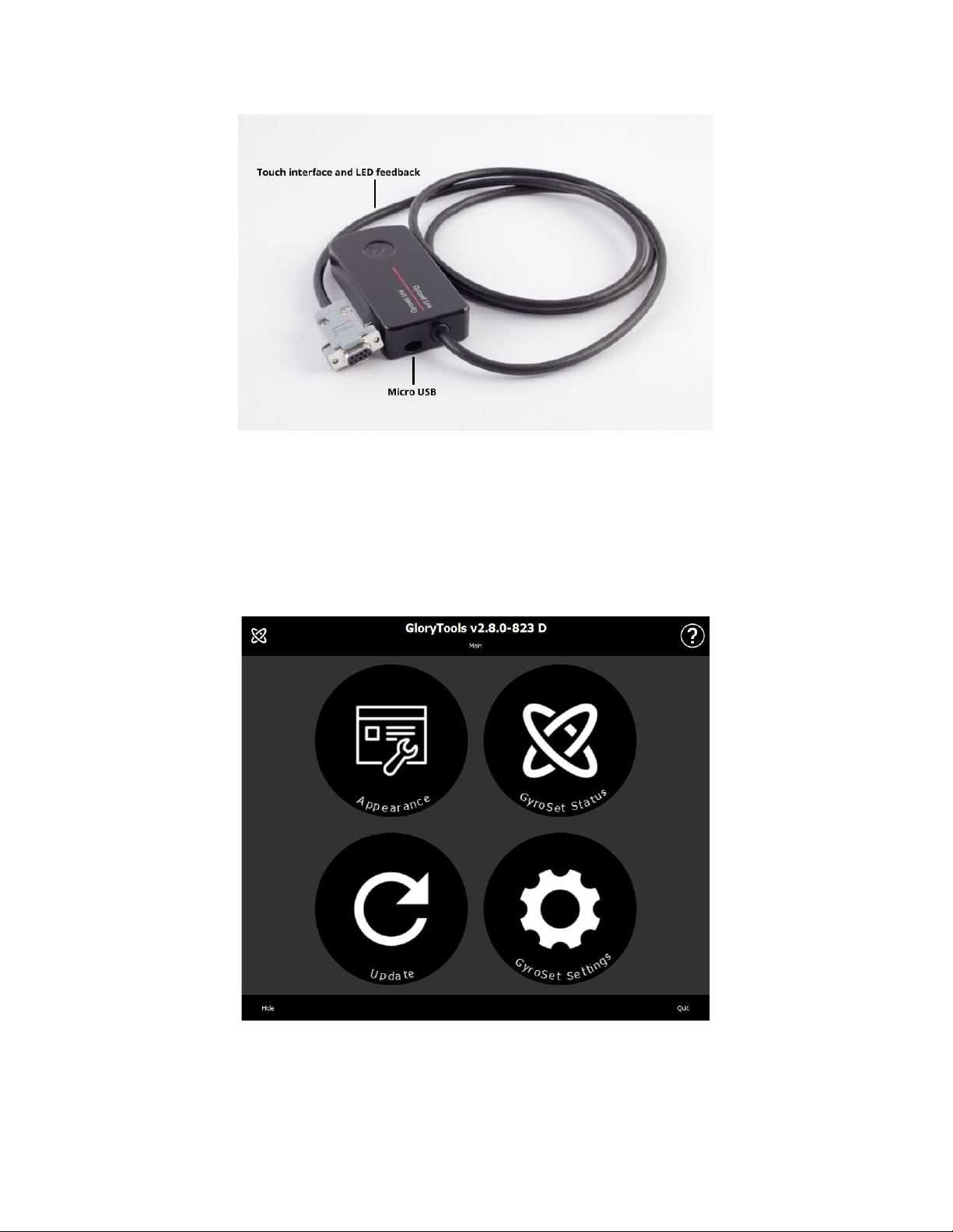
Glory Tools Application
The Glory Tools Application (GT) is a desktop software application that allows the user to set
up, customize, adjust and calibrate the various components of the GyroSet product family,
namely the head drive. It is available to download from:
https://nowtech.hu/downloads
Page 13
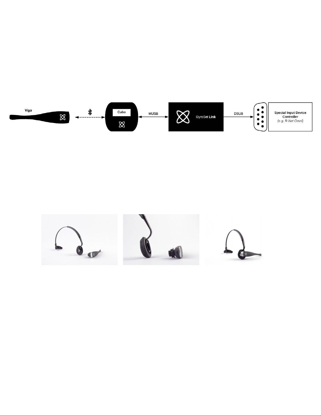
Assembly instructions
System connection diagram
GyroSet Vigo assembly
GyroSet Link installation
GyroSet Link enables GyroSet Vigo users to use their GyroSet Vigo on a PGDT Omni or IOM or
Quantum Q-Logic 3 EX Enhanced Display or SCIM Module or Dynamic Linx DLX-IN500
equipped wheelchair as a specialty input device (SID). The Omni is a universal specialty
controls interface that accepts signals from many different types of SIDs and translates them
into commands compatible with the PG Drives Technology R-Net control system.
Before proceeding please make sure that one of the compatible devices are already installed on
the chair and working properly. For more information on how to set up the Omni please follow
the instructions of R-Net OMNI TECHNICAL MANUAL SK78813/7. It is possible to set up a
Page 14
control system so that it is unsuitable for some users or even some vehicles. Although this guide
contains recommended settings for Omni for all of the above reasons it is important that you
contact PG Drives Technology if you have the slightest doubt or if you need any advice on
programming the product.
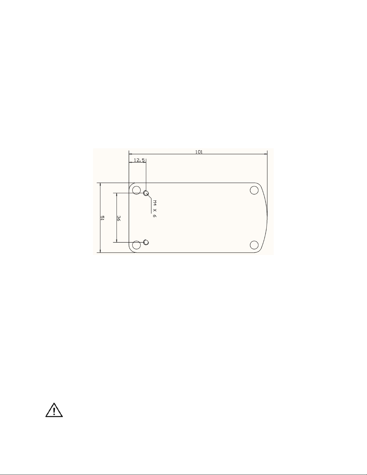
GyroSet Link Mounting
The GyroSet Link enclosure has two M4 nuts at the back of the device that is designed
specifically for mounting. As every vehicle and user is unique there is no general mounting
bracket available.
Please make sure that the physical mounting meets the following criteria:
❏ To take advantage of the IP54 protection of the casing, cables must face the ground to
prevent rain getting into the connector:
❏ GyroSet Link’s mode selection touch interface (touch button with the logo) must be
accessible for the caretaker.
• Devices that may produce high capacity charges, such as ionisators must be at a safe
distance from the touch interface to avoid accidental activation.
❏ The audible feedback of the GyroSet Link is of high importance for the user, placement
should avoid blocking of the speaker.
WARNING Protection against water according to IP54 is guaranteed only in case the
Link has been installed in a vertical position.
Page 15
GyroSet Link Wiring to PGDT
The GyroSet Link provides a proportional analog signal compatible with the PGDT Omni (and
some other controller systems – see in System Requirements). The interface is a standard
D-type connector, fitted with “detect link” and “fifth switch” functions. As there is no internal
power source or auxiliary power input connector on the GyroSet Link the power for operation is
provided by the Omni.
If the Omni is configured with the programmable parameter “Sleep 12V” to cut the power on SID
connectors when turned off, GyroSet Link is going to be turned off as well. GyroSet Link doesn’t
require a permanent power supply. For power saving reasons “Sleep 12V” parameter is advised
to be set in the R-Net system.
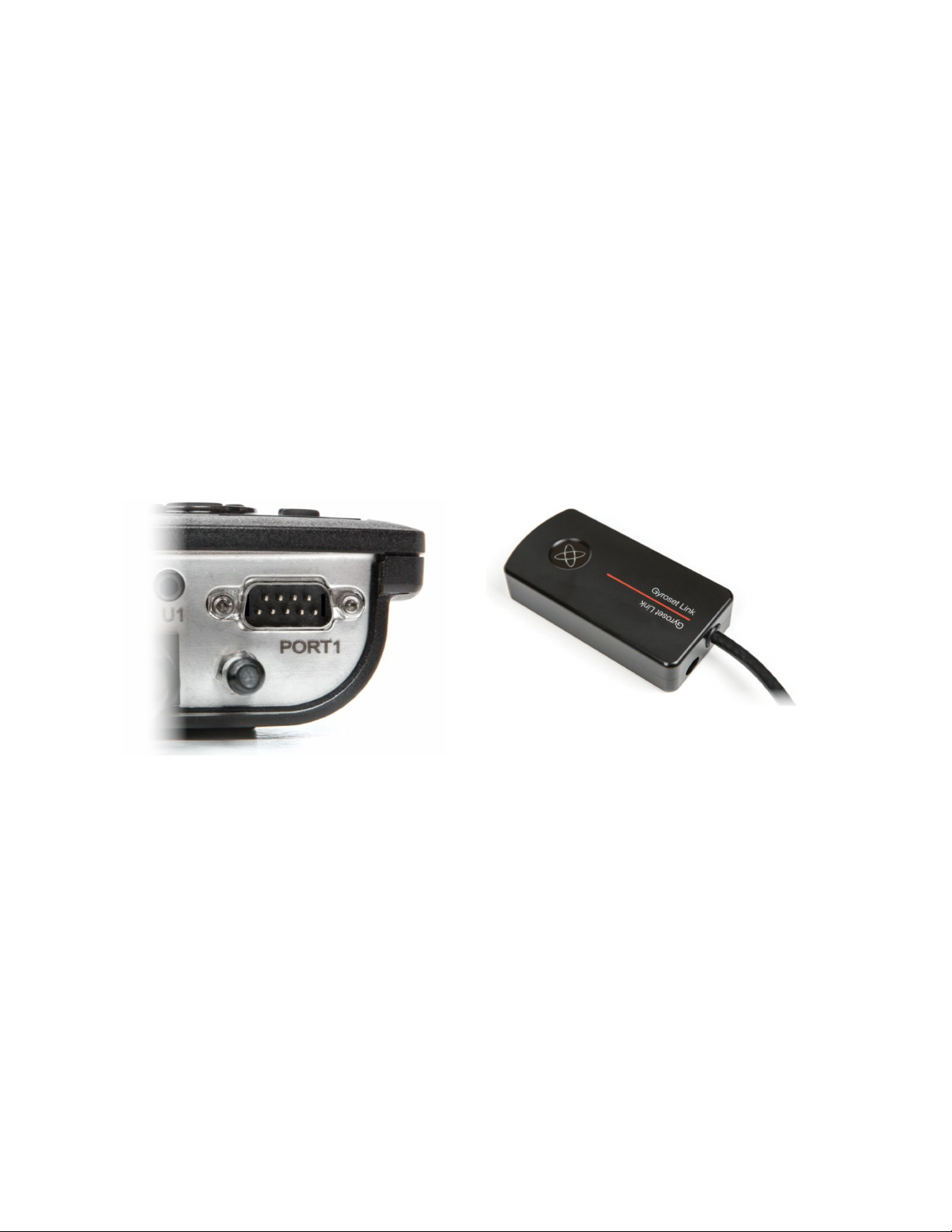
On the GyroSet Link there are two connector interfaces. One of which is an integrated cable
with a D-type connector on it to control the Omni (referred to as Omni cable) and another
oval-shaped interface to connect the GyroSet Glory cable (referred to as Data cable).
Omni Port-1 D-type connector
The two interfaces of the GyroSet Link
(on the left oval shaped data connector)
The preferred SID port, if there is only one input device connected to the Omni, is Port 1 as
shown in the picture below. In case of PGDT IOM there is only one INPUT port where the
D-type connector can be connected:
Page 16
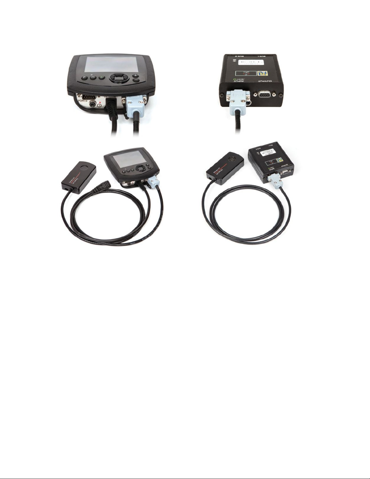
Connecting the GyroSet Link to Omni
Connecting the GyroSet Link to IOM
Please make sure that the wiring meets the following criteria:
● The GyroSet Link must be properly connected to PGDT Omni or IOM or Quantum
Q-Logic 3 via an Enhanced Display or a SCIM Module.
● The GyroSet Link D-type connector connecting to the wheelchair controller must
be secured with screws.
● Cable to the wheelchair must be tied to the frame to avoid accidental tearing or
crushing by the movement of actuators.
● Cable placement has to be designed so that cables are protected during
accidental crashes if the wheelchair hits an obstacle.
● The analog connector should be connected to Omni Port-1 or IOM INPUT only.
In case the Omni’s SID detect function is turned on and the D-type connector has become
disconnected, a screen will appear on the Omni with error code 0905:
Page 17
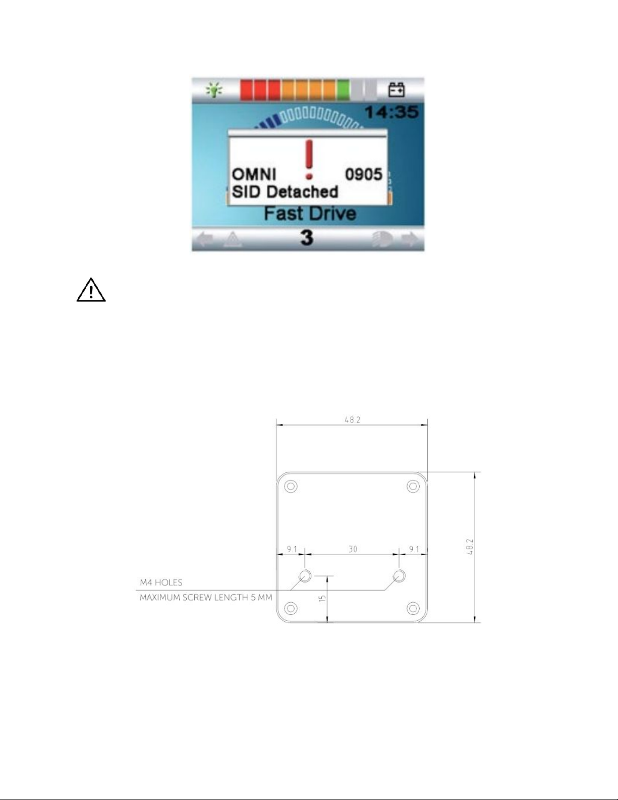
WARNING Always make sure that the chair is configured in a way that the chair’s on/off
switch is available to the user, according to the manufacturer’s guidance.
GyroSet Cubo Mounting
The GyroSet Cubo enclosure has two M4 nuts at the back of the device that is designed
specifically for mounting. As every vehicle and user is unique there is no general mounting
bracket available.
❏ Devices that may produce radio interference, such as Smartphones, Pagers, Bluetooth
devices must be kept out of the way and placed at a distance from the GyroSet Cubo.
❏ GyroSet Cubo should be placed so that the display is visible for the user and the
assistant / carer as well.
Page 18
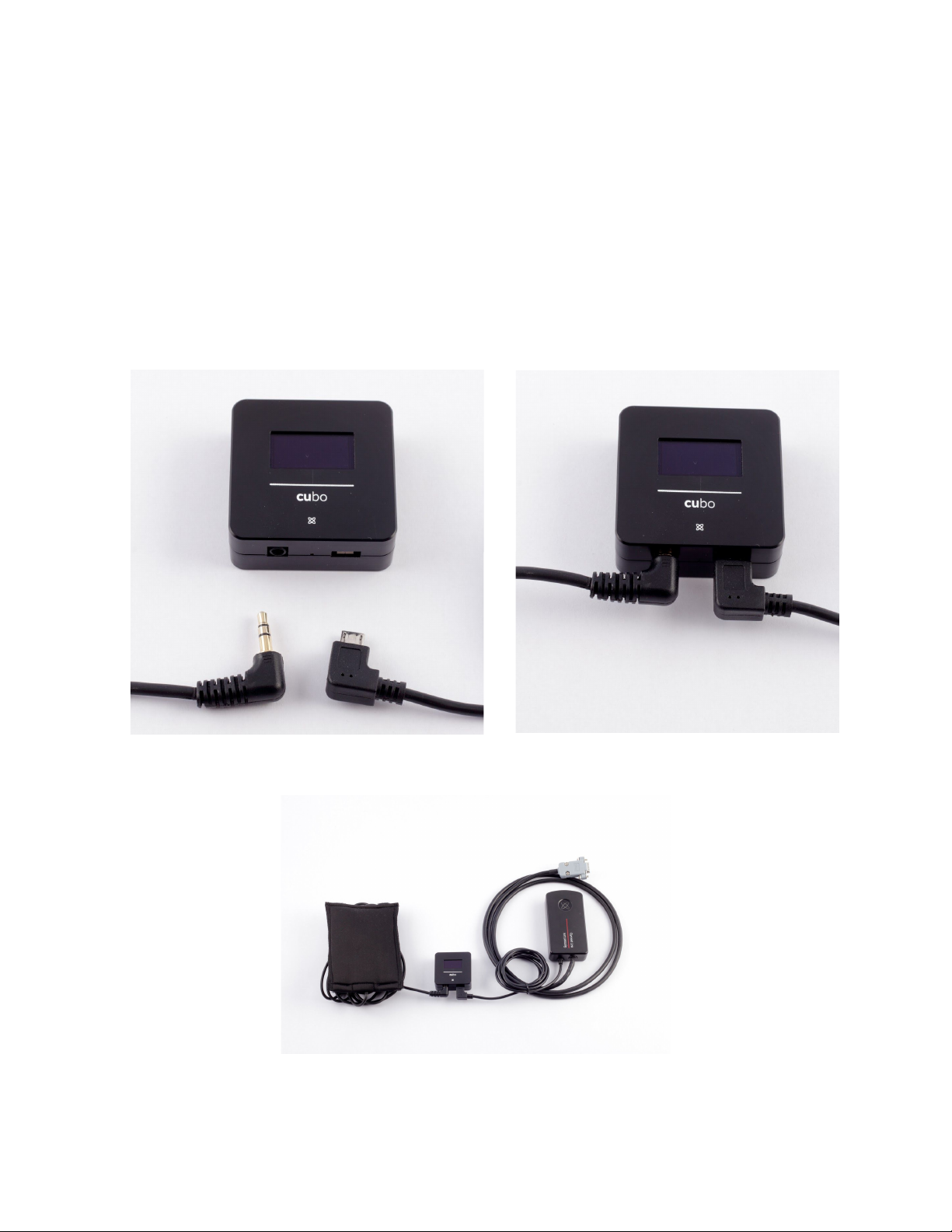
❏ To take advantage of the IP54 protection of the casing, cables must face the ground to
prevent rain getting into the connector:
❏ We recommend placing the Cubo on the same side as the user wears the Vigo.
❏ Please make sure that the placement of the GyroSet Cubo allows for protection against
mechanical damages (e.g. falling objects) for the display.
Connecting the GyroSet Cubo to the Link and to the Headrest Sensor
Headrest Sensor Connector
Link Connector
Please make sure that the wiring meets the following criteria:
Page 19
● The GyroSet Cubo must be properly connected to GyroSet Link and the Headrest
Sensor.
● The GyroSet Cubo Micro-USB and the headrest’s cable must be tied to the frame
of the wheelchair to avoid accidental tearing or crushing by the movement of
actuators.
● The GyroSet Cubo Micro-USB and the headrest’s cable placement has to be
designed so that cables are protected during accidental crashes if the wheelchair
hits an obstacle.
Headrest and Headrest Sensor
For safety reasons we strongly recommend using the Headrest Sensor as it has been
designed to fulfil both emergency stop and drive start functions while enabling the users
to rest their head while not driving.
Jack connector on Cubo
Jack connector is the interface for connecting auxiliary buttons and sensors to the system. The
route of the signal coming from the button can be redirected to be processed by either the Cubo
itself or by the Link. By default the signal is processed by the Link.
● The Link as receiver is compatible strictly with sensors and buddy buttons manufactured
by Now Technologies Ltd. - such as the Headrest Sensor.
● In case the Cubo is set to receive Jack signals any kind of Now Technologies or third
party buddy button can be used.
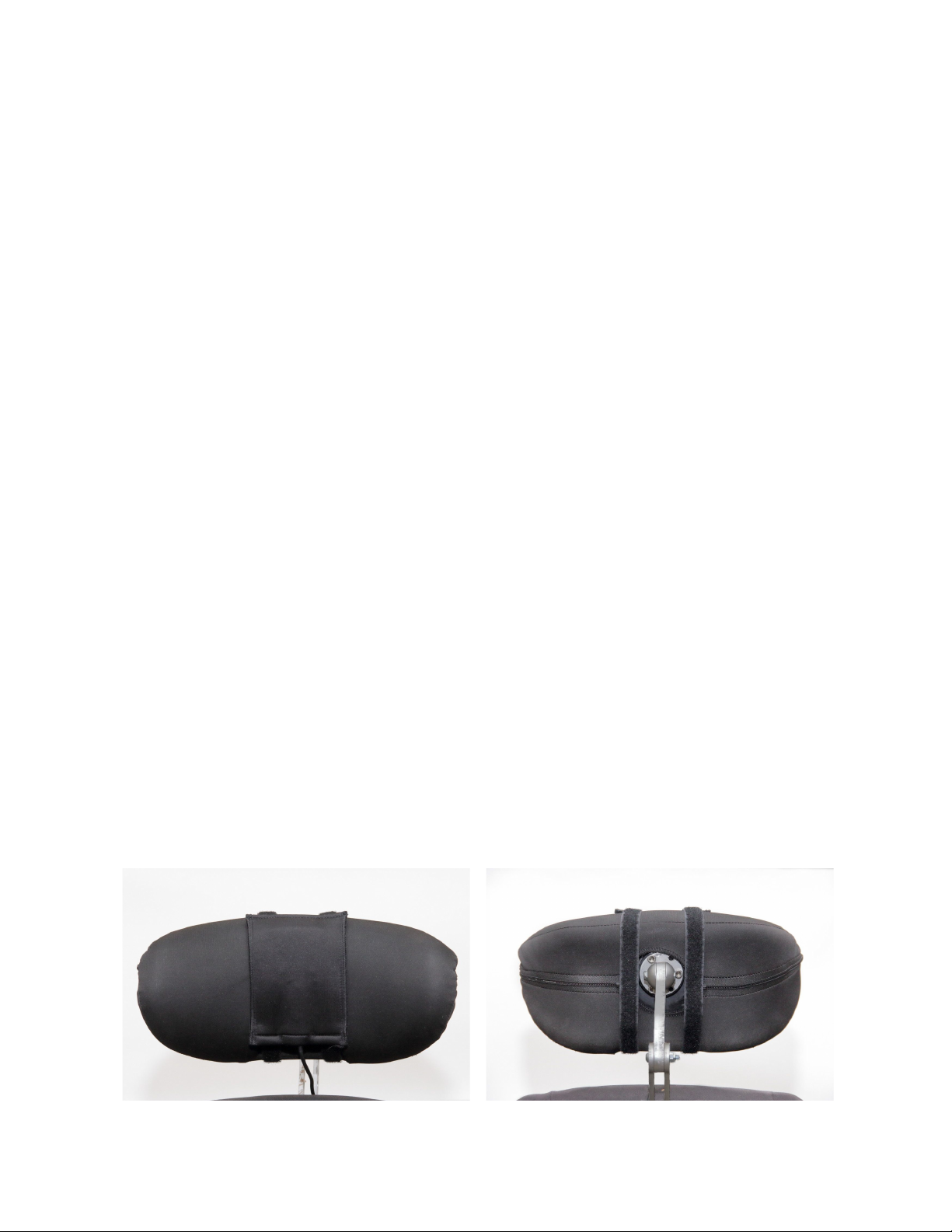
How to place the Headrest Sensor on the wheelchair
Page 20

Please make sure that the wiring meets the following criteria:
● The Headrest Sensor must be properly connected to GyroSet Cubo.
● The Headrest Sensor’s cable must be tied to the frame of the wheelchair to avoid
accidental tearing or crushing by the movement of actuators.
● The Headrest Sensor’s cable placement has to be designed so that cables are
protected during accidental crashes if the wheelchair hits an obstacle.
● The Headrest Sensor must be tied to the headrest by the reusable tie and strap in a way
that it won’t move during extended periods of usage.
● Please make sure that the position of the Headrest Sensor is easily reachable for the
specific user during driving.
Page 21

Setting up the System
Setting up the Omni and the GyroSet Link
Please find our tutorial videos on https://www.nowtech.hu/tutorials/
GyroSet Link and the GyroSet Cubo enables GyroSet Vigo users to use their GyroSet Vigo on a
PGDT Omni or IOM equipped wheelchair as a specialty input device (SID). The Omni is a
universal specialty controls interface that accepts signals from many different types of SIDs and
translates them into commands compatible with the PG Drives Technology R-Net control
system.
Programming the Omni
For programming the Omni please follow the instructions provided by Penny and Giles Drive
Technologies. There are three methods of programming the Omni. Details of
the actual programmable parameters are given in the SK78813 Programming chapter. Ensure
the R-Net Control System’s Drive, Acceleration and Deceleration settings are at a comfortable
and safe level prior to attempting to program the Omni to suit the user.
Refer to the R-Net Technical Manual SK77981 or the On-Board Programming Manual SK78571
for details of how to program the R-Net Control System. Programming should only be conducted
by professionals with in-depth knowledge of PG Drives Technology electronic control systems.
Incorrect programming could result in an unsafe set-up. Now Technologies Ltd. accepts no
liability for losses of any kind if these conditions are not met.
Page 22
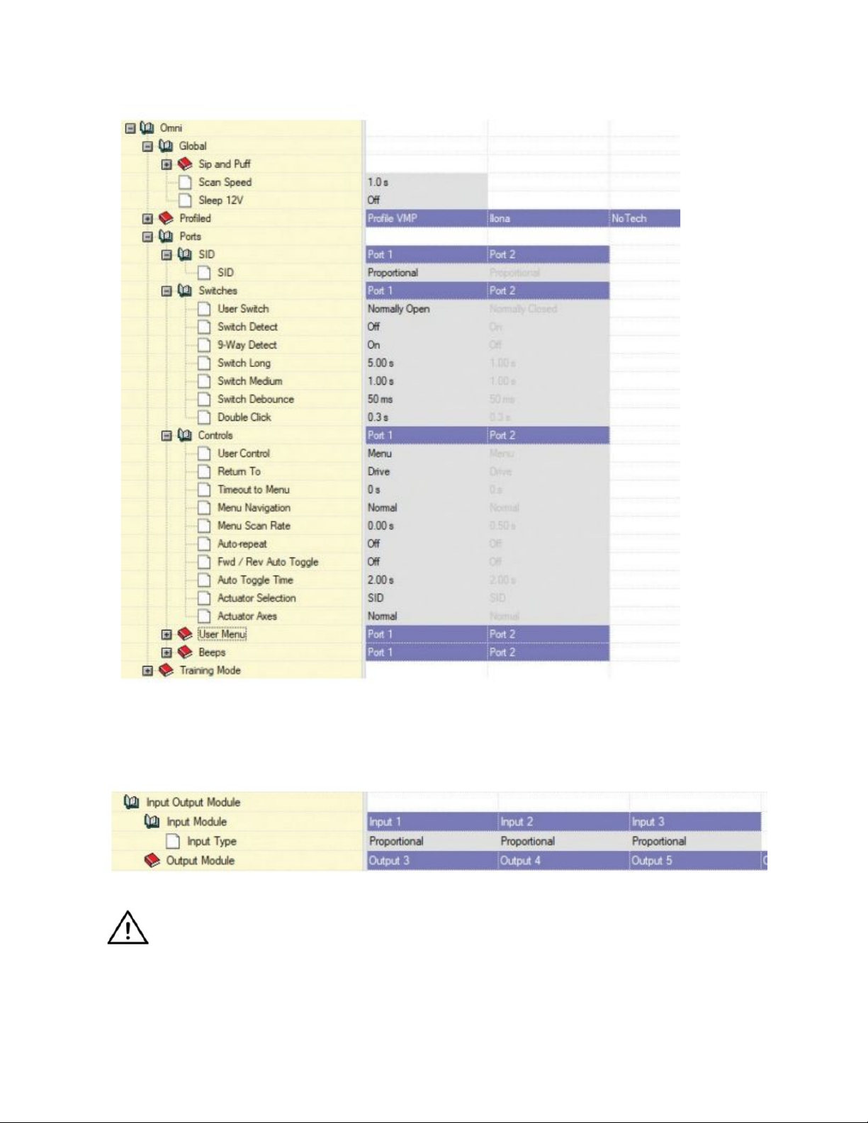
Using the R-Net PC programmer to configure Omni, Port 1 SID has to be set to proportional.
To use the Click sensor of the GyroSet Vigo to activate menu functions on the Omni, Port 1
User control has to be set to Menu and Return To Drive.
WARNING The Omni can be put to sleep by selecting that option in the User Menu. To
wake the Omni, the following SID sequence is required: Left, Right, Left, Right. Note,
this waking method only works if the Omni has been put to sleep via the User Menu.
For that to work “Sleep 12V” parameter has to be turned off to allow the GyroSet Link to operate
constantly. For safe operation of the chair Now Technologies doesn’t recommend the
Page 23

above-described scenario, instead please install the Headrest Sensor within the reach of the
User that can act as an emergency stop as well. For more instructions, see the “Headrest and
Headrest Sensor” section.
Please make sure that your R-Net configuration meets the following criteria:
• The correct SID port is configured as proportional.
• Sleep 12V parameter is set.
• User control is set.
• Drive, Acceleration and Deceleration settings are at a comfortable and safe level.
To avoid control problems when changing your seating position, we recommend
modifying your setting in the Omni to allow control of the actuators only when the head
is tilted either to the left or right side.
Setting up the IOM and the GyroSet Link
Setting up the IOM with the GyroSet Link should only be conducted by the distributor or a PGDT
trained person.
Setting up the Dynamic Controls Linx DLX-IN500 and the GyroSet Link
Setting up the Dynamic Controls Linx DLX-IN500 with the GyroSet Link should only be
conducted by the distributor or a Dynamic Controls trained person.
Setting up the Quantum Rehab Q-Logic 3 EX Enhanced Display or SCIM
Module and the GyroSet Link
Setting up the Quantum Q-Logic 3 EX Enhanced Display or SCIM Module with the GyroSet Link
should only be conducted by the distributor or a Q-Logic trained person.
Setting up the Vigo
The GyroSet Vigo was paired to your system at the factory.
Pairing to your phone (optional: to receive calls and listen to auditory type
entertainment)
1. In the mobile phone Settings, turn on Bluetooth. (iOS and Android: Settings > Bluetooth
> On)
Page 24

2. To pair Vigo with your mobile phone, press and hold the Vigo Multifunction Button for 7
seconds. The Alert LED will flash alternating red and blue.
3. In your mobile phone Settings, search for new Bluetooth devices.
4. Select “Vigo”.
5. Once successfully paired, the Alert LED will stop flashing, and you will hear “Connected”
spoken from the Vigo earpiece.
GYROSET LINK CONFIGURATION
Personalize the driving experience
1. Download and install the Glory Tools software from our website:
https://nowtech.hu/downloads/ After the installation, the Glory Tools application should
start running automatically (depending on the operating system version and the setup of
your computer).
2. Insert the Glory Dongle into the computer’s USB port.
3. Turn on the Omni. This will turn on your GyroSet Link and your GyroSet Cubo.
4. Put the Link into Service mode with a long press on its touch button (the Now
Technologies logo).
5. In Glory Tools, go to GyroSet Settings → Link. For further information, click the Help (?)
icon in the top right corner or download the Glory Tools Help document from
https://nowtech.hu/downloads/
The GyroSet Link translates the user’s head movements into analog joystick sweeps. For that to
function correctly all GyroSet Link parameters must be set according to the individual user’s
needs. The configuration of the GyroSet Link can be achieved through the Glory Tools
application - available for all users - that provides an interactive Help and settings Wizard, which
you can find by clicking on the question mark icon in the top right corner of the application on
any page. The GyroSet Vigo can measure the tilting of the head in the four main directions,
forward, backward, left and right.
Setting the driving parameters in the OMNI for safe and smooth acceleration
Page 25
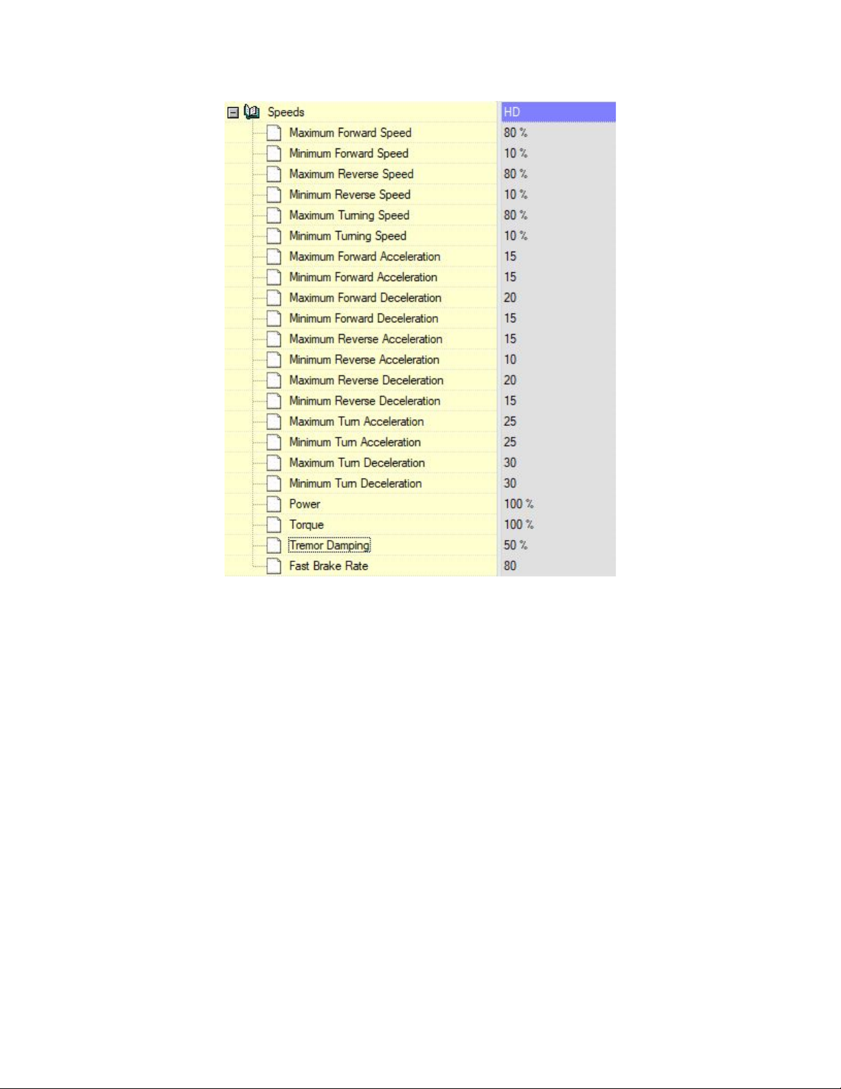
1. Based on the factory default parameters, and according to the results of the test drive with a
joystick, the assistant shall identify the highest speed values of the chair that enables the user to
drive the chair safely:
1. Maximum Forward Speed
2. Maximum Reverse Speed
3. Maximum Turning Speed
2. It is recommended to set both acceleration and deceleration speeds to a relatively low value
in order to avoid the swinging of the head. This could disturb the operation of the sensors.
● Maximum Forward Acceleration: 15-35
● Maximum Forward Deceleration: 20-40
● Maximum Reverse Acceleration: 15-35
● Maximum Reverse Deceleration: 20-40
● Maximum Turn Acceleration: 25-45
● Maximum Turn Deceleration: 30-40
3. The assistant shall validate the drivability of the chair by using the chair themselves.
Page 26

Twitch of the chair during acceleration, deceleration or especially driving forward can be caused
by the swinging of the head. In this case, we recommend increasing the value of the Tremor
Damping from zero step by step, until the chair is able to accelerate without twitches.
4. The end-user should validate the driving parameters by driving the chair with the GyroSet
Vigo. The assistant shall modify the maximum speed values and the value of the Tremor
Damping according to the user’s needs.
5. It is recommended to create a copy of the final profile as a basis for other profiles. When for
example the user needs a second profile for indoor driving, it is enough to use the copy of the
outdoors profile and change only the maximum forward speed value and leaving the rest
untouched.
The above-mentioned example values and ranges can greatly differ from user to user. It is
recommended to always follow the above process when setting values to gain safe driving and
smooth acceleration.
Page 27
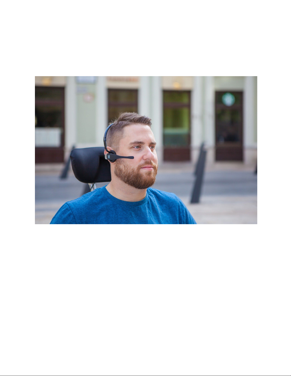
How to wear and drive with the GyrsoSet Vigo
How to wear the Vigo
1. Find a comfortable seating position for the user and adjust the headrest so that the
Headrest Sensor is always in reach for the user (3-5 cm). Pushing the Headrest Sensor
with the back of the head should always be an easy operation. Try to do that several
times and adjust your chair/wheelchair’s seating or headrest position if required.
2. Try the Vigo on the user’s head. Adjust the headband in a way that it sits firmly on the
top of the user’s head, and they can wear it comfortably for hours. To ensure operational
efficiency, adjust the Vigo on the head. The sensor should be placed approximately 3 cm
from the movable parts of the user’s face (corner of the eye, cheek, corner of the mouth,
etc.)
Page 28
Turn on the System (for assistants/carers)
1. To turn on the Vigo, press and hold the Multifunction Button on the Vigo for 5 seconds.
The Alert LED will flash 3 times, Vigo will vibrate once, and you will hear “Power on”
spoken from the Vigo earpiece if it’s close enough to your ears.
2. Put the Vigo safely on the head of the user: place it on the user’s head, adjust the click
sensor’s flexible tube as described in this Manual. The sensor should be placed
approximately 3 cm from the movable part of the user’s face (corner of the eye, cheek,
corner of the mouth, etc.)
3. Turn on the Omni. This will turn on the GyroSet Link and the GyroSet Cubo
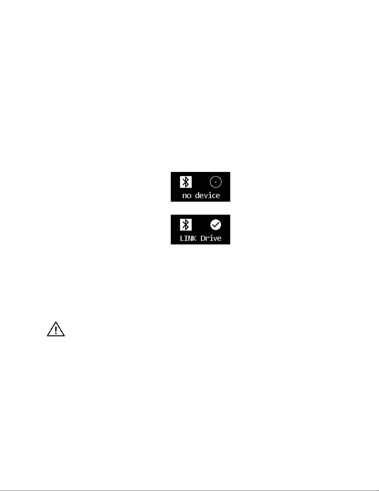
4. You will see the Bluetooth icon of the Cubo flashing and a No device text.
5. The Cubo will recognize the Vigo and the text “Link Drive” will appear.
6. Ask the user to push the Headrest Sensor, and when she starts hearing the sounds,
push it again before the sounds are over. This will activate the Drive mode and
Deactivate again to finish the calibration process. At the end of the process, the Link will
be in an inactive state.
For other status displays, please see the GyroSet Cubo System Status Feedback
section in the Appendix.
WARNING If you ever experience that the chair is not exactly following your directions,
stop driving and recalibrate the system. Follow the direction above and after Set 5. Put
the Vigo on a stable and flat surface (usually 5-10 seconds) until the calibration icon
changes to a checkmark. Continue the process with Step 7.
Driving with the GyroSet Vigo
Switch modes with the Vigo
The default mode after the turn-on process is inactive drive mode.
Driving:
To start driving, press the Headrest Sensor with the back of the head shortly (0-1 seconds).
Page 29

Emergency stop/Leave driving mode:
Push the Headrest Sensor with the back of the head with a fast (faster than reversing)
movement. The chair will react immediately to the push of the sensor.
The chair stops also when the head leaves the range set in the Glory Tools application and also
when the user is making fast, seizure-like movements.
Enter the Omni menu:
When the driving mode is inactive, use a face-wink gesture to enter the menu of the Omni.
To be able to navigate in the menu, the head drive needs to be in active mode, please use the
Headrest Sensor to activate navigation in the menu.
WARNING Please do not leave the Omni menu by the Exit option in the menu as this
will cause you immediately driving the chair. Instead, deactivate the menu navigation
first by using the Headrest Sensor and then switch to drive mode with a face-wink to
continue driving.
Resting:
Tap the Headrest Sensor quickly with the back of the head with a fast movement and hold your
head on it for at least 5 seconds. That will enable you to rest your head without the risk of
accidentally starting to drive.
Drive with your Vigo
1. Imagine that your head is like a regular joystick.
2. Tilt your head (make sure not to turn as it has no effect) to the direction you wish to go.
The tilt amount is proportional to the speed of the wheelchair’s movement. Make slow,
fluid and small movements with your head to avoid activating the emergency stop.
3. To come to a halt, move your head into the neutral position (into the dead-zone)
4. To stop driving press the Headrest Sensor.
For each drive session, a new neutral position can be selected, this helps in case the user
changed their posture.
Page 30

Using the OMNI Menu
1. To avoid control problems when changing your seating position, we recommend
modifying your setting in the OMNI to control the actuators only with head side tilts.
2. When the chair is not moving the GyroSet Vigo’s click sensor (face wink) can be used to
enter into the Omni Menu.
3. Activate the head drive - by tapping firmly the Headrest Sensor - to navigate the menu.
4. Your head will act as a joystick to help you go through all the available preferences.
5. Select menu items with tilting your head right as with a joystick, but make sure to return
to the neutral position
6. Use the face wink gesture again to deactivate the Omni menu navigation.
Other GyroSet Vigo Functions:
Answer and incoming call
Short-press the Multi-Function Button to answer the incoming call.
End a call
Short-press the Multi-Function Button to end the current call.
Reject a call
Long-press the Multi-Function Button for 2 seconds to reject the incoming call.
Adjust the volume
Press “VOL+” to increase volume. You will hear “beep” from the GyroSet Vigo earpiece.
Press “VOL-” to decrease volume. You will hear “beep” from the GyroSet Vigo earpiece.
Play/Pause
Short-press the Multi-Function Button to play/pause the music.
Page 31

Power off
To power off GyroSet Vigo, press and hold the Multi-Function Button for 5 seconds. The Alert
LED will flash blue 3 times, and you will hear “Power off” spoken from the GyroSet Vigo
earpiece.
Battery charging & battery level
Charging: Use the included USB cable for charging. The Alert LED will turn red while charging.
Charging time: 2 hours. When fully charged, the Alert LED will turn off.
Low battery: You will hear “Low battery” spoken from the GyroSet Vigo earpiece.
Music streaming
Streaming audio is initiated and controlled by your mobile phone.
When a call rings, any streaming audio will automatically pause, to enable you to answer the
call. When the call is ended, the streaming audio will resume.
Play/Pause: Click the Multi-Function Button once.
Previous song: Ling-press “Vol+” for 2 seconds.
Next song: Long-press “VOL-” for 2 seconds.
Sleep mode
GyroSet Vigo will enter sleep mode after 3 minutes of no blink detected or no interactions.
GyroSet Vigo Product Specifications
1. Bluetooth operating range: Up to 30 feet
2. Talk time: 10 hours
3. Audio playtime: 10 hours
4. Standby time: 10 days
5. Charging time: 2 hours
6. Bluetooth version: 4.0
7. Bluetooth profile: Support HFP, HSP and A2DP
8. Charging: Micro-USB
9. Noise cancellation: Dual MEMS microphone technology
Page 32

Appendix
GyroSet Vigo LED Indications:
Solid Red on: Charging
Off (with USB power applied): Fully charged
Flashing Red: Vigo is on low energy
Alternating Red and Cyan: Vigo in pairing mode
Flashing Red, Green and Blue: Vigo power on (or off)
LED flash blue once every 5 seconds: Vigo standby (without connecting to a phone)
LED flash cyan once every 7 seconds: Vigo working mode (connect to a phone) or playing
music
LED double-flash cyan once every 3 seconds: incoming call, answer a call or dial-out
GyroSet Link LED (GyroSet Logo) Indications:
Colour
Light pattern
Status
None
No
The device is turned off or in sleep
White
Breathing: fade in – fade
out
The device is turned on, but there is no
headset
Blue
Breathing: fade in – fade
out
Connection to the headset established through
RADIO and IDLE
Blue
Blinking
Connection to the headset established through
RADIO and ACTIVE
Green
Breathing: fade in – fade
out
Connection to the headset established through
CABLE and IDLE
Page 33
Green
Blinking
Connection to the headset established through
CABLE and ACTIVE
Orange
Breathing: fade in – fade
out
GyroSet Link is in Service Mode
Red
1 short high sound signal
System halted due to an error. Driving stopped
Blue
Rapid blinking
Waiting for centering the head (RADIO
connection)
Green
Rapid Blinking
Waiting for centering the head (CABLE
connection)
GyroSet Link Audible feedback:
Please note that you can mute/unmute all Link sounds by a short touch on the GyroSet logo.
Description
Meaning
. –
one short and low sound followed by a longer
and higher sound
Linked turned on
. –
one very short, lower sound, followed by a
longer and a little bit higher sound
Start driving
. _
one very short higher sound followed by a
longer and a little bit lower sound
Stop driving
—
—
—
one very long sound repeating continuously
Reversing
.
one short, high sound
Fifth down
.
one short, high sound (a bit lower than fifth
down)
Fifth up
.
one very short sound of average height
Set center/waiting
.
one very short beep sound
Mute
Page 34
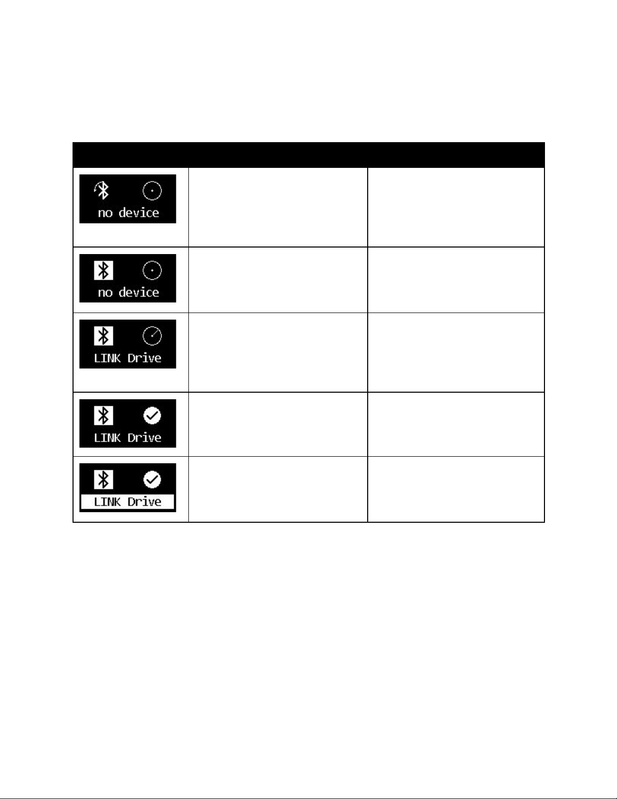
GyroSet Cubo system status feedback
Description
Meaning
An arrow is running around the
Bluetooth icon in a
counterclockwise direction.
A circle and a “no device” label is
visible.
The system lost its binding with
the GyroSet Vigo and is looking
for the first GyroSet Vigo it is able
to find.
The Bluetooth icon is flashing. A
circle and a “no device” label is
visible.
The system is bound to, but
doesn’t have connection with
theGyroSet Vigo and is looking
for it.
The Bluetooth icon is highlighted.
The clock hand in the circle is
flipping. A “LINK Drive” label is
visible.
The system is connected and is
being calibrated. To enable the
system to finish calibration, the
GyroSet Vigo has to be in a
stable, resting position.
The Bluetooth icon is highlighted.
A check mark icon is highlighted.
A “LINK Drive” label is visible.
The system is connected and
ready for drive, but the drive
mode is passive.
The Bluetooth icon is highlighted.
A check mark icon is highlighted.
The “LINK Drive” label is
highlighted.
The system connected and is in
an active drive mode.
Page 35

SPECIAL SAFETY CHECKLIST
Please make sure that the following criteria are met before trying to drive the wheelchair
with the GyroSet Drive System:
❏ Understanding of the intended use of the GyroSet Cubo and the GyroSet Vigo by getting
familiar with this User Manual.
❏ The adjustment of the headrest: The user must be able to reach the Headrest Sensor at
any time to be able to activate it.
❏ The intended direction of movement must be set by using Glory Tools.
❏ The user’s head movement range must be set by using Glory Tools.
❏ Out of operation range for the faint detection threshold must be set using Glory Tools.
❏ Tremor filter must be set using Glory Tools.
❏ Click sensor functions and parameters must be set using Glory Tools.
❏ Click sensor long-press maximal timeout must be set using Glory Tools.
❏ Centre mode and parameters must be set using Glory Tools:
❏ Please make sure to check if the center mode is set to “Countdown” in Glory
Tools. If yes, the “Timeout” has to be set.
❏ The maximum speed, acceleration, deceleration of the head drive profile of the
wheelchair controller must be adjusted:
❏ Settings of the controller must be administered specifically trained and authorized
personnel.
❏ Acceleration and deceleration settings of the wheelchair shall not cause inertia
on the user’s head that the user cannot compensate.
❏ Maximum speed must always be in accordance with the local regulations.
❏ The service network must be used only for the time when changes are made to the
personal drive profile.
❏ The user should avoid:
❏ Environments with extreme radio interference when driving wirelessly as it may
cause the wheelchair to stop if it receives no signals.
❏ The user shall be aware of the fact that the GyroSet Link must be selected by using the
Headrest Sensor for control with the GyroSet Vigo.
❏ The user must be trained and know how to handle the center detection (jump to center).
❏ In case the mode is set to countdown, the user’s head shall be motionless in a
neutral position after activating the drive function for a few seconds until the
countdown stops.
❏ In case the mode is set to automatic, the drive won’t start until the head is put
into a motionless state for less than a second.
❏ Be aware that the GyroSet Vigo acts as a joystick within the R-Net control system:
Page 36

❏ By programming the wheelchair controller, various functions can be tied to “fifth
button” presses, in this case, the click sensor of the GyroSet Vigo.
❏ When the fifth button’s long-press timeout is set to a smaller value on the R-Net
than on the GyroSet Link the click sensor can turn the chair into sleep mode.
❏ In case the fifth button function is programmed so that the User can access the
Omni menu, the GyroSet Vigo can be used to navigate within the menu using
head gestures similar to the controller’s joystick.
❏ In case the fifth button function is programmed so that the User can control
actuators, the GyroSet Vigo can be used to move the actuators using head
gestures similar to the controller’s joystick.
❏ After the drive mode is initiated a distinguishable audio feedback can be heard.
❏ The chair will move according to the head movements and the profile settings of
the GyroSet Link and the controller.
❏ The chair will move until the function is deactivated or failure is detected. The
chair stops immediately if a failure is detected, a cable is unplugged or wireless
signal is lost.
❏ The chair can be stopped while in drive mode by moving the user’s head to the
initial neutral position.
❏ In case the center of driving feels off compared to the initial center, the user shall stop
and reinitiate drive, taking on a new center/neutral position.
❏ That depletion of the GyroSet Vigo’s battery will cause the chair to stop.
❏ The GyroSet Vigo’s battery must be charged on a daily basis.
❏ If the GyroSet Vigo falls off, the chair stops.
❏ A sudden backward movement of the head inside the turning dead zone will force the
system to execute an emergency break of the chair.
❏ In case the user’s head reaches the maximum of the range of operation the sweep of the
head joystick is at maximum.
❏ If the user’s head reaches the safety zone in any direction the chair will stop.
❏ If the user’s head is in the range of the center dead zone the chair won’t move or it will
stop.
WARNING The microcontroller is protecting the firmware with built-in hardware fuses,
any attempt on reading or modifying the content of the flash will fail. All user-related
variables are encrypted, any attempt on gaining access to secure data will erase the
chip content.manufacturer’s guidance.
Page 37

WARRANTY
Now Technologies Ltd. provides two year’s full warranty on the products. This warranty covers
any defects in materials or workmanship, with the exceptions stated below:
Faults resulting from the installation by an unqualified person. Any problem that is caused by
abuse, misuse, extreme water damage or extreme weather are not covered. Also,
consequential and incidental damages are not recoverable under this warranty.
Revision History
Revision number
Change log
Date of release
01
Original content
30 November 2019
Page 38

EUROPEAN UNION – DISPOSAL INFORMATION
The symbol above means that according to local laws and regulations your product and/ or its
battery shall be disposed of separately from household waste. When this product reaches its
end of life, take it
to a collection point designated by local authorities. The separate collection and recycling of
your product and/or its battery at the time of disposal will help conserve natural resources and
ensure that it is recycled in a manner that protects human health and the environment.
EXPOSURE TO RADIO FREQUENCY
The GyroSet Glory has been tested and meets applicable limits for radio frequency (RF)
exposure.
Specific Absorption Rate (SAR) refers to the rate at which the body absorbs RF energy. The
SAR limit is 1.6 watts per kilogram in countries that set the limit averaged over 1 gram of tissue
and 2.0 watts per kilogram in countries that set the limit averaged over 10 grams of tissue.
During testing, GyroSet Glory radios are set to their highest transmission levels and placed in
positions that simulate uses against the head, with no separation, and when worn or carried
against the torso of the body, with 5mm separation.
Page 39
EU COMPLIANCE STATEMENT
Now Technologies Ltd. hereby declares that this wireless device is in compliance with the
essential requirements and other relevant provisions of the R&TTE Directive and Radio
Equipment Directive 2014/53/EU, as applicable. Now Technologies’s EU representative is Now
Technologies Ltd. 18. Reáltanoda street, Budapest, 1053 Hungary.
The GyroSet Drive components contain modules with the following FCC IDs:
GyroSet Link:
FCC ID: W7OMRF24J40MDME
GyroSet Cubo:
FCC ID: 2AC7Z-ESPWROOM32D
GyroSet Vigo:
FCC ID: 2AFKV-VIGO
GyroSet Dongle:
FCC ID: OA3MRF24J40MA
www.nowtech.hu
RoHS DECLARATION OF CONFORMITY
We hereby declare that our products are compliant to RoHS Directive 2011/65/EU of the
European Parliament and the Council from 08/06/2011 on restriction of the use of certain
hazardous substances in electrical and electronic appliances.
Now Technologies Ltd. herewith declares that all of our products are manufactured in
compliance with RoHS.
 Loading...