

Page 1
NL Installatievoorschriften p. 4
FR Instructions d’installation p. 8
DE Montageanleitung p. 11
EN Operating and installation Instructions p. 15
6830/16 - 6831/16
6840/16 - 6841/16
Page 2
1
3
6
2
4
5
2
12 x 906116
Page 3
87
10 11
13
9
12
14
3
Page 4

EN 15
GENERAL INFORMATION
General
These are the mounting instructions for the Novy unit shown on the cover. The user manual is delivered separately with
this unit. Carefully read these instructions before installing and commissioning this unit. It is recommended to have one
or more qualified persons carry out the installation.
This manual makes use of a number of symbols. The meaning of these symbols are given below.
Symbol Meaning Action
Indication Explanation of an indication on the
hood
Warning This symbol indicates an important tip
or a dangerous situation.
Safety
Observe the following mounting and safety tips for mounting:
• The installation and electrical connection of the unit shall be carried out by an authorised expert.
• The manufacturer does not accept any responsibility for any damage resulting from faulty building in or connection.
• Carefully take the unit from the packaging and check it for damage before mounting.
• Do not mount the unit in case of any damage.
• Check if all mounting materials have been supplied using the drawings at page 2.
• The unit is intended for household use only (preparation of food) excluding any other domestic, commercial or industrial use.
• Safety can only be guaranteed if the unit is connected to an earth wire in accordance with the required regulations.
• Do not use an extension cord for connecting to the electricity grid.
• Replace defective or damaged parts only with original Novy parts.
• Replace a damaged power cable with an original Novy power cable.
Important before mounting
Page 2 of these mounting instructions show the mounting drawings. Observe the following mounting tips before starting
the mounting activities:
• For easier mounting of the ceiling unit, it is recommended to do this with at least 2 persons.
• Make sure that the ceiling has sufficient load bearing capacity.
• Position the wall socket in such a way that it is behind the ceiling unit.
Exhaust or recirculation
Before starting any mounting activities, you must have made the choice if you are going to make an exhaust duct to the
outside or if you are going to use the hood as a recirculation hood. In case of an exhaust duct to the outside, carefully
read the section in these mounting instructions for installing the exhaust duct. If you choose for recirculation, Novy offers
the exhaust box (see accessories).
InTouch
InTouch offers the option to control the Novy cooker hood from the Novy InTouch induction hotplate. The ceiling unit
may, as a default, be combined with InTouch induction hotplates. Visit the website for the different models of induction
hotplates with InTouch
INSTALLATION
Proceed following the mounting drawings on page 2 and 3.
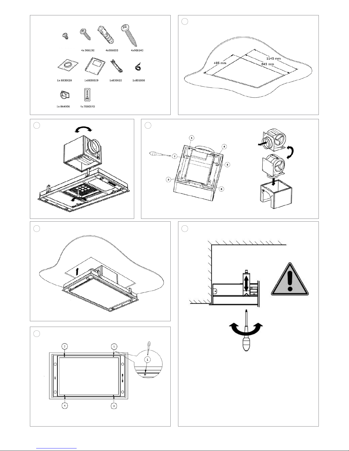
1
Make a build-in opening:
Type 6830 / 6831 – Cut-away 845mm x 485mm.
Type 6840 / 6841 – Cut-away 1145mm x 485mm.
The ceiling unit can be built into plates with a thickness of 18-35mm. Do not mount directly into gypsum board;
always make sure there is reinforcement for the tightening of the mounting clamps. Make sure there is a socket
near the ceiling unit, so that the power may, at all times, be removed from the ceiling unit.
In view of the substantial own weight of the hood, the ceiling must have sufficient load bearing capacity.
The recommended mounting height for an electrical or ceramic cooking plate is min. 600 mm and max. 16000 mm.
The mounting height for a gas or induction cooking plate is min. 650 mm and max. 1600 mm.
Page 5

EN 16
2
Changing the exhaust direction of the motor (if desired).
Sideways:
- Open the bottom plate and remove the filters from the ceiling unit.
- Disconnect the cord that connects the motor to the ceiling unit.
- Loosen the 8 screws located next to the protective grid.
- Turn the motor with the exhaust into the desired position and screw the motor back on using the 8 screws.
3
Changing the exhaust direction of the motor (if desired).
Top:
A Loosen the 6 screws on the motor cover.
B Turn the motor cover a quarter turn and place the motor cover back into the motor housing. Screw it back on again
using the 6 screws.
4
Connect the exhaust duct to the connection nozzle by means of a hose clamp (keep in mind the length of the exhaust
duct in case of removal, if necessary).
Put the plug into the wall socket.
Push the ceiling unit up into the build-in opening by pushing on the edges (not on the bottom plate) until you hear a
firm click. The ceiling unit will now remain suspended in place.
5
Drehen Sie die vier Klemmschrauben von Hand fest, um die Deckeneinheit endgültig zu befestigen. Achtung: drü-
cken Sie dabei die Dunsthaube nicht nach oben und ziehen Sie die Halteklammern nicht zu stark an, da sie sich sonst
unnötig verbiegen. Sobald diese Klemmschrauben festgedreht sind, ist die Deckeneinheit einsatzbereit.
Removing the ceiling unit
6
Before dismounting, protect the cooking plate, for example using cardboard or cloth, in case a screw or clamp is
dropped onto it. To remove the ceiling unit, the 4 clamping screws have to be fully loosened. When these are loose,
the ceiling unit can be taken down. Watch out: the loosened clamping springs may drop down.
Remote installation of the motor unit
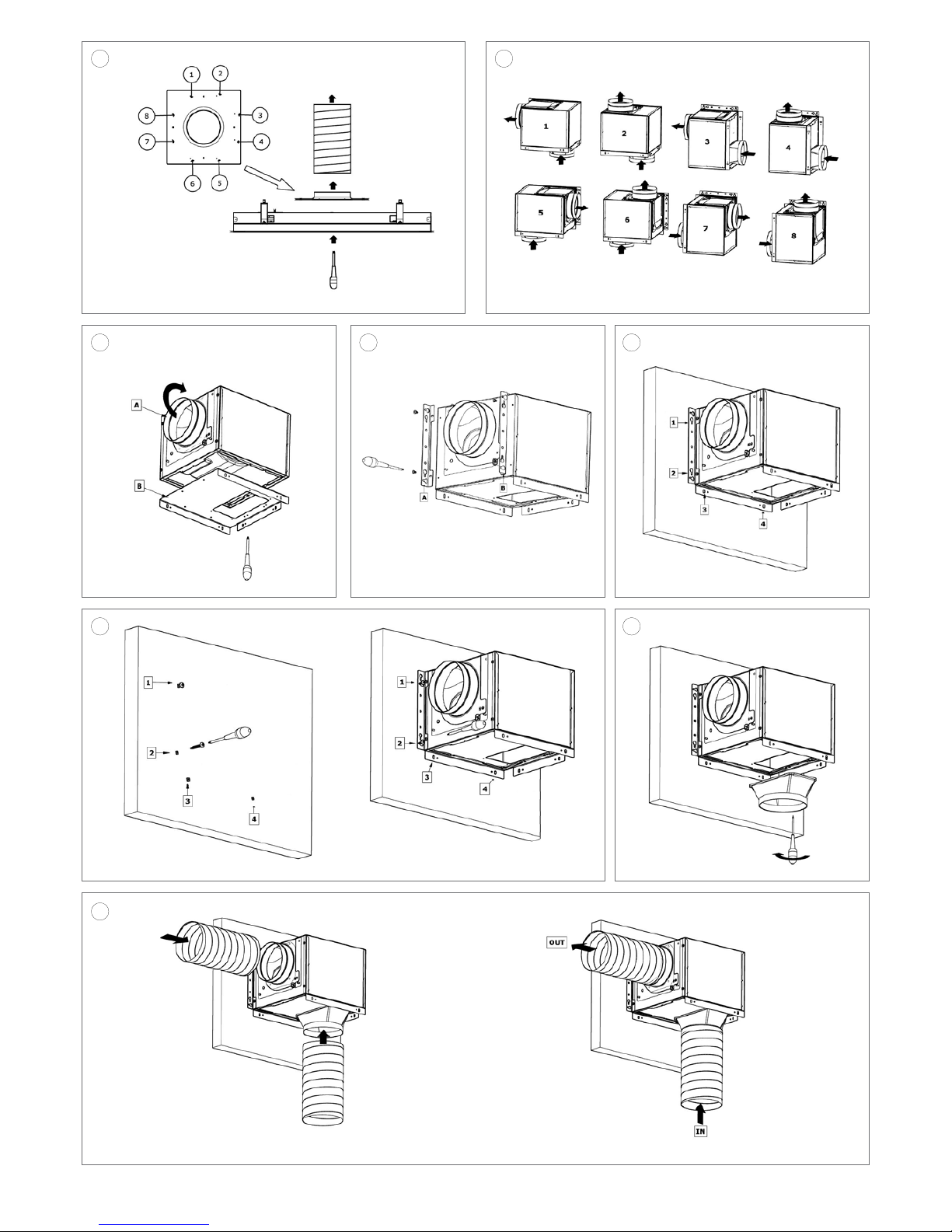
7
Take the motor unit from the ceiling unit by removing the 8 mounting screws (see (2)); use these screws again to
mount the tube adapter to the ceiling unit. You can loosen the plugs on the motor unit.
8
These are the possibilities of the positions the motor unit may occupy.
9
A Determine the location and the suspension position of the motor unit. If necessary, the exhaust direction of the
motor can be changed. The supply and exhaust pipes can be made in a 90° angle or opposite each other.
B Screw the tube adapter (6830029) to the bottom of the motor using the screws (8x 906116).
10
Mount the suspension bracket to the motor housing. This is done by first unscrewing the screws provided from the
motor housing. After this, place the suspension bracket onto the motor unit and screw it back on using the same
screws. You can choose position A or position B.
11
To mount the motor unit onto the wall, you first mark out the 4 drilling holes.
12
To mount onto a stone wall: use the screws 906055 and the plugs 906143.
- Drill the 4 marked-out points and place the plugs into the holes.
- Partly screw in 2 screws in position 1 and position 2.
- Suspend the motor unit over these 2 screws. Next, tighten the screws.
- Now screw in the screws in position 3 and position 4.
To mount onto a wooden wall: use the screws 906192.
- Partly screw in 2 screws in position 1 and position 2.
- Suspend the motor unit over these 2 screws. Next, tighten the screws.
- Now screw in the screws in position 3 and position 4.
13
Connect the plastic exhaust (864006) onto the tube adapter using 4 screws (906116).
14
Mount the suction and exhaust pipe to the motor unit by means of a hose clamp. Connect the plug of the cable co-
ming from the ceiling unit to the plug on the motor unit.
INSTALL THE EXHAUST DUCT
Page 6

EN 17
The motor outlet has a diameter of 150 mm. It is recommended to connect an exhaust duct with a diameter of 150 mm to
this. A reducer is supplied with the hood. Only mount the reducer when using an exhaust duct with a diameter of 125 mm.
For optimum performance of the hood it is important to pay attention to the following points.
Circular ducts:
• Use smooth, non-flammable pipes with an internal diameter that is equal to the external diameter of the connection
nozzle of the hood. Maximally extend flexible ducts and cut them to size.
• Do not reduce the exhaust diameter. This will lower the capacity and raise the noise level.
• When connecting to a short exhaust duct, it may be required to mount a non-return valve in the duct to avoid wind
blowing in.
• Use a hose clamp or aluminum tape for airtight connections.
• In case of an exhaust pipe through the wall, use a wall vent.
Flat duct:
• Use flat duct with rounded corners and with air deflectors. Available at Novy.
General information:
• Make the duct as short as possible and with as few as possible bends to the outside.
• Avoid square bends. Use rounded bends for proper air conduction.
• In case of an exhaust pipe through the outside wall passing a cavity wall, make sure that the exhaust duct fully bridges
the cavity and slightly declines to the outside.
• In case of an exhaust pipe through the roof, use a double-walled roof passage with sufficient width.
• Never connect to a flue duct.
• Make sure that sufficient air is supplied. Fresh air can be supplied by slightly opening a window or an outside door or
by installing an inlet grate.
ACCESSORIES
Adapter for connecting flat ducts
The motor is mounted remotely by using the adapter and you are able to connect a flat duct directly to the ceiling unit.
The advantage is the low build-in height (article number 6830052).
Recirculation
If you choose for recirculation, Novy offers the exhaust box in different sizes, including type 830400 (stainless steel exhaust grid), type 831400 (white exhaust grid), type 7900400 (stainless steel exhaust grid) or type 7910400 (stainless steel
exhaust grid).
Extension cable
When mounting the motor unit remotely, it may be desirable to mount a longer cable between the ceiling unit and the
motor. The extension cable is connected to the existing cable. The extension cable has a length of 5 m.
Various accessories
- Clamp Ø60-215 mm 906291
- Aluminium tape (per 50 m) 906292
- Aluminium wall vent for outlet Ø150mm 906178
- Mechanical wall vent Ø150mm 906419
- One-way valve Ø150mm 906432
- Stainless steel cleaner 906060
Characteristics of the product on condition of changes or printing errors, April 2016
Page 7

NOVY nv behoudt zich het recht voor te allen tijde en zonder voorbehoud de constructie en de prijzen van haar producten te wijzigen.
NOVY SA se réserve le droit de modifier en tout temps et sans préavis la construction et les prix de ses produits.
Die NOVY AG behält sich das Recht vor, zu jeder Zeit und ohne Vorbehalt die Konstruktion und die Preise ihrer Produkte zu ändern.
NOVY nv
Noordlaan 6
B - 8520 KUURNE
Tel. 056/36.51.00 - Fax 056/35.32.51
E-mail : novy@novy.be
http://www.novy.be
France: Tél: 0320.940662
Deutschland und Österreich: Tel: +49 (0)511.54.20.771
Nederland: Tel.: +31 (0)88-0119110 MA6830 V06
 Loading...