

Page 1

NL Installatievoorschriften p. 4
FR Instructions d’installation p. 6
DE Montageanleitung p. 9
EN Operating and installation Instructions p. 11
230
230_10509_MA1
Page 2
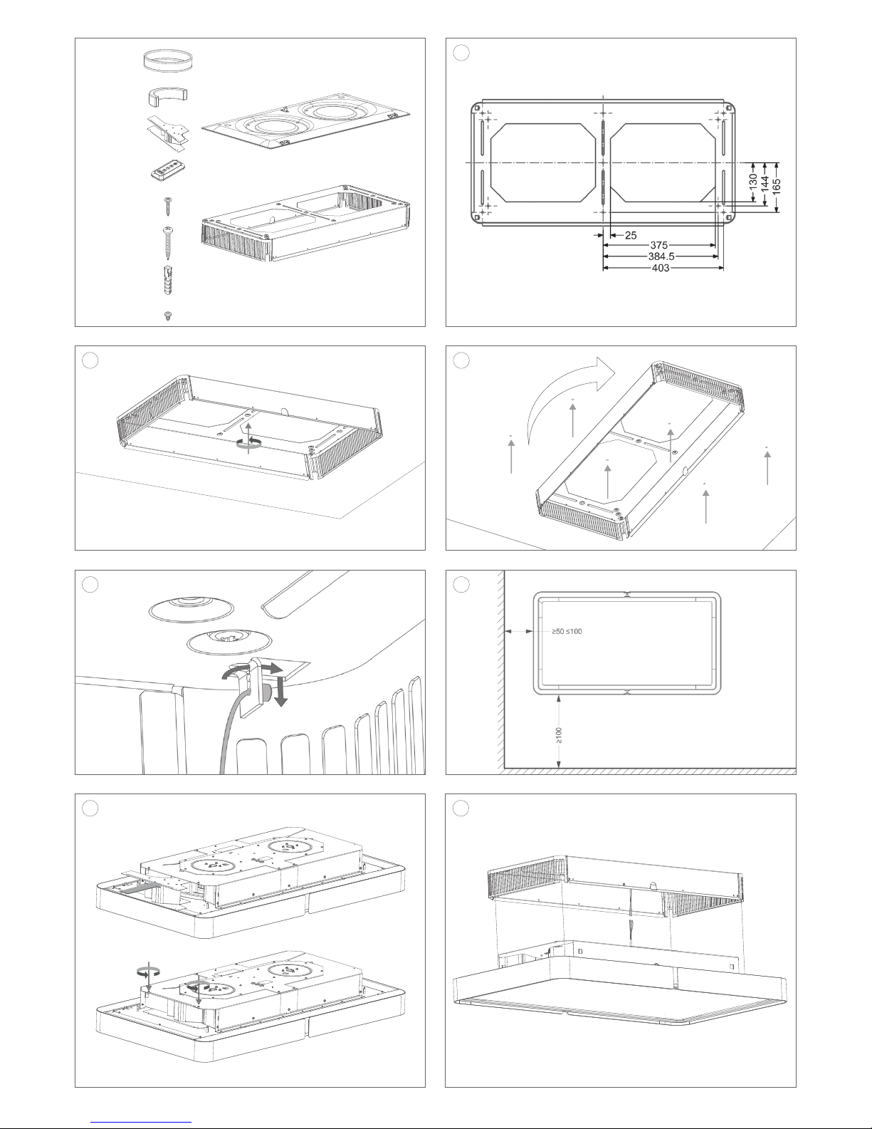
1
2
6
4
3
5a
5b
1x 990.271
1x 840.029
7x 906.192
1x 990.468
1x 990.165
7x 906.143
7x 906.055
11x 906.151
2x 230.020
4x 230.055
Page 3

8a
9
10
8b
7
Page 4

EN 11
GENERAL INFORMATION
General
These are the mounting instructions for the Novy unit shown on the cover. The user manual is delivered separately with
this unit. Carefully read these instructions before installing and commissioning this unit. It is recommended to have one
or more qualified persons carry out the installation.
This manual makes use of a number of symbols. The meaning of these symbols are given below.
Symbol Meaning Action
Indication Explanation of an indication on the
hood
Warning This symbol indicates an important tip
or a dangerous situation.
Safety
Observe the following mounting and safety tips for mounting:
• The installation and electrical connection of the unit shall be carried out by an authorised expert.
• The manufacturer does not accept any responsibility for any damage resulting from faulty building in or connection.
• Carefully take the unit from the packaging and check it for damage before mounting. Do not mount the unit in case
of any damage.
• Do NOT immediately remove the hood from the packaging. Place the box on the table top at the place where the
hood is to be mounted. Take notice of the description on the packaging and open this on the correct side for easy
mounting.
• Check if all mounting materials have been supplied using the drawings in section 2.2.
• The unit is intended for household use only (preparation of food) excluding any other domestic, commercial or industrial use.
• Position the electrical connection such, that it is located in the cabinet in which the cooking unit is mounted
• Safety can only be guaranteed if the unit is connected to an earth wire in accordance with the required regulations.
• Do not use an extension cord for connecting to the electricity grid.
Important before mounting
Page 2 of these mounting instructions show the mounting drawings. Observe the following mounting tips before starting
the mounting activities:
• For easier mounting of the ceiling unit, it is recommended to do this with at least 2 persons.
• Make sure that the ceiling has sufficient load bearing capacity.
InTou ch
InTouch offers the option to control the Novy cooker hood from the Novy InTouch induction hotplate. The hood may, as
a default, be combined with InTouch induction hotplates. Visit the website for the different models of induction hotplates
with InTouch.
INSTALLATION
Follow the mounting drawings on page 2.
1.
Do NOT immediately remove the hood from the packaging. Place the box on the table top at the place where the
hood is to be mounted. Take notice of the description on the packaging and open this on the correct side for easy
mounting.
• Indicate the middle point of the hood. The middle point must be above the centre of the hood
• Draw the centre line in the longitudinal direction.
The mounting height for a gas or induction cooking plate is min. 650 mm and max. 1600 mm.
Because of the substantial own weight of the hood, the ceiling must have sufficient load bearing capacity.
2
• Take the mounting plate (990.468) from the packaging and place it in the centre as seen from the cooking plate
against the ceiling. Make sure that the drawn centre line is aligned with the cut-aways in the mounting plate.
• First draw, drill and fasten the central screw at the indicated middle point.
• Do not fully tighten the screw yet.
Page 5

EN 12
Make sure that the electric connection falls within the left or right opening of the mounting plate.
3.
• Mark the 6 mounting points (in the 4 corners and 2 in the middle of the long sides).
• Carefully turn the mounting plate a quarter turn in order to be able to drill the 6 fastening holes. Turn back the mounting plate and fasten the 6 screws.
• The mounting plate is attached to the ceiling with 7 screws.
4.
4 metal cables have been attached to the hood. - Place these 4 cables in the opening provided in the mounting plate.
5a.
The minimum distance between the left and/or right side of the Cloud up to a wall must be greater than 50 cm.
Only use the air conductor (990.271) in the following situation:
• The distance between the left and/or right side of the hood up to a wall must be between 50 cm and 100 cm. Otherwise go on to step 6.
• When attaching the air conductor, the front where the air is blown must be at 100 cm from a wall.
• This conductor makes sure the air is not blown out vertically to the left or the right, but that it bends away to the front
side of the hood at an angle of 70°.
5b.
Fasten the conductor with 2 screws (906.151) in the hood.
6.
• The hood can be hoisted up using the metal cables. The adjuster can be found at the place where the cable enters
the hood.
• The cable can be extended by pressing this adjuster. The cable will be locked as soon as the adjuster is no longer
pressed. The cable can still be slid in at this moment. Make sure that the cables disappear in the hood.
• Stop about 10 cm below the mounting plate.
• The electric connection can now be made. Attention, do not carry out any mounting activities while the power supply
is switched on. Ensure the power supply has been switched off. And ensure the on/off switch is in the off position.
After having made the electric connection, hoist or press the hood fully into the mounting plate.
7.
Fasten the hood in the mounting plate by tightening the 5 screws (906.151) on the front and rear sides.
8a – 8b.
• Hook the lower plate in the hinges by keeping the lower plate in a position that is approximately 90° relative to the
upper plate.
• Normally, when the lower plate of the hinge is gently released, the hinge will continue to hang at an angle of approximately 87°. However, in order to prevent it from falling, the lower plate must be held.
9.
• Make sure both elements are well hooked together.
10.
• Attach the damper by clicking it to the lower plate by holding the lower plate with one hand and operating the damper
with the other.
• Remove the plastic from the filters. Place the aluminium fat filters (230.020) and the monoblock filters (230.055).
Page 6

NOVY nv behoudt zich het recht voor te allen tijde en zonder voorbehoud de constructie en de prijzen van haar producten te wijzigen.
NOVY SA se réserve le droit de modifier en tout temps et sans préavis la construction et les prix de ses produits.
Die NOVY AG behält sich das Recht vor, zu jeder Zeit und ohne Vorbehalt die Konstruktion und die Preise ihrer Produkte zu ändern.
NOVY nv. se reserva el derecho a modificar en cualquier momento y sin condiciones la construcción y los precios de sus productos.
NOVY declina ogni responsabilità per enetuali errori o inesattezze e si riserva di modificare senza preavviso le caratteristiche dei prodotti
illustrati.
NOVY nv
Noordlaan 6
B - 8520 KUURNE
Tel. 056/36.51.00 - Fax 056/35.32.51
E-mail : novy@novy.be
http://www.novy.be
France: Tél: 0320.940662
Deutschland und Österreich: Tel: +49 (0)511.54.20.771
Nederland: Tel.: +31 (0)88-0119110
España: +34 938 700 895
Italia: +39 039.20.57.501
 Loading...