

Page 1

Gebruiksaanwijzing en installatievoorschriften
Inductiekookplaten Free Zone
Installation
Table à induction Free Zone
Montageanleitung
Induktions Kochfelder Free Zone
Instructions installation
Free Zone Induction hob
1790 / 1791
Page 2

2
INHOUD
BESCHRIJVING .......................................................................................................................... 3
TOESTELLEN EN AFMETINGEN VAN DE INSTALLATIE......................................................................... 3
INSTALLATIEAANWIJZINGEN .................................................................................................. 3
INSTALLATIE ............................................................................................................................... 3
VERLUCHTING VAN DE INDUCTIEMODULE ....................................................................................... 4
AANWIJZINGEN VOOR HET PLAATSEN ............................................................................................ 4
AASLUITING VAN DE VERSCHILLENDE ELEMENTEN .......................................................... 5
VERBINDING VAN DE KOOKZONES ................................................................................................. 5
CONFIGURATIEPROCEDURE VOOR DE INWERKINGSTELLING .......................................... 6
KLEINE PROBLEMEN VERHELPEN ......................................................................................... 6
ELEKTRISCHE AANSLUITING .................................................................................................. 7
Page 3
3
BESCHRIJVING
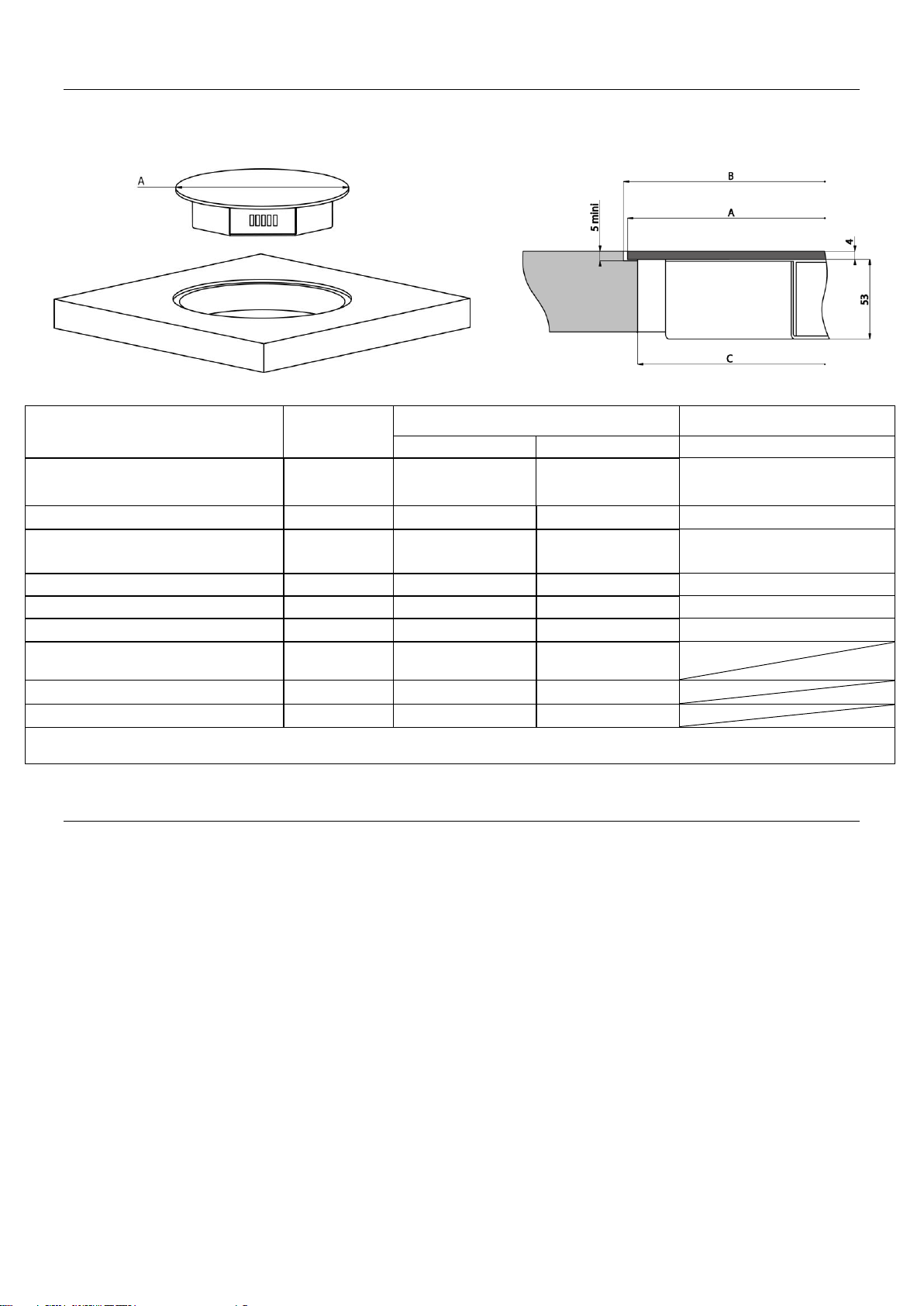
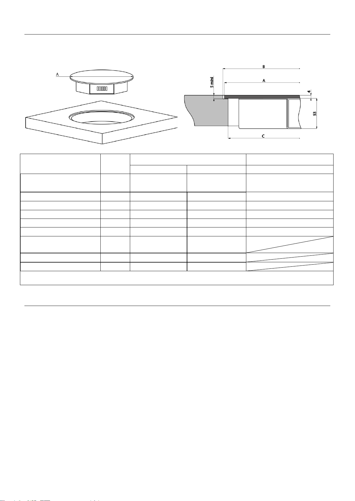
Afmeting
Kookzone
Bedieningspaneel
5 7 C
Referentie
1790-002
1790-003
1790-001 / 1791-001
Afmeting van het glas
A
270mm
300mm
326 x 160 – R80
Diameter van de uitsnijding
voor vlakinbouw
B
274mm
304mm
330 x 164 – R82
Dikte van het glas
4mm
4mm
4mm
Afmeting van de uitsnijding
C
254mm
284mm
314 x 150 – R75
Totale hoogte
57mm
57mm
35mm
Diameter van de inductie
160mm
200mm
Basisvermogen
1100W
2300W
Boostervermogen
2500W
3000W
Afmetingen van de technische box 1790-004 / 1791-004: 270x210x48
Toestellen en afmetingen van de installatie
INSTALLATIEAANWIJZINGEN
Installatie
Verwijder alle verpakkingen.
De installatie en de elektrische aansluiting van het apparaat dienen aan een erkende
vakman toevertrouwd te worden. De fabrikant kan niet verantwoordelijke gesteld worden
voor eventuele schade voortkomend uit een foutieve inbouw of aansluiting.
Het apparaat mag enkel gebruikt worden wanneer het gemonteerd en geïnstalleerd is in
een meubel met een gehomologeerd en aangepast werkvlak.
Het is enkel bestemd voor gewoon huishoudelijk gebruik (bereiding van voedingsmidde-
len) met uitsluiting van alle ander huishoudelijk, commercieel of industrieel gebruik.
Verwijder alle etiketten en zelfklevers van het vitrokeramisch glas.
Het apparaat niet ombouwen of wijzigen.
De kookplaat dient niet als ondergrond of werkvlak.
De veiligheid wordt enkel verzekerd wanneer het apparaat volgens de vereiste voor-
schriften op een aardleiding is aangesloten.
Gebruik geen verlengkabel voor de aansluiting op het elektrische net.
Het apparaat mag niet gebruikt worden boven een vaatwasmachine of een droogkast, de
vrijgekomen damp kan de elektronische apparatuur beschadigen.
Page 4
4
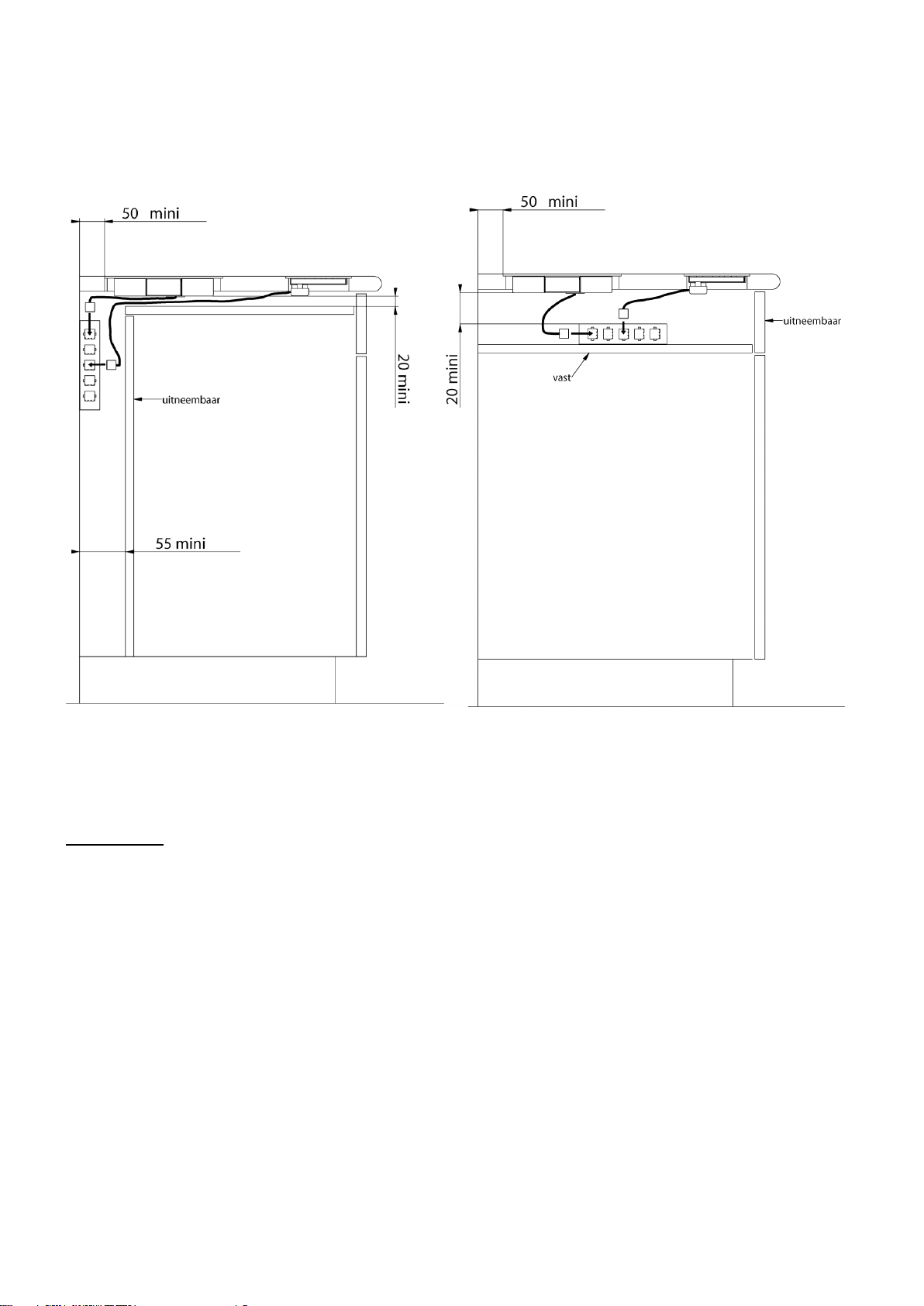
Verluchting van de inductiemodule
Opgelet: het afkoelingssysteem vereist een zekere ruimte voor ventilatie.
Om voldoende verluchting voor het elektronische gedeelte van de kookzone onder de
opening te bekomen, is er een zekere afstand nodig.
Aanwijzingen voor het plaatsen
Het plaatsen en de aansluiting mogen enkel uitgevoerd worden door een bevoegde specialist.
De gebruiker moet erop toezien dat de geldende normen in zijn woning gerespecteerd worden.
Installatie :
De bekleding van de werkbladen moet uit warmtebestendig materiaal (100°C) bestaan
De strips aan de muurranden moeten hittebestendig zijn
De kookplaat is een apparaat toebehorend aan de beschermingsklasse « Y ». Ingebouw
mag er zich een hoge kastwand of een muur aan een zijde en aan de achterzijde bevinden. Aan de andere zijde mag geen enkel meubel of apparaat hoger zijn dan het
kookvlak.
De afstand tussen de kookzones en de muur moet minstens 50mm zijn.
De materialen van het werkblad kunnen uitzetten bij contact met vochtigheid. Om de uit-
snijding te beschermen, een vernis of speciale lijm aanbrengen.
De veiligheidsafstand tussen de kookzones en de dampkap die erboven geplaatst is
moet de aanwijzingen van de fabrikant van de dampkap respecteren. In afwezigheid van
aanwijzingen een minimumafstand van 760 mm respecteren.
De aansluitingskabels mogen na inbouw aan geen enkele mechanische hinder onder-
worpen worden, zoals bijvoorbeeld een lade.
Page 5
5
Nota : - Het is ten strengste verboden op de kabel van de zones te verkorten of te verlen-
gen.
- Wij zijn niet verantwoordelijk indien de verbindingen niet warden gemaakt zoals
aangeduid en/of indien de veiligheidswaarschuwingen niet warden nageleefd.
AASLUITING VAN DE VERSCHILLENDE ELEMENTEN
De installatie en aansluiting van dit toestel dient te gebeuren door een professional die perfect
op de hoogte is van de geldende regels.
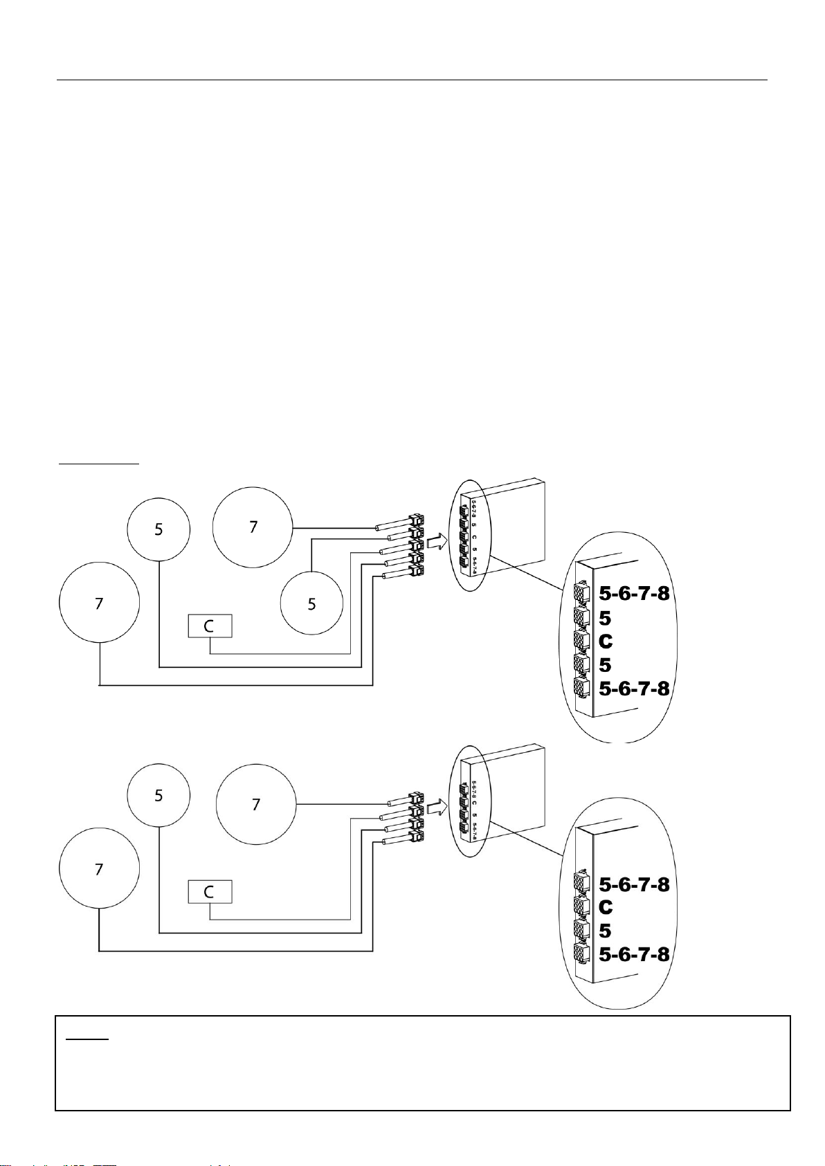
Verbinding van de kookzones
De verbinding van elke kookzone is aangeduid met een sticker met een getal van 5 tot 8, overeenstemmend met:
5: Zone 1100 W / diameter glas 270mm
7: Zone 2300 W / diameter glas 300mm
Het bedieningspaneel wordt aangeduid door “C” op de verbinding
Op de technische box staan de volgende vermeldingen bij de aansluitingen: 5-6-7-8-C.
Verbind het bedieningspaneel met “C” op de technische box.
Verbind de zones met het overeenstemmende cijfer op de box.
Om de verbindingen makkelijk te maken, begint u best met het hoogste
getal.
Voorbeeld:
Page 6
6
P
CONFIGURATIEPROCEDURE VOOR DE
INWERKINGSTELLING
De plaat moet worden geconfigureerd volgens onderstaande procedure :
I) Opgelet: u mag niet meteen kookpotten plaatsen op de inductieplaat.
II) Koppel de plaat los van het stroomnet: schakel zekering of hoofdschakelaar uit.
III) Verbind de plaat weer op het stroomnet: schakel de zekering of de hoofdschakelaar
terug in.
IV) Procedure:
* Onderstaande procedure dient binnen de 2 minuten uitgevoerd te worden.
* Neem een kookpot met ferromagnetische bodem met een minimale diameter van
16 cm.
* druk niet op [ 0/I ]
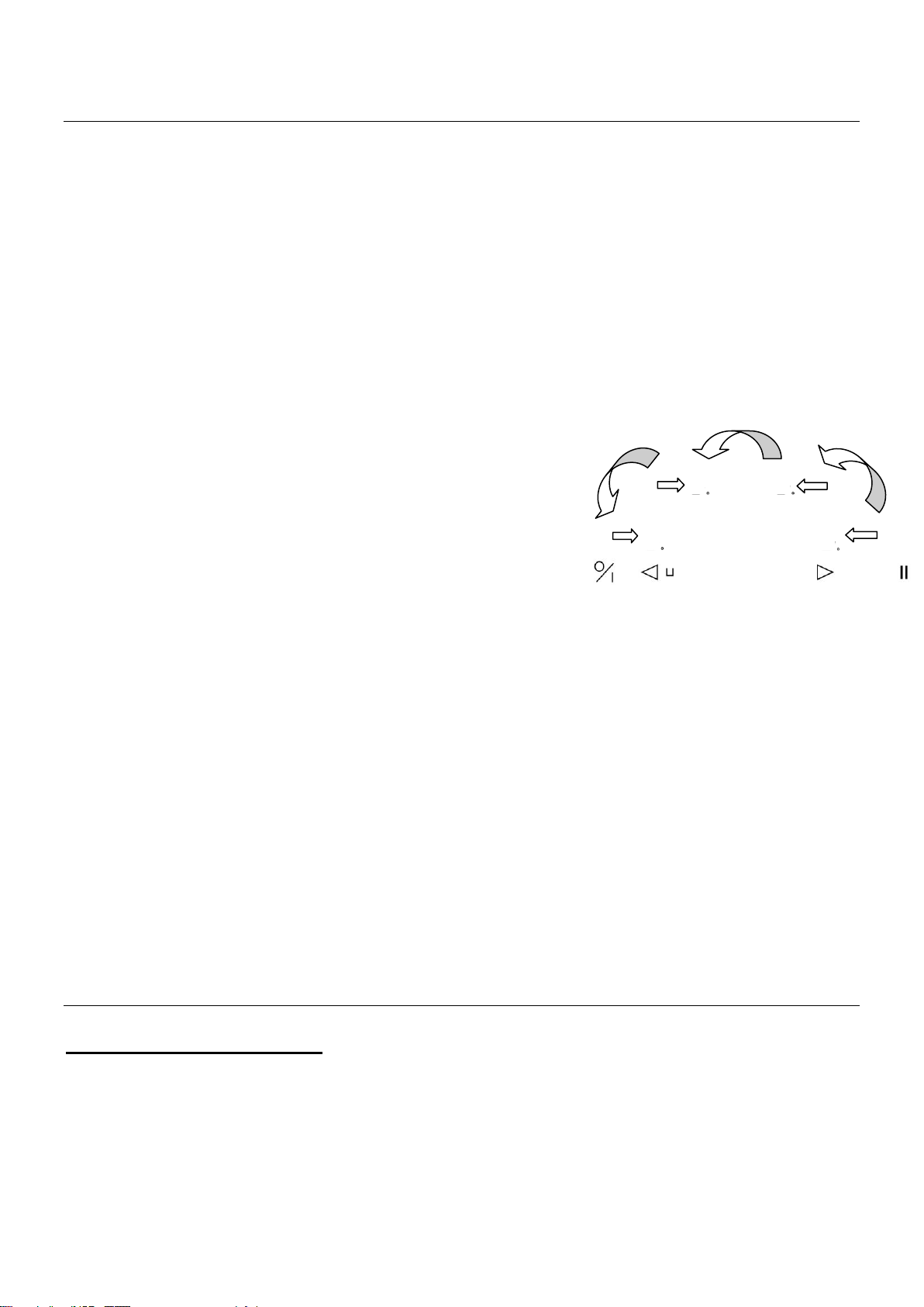
V) Eerst moet de bestaande configuratie worden geannuleerd
1) Druk op toets [ P ] en houd deze toets ingedrukt.
2) Iedere zone dient in de juiste volgorde geselecteerd te worden binnen de 2 seconden. (zie
afbeelding)
3) druk met de vinger van de andere hand op [.]
via de beweging (a->b->c->d)
Een dubbele piep duidt op een foute handeling.
Herhaal in dat geval de bewerking vanaf stap 1.
4) Laat de toetsen los.
5) Houd [ 0/I ] ingedrukt tot de knipperende [ E ] verschijnt.
6) Wacht tot de [ E ] ophouden met knipperen.
7) De [ E ] veranderen vervolgens automatisch in [ C ]. De configuratie is geannuleerd.
VI) Hoe kunt u de plaat opnieuw configureren?
1) Neem een ferromagnetisch kookpot met een diameter van minstens 16 cm.
2) Selecteer de kookzone door op de bijbehorende [ C ] te drukken.
3) Plaats de kookpot op de zone die u wilt configureren.
4) Wacht tot [ C ] verandert in [ - ]. De kookzone is geconfigureerd.
5) Ga op dezelfde manier te werk voor alle kookzones die [ C ] weergeven.
6) De kookzones zijn geconfigureerd als alle zones zijn gedetecteerd en er niets
meer wordt weergegeven.
Gebruik slechts een recipiënt om de configuratie uit te voeren.
Plaats tijdens de configuratie nooit meerdere recipiënten op de kookpunten.
KLEINE PROBLEMEN VERHELPEN
Het symbool [ E4] verschijnt:
Stel de kookplaat opnieuw in
Indien het symbool blijft verschijnen, gelieve de Dienst na Verkoop te contacteren.
Page 7
7
Land
Netwerk
Aansluiting
Kabeldiameter
Kabel
Bescher-
mingskaliber
GB-NL-FR
230V~1F+N 50Hz
1 Fase + N
3 x 2.5 mm²
H 05 VV - F
H 05 RR - F
25 A *
400V~2F+N 50Hz
2 Fases + N
4 x 1.5 mm²
H 05 VV - F
H 05 RR - F
16 A *
Netwerk
Aansluiting
Aansluitsnoer
Aansluitsnoer
Kaliber automa-
ten
230 V~ 50/60 Hz
1 fase +N
3 x 2,5 mm2
H 05 VV - F
H 05 RR - F
25 A *
400 V~ 50/60Hz
2 fasen + N
4 x 1,5 mm2
H 05 VV - F
H 05 RR - F
16 A *
230 V~ 50/60 Hz
2 fasen
3 x 2,5 mm2
H 05 VV - F
H 05 RR - F
25 A *
230 V~ 50/60 Hz
3 fasen
4 x 1,5 mm2
H 05 VV - F
H 05 RR - F
16 A *
We kunnen niet verantwoordelijk gesteld worden voor ongevallen voortkomend uit een
slechte aansluiting of ongevallen die gebeuren door toestellen zonder of met een defecte aarding.
ELEKTRISCHE AANSLUITING
De installatie en de aansluiting op het elektrische net mag enkel toevertrouwd worden
aan een vakman (elektricien) die op hoogte is van de voorgeschreven normen.
Na het monteren moeten de stukken die onder spanning staan beschermd blijven.
De nodige aansluitgegevens staan op het kenplaatje et het aansluitingsplaatje aan de
onderkant van het apparaat.
Het apparaat dient door middel van een meerpolige stroomverbreker van het net ge-
scheiden te zijn. Staat deze open (niet aangesloten), dans moet de contactopening minstens 3mm bedragen.
Het elektrische circuit dient van het net gescheiden te zijn door middel van de nodige
voorzieningen, zoals bijvoorbeeld beveiligingsschakelaars, zekeringen, differentiële
schakelaars en contacten.
*berekend met de coëfficiënt van gelijktijdigheid volgens de standaard EN 60 335-2-6/1990
Opgepast !
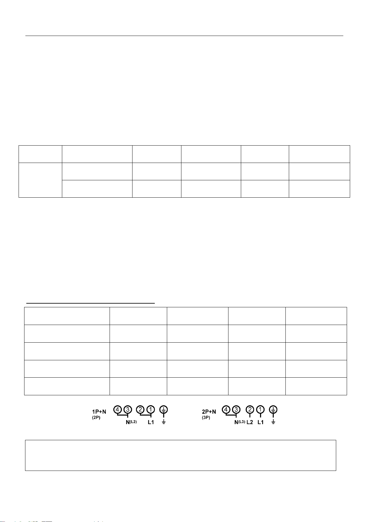
- Dit apparaat is voorzien voor een aansluiting op een netspanning van 230V~ 50 HZ
- Verbind steeds de aarding.
- Respecteer het aansluitingsschema.
- De aansluitingsdoos bevindt zich onder de kookplaat. Om het deksel te openen, gebruik een
schroevendraaier van gemiddelde grootte. Plaats hem in de 2 gleuven die zich voor de 2 pijlen
bevinden.
Belangrijk
De aansluitdraden van de kookzones mogen in geen geval worden verlengd of ingekort.
AANSLUITING VAN DE KOOKPLAAT:
* berekend met de coëfficiënt van gelijktijdigheid volgens de standaard EN 60 335-2-6/1990
Let op ! De draden goed doorsteken en de schroeven goed aanspannen.
Page 8

8
SOMMAIRE
DESCRIPTION ............................................................................................................................ 9
APPAREILS ET DIMENSION D'INSTALLATION .................................................................................... 9
INSTRUCTIONS D’INSTALLATION ........................................................................................... 9
INSTALLATION ............................................................................................................................. 9
VENTILATION DES MODULES D’INDUCTION.................................................................................... 10
INDICATIONS D'ASSEMBLAGE ...................................................................................................... 10
RACCORDEMENT DES DIFFERENTES PARTIES ................................................................. 11
RACCORDEMENT DES ZONES DE CUISSON ................................................................................... 11
PROCEDURE DE CONFIGURATION ................................ ....................................................... 12
QUE FAIRE EN CAS DE PROBLEME ...................................................................................... 12
CONNEXION ELECTRIQUE ..................................................................................................... 13
Page 9
9
DESCRIPTION
Cotes
Zone de cuisson
Bandeau de commande
5 7
Référence
1790-002
1790-003
1790-001 / 1791-001
Dimension du verre
A
270mm
300mm
326 x 160 – R80
Diamètre de la gorge
B
274mm
304mm
330 x 164 – R82
Epaisseur du verre
4mm
4mm
4mm
Dimension de découpe
C
254mm
284mm
314 x 150 – R75
Hauteur total
57mm
57mm
35mm
Diamètre de
l’inducteur
160mm
200mm
Puissance initiale
1100W
2300W
Puissance du Booster
2500W
3000W
Dimensions du boitier 1790-004 /1791-001 : 270x210x48
Appareils et dimension d'installation
INSTRUCTIONS D’INSTALLATION
Installation
Retirez toutes les parties de l’emballage.
L’installation et le branchement électrique de l’appareil sont à confier à des spécialistes
agrées. Le fabricant ne peut être tenu responsable des dommages résultant d’une erreur
d’encastrement ou de raccordement.
L’appareil ne doit être utilisé que s’il est monté et installé dans un meuble et un plan de
travail homologué et adapté.
Son utilisation est uniquement destinée à l’usage domestique habituel (préparation des
aliments), à l’exclusion de toute autre utilisation domestique, commerciale ou industrielle.
Enlevez toutes les étiquettes et autocollants du verre vitrocéramique.
Ne pas transformer ou modifier l’appareil.
Les zones de cuisson et la commande ne doivent pas servir de support ou de plan de
travail.
La sécurité n’est assurée que si l’appareil est raccordé à une terre de protection con-
forme aux prescriptions en vigueur.
Pour le raccordement au réseau électrique n’utilisez pas de rallonge.
L’appareil ne doit pas être utilisé au-dessus d’un lave-vaisselle ou d’un sèche-linge : les
vapeurs d’eau dégagées pourraient détériorer l’électronique.
Page 10

10
Ventilation des modules d’induction
Important : le système de refroidissement nécessite un certain espace d’aération.
Pour obtenir une aération suffisante de l'électronique dans le champ de cuisson, sous la
cavité, une certaine distance est nécessaire pour l’aération.
Indications d'assemblage
L'assemblage et le raccordement ne peuvent être entrepris que par un spécialiste autorisé.
L'utilisateur doit veiller à ce que les normes étant en vigueur dans son domicile soient observées.
Installation
Les placages et revêtements des plans de travail doivent être réalisés en matériaux ré-
sistant à la chaleur (100°C)
Les baguettes de bord murales doivent être thermo résistantes
La table de cuisson est un appareil qui appartient à la classe de protection « Y ». Lors de
son encastrement, une paroi d’armoire haute ou un mur peut se trouver sur l’un des côtés et sur la face arrière. Mais de l’autre côté, aucun meuble ni aucun appareil ne
doit être plus haut que le plan de cuisson
La distance entre les zones de cuisson et le mur doit être au minimum de 50mm.
Les matériaux des plans de travail peuvent gonfler au contact de l’humidité. Pour proté-
ger le chant de la découpe, appliquer un vernis ou une colle spéciale.
L’écart de sécurité entre les zones de cuisson et la hotte aspirante placée au-dessus
d’elle doit respecter les indications du fabricant de hottes. En cas d’absence
d’instructions respecter une distance minimum de 760mm
Les câbles de raccordement ne doivent être soumis, après encastrement, à aucune con-
trainte mécanique, comme par exemple du fait d’un tiroir
Page 11

11
Nota : - Il est strictement interdit de rallonger ou raccourcir les fils des zones de cuisson.
- Nous ne prenons aucune responsabilité en cas de non respect des branchements
indiqués et des avertissements de sécurité.
RACCORDEMENT DES DIFFÉRENTES PARTIES
L'installation et le raccordement de cet appareil ne peuvent être entrepris que par un spécialiste
autorisé. L'installateur doit veiller à ce que les normes en vigueur dans son pays soient observées.
Raccordement des zones de cuisson
Chaque connecteur des zones de cuisson, est repéré par un autocollant avec la numérotation
de 5 à 8 correspond à :
5: Zone de 1100 W / Diamètre du verre 270mm
7: Zone de 2300 W / Diamètre du verre 300mm
Le bandeau de commande électronique est repéré par un « C » sur le connec-
teur.
Sur le boitier, à proximité des connecteurs est apposé un autocollant avec 5-6-7-8-C.
Raccorder le connecteur du bandeau de commande sur le boitier au niveau
du C.
Raccorder les connecteurs des zones de cuisson sur le boitier en respectant la correspondance des nombres.
Pour faciliter le branchement, commencer par raccorder les nombres les
plus hauts.
Exemple :
Page 12

12
P
PROCEDURE DE CONFIGURATION
La table doit être configurée suivant la procédure ci-dessous :
I) Attention : au départ ne pas mettre de récipients sur la table à induction.
II) Débrancher la table du réseau électrique : enlever le fusible ou couper le disjoncteur.
III) Rebrancher la table au réseau électrique : remettre le fusible ou rebrancher le disjoncteur.
IV) Procédure :
* prendreun récipient à fond ferromagnétique de diamètre 16 cm minimum.
* démarrer en moins de 2 minutes après branchement au réseau électrique.
* ne pas appuyer sur [ O/I ]
V) Il faut d'abord annuler la configuration existante
1) Appuyer sur la touche [ P ] et rester appuyé.
2) Sur chaque afficheur apparait un [ . ]
3) Avec un doigt de l'autre main appuyer
successivement et rapidement (en moins
de 2s) sur les [ . ].En partant de la zone
Avant-Droite et en tournant dans le sens
inverse des aiguilles d'une montre
(a -> b -> c -> d). Un double "bip" signifie une
erreur de manipulation. Dans ce cas, refaire
l'opération depuis l'étape n° 1.
4) Oter les doigts des touches et réappuyer sur la touche [ 0/I ] pendant quelques
secondes jusqu'à ce que les [ E ] clignotants apparaissent.
5) Attendre que les [ E ] deviennent fixes.
6) Les [ E ] se transforment ensuite automatiquement en [ C ].
La configuration est annulée.
VI) Comment reconfigurer la table ?
1) Prendre un récipient ferro-magnétique de diamètre 16cm minimum.
2) Sélection la zone de cuisson en appuyant sur le [ C ] correspondant.
3) Poser le récipient sur la zone à configurer.
4) Attendre jusqu'à ce que [ C ] se transforme en [ - ]. La zone de cuisson est configurée.
5) Procéder de la même manière pour toutes les zones de cuisson qui affichent [ C ].
6) Les zones de cuisson sont configurées lorsque toutes les zones auront été détectées
et que plus rien n'est affiché.
Nota : …..N'utilisez qu'un seul récipient pour effectuer la configuration.
Ne jamais poser plusieurs récipients sur les foyers pendant la configuration.
QUE FAIRE EN CAS DE PROBLEME
Le symbole [ E4 ] apparaît :
Reconfigurer la table
Si l’affichage persiste, appelez le Service Après-vente.
Page 13

13
Réseau
Raccordement
Section cordon
Cordon
d’alimentation
Calibre de disjoncteur
230V~ 50/60Hz
1 Phase + N
3 x 2.5 mm²
H 05 VV - F
H 05 RR - F
25 A *
400V~ 50/60Hz
2 Phases + N
4 x 1.5 mm²
H 05 VV - F
H 05 RR - F
16 A *
230V~ 50/60Hz
2 Phases
3 x 2.5 mm²
H 05 VV - F
H 05 RR - F
25 A *
230V~ 50/60Hz
3 Phases
4 x 1.5 mm²
H 05 VV - F
H 05 RR - F
16 A *
CONNEXION ÉLECTRIQUE
L’installation de cet appareil et son branchement au réseau électrique ne doit être confié
qu’à un électricien parfaitement au fait des prescriptions normatives.
La protection contre les pièces sous tension doit être assurée après le montage.
Les données de raccordement nécessaires se trouvent sur la plaque signalétique et la
plaque de branchement placées sous l’appareil.
Cet appareil doit être séparé du secteur par un dispositif de sectionnement omnipôles.
Lorsque celui-ci est ouvert (déclenché), un écartement de 3mm doit être assuré.
Le circuit électrique doit être séparé du réseau par des dispositifs appropriés, par
exemple les disjoncteurs, les fusibles, les disjoncteurs différentiels et les contacteurs.
BRANCHEMENT DE LA TABLE
Pour les différents branchements utilisez les pontets en laiton qui se trouvent dans le boîtier de
branchement.
Attention !
Cet appareil n’est conçu que pour une alimentation en 230 V~ 50 / 60 Hz.
Raccordez toujours le fil de terre de protection.
Respectez le schéma de raccordement.
Le boîtier de raccordement se situe sous la plaque de cuisson. Pour ouvrir le capot, servezvous d’un tournevis moyen. Placez le dans les 2 fentes situées à l’avant des 2 flèches.
Branchement de la table:
* calculé avec le coefficient de simultanéité suivant standard EN 60 335-2-6/1990
Attention ! Veillez à bien engager les fils et à bien serrer les vis.
Notre responsabilité ne saurait être engagée pour tout incident résultant d’un mauvais
branchement, ou qui pourrait survenir à l’usage d’un appareil non relié à la terre ou équi-
pé d’une terre défectueuse.
Page 14

14
INHALTSVERZEICHNIS
BESCHREIBUNG ...................................................................................................................... 15
GERÄTE UND EINBAUMASSE ...................................................................................................... 15
EINBAU DER EINZELKOCHZONEN ........................................................................................ 15
EINBAU .................................................................................................................................... 15
BELÜFTUNG DES INDUKTIONSMODULS......................................................................................... 16
MONTAGEHINWEISE .................................................................................................................. 16
VERBINDUNG DER VERSCHIEDENEN TEILE ....................................................................... 16
VERBINDUNG DER KOCHZONEN ................................................................................................ .. 17
KONFIGURATION ANORDNUNG ............................................................................................ 18
ELEKTROANSCHLUSS ............................................................................................................ 19
Page 15

15
BESCHREIBUNG
Abmessungen
Kochzone
Bedienung
5
7
C
Referenz
1790-002
1790-003
1790-001 / 1791-001
Durchmesser des Glases
A
270mm
300mm
326 x 160 – R80
Falzdurchmesser
B
274mm
304mm
330 x 164 – R82
Dicke des Glases
4mm
4mm
4mm
Ausschnittdurchmesser
C
254mm
284mm
314 x 150 – R75
Gesamtzahlhöhe
57mm
57mm
35mm
Durchmesser des
Induktors
160mm
200mm
Leistung
1100W
2300W
Booster Leistung
2500W
3000W
Abmassen vom Generator 1790-004 /1791-004 : 270x210x48
Geräte und Einbaumasse
EINBAU DER EINZELKOCHZONEN
Einbau
Alle Teile auspacken.
Das Gerät darf nur von einem Elektrofachmann eingebaut und angeschlossen werden.
Der Hersteller kann nicht verantwortlich gemacht werden für Schäden, die durch Fehler
beim einbauen oder anschließen verursacht werden.
Benützen Sie das Gerät nur im eingebauten Zustand.
Dieses Gerät darf nur für das haushaltübliche Kochen und Braten von Speisen
verwendet werden und ist nicht für gewerbliche Zwecke bestimmt.
Alle Etiketten und Aufkleber des Glases wegnehmen.
Die Sicherheit ist nur gewährleistet, wenn das Gerät mit einem Schutzleiter verbunden
ist, der den gültigen Vorschriften entspricht.
Der Anschluss der Gerätes an das Elektronetz darf nicht über ein Verlängerungskabel
erfolgen.
Das Gerät darf nicht über einem Geschirrspüler oder einem Wassertrockner benutzt
werden: die freigesetzten Wasserdämpfe könnten die Elektronik beschädigen.
Page 16

16
Belüftung des Induktionsmoduls
Wichtig: das Kühlungssystem braucht einen gewissen Belüftungsraum.
Um eine ausreichende Belüftung der Elektronik im Kochfeld zu erzielen, ist unter der
Mulde ein gewisser Abstand für Luftraum notwendig.
Montagehinweise
Montage und Anschluss dürfen nur durch einen Fachmann vorgenommen werden.
Der Benutzer muss darauf achten dass die in seinem Wohnsitz geltenden Normen eingehalten
werden.
Einbau :
Furniere unter der Arbeitsplatte müssen mit hitzbeständigem Kleber (100 °C) verarbeitet
sein.
Die Wandabschlussleisten müssen hitzbeständig sein
Dieses Gerät entspricht bezüglich des Schutzes gegen Feuergefahr dem Typ Y. Nur
Geräte dieses Typs dürfen einseitig an nebenstehende Hochschränke oder Wände
eingebaut werden.
Der Abstand zum Ausschnitt einer Mauer und/oder einem Möbelstück muss mindestens
50 mm betragen.
Die Schnittflächen sollen mit speziellem Lack, Silikonkautschuk oder Giessharz
versiegelt werden, um ein aufquellen durch Feuchtigkeit zu verhindern.
Zwischen dem Gerät und einer Dunstabzugshaube muss der vom Hersteller
angegebene Sicherheitsabstand eingehalten werden. Bei fehlenden Angaben muss
dieser Abstand mindestens 760 mm sein.
Es muss sichergestellt werden, dass das Anschlusskabel des Kochfeldes nach dem
Einbau keiner mechanischen Belastung, z.B. durch Schublade, ausgesetzt ist.
VERBINDUNG DER VERSCHIEDENEN TEILE
Page 17

17
Bemerkung : -Jede Einrichtung außer denen, die auf den vorhergehenden Seiten enthalten
sind, kann das Induktionsmodul ernst beschädigen.
- Es ist strikt verboten, den Kabel der Kochzonen zu verlängern oder zu kürzen
-Wir lehnen jede Verantwortung ab bei Nichtbeachtung der angegebenen
Verkabelung und der Sicherheitswarnungen.
Einbau und Anschluss dieses Geräts dürfen nur durch einen autorisierten Fachmann
vorgenommen werden. Der Benutzer muss darauf achten, dass die in seinem Wohnsitz
geltenden Normen eingehalten werden.
Verbindung der Kochzonen
Jede Verbindung der Kochzonen wird durch einen Aufkleber mit der Nummerierung von 1 bis 3
entdeckt. Sie entspricht:
5: Zone von 1100 W / Durchmesser des Glases 270mm
7: Zone von 2300 W / Durchmesser des Glases 300mm
Der elektronische Auftragsfries wird durch ein “C“ auf der Verbindung ent-
deckt.
An dem Induktionsmodul in der Nähe von den Anschluss-Steckern ist ein Aufkleber mit den
Buchstaben: 5-6-7-8-C.
Verbinden vom Bedienungsteil an die Stelle “C“ vom Generator.
Verbinden vom den Kochzonen an die entsprechende Nummer vom Generator.
Um diese Verbindung zuvereinfachen beginnen Sie mit dem höchsten
Korzonen Nummer.
Beispiel:
Page 18

18
KONFIGURATION ANORDNUNG
P
Das Kochfeld muss neu konfiguriert werden. Bitte folgen Sie nachstehender Hinweise:
I) Wichtig : entfernen Sie alle Töpfe von Ihrem Kochfeld
II) Das Kochfeld muss zuerst vom Stromnetz getrennt werden: nehmen Sie den An-
schlusskabel weg oder schalten Sie die Sicherung am Schalttafel ab.
III) Schalten Sie den Strom wieder ein
IV) Verfahren :
* nehmen Sie einen Topf mit magnetischem Boden (Durchmesser > 16 cm)
* verwenden Sie nicht den Hauptschalter
* starten Sie die Programmierung spätestens 2 Minuten nach dem Wiedereinschalten
V) Phase 1: löschen der existierenden Konfiguration
1) Drücken Sie auf die Taste [ P ] und halten Sie
diese gedrückt
2) In der Anzeige erscheint [ . ]
3) Mit Ihrem anderen Finger drücken Sie
nacheinander, entegegen dem Uhrzeigersinn,
die Anzeigen [ . ] (vgl Bezeichnung)
Ein doppelter “Beep“ soll heissen, dass ein
Fehler Aufgetreten ist. In diesem Fall,
starten Sie erneut vom Punkt 1.
4) Lassen die Taste los. Dann drücken Sie wieder auf die Taste [ 0/I ], bis dass blinkende [ E ] Symbole angezeigt werden.
5) Erwarten bis die [ E ] fix bleiben
6) [ E ] werden dann automatisch [ C ]-Symbole. Das Löschprozess ist erledigt.
Bemerkung : bei Induktionskochfelder mit 3 Kochzonen : hinten rechts anfangen
(b) (die Kochzone vorne rechts gib es nicht).
VI) Phase 2 : Neukonfiguration des Kochfeldes
1) Nehmen Sie einen Topf mit magnetischem Boden (Durchmesser > 16 cm)
2) Wählen Sie eine Kochzone-Bedienung aus beim drücken auf dem [C]-Symbol.
3) Stellen Sie den Topf auf der entsprechenden Kochzone.
4) Warten bis [ C ] sich in [ - ] umwandelt. Die Kochzone ist konfiguriert.
5) Wiederholen Sie diesen Vorgang für jede Kochzone.
6) Die Kochzonen sind konfiguriert, sobald nichts mehr angezeigt wird.
Verwenden Sie den gleichen Topf um die gesamte Konfiguration durchzuführen.
Während der Konfiguration dürfen keine weiteren Töpfe auf der Mulde liegen.
In der Anzeige erscheint [ E4 ]:
Die mulde neu konfigurieren
Wenn [ E4 ] immer noch erscheint, rufen Sie den Kundendienst an.
Page 19

19
Netz
Anschluss ( * )
Anschlusskabel
Anschlusskabel
Schutzschalter
230V~ 50/60Hz
1 Faser + N
3 x 2,5 mm²
H 05 VV - F
H 05 RR - F
25 A *
400V~ 50/60Hz
2 Faser + N
4 x 1.5 mm²
H 05 VV - F
H 05 RR - F
16 A *
230V~ 50/60Hz
2 Faser
3 x 2,5 mm²
H 05 VV - F
H 05 RR - F
25 A *
230V~ 50/60Hz
3 Faser
4 x 1,5 mm²
H 05 VV - F
H 05 RR - F
16 A *
Wir sind nicht verantwortlich für Zwischenfälle die durch falschen Anschluss, oder nicht vorhandenen oder unrichtigem Erdungsanschluss entstehen.
ELEKTROANSCHLUSS
Zum Anschluss des Gerätes an das Elektronetz beauftragen Sie einen Elektrofachmann,
der die landesüblichen Vorschriften der örtlichen Elektroversorgungsunternehmen genau
kennt und sorgfältig beachtet.
Der Berührungsschutz isolierter Teile muss nach der Montage sichergestellt sein.
Ob die erforderlichen Anschlussdaten mit denen des Netzes übereinstimmen finden Sie
auf dem Typenschild.
Das Gerät muss durch Trenneinrichtungen allpolig vom Netz abgeschaltet werden kön-
nen. Im abgeschalteten Zustand muss ein Kontaktabstand von 3 mm vorhanden sein.
Als geeignete Trennvorrichtungen gelten LS-Schalter, Sicherungen und Schütze
Die Installation muss durch Sicherungen geschützt sein. Elektrische Kabel müssen per-
fekt durch das Einbauen gedeckt sein.
Achtung !
Der Schutzleiter muss an den gekennzeichneten Anschluss angeschraubt werden.
Netzanschlussleitung
Dieses Gerät ist nur für eine Versorgung von 230 V~ 50/60 Hz ausgelegt.
Schliessen Sie immer, falls vorhanden den Nullleiter (N) mit an.
Beachten Sie das Anschlussschema.
Der Anschlusskasten befindet sich auf der Unterseite des Gerätes. Um das Gehäuse zu öffnen,
benutzen Sie einen Schraubenzieher und schieben Sie ihn in die vorgesehenen Schlitze.
Anschluß des Tisches:
( * ) laut EN 60 335-2-6/1990 Norm
Achtung ! - Die Drähte korrekt hineinstecken und die Schrauben fest anziehen.
Page 20

20
SUMMARY
DESCRIPTION OF THE APPLIANCE ....................................................................................... 21
APPLIANCES AND INSTALLATION DIMENSIONS ............................................................................... 21
MULTIZONES INSTALLATION ................................................................................................ 21
INSTALLATION ........................................................................................................................... 21
VENTILATION ............................................................................................................................ 22
INSTALLATION INSTRUCTIONS ..................................................................................................... 22
CONNEXION OF THE DIFFERENT ELEMENTS ...................................................................... 23
CONNECTION OF COOKING ZONES .............................................................................................. 23
CONFIGURATION PROCEDURE ............................................................................................. 24
WHAT TO DO IN CASE OF A PROBLEM ................................................................................ 24
ELECTRICAL CONNECTION ................................................................................................... 25
Page 21

21
DESCRIPTION OF THE APPLIANCE
Dimension
Heating zone
Finger touch
5 7 C
Reference
1790-002
1790-003
1790-001 / 1791-001
Dimension of
glass
A
270mm
300mm
326 x 160 – R80
Diameter of the
throat
B
274mm
304mm
330 x 164 – R82
Thickness of
glass
4mm
4mm
4mm
Cut-out Dimen-
sion
C
254mm
284mm
314 x 150 – R75
Height total
57mm
57mm
35mm
Diameter of the
inductor
160mm
200mm
Power
1100W
2300W
Booster f
2500W
3000W
Dimensions of the technical box 1790-004 /1791-004 : 270x210x48
Appliances and installation dimensions
MULTIZONES INSTALLATION
Installation
Unpack all the material.
The installation and connection of the appliance have to be done by approved
specialists. The manufacturer can not be held responsible for damage caused by
building-in or connecting errors.
The appliancemust be well-equipped and installed in a kitchen unit and an adapted and
approved work surface.
This domestic appliance is exclusively for the cooking of food, to the exclusion of any
other domestic, commercial or industrial use.
Remove all labels and self-adhesives from the ceramic glass.
Do not transform or modify the appliance.
The cooking zones and the control panel should not be used as support or worktop.
The appliance must be grounded and connected conform to local standards.
Do not use any extension cable to connect it.
The appliance can not be used above a dishwasher or a tumble-dryer: steam may
damage the electronic appliances.
Page 22

22
Ventilation
Important: the cooling system needs some airflow.
Take into account to keep the gap in front of the air inlet of the cooling fan
Installation instructions
The installation comes under the exclusive responsibility of specialists.
The installer is held to respect the legislation and the standards used in his home country.
Fitting - installing:
The piece of furniture or the support in which the hob has to be fitted, as well as the
edges of furniture, the laminate coatings and the glue used to fix them, must be able to
resist temperatures of up to 100 °C.
The mural rods of edge must be heat-resisting.
The hobs are classified as “Y” class for heat protection. Ideally the hob should be
installed with plenty of space on either side. There may be a wall at the rear and tall units
or a wall at one side. On the other side, however, no unit or divider must stand
higher than the hob.
Ensure that there is a distance of 50 mm between the hob and the wall or sides.
Materials which are often used to make worktops expand on contact with water. To
protect the cut out edge, apply a coat of varnish or special sealant. Particular care must
be given to applying the adhesive joint supplied with the hob to prevent any leakage into
the supporting furniture. This gasket guaranties a correct seal when used in conjunction
with smooth work top surfaces.
The safety gap between the hob and the cooker hood placed above must respect the
indications of the hood manufacturer. In case of absence of instructions respect a
distance minimum of 760 mm.
The connection cords should be subjected, after building in, with no mechanical
constraint, such as for example the drawer.
Page 23

23
Nota: - It is strictly forbidden to lengthen or shorten the wire of the cooking zones.
- We do not take any responsibility in cas of not respecting the connections
indicated and the safety warnings.
CONNEXION OF THE DIFFERENT ELEMENTS
The installation of this appliance and the connection to the electrical network should be made by
an electrician perfectly aware, and in respect of the normative regulations
Connection of cooking zones
Each connector of the cooking zones, is located by a sticker with the classification from
5 to 8 corresponds to:
5: Heating zone 1100 W / Glass diameter 270mm
7: Heating zone 2300 W / Glass diameter 300mm
The fingertouch electronic is located by “C” on the connector
On the technical box, near the female connectors are written: 5-6-7-8-C.
Connect the fingertouch on the “C” of the technical box.
Connect the heating zones with the corresponding number on the technical
box.
To connect easily, begging with the biggest number of the heating zone.
Example:
Page 24

24
P
CONFIGURATION PROCEDURE
The table must be configured. Please implement the following steps:
I) Important! Before you start, make sure there is no more pot on the hob
II) Disconnect the appliance from the grid by removing the fuse or turning the circuit breaker off
III) Reconnect the table to the grid
IV) Procedure:
* Take a pot with a ferromagnetic bottom with a minimum diameter of 16 cm
* start the procedure within 2 minutes after reconnecting the hob to the grid
* don’t use the [ O/I ] touch
V) First step: cancel the existing configuration
1) Press the touch [ P ] and hold down
2) The symbol [ . ] will appear on each display
3) With your other hand, press successively and
quickly (less than 2s) on each [ . ] display.
Begin from the front right side and turn contrary
clockwise, as described on the picture (a -> b -> c -> d)).
A double "beep" means an error occurred. If so, start again from item 1).
4) Remove your fingers from the touch control, then push again on touch [ 0/I ] during
few seconds, until blinking [ E ] symbols appear.
5) Wait until [ E ] symbols stop blinking.
6) After few seconds, [ E ] are automatically transformed in [ C ].
The existing setup has been cancelled.
VI) Second step: new setup
Take a pot with a ferromagnetic bottom with a minimum diameter of 16 cm2) Select
a cooking zone by pushing on the corresponding [ C ] display
3) Place the pot on the area to be set
4) Wait until the [ C ] display becomes a [ - ]. The selected cooking zone is now
configured.
5) Follow the same procedure for each cooking zone with a [ C ] display.
6) All the cooking zones are configured once all the displays are turned off.
Note: …..Please use the same pot for the whole procedure.
Never put several pots together on the zones during the setup-process.
WHAT TO DO IN CASE OF A PROBLEM
The symbol [ E4] appears :
Reconfigure the table
If the symbol remains, please contact the After sales service
Page 25

25
Mains
Connection
Supply cord
Supply cord
Circuit braker
230V~ 50/60Hz
1 Phase + N
3 x 2,5 mm²
H 05 VV - F
H 05 RR - F
25 A *
400V~ 50/60Hz
2 Phases + N
4 x 1.5 mm²
H 05 VV - F
H 05 RR - F
16 A *
230V~ 50/60Hz
2 Phases
3 x 2,5 mm²
H 05 VV - F
H 05 RR - F
25 A *
230V~ 50/60Hz
3 Phases
4 x 1,5 mm²
H 05 VV - F
H 05 RR - F
16 A *
ELECTRICAL CONNECTION
The installation of this appliance and the connection to the electrical network should be
entrusted only to an electrician perfectly aware, and in respect of the normative
regulations
Protection against parts under tension must be ensured after the building.
The data of connection necessary are on the stickers place on the hob casing near the
connection box.
The connection to the main must be made using an earthed plug or via an omnipolar
circuit breaking device with a contact opening of at least 3 mm.
The electrical circuit must be separated from the network by adapted devices, for
example: circuit breakers, fuses or contactors.
CONNECTION OF THE HOB
For the various kinds of connection, use the brass bridges which are in the box next the
terminal.
Caution!
This appliance has only to be connected to a network 230 V~ 50/60 Hz.
Connect always the earth wire.
Respect the connection diagram.
The connection box is located underneath at the back of the hob casing. To open the cover use
a medium screwdriver. Place it in the slits and open the cover.
CONNECTION OF THE HOB:
* calculated with the simultaneous factor following the standard EN 60 335-2-6/1990
Caution! Be careful that the cables are correctly engaged and tightened.
We cannot be held responsible for any incident resulting from incorrect connection or
which could arise from the use of an appliance which has not been earthed or has been
equipped with a faulty earth connection.
Page 26

26
Page 27

27
Page 28

13940/3
 Loading...