

Page 1
NV
G
百年品质,值得信赖 —— 您的产品名称
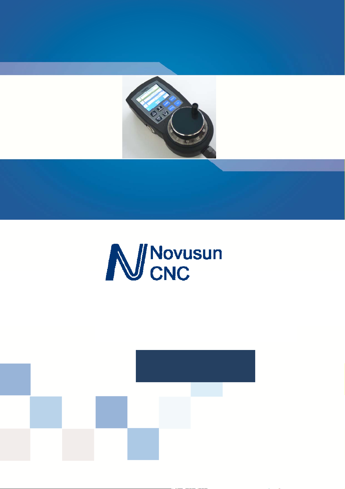
MPG with display
MP
Manual
Page 2

M
Manual of NVMPG
请在这里输入您的公司名称或产品名称
Manual of NVMPG
Chapter 1. Brief Introdution .......................................................................................................................... - 1 -
1.1 Products brief introduction .................................................................................................................... - 1 -
1.2 Specification feature .............................................................................................................................. - 1 -
1.3 Product appearance and dimension ........................................................................................................ - 1 -
1.4 Notice and Waring ................................................................................................................................. - 5 -
Chapter 2. Connection ................................................................................................................................... - 6 -
2.1 Connection interface definition .............................................................................................................. - 6 -
2.2 NVMPG connection............................................................................................................................... - 8 -
Chapter 3. Configuration & Use .................................................................................................................. - 10 -
3.1 Configuration ....................................................................................................................................... - 10 -
3.2 Use ....................................................................................................................................................... - 11 -
Chapter 4. Contract us ................................................................................................................................. - 15 -
Contects
Page 3

Chapter 1 Brief Introdution
Manual of NVMPG
Chapter 1. Brief Introdution
1.1 Products brief introduction
We design a new Manual Pulse Generator named NVMPG. This MPG has a screen,
and 10 buttons. The coordinates and some other parameter are displayed on the screen.
And user can change axis and rate by the buttons. There are also few other functions
e.g. ZERO/ GOTO0/HOME on the buttons.
The encoder of NVMPG is the same as general MPG. but the choice of axis and rate
use USART port instead of general port.
1.2 Specification feature
1) High performance, low prices
2) 2.2' TFT Screen
3) 10 buttons
4) Voltage 5VDC
5) 8 wire control line
6) 6 axis coordinates /RESET/FRO/SRO/SJR/SPINDLE are display on the screen
1.3 Product appearance and dimension
NVBDH+ product appearance pls see picture 1-1 to 1-3.
- 1 -
Page 4
Chapter 1 Brief Introdution
Manual of NVMPG
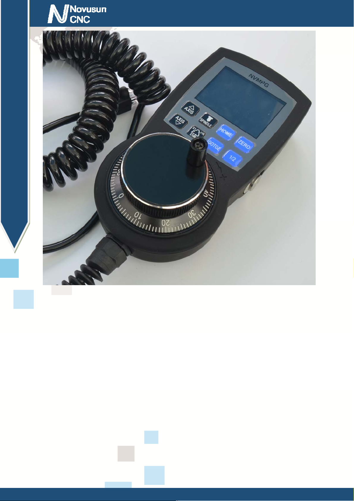
Figure1-1. NVMPG appearance 1
- 2 -
Page 5
Chapter 1 Brief Introdution
Manual of NVMPG
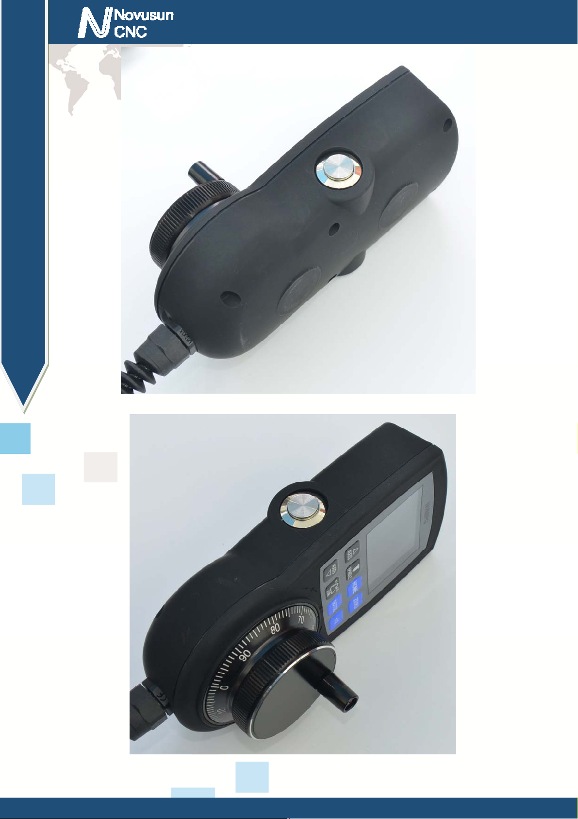
Figure1-2. NVMPG appearance 2
Figure1-3. NVMPG appearance 3
- 3 -
Page 6
Chapter 1 Brief Introdution
Manual of NVMPG
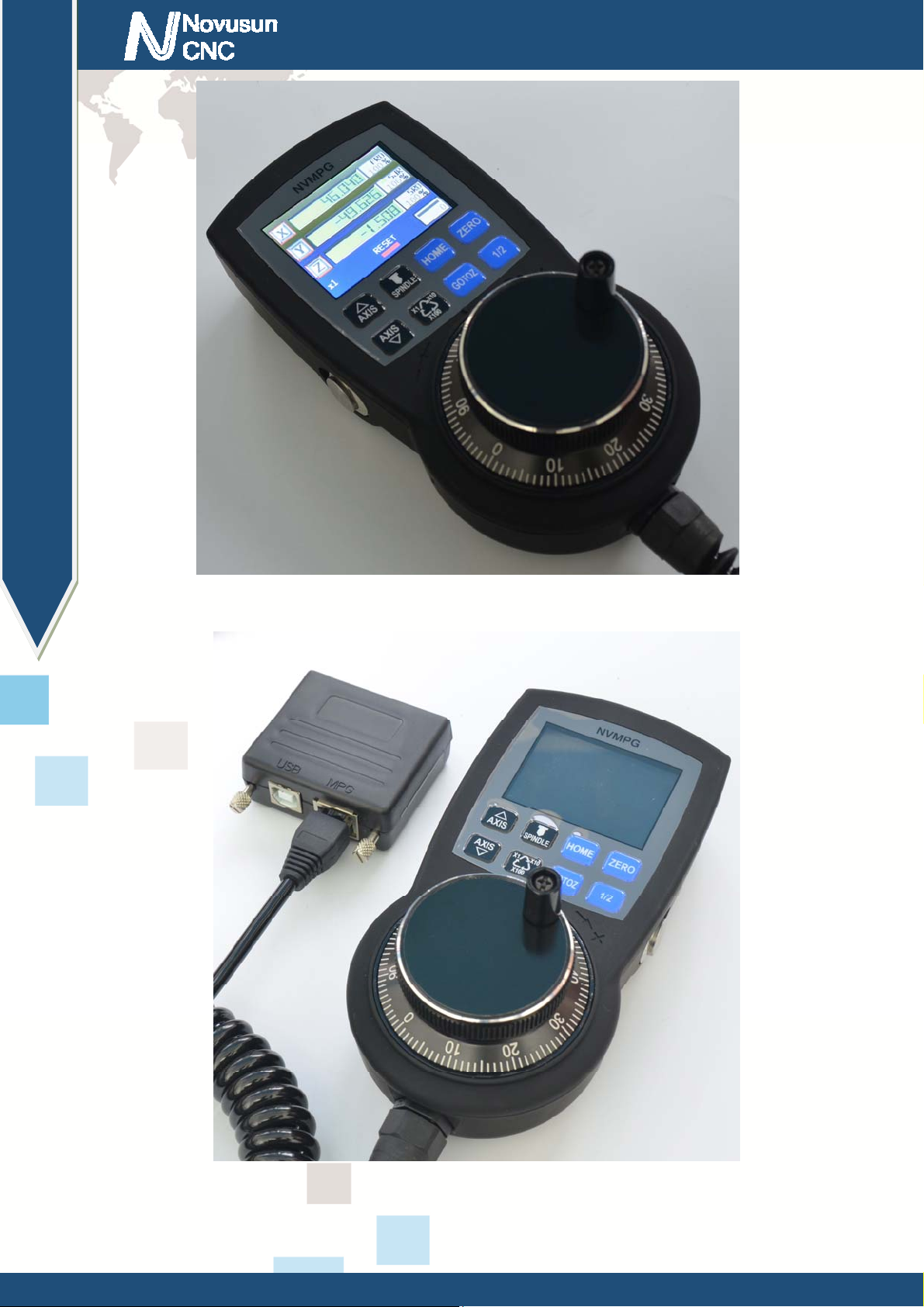
Figure1-4. NVMPG appearance 4 working stat e
Figure1-5. NVMPG connected to NC200
- 4 -
Page 7

Chapter 1 Brief Introdution
Manual of NVMPG
Figure1-6. Size of NVMPG
Product size is 150*75*35mm,as picture 1-6 shows.
1.4 Notice and Waring
Prohibit staying in the rain, it will cause short-circuit..
Pls use proper voltage power supply and motor.
Note the power supply connection. Prohibit reverse connection of power supply
and Hall.
- 5 -
Page 8

Chapter 2 Connection
Chapter 2. Connection
2.1 Connection interface definition
NVMPG has 8 wires connected to CNC system, the definition of NVMPG see as Chart
2-1.
Mark Color Definition Remark
1 RED A- Negative of MPG's A phase
Manual of NVMPG
2 BLUE A+ Positive of MPG's A phase
3 BLACK B- Negative of MPG's B phase
4 GREEN B+ Positive of MPG's B phase
5 WHITE +5V 5V Power wire
6 VIOLET TXD Transmission Port
7 BROWN RXD Receive Port
8 YELLO GND Ground
Chart 2-1 Wiring defi nit io n of NVMPG
There are 2 mode of terminal, which are open wire(see as Figure2-1) and RJ45 port(see as Figure 2-2).
RJ45 port mode is only compatible with NC200. See as Figure 1-5.
- 6 -
Page 9

Chapter 2 Connection
Manual of NVMPG
Figure2-1. Wire mark of NVMPG in open wire mode
Figure2-2. Wire mark of NVMPG in RJ45 port mode
- 7 -
Page 10

Chapter 2 Connection
2.2 NVMPG connection
NVMPG can be connected to NVEM/NVUM and NC200. NVMPG and NVEM
connecting method see as Figure 2-3 and Chart 2-2.
Manual of NVMPG
Figure 2-3 NVMPG connect to NVEM
- 8 -
Page 11

Chapter 2 Connection
NVMPG NVEM
Manual of NVMPG
Definition of NVMPG Definition of NVEM
RED A- WHA-
BLUE A+ WHA+
BLACK B- WHB-
GREEN B+ WHB+
WHITE +5V VDD5
VIOLET TXD TXD
BROWN RXD RXD
YELLO GND GND
Chart 2-2 Connecting method with NVEM
Connection between NVMPG and NC200 is very simply, it's only need to put
NVMPG's RJ45 plug into NC200's RJ45 socket. See as Figure 1-5.
- 9 -
Page 12

Chapter3 Configuration & use
Manual of NVMPG
Chapter 3. Configuration & Use
3.1 Configuration
There are 2 DLL file we provide. If we use standard MPG, we should use
NVEM_F.DLL, or if we use NVMPG, we should use NVEM_UART_F.DLL.
First we need to set MPG to valid, see as Figure 3-1. No need to set other parameter.
Second, if we need to use MPG, we should change Manual operation mode into MPG mode, see as
Figure 3-2.
Figure3-1. Set MPG to valid
- 10 -
Page 13

Chapter3 Configuration & use
Manual of NVMPG
Figure3-2. Set to MPG mode
3.2 Use
See as Figure 3-3,it's definition of NVMPG's screen. Specific description is as follows.
1: Coordinate value of 6 axis
2:Axis identification
3:MPG rate.
4:State of RESET.
5:State and value of Spindle
6:Value of SRO
- 11 -
Page 14

Chapter3 Configuration & use
Manual of NVMPG
7:Value of SJR
8:Value of FRO
Figure3-3. Screen of NVMPG
Figure3-4. buttons of NVMPG
- 12 -
Page 15

Chapter3 Configuration & use
Manual of NVMPG
See as Figure 3-4, there are 10 buttons in NVMPG. Each key has a function. We list the function of these
buttons in Chart 3-1.
No. Mark Definition
1 (LEFT BUTTON) Start/Run G code
2 AXIS↑ Change active axis AXIS++
3 AXIS↓ Change active axis AXIS--
4 SPINDLE START/STOP spindle
5 X1/X10/X100 Change rate of MPG
6 HOME Trigger HOME function of system
7 GOTOZ Trigger go to 0 function of system
8 ZERO Trigger ZERO function of system
9 1/2 Make active axis' coordinate halve
10 (RIGHT BUTTON) RESET/ESTOP
Chart 3-1 Function of keys
Button 1(START) : After loading G code, push this button to run G code.
Button2(AXIS↑):
Button3(AXIS↓): AXIS↑ and AXIS↓ are 2 button for change active axis. Each axis
has a block above the axis label. Active axis' block is yellow, and invalid axis' block is black.
You can notice the color of the block when you change active axis.
Button4(SPINDLE):Open or shut down the spindle.
Button5(X1/X10/X100):Change the rate of MPG, The rate of MPG is displayed on the
screen.
Button6(HOME):Push this button is making machine to find it's Machine zero port. If
we set a active axis, e.g. X, then push this button is going to find X axis' machine zero port. Or if
- 13 -
Page 16

Chapter3 Configuration & use
Manual of NVMPG
we set no active axis, then push this button is going to find all axes' machine zero port.
Button7(GOTOZ):Push is button is making machine to go to workpiece zero port. The
method refer to button 6.
Button8(ZERO):Push this button is making current coordinates to 0. The method refer to
button 6.
Button9(1/2):Push this button is making current coordinates halve. The method refer to
button 6.
Button10(RESET): This button is RESET function.
- 14 -
Page 17

Chapter 4 Contract us
Chapter 4. Contract us
Manual of NVMPG
- 15 -
 Loading...