

NOVUS TxRail 4-20 mA User Manual
TxRail 4-20 mA Transmitter
TEMPERATURE TRANSMITTER - OPERATING MANUAL – V1.2x D
CONFIGURAÇÃO
If the default configuration or the ordered configuration satisfies the
application, then no further configuration is necessary and the
transmitter is ready to be used. If a new setting is desired, this can be
accomplished by the TxConfig and sent to the transmitter through
the TxConfig Interface.
The TxConfig Interface and Software compose the Transmitter
Configuration Kit, which can be purchased separately. The latest
release of this software can be downloaded from our web site. To
install, run the Tx_setup.exe and follow the instructions.
Serial port configuration errors may occur when other software
are sharing the same serial port. Close all serial port
applications prior to using the TxConfig software.
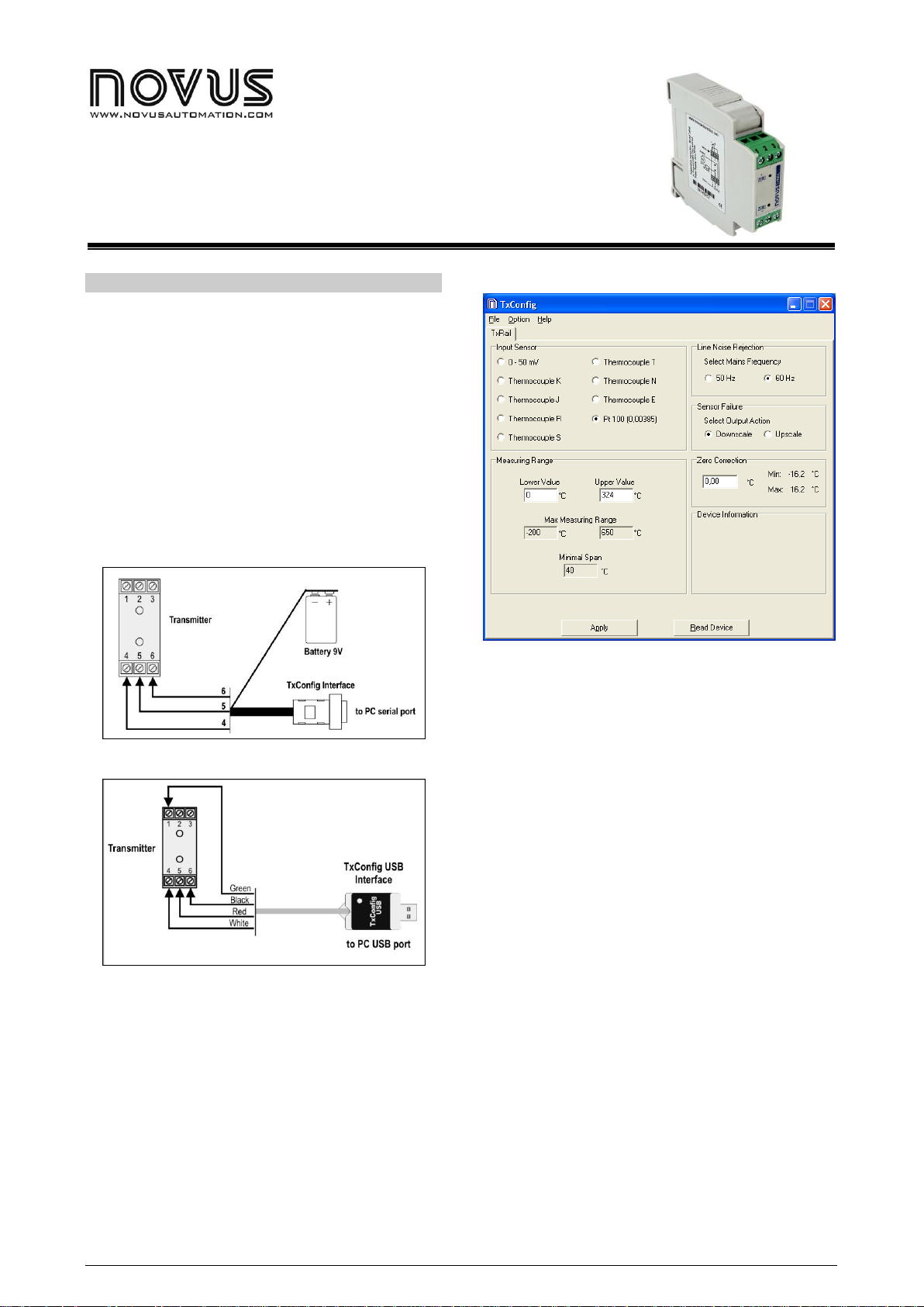
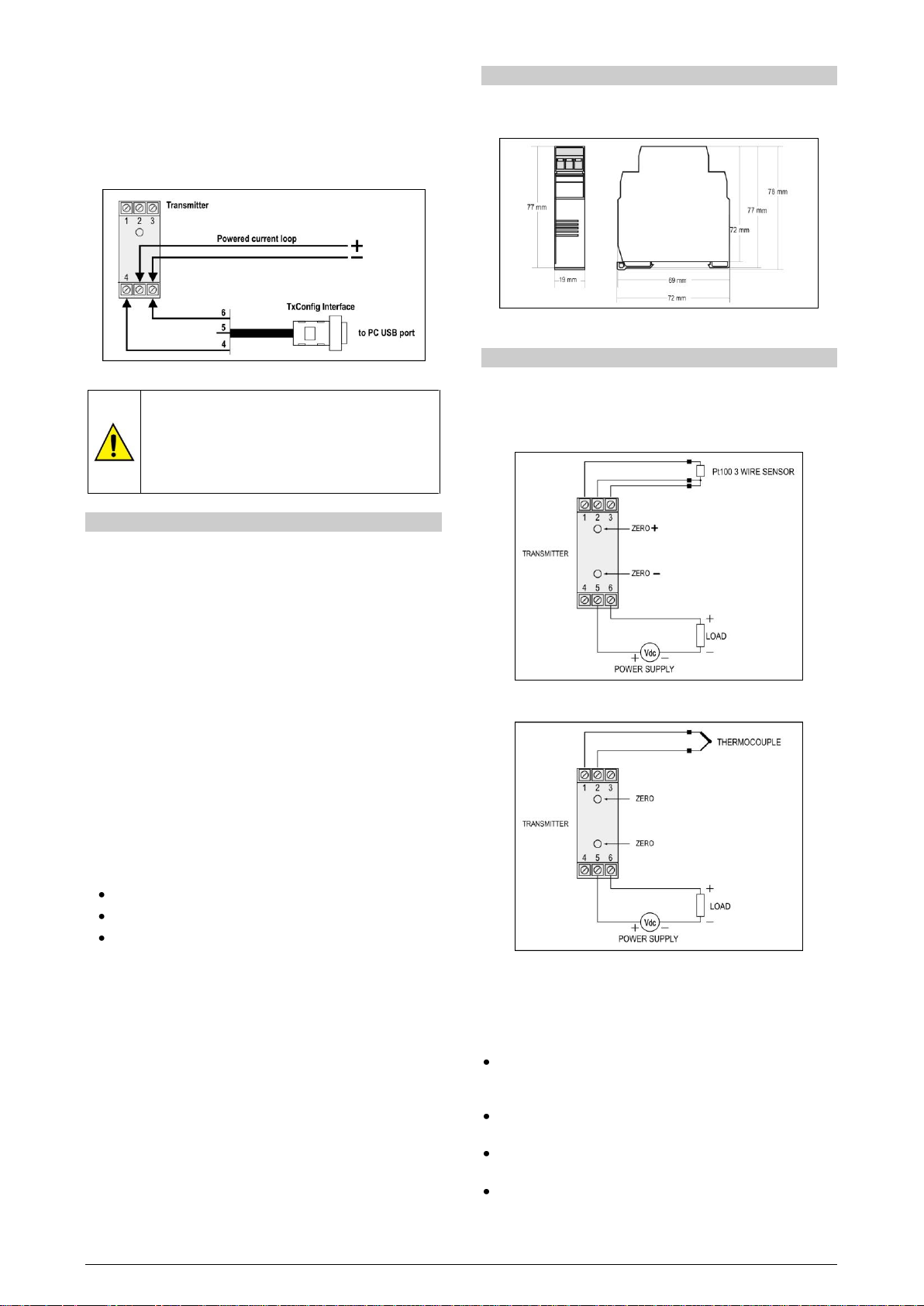
The TxConfig interface connects the transmitter to the PC, as shown
in Figures 01 and 02. There are two types of interface: TxConfig-
RS232 and TxConfig-USB.
Figure 01 – TxConfig Interface connections model RS232
Figure 02 – TxConfig Interface USB connections
Once the connection is accomplished, the software shows the
configuration options of the transmitter model attached. Access the
Help for usage instructions.
Figure 03 shows the TxConfig software main screen.
Figure 03 – TxConfig main screen
The fields in the screen mean:
1. Input Sensor: Choose the desired temperature sensor among
the available options. See Table 01.
2. Measuring Range: Defines the output scale for the input sensor.
Program here the measurement Lower Range Value and the
Upper Range Value.
When the Low Scale Limit is configured with a value higher than the
Full Scale Limit, the current output will have a decrescent behavior
(20~4 mA).
The values configured in these fields can not be beyond the
sensor measuring range. The minimum span value has to be
observed as well. See Table 01.
3. Line Noise Rejection: The transmitter incorporates a digital filter
to cancel the induced noise from the 50 or 60 Hz systems. For
better performance, select the line frequency used in your
country.
4. Sensor Failure Detection: establishes the transmitter output
behavior (upscale or down-scale) in the presence of a sensor fail.
5. Zero Correction: Allows for small sensor corrections. See item
Operating.
6. Device Information: The Device Information box contains
relevant data concerning a particular transmitter. Please pass
along this information when contacting the technical assistance
department.
7. Read Device: Brings to the screen the current transmitter
parameters configuration.
8. Apply: Sends a new configuration to the transmitter.
Note: The factory default configuration is (unless otherwise specified
or ordered):
Pt100 input, 0 to 100 °C.
60 Hz filtering and up scale (20 mA) output for sensor fail.
NOVUS AUTOMATION 1/3
TxRail 4-20 mA
The TxConfig interfaces contain dedicated circuitry
for proper communication between transmitters and
computer. Always make use of the TxConfig
interfaces for configuration purposes, otherwise the
transmitters may get damaged, voiding the
warranty.
The transmitter must be powered in order to be configured. The
TxConfig-USB interface provides the necessary power. The TxConfigRS232 interface, however, requires an auxiliary supply to guarantee a
reliable communication with the computer.
An external 9 V battery can be used for this purpose (Figure 01). An
alternative is to configure the transmitter while it is in operation; this way,
the needed energy is supplied by the current loop, as in Figure 04.
Figure 04 – TxConfig Interface connections – Loop powered
OPERATION
All input types and the 4-20 mA output current are factory calibrated
and have no need for user adjustment.
However, if desired by the user, a manual offset trim is implemented
to provide fine adjustments to the signal in the field. This is
accomplished by the front keys ZERO+ and ZERO-, located under
the frontal label in order to avoid accidental adjustments. Using a
small tool (2 mm diameter), press and hold the desired key for at
least 2 seconds to increase or decrease the output current. When the
output current is reached, the key must be released.
The offset correction can also be accomplished by the TxConfig
software. The serial adaptor can be connected to the transmitter
while it is operating in the process (Figure 04). See in Figure 03 the
Zero Correction field for this purpose.
The user must choose the sensor and configure the sensor span
which best suit the application. The sensor span must not exceed the
maximum range supported by the transmitter for a particular sensor,
neither be lower than the minimum span.
It is important to note that the transmitter accuracy is related to the
total sensor span of a sensor, regardless of the output scale (span)
configured. Example:
Pt100; maximum input span of –200 to +650 °C, 0.2 % accuracy.
Maximum error: 1.7 °C ( 0.2 % of 850 °C )
This error is the same no matter if total span is used (-200 to 650
°C) or a narrower user-defined span is used, like 0 to 100 °C.
Note: When using a Pt100 simulator, make sure the transmitter
Pt100 excitation current (0.18 mA) s compatible with the simulator
specification.
INSTALLATION
The transmitter is intended for DIN rail mounting. Its drawing is
presented in Figure 05.
Figure 05 – Transmitter dimensions
ELECTRICAL CONNECTIONS
Figures 06 and 07 below shows the transmitter connections to the
sensor and power supply. Terminals 1, 2 and 3 are used for sensor
input. For 2-wire Pt100, terminals 2 and 3 shall be connected
together.
Figure 06 – Transmitter wiring – Pt100
Figure 07 – Transmitter wiring – Thermocouple
The LOAD represents the input shunt of an instrument measuring
the 4-20 mA current loop.
NOVUS AUTOMATION 2/3
Installation Recommendations
Conductors of small electrical signals must be distant from
activation ur high-tension/current conductors, preferably passing
through grounded conduits.
A specific electrical power supply network should be provided for
instruments use only.
In controlling and monitoring applications, possible consequences
of any system failure must be considered in advance.
RC filters (47R an 100nF, serial) in inductor charges (contactors,
solenoids, etc.) are recommended.
 Loading...