

Page 1
NOVUS AUTOMATION 1/3
TxRail 4
-20 mA Transmitter
TEMPERATURE TRANSMITTER
- OPERATING MANUAL – V1.2x F
CONFIGURAÇÃO
If the default configuration or the ordered configu ration satisfies the
application, then no further configuration is necessary and the
transmitter is ready to be used. If a new setting is desired, this can be
accomplished by the TxConfig and sent to the transmi tter through
the TxConfig Interface.
The TxConfig Interface and Software compose the Transmitter
Configuration Kit, which can be purchased separately. The latest
release of this software ca n be downloaded from our web site. To
install, run the Tx_setup.exe and follow the instructions.
Serial port configuration errors may occur when other software
are sharing the same serial port. Close all serial port
applications prior to using the TxConfig software.
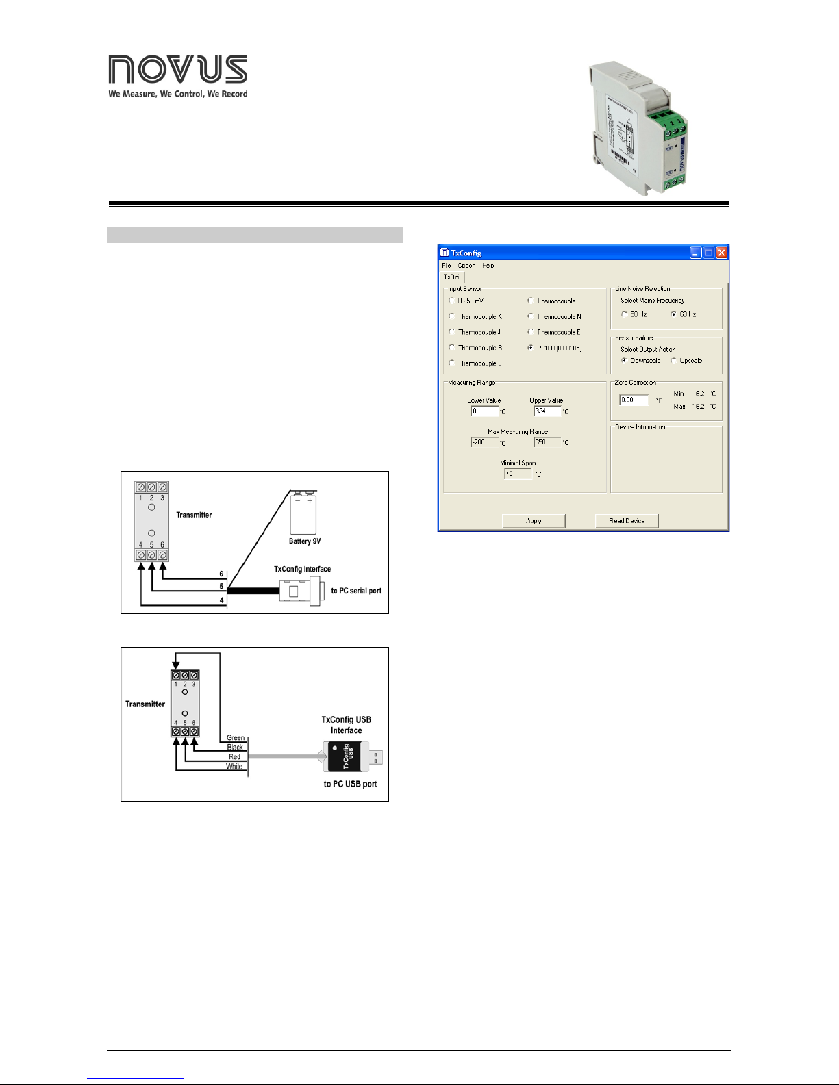
The TxConfig int erface connects the transmitter to the PC, as shown
in Fig. 1 and 2. There are two types of interface: TxConfig-RS232 and
TxConfig-USB.
Fig. 1 – TxConfig Interface connections model RS232
Fig. 2 – TxConfig Interface USB co nnections
Once the connection is accomplished, the software shows the
configuration options of the transmi tter model attached. Access the
Help for usage instructions.
Fig. 3 shows the TxConfig software main screen.
Fig. 3 – TxConfig main screen
The fields in the screen mean:
1. Input Sensor: Choose the desired temperature sensor among
the available options. See Table 1.
2. Measuring Range: Defines the outp ut scale for t he input sens or.
Program here the measurement Lower Range Value and the
Upper Range Value.
When the Low Scale Li mit is confi gured wi th a value hi gher than th e
Full Scale Limit, the current output will have a decrescent behavior
(20~4 mA).
The values configured in these fields can not be beyond the
sensor measuring range. The minimum span value has to be
observed as well. See Table 1.
3. Line Noise Rejection: The tra nsmitter inc orporates a digi tal filter
to cancel the induced noise from the 50 or 60 Hz sys tems. For
better performance, select the line frequency used in your
country.
4. Sensor Failure Detection: establishes the transmitter output
behavior (upscale or down-scale) in the presence of a sensor fail.
5. Zero Correction: Allows for small sensor corrections. See item
Operating.
6. Device Information: The Device Information box contains
relevant data concerning a particular transmitter. Please pass
along this information when c ontacting the technical assistance
department.
7. Read Device: Brings to the screen the current transmitter
parameters configuration.
8. Apply: Sends a new configuration to the transmitter.
Note: The factory default config uration i s (unless otherwi se specified
or ordered):
Pt100 input, 0 to 100 °C.
60 Hz filtering and up scale (20 mA) output for sensor fail.
Page 2
TxRail 4-20 mA
NOVUS AUTOMATION 2/3
The transmitter must be powered in order to be configured. The
TxConfig-USB interface provid es the necessa ry power. The Tx ConfigRS232 interface, however, r equires an a uxiliary s upply to gu arantee a
reliable communication with the computer.
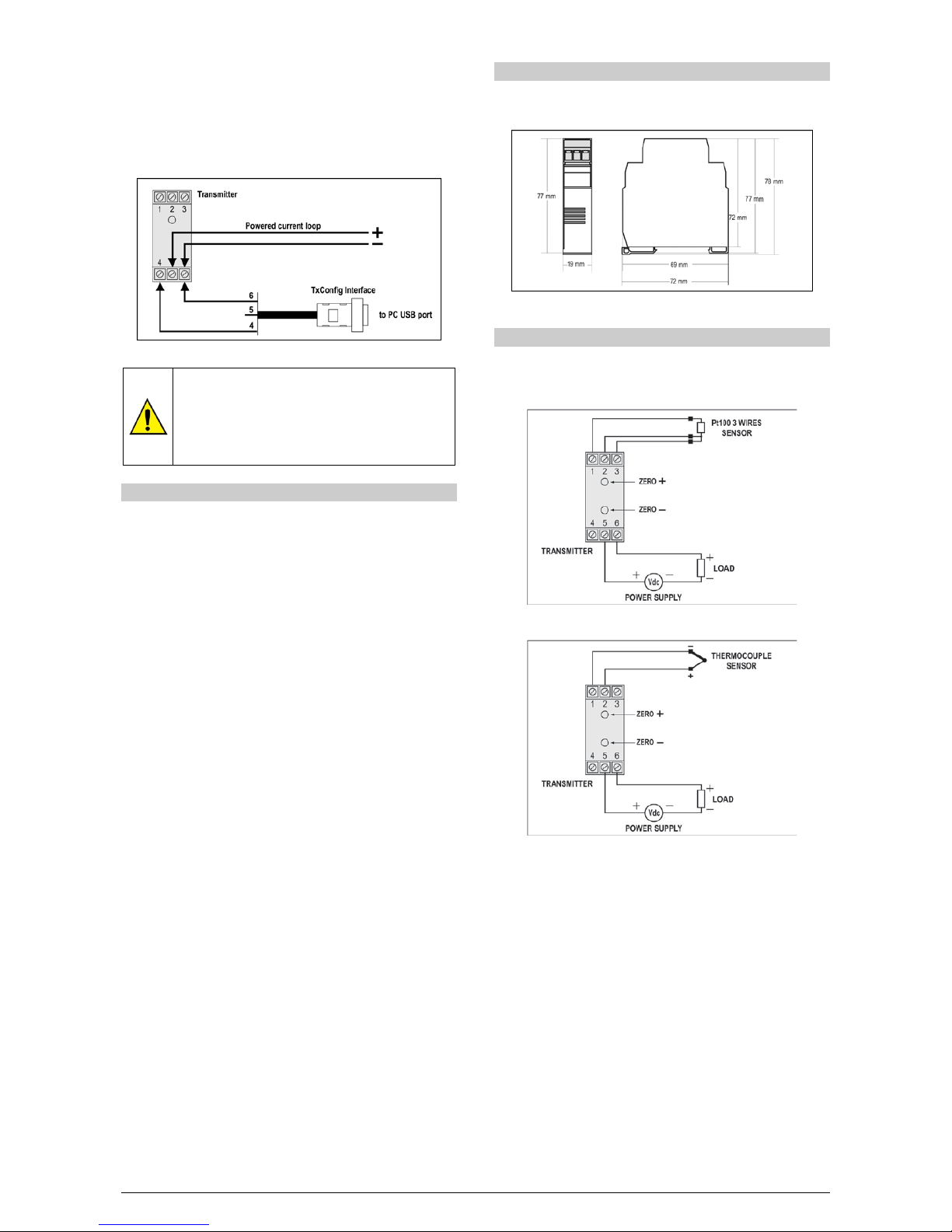
An external 9 V battery can be used for this purpose (Fig. 1). An
alternative is t o config ure the t ransmi tter whi le it is in operati on; this way,
the needed energ y is sup plie d by the curr ent loo p, as in Fig. 4.
Fig. 4 – TxConfig Interface connections – Loop powered
The TxConfig interfaces contain dedicated ci rcuitry
for proper communication between transmitters and
computer. Always make use of the TxConfig
interfaces for configuration purposes, otherwise the
transmitters may get damaged, voiding the
warranty.
OPERATION
All input types and the 4 -20 mA output c urrent are facto ry calibrated
and have no need for user adjustment.
However, if desired by th e user, a m anual offset trim is i mplemented
to provide fine adjustments to the signal in the field. This is
accomplished by the front keys ZERO+ and ZERO -, located under
the frontal label in order to avoid accidental adjustments. Using a
small tool (2 mm diameter), press and hold the desired key for at
least 2 seconds to increase or decrease the output cur rent. Whe n the
output current is reached, the key must be released.
The offset correction can also be accomplished by the TxConfig
software. The serial adaptor can be connected to the transmitter
while it is operating in the process ( Fig. 4). See in Fig. 3 the Zero
Correction field for this purpose.
The user must choose the sensor and configure the sensor span
which best suit the application. The s ens or span m ust not exc eed t he
maximum range supported by the t ransmitter fo r a particular sens or,
neither be lower than the minimum span.
It is important to note that the t ransmitter accuracy is related to the
total sensor span of a senso r, regardless of the output s cale (span)
configured. Example:
• Pt100; maximum input span of –200 to +650 °C, 0.2 % accuracy.
• Maximum error: 1.7 °C ( 0.2 % of 850 °C )
• This erro r is the same no matter i f to ta l s pan is used ( -200 to 650
°C) or a narr ow er u ser-defined span is used, like 0 to 100 °C.
Note: When using a Pt100 simulator, make sure the transmitter
Pt100 excitation current (0.18 mA) s compatible with the simulator
specification.
INSTALLATION
The transmitter is intended for DIN rail mounting. Its drawing is
presented in Fig. 5.
Figure 05 – Transmitter dimensions
ELECTRICAL CONNECTIONS
Fig. 6 and 7 below shows the transmi tter connections to the sensor
and power supply. Terminals 1 , 2 and 3 are used for sensor i nput.
For 2-wire Pt100, terminals 2 and 3 shall be connected together.
Fig. 6 – Transmitter wiring – Pt100
Fig. 7 – Transmitter wiring – Thermocouple
The LOAD represents the input shunt of an instrument measuring
the 4-20 mA current loop.
Installation Recommendations
• Conductors of small electrical signals must be distant from
activation ur high-tension/current conductors, preferabl y passing
through grounded conduits.
• A specific el ectrical power supply network s hould be provided for
instruments use only.
• In controlli ng and m oni toring appl ic ati ons, pos si bl e cons eque nces
of any system failure must be considered in advance.
• RC filters (47 R an 100nF, serial ) in inductor c harges (contactors,
solenoids, etc.) are recommended.
Page 3

TxRail 4-20 mA
NOVUS AUTOMATION 3/3
SPECIFICATIONS
Sensor input: User defined. The supported sensors are listed in
Table 01, along with their maximum ranges.
Thermocouples: Types J, K, R, S, T, N and E, to IEC 60584
(ITS-90).
Impedance >> 1 M
Ω
Pt100: Excitation: 0.18 mA, 2 or 3-wire connection
(for 2-wire sensors, tie terminals 2 and 3
together).
α = 0.00385, according to IEC 60751 (ITS-90).
Voltage: 0 to 50 mVdc. Impedance >> 1 MΩ
SENSOR TYPE RANGE
MINIMUM
MEASUREMENT SPAN
Thermocouple K 0 to 1370 °C 100 °C
Thermocouple J 0 to 760 °C 100 °C
Thermocoupler R
0 to 1760 °C
400 °C
Thermocouple S
0 to 1760 °C
400 °C
Thermocouple T
0 to 400 °C
100 °C
Thermocouple N 0 to 1300 °C 100 °C
Thermocouple E 0 to 720 °C 100 °C
Pt100 -200 to 650 °C 40 °C
Voltage
0 to 50 mV
5 mV
Table 1 – Transmitter input sensors
Output: 2-wire 4-20 mA, linear with respect to the measured
temperature.
Total accuracy: better than 0.3 % of the maximum range for
thermocouples and 0.2 % for Pt100 and voltage;
Resolution: 0.004 mA (12 bits)
Resposta time: < 100 ms
Power supply: 18 to 35 Vdc, across the transmitter;
Maximum load (RL): RL (Ohms max.) = (Vcc – 12) / 0.02 [Ω]
Where: Vcc = Power supply voltage
Operating temperature: -40 to 85 °C
Humidity: 0 a 90 % RH
Electromagnetic compatibility: EN 50081-2, EN 50082-2
No isolation between the sensor and the 4-20 mA loop.
Internal protection against polarity inversion.
Cold junction compensation for thermocouples.
Housing: ABS plastic. Dimensions: Refer to Fig. 05.
SAFETY INFORMATION
Any control system des i gn s hould take into account th at a ny pa rt of the
system has the potential to fail. This product is not a protection or
safety device and i ts al a rms ar e no t i n tend ed t o protect against product
failures. Independent safety devices should be always provided if
personnel or property are at risk.
Product performance and specifications may be affected by its
environment and instal lation. It’s use r’s responsibili ty to assure prope r
grounding, shielding, cable routing and electrical noise filtering, in
accordance with local regulations, EMC standards and good installation
practices.
SUPPORT AND MAINTENANCE
This product contains no serviceable parts inside. Contact our local
distributor in cas e you need authorized servi ce. For troubleshooting,
visit our FAQ at www.novusautomation.com
.
LIMITED WARRANTY AND LIMITATION OF
LIABILITY
NOVUS warrants to t he o rigi n al p urc h as er th at t hi s p rod uc t is f re e f ro m
defects in material and workmanship und er normal use and service
within one (1) year from the da te of shipment from facto ry or from its
official sales channel to the original purchaser.
NOVUS liability under this warranty shall not in any case exceed the
cost of correctin g defects in the produc t or of supplying replacem ent
product as herein provided and upon the expiration of the warranty
period all such liability shall terminate.
For complete information on warranty and liability limitations, check
appropriate section in our web site: www.novusautomation.com
.
 Loading...