

NOVUS TxMiniBlock User Manual
The TxConfig interface has a complex electronic circuit.
ace or cable connection to
; the product will be damaged and this damage is not
TxMiniBlock
TEMPERATURE TRANSMITTER – OPERATING MANUAL V1.0x B
1 INTRODUCTION
TxMiniBlock is a 4-20 mA 2-WIRE Pt100 temperature transmitter to be
assembled in heads. The desired temperature measurement range as well
as other transmitter features can be easily configured through the TxConfig
software and the TxConfig-USB interface.
The output current has a linear behavior relative to the temperature
measured by t he sensor.
2 SPECIFICATIONS
Sensor input: Pt100.
Maximum Range: -200 to 650 º C
Minimum Span: 40 ºC
3-wires, Excitation of 0.20 mA, α= 0.00385, according
NBR 13773.
To use 2-wires Pt100, connect together terminals 2 and
3.
Total accuracy (Tam b 25 ºC) : Maximum error 0.2 % of the maximum range
for Pt100;
Response time: < 100 ms
Output: Current of 4-20 mA or 20-4 mA, 2-wires; linear relative to the
temperature measured by the sensor.
Output resolution: 0.004 mA (12 bit)
Power supply: 12 to 35 Vdc across the transmitter
Maximum load (RL): RL (max.) = (Vdc – 12) / 0.02 [Ω]
Where: Vdc= Power supply v oltage (12 to 35 Vdc)
Operating temperature: -40 to 50 °C
Humidity: 0 to 90 % RH
Calibration thermal drift: ± 40 ppm / °C full range
Electromagnetic compatibility: EN 50081-2, EN 50082-2
No electrical isolation between the s ensor and the 4-20 mA loop.
Internal protection against supply v oltage polarity inversion.
Housing in ABS, 34 mm diameter an d ma xim u m heig ht of 18 mm.
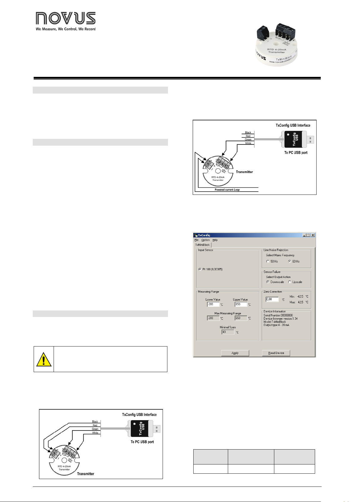
During setup, the transmitter must be powered electrically. The TxConfig
interface itself supplies the power, but this depends on the comput er used.
Another way is to run the setup with the transmitter connected to this
process, using the energy from the same source that feeds this process
(loop). See Figure 02.
Figure 02 – TxConfig Interface connections – Loop powered
After the connections are made, the user must run the TxConfig software
and, if necessary, use the Help topic to configur e the transmitt er.
Figure 03 shows the main screen of the TxConfig software.
3 CONFIGURATION
If the Pt100 sensor is already configured, no intervention is necessary;
installation can be immediately performed. When a configuration change is
required, it can be made with the TxConfig software; it is then sent to the
transmitter using the TxConfig Interface.
Do not use any other interf
USB
covered under warr ant y.
TxConfig interface and software are comprised in the Transmitter Setup Kit
that can be purchased from the manufacturer or from authorized dealers. The
software can be upgraded for free at the manufacturer’s website. To install, run
Tx_setup.exe and follow the instr uct i ons.
The interface connects the transmitter to the computer, as show in Figure 01.
NOVUS AUTOMATION 1/2
Figure 01 – TxConfig USB Interface connections
Figure 03 – Main screen of the TxConfig software
The fields in this screen have the follow ing purposes:
1. Input Sensor: Pt100 (0.00385).
2. Measurement Range: Defines the transmitter measurement range.
Lower range limit corresponds to the desired temperature for a current of
4 mA.
Upper range limit corresponds to the desired temperature for a current of
20 mA.
When the Lower Limit is set with a value higher than the Upper Limit value, the
output current operates between 20 and 4 mA.
The chosen values cannot exceed the Sensor Range shown in this field
and cannot establish a band with width (span) lower than the Minimum
Range value indicated below in this field. See table below.
Type of Sensor
Pt100 -200 a 650 °C 40 °C
Maximum
Measurement Range
Table 01 – Transmitter input sensor
Minimum
Measurement Range
TxMiniBlock Transmitter
3. Filtration Optimization: Filters the measurements made by the
transmitter eliminating interferences from the electrical system that feeds
the process.
4. Sensor Failure: Establishes the behavior of the output when problems are
presented by the sensor. When Minimum is selected, the output current shifts
to < 4 mA (down-scale), typically used in refrigeration. When Maximum is
selected, if shifts t o > 20 mA (up-scale), typically us ed for heating.
5. Zero Correction: Corrects minor errors presented by the transmitter, for
example, wh en the sensor is changed. See item Operation in this manual.
6. Transmitter Information: In this field, there are data that identify the
transmitter. This information must be informed in any consultation with the
manufacturer.
7. Read Configuration: When pressed, this allows one to read the
configuration on the transm itter connected.
8. Send Configuration: When pressed, this allows one to send the
configuration to the transmitter connected.
Note: If, on the purchase order, the user does not define a specific
configuration, the following configur ation will be s et:
• Pt100 sensor, range 0 to 100 °C, 0 °C zero correction.
• Filter to 60 Hz and maximum output for sensor failures.
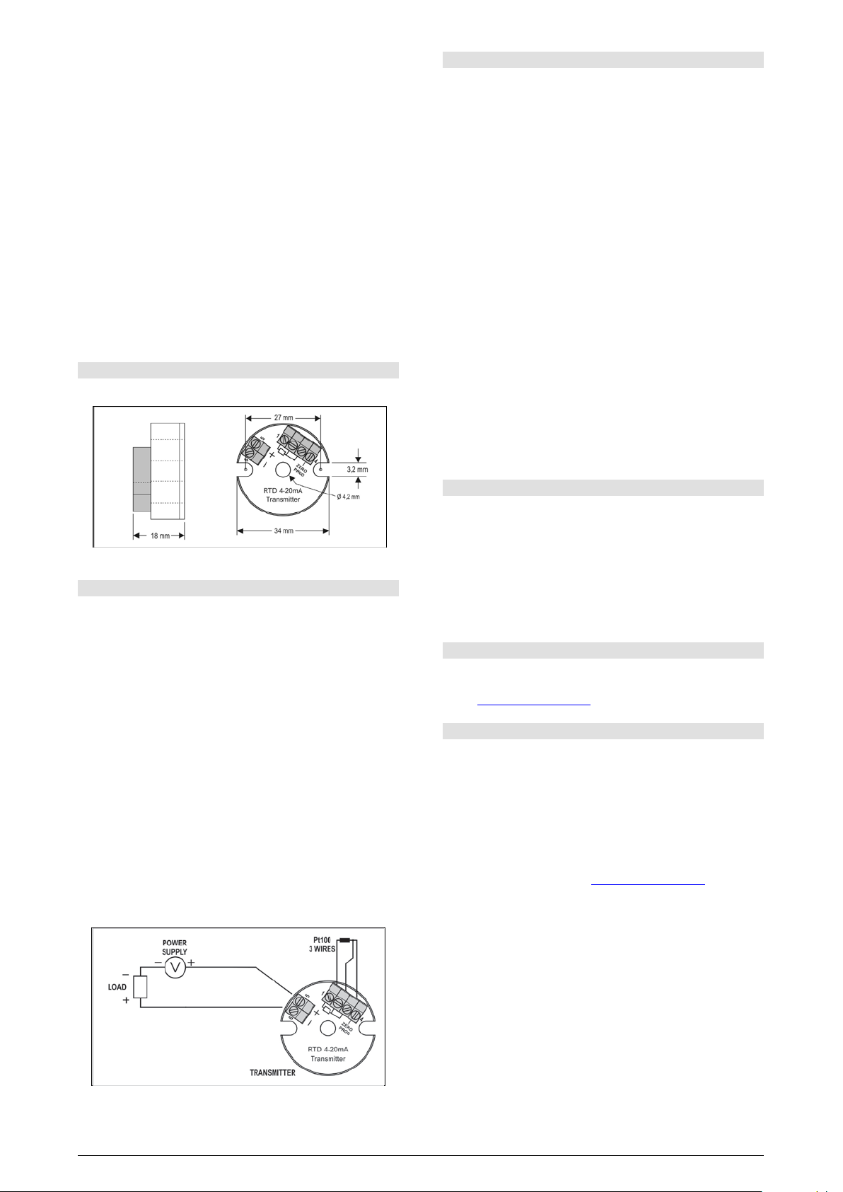
4 MECHANICAL INSTALLATION
The TxMiniBlock transmitter is suitable to be installed on heads.
6 OPERATION
The sensor input is factory calibrated. Recalibration in the field is not
recommended, but it can be accomplished through the TxConfig software.
Contact the factory for the calibration procedure.
When necessary, fine adjustments to the transmitter output current can be
accomplished directly at the transmitter. To do so, short circuit transmitter
terminals 1 and 4. After 2 seconds, the output current starts to increase
gradually until it reaches 0.8 mA above the initial value. After reaching that
value, it drops to 0.8 mA below the initial value, increasing gradually again.
The user must monitor the output current and open the circuit when the
current reaches the desir ed value.
The offset correction can also be accomplished through the TxConfig
software. The TxConfig interface can be connected to the transmitter while it
is operating in the process. See in Figure 03 the Zero Correction field in the
main screen of the TxConfig software.
The user must choose the sensor span most suitable to the application. The
maximum and minimum sensor spans are limited in the TxMiniBlock and in
the TxConfig software. The user can configure any value within those two
limits.
It is important to note that the accuracy of the transmitter is always based on
the maximum ra nge of the Pt100 sensor, regardless of the configured span. .
Example:
• Pt100 maximum span = 850 °C; 0.2% accuracy.
• Maximum err or = 1.7 °C (0.2 % de 850 °C)
The error is the same no matter if total span is used (-200 to 650 °C) or a
narrower user-defined sp an is used, lik e 0 to 100 °C.
Note: When using a Pt100 simulator, make sure the TxMiniBlock’s Pt100
excitation current (0.20 mA) is compatible with the simulator specification.
Figure 04 – Transmitter dimensions
5 ELECTRICAL INSTALLATION
Polyamide h ousing for the t erminals.
Section of the wire: 0.14 a 1.0 mm².
Recommended Torque: 0.8 Nm.
RECOMMENDATI ONS FOR INSTALLATION
• Input signal conductors should run away from power and contactor
wires, if possible, i n grounded conduits.
• The instruments must be powered by a suitable network for
instrumentation.
• System failure should always be taken into account when designing a
system to avoid irreversible damage to equipment or people. Installing
RC filters (47 Ω and 100 nF, in series) is strongly recommended at
contactor coi ls or any other inductors.
ELECTRICAL CONNECTIONS
Figure 05 below shows the transmitter wiring. Terminals 1, 2 and 3 are used
for sensor input. For 2-wire Pt100, terminals 2 and 3 shall be connected
together. The LOAD represents the input shunt of an instrument measuring
the 4-20 mA current loop.
The figure below shows the electrical connections required. Terminals 1, 2
and 3 are used for the Pt100 input. For 2-wire Pt100, terminals 2 and 3 must
be interconnected.
7 SAFETY INFORMATION
Any control system design should take into account that any part of the
system has the potential to fail. This product is not a protection or safety
device and its alarms are not intended to protect against product failures.
Independent safety devices should be always provided if personnel or
property are at risk.
Product performance and specifications may be affected by its environment
and installation. It’s user’s responsibility to assure proper grounding,
shielding, cable routing and electrical noise filtering, in accordance with local
regulations , EMC standards and good installation practices.
8 SUPPORT AND MAINTENANCE
This product contains no serviceable parts inside. Contact our local
distributor in case you need authorized service. For troubleshooting, visit our
FAQ at www.novusautomation.com
.
9 LIMITED WARRANTY AND LIMITATION OF LIABILITY
NOVUS warrants to the original purchaser that this product is free from
defects in material and workmanship under normal use and service within
one (1) year from the date of shipment from factory or from its official sales
channel to the original purchaser.
NOVUS liability under this warranty shall not in any case exceed the cost of
correcting defects in the product or of supplying replacement product as
herein provided and upon the expiration of the warranty period all such
liability shall terminate.
For complete information on warranty and liability limitations, check
appropriate section in our web site: www.novusautomation.com
.
Figure 05 – Transmitter electrical connections – Pt100
The LOAD represents the input shunt of an instrument measuring the 4-20
mA current loop (indicator, controller, recorder, etc).
NOVUS AUTOMATION 2/2
 Loading...