

Page 1

USER`S MANUAL VER. 1.0
CCTV COLOR MONITORS
NVM-015CH
NVM-017CH
NVM-019CH
NVM-021CS
NOVUS SECURITY Sp. z o.o.
359 Pulawska Str., 02-801 Warsaw, Poland
tel: +4822-546-0-500; fax: +4822-546-0-519
[email protected]; www.novuscctv.com
© Copyright 2003, NOVUS SECURITY Sp. z o.o.
Page 2

CCTV – color monitors user’s manual, v.1.0
© Copyright 2003, Novus Security Sp. z o.o. All rights reserved.
2
Table of Contents
Table of Contents
1. FCC Information 3
2. Safety Precautions 4
3. General Features 6
4. NVM-015CH Front and Rear Views 7
5. NVM-017CH Front and Rear Views 8
6. NVM-019CH Front and Rear Views 9
7. NVM-021CS Front and Rear Views 10
8. Operating Instructions 11
9. Specifications 12
Page 3

CCTV – color monitors user’s manual, v.1.0
© Copyright 2003, Novus Security Sp. z o.o. All rights reserved.
3
FCC INFORMATION
1. FCC Information
This equipment has been tested and found to comply with the limits for a class B
digital device, pursuant to Part 15 of the FCC Rules. These limits are designed to provide
reasonable protection against harmful interference in a residential installation. This
equipment generates, uses and can radiate radio frequency energy and, if not installed and
used in accordance with the instructions, may cause harmful interference to radio
communications.
However, there is no guarantee that interference will not occur in a particular
installation. If this equipment does cause harmful interference to radio or television
reception, which can be determined by turning the equipment off and on, the user is
encouraged to try to correct the interference by one or more of the following measures:
• Reorient or relocate the receiving antenna;
• Increase the separation between the equipment and receiver;
• Connect the equipment into an outlet on a circuit different from that to which the receiver is
connected;
• Consult the dealer or an experienced radio/TV technician for help;
Shielded interface cables and A.C. power cord, if any, must be used in order to comply with
emission limits.
Changes or modifications not expressly approved by the party responsible for
compliance could void the user’s authority to operate the equipment.
Page 4

CCTV – color monitors user’s manual, v.1.0
© Copyright 2003, Novus Security Sp. z o.o. All rights reserved.
4
SAFETY PRECAUTIONS
2. Safety Precaution
1. Operate this unit only from the type of power source indicated on the label.
2. Do not block or cover ventilation openings on the back or bottom of the monitor cabinet.
3. Do not place this monitor near a radiator or heating vent.
4. Do not push objects of any kind through cabinet openings. This may result in fire or electrical
shock.
5. Before adding attachments always ask a service technician to perform routine safety tests to
determine that equipment is in safe operating condition. Ground potential tests should be part of
the routine safety check made by the service technician.
6. Do not place monitor on an unstable cart, stand, or shelf where it may fall and injure personnel or
damage equipment.
7. Route power cords so that they cannot be walked upon or tripped over. Do not allow anything to
rest on the power cord.
8. Do not install monitor in wet areas, or where it may be exposed to rain or water. Do not spill liquid
of any kind on the unit.
9. Unplug the power cord from the unit before cleaning the display. Use only a damp cloth. Do not
use alcohol, spirits, or ammonia to clean the display.
DO NOT ATTEMPT TO CLEAN THE INTERIOR OF THIS UNIT - - THIS ACTION
MUST BE PERFORMED BY THE SERVICE TECHNICIAN AS REQUIRED DURING
NORMAL MAINTENANCE.
10. Refer all servicing to qualified service personnel. REMOVAL OF BACK COVER BY
UNAUTHORIZED PERSONNEL MAY EXPOSE THE USER TO DANGEROUS VOLTAGES
OR OTHER HAZARDS.
11. Unplug the unit immediately and notify the service technician.
A. If liquid has been spilled into the display or the display has been exposed to rain or water.
B. If the unit has been dropped or the cabined damaged.
C. If fuses continue to blow.
D. If the power cord is damaged or frayed.
E. If a distinct change from normal operation is apparent.
Page 5

CCTV – color monitors user’s manual, v.1.0
© Copyright 2003, Novus Security Sp. z o.o. All rights reserved.
5
SAFETY PRECAUTIONS
When replacement parts are required, be sure that the service technician uses components
specified by the manufacturer which have the same characteristics as the original parts.
UNAUTHORIZED SUBSTITUTIONS MAY RESULT IN FIRE, ELECTRICAL
SHOCK OR OTHER HAZARDS.
Upon completion of any service or repairs, ask the technician to perform
safety checks to determine that the equipment is in safe operating condition.
WARNING
SERIOUS SHOCK HAZARDS EXIST WITHIN THE COVERS OF THIS MONITOR.
DO NOT OPEN THE COVERS UNDER ANY CIRCUMSTANCES,
THERE ARE NO USER SERVICEABLE COMPONENTS INSIDE
Page 6
CCTV – color monitors user’s manual, v.1.0
© Copyright 2003, Novus Security Sp. z o.o. All rights reserved.
6
GENERAL FEATURES
3. General Features
1. Compatible With : NTSC / PAL System
2. Scanning System :
NTSC, 15750 Hz / 60 Hz / 525 Lines
PAL 15625 / 50 Hz / 625 Lines,
3. Video Input Signal : CVBS1 / CVBS2 / S-Y/C
4. Audio Input Signal : AU1 / AU2
5. Input Power : 100~240V AC or 23V DC +/- 1V(Option)
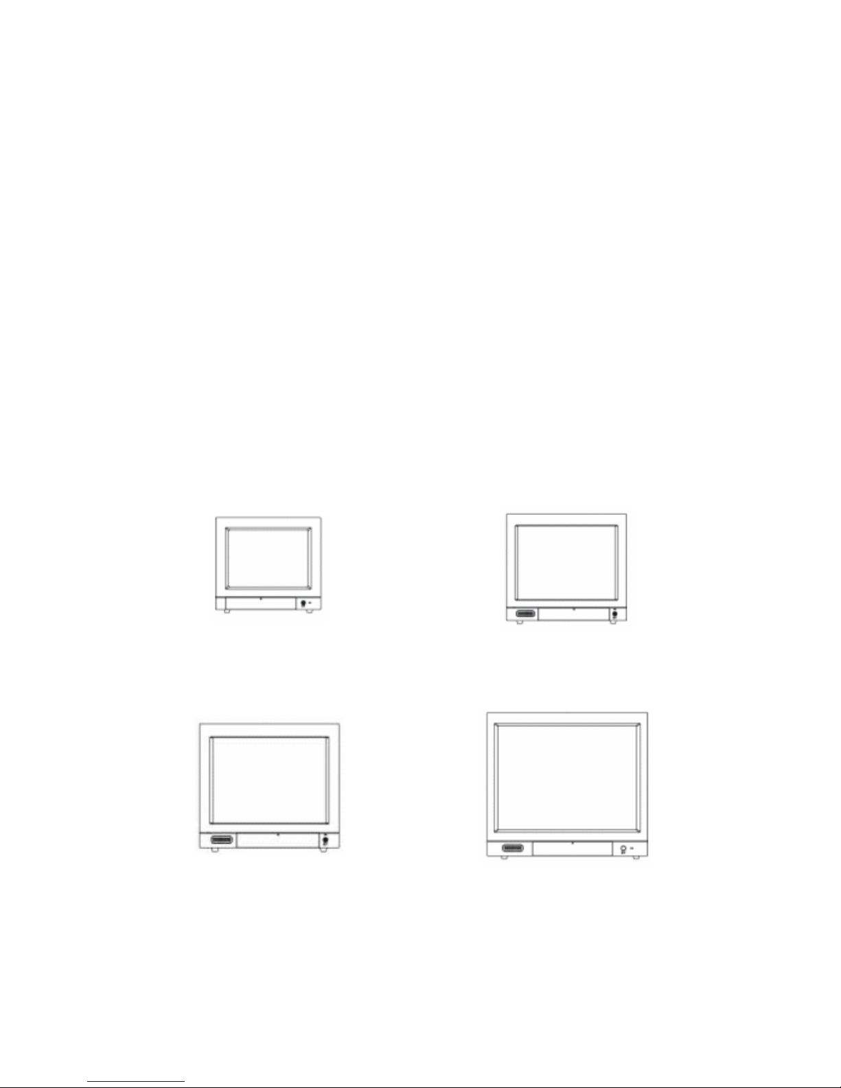
STANDARD SYSTEM COMPONENTS AND ATTACHMENTS
NVM-015CH
NVM-017CH
NVM-019CH
NVM-021CS
Page 7
CCTV – color monitors user’s manual, v.1.0
© Copyright 2003, Novus Security Sp. z o.o. All rights reserved.
7
NVM-015CH Front and Rear Views
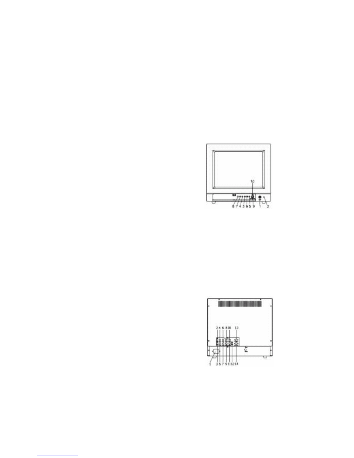
4. NVM-015CH Front and Rear Views
Front View
1. Power On/Off Switch
2. Power-On Indicator
3. Contrast Adjustment
4. Brightness Adjustment
5. Tint Adjustment
6. Color Adjustment
7. Sharpness Adjustment
8. Volume Adjustment
9. CVBS1 / CVBS2 / S-Y/C Switch
10. Audio1 / Audio2 Select Switch
NVM-015CH
Rear View
1. Power Inlet
2. Video 1 Load Impedance Switch
3. Video 2 Load Impedance Switch
4. Video 1 Input : BNC Connector
5. Video 1 Output : BNC Connector
6. Video 2 Input : BNC Connector
7. Video 2 Output : BNC Connector
8. Audio 1 Input : RCA Jack
9. Audio 1 Output : RCA Jack
10. Audio 2 Input : RCA Jack
11. Audio 2 Input : RCA Jack
12. S-Y/C Load Impedance Switch
13. S-Y/C Input Connector
14. S-Y/C Output Connector
NVM-015CH
Page 8
CCTV – color monitors user’s manual, v.1.0
© Copyright 2003, Novus Security Sp. z o.o. All rights reserved.
8
NVM-017CH Front and Rear Views
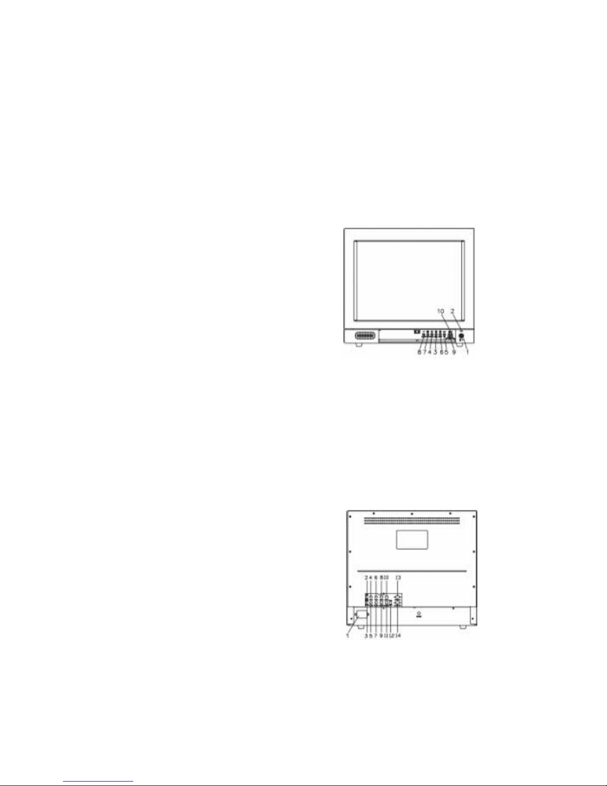
5. NVM-017CH Front and Rear Views
Front View
1. Power On/Off Switch
2. Power-On Indicator
3. Contrast Adjustment
4. Brightness Adjustment
5. Tint Adjustment
6. Color Adjustment
7. Sharpness Adjustment
8. Volume Adjustment
9. CVBS1 / CVBS2 / S-Y/C Switch
10. Audio1 / Audio2 Select Switch
NVM-017CH
Rear View
1. Power Inlet
2. Video 1 Load Impedance Switch
3. Video 2 Load Impedance Switch
4. Video 1 Input : BNC Connector
5. Video 1 Output : BNC Connector
6. Video 2 Input : BNC Connector
7. Video 2 Output : BNC Connector
8. Audio 1 Input : RCA Jack
9. Audio 1 Output : RCA Jack
10. Audio 2 Input : RCA Jack
11. Audio 2 Input : RCA Jack
12. S-Y/C Load Impedance Switch
13. S-Y/C Input Connector
14. S-Y/C Output Connector
NVM-017CH
Page 9
CCTV – color monitors user’s manual, v.1.0
© Copyright 2003, Novus Security Sp. z o.o. All rights reserved.
9
NVM-019CH Front and Rear Views
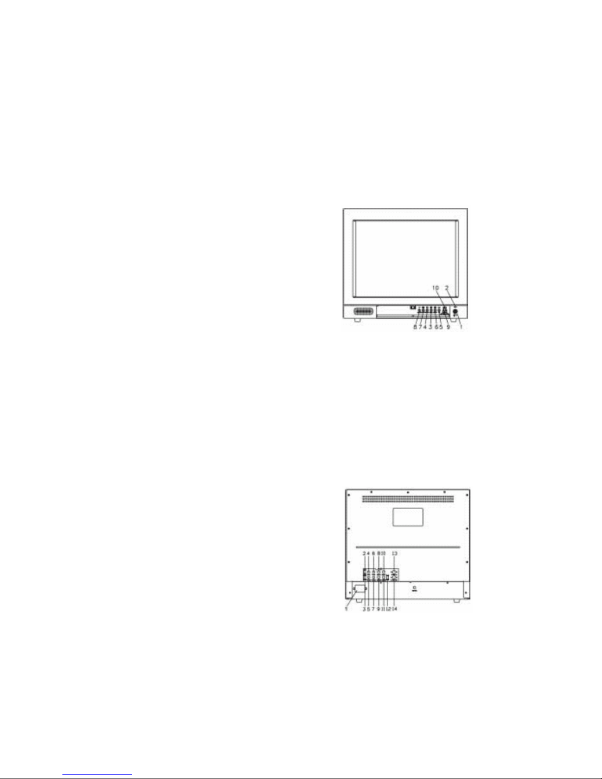
6. NVM-019CH Front and Rear Views
Front View
1. Power On/Off Switch
2. Power-On Indicator
3. Contrast Adjustment
4. Brightness Adjustment
5. Tint Adjustment
6. Color Adjustment
7. Sharpness Adjustment
8. Volume Adjustment
9. CVBS1 / CVBS2 / S-Y/C Switch
10. Audio1 / Audio2 Select Switch
NVM-019CH
11. Underscan Select Switch
12. 16:9 Select Switch
Rear View
1. Power Inlet
2. Video 1 Load Impedance Switch
3. Video 2 Load Impedance Switch
4. Video 1 Input : BNC Connector
5. Video 1 Output : BNC Connector
6. Video 2 Input : BNC Connector
7. Video 2 Output : BNC Connector
8. Audio 1 Input : RCA Jack
9. Audio 1 Output : RCA Jack
10. Audio 2 Input : RCA Jack
11. Audio 2 Input : RCA Jack
12. S-Y/C Load Impedance Switch
13. S-Y/C Input Connector
14. S-Y/C Output Connector
NVM-019CH
Page 10
CCTV – color monitors user’s manual, v.1.0
© Copyright 2003, Novus Security Sp. z o.o. All rights reserved.
10
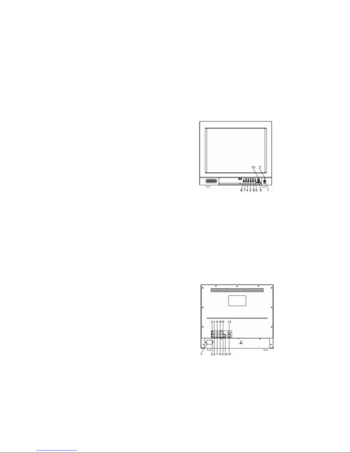
NVM-021CS Front and Rear Views
7. NVM-021CS Front and Rear Views
Front View
1. Power On/Off Switch
2. Power-On Indicator
3. Contrast Adjustment
4. Brightness Adjustment
5. Tint Adjustment
6. Color Adjustment
7. Sharpness Adjustment
8. Volume Adjustment
9. CVBS1 / CVBS2 / S-Y/C Switch
10. Audio1 / Audio2 Select Switch
NVM-021CS
11. Underscan Select Switch
12. 16:9 Select Switch
Rear View
1. Power Inlet
2. Video 1 Load Impedance Switch
3. Video 2 Load Impedance Switch
4. Video 1 Input : BNC Connector
5. Video 1 Output : BNC Connector
6. Video 2 Input : BNC Connector
7. Video 2 Output : BNC Connector
8. Audio 1 Input : RCA Jack
9. Audio 1 Output : RCA Jack
10. Audio 2 Input : RCA Jack
11. Audio 2 Input : RCA Jack
12. S-Y/C Load Impedance Switch
13. S-Y/C Input Connector
14. S-Y/C Output Connector
NVM-021CS
Page 11

CCTV – color monitors user’s manual, v.1.0
© Copyright 2003, Novus Security Sp. z o.o. All rights reserved.
11
Operating Instructions
8. Operating Instructions
1. Place the monitor on a flat and firm surface (see Safety Precautions on page 4).
2. This monitor can be operated between 100VAC to 240VAC.
3. Plug the power cord into AC outlet on the wall.
4. Plug the power cord into AC outlet on the wall.
5. Link the audio/video terminal from your devices into the audio/video in RCA/BNC connectors of
the monitor.
6. Turn your device system power switch ON. then turn the monitor power switch on. The power
indicator will be ON at this moment.
7. Allow about 30 seconds for the display tube to warm up, then the image should appear on the screen.
8. The monitor will detect the frequency of the input signal automatically, and the image may be
adjusted through the function VR on front control panel.
9. Adjust the user controls to optimize picture quality.
WARNING
1. ”DC IN” can connect to external DC power supply at voltage range 22-24 volts. Monitor can
function properly with this ”DC IN”.
2. ”DC OUT” can provide DC 23 volts at maximum current 250 mA to a device such as a camera, and
monitor can still function properly.
Page 12
CCTV – color monitors user’s manual, v.1.0
© Copyright 2003, Novus Security Sp. z o.o. All rights reserved.
12
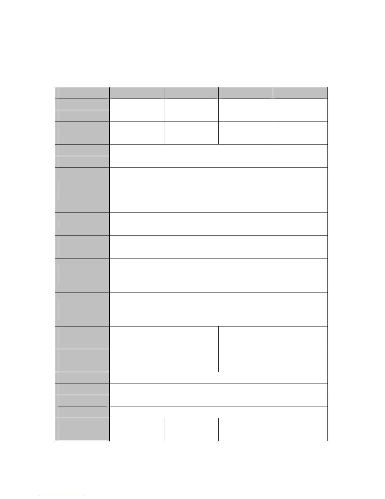
Specifications
9. Specifications
Model NVM-015CH NVM-017CH NVM-019CH NVM-021CS
CRT Size 15” 17” 19” 21”
CRT Dot Pitch 0.28 mm 0.28 mm 0.27 mm 0.76 mm
Power
Consumption
68 W 72 W 78 W 70 W
Operation System NTSC / PAL (Auto Scan)
Power Supply AC 100 ~ 240 V, 60/50 Hz
Input / Output
Video
2 Inputs (BNC) 75Ohm or Hi-Z
2 Loop Through Outputs (BNC)
1 Y/C (Mini-DIN 4 Pin) 75Ohm or Hi-Z
1 Loop Through Output
Audio
2 Inputs (RCA) Hi-Z
2 Loop Through Outputs
Built-in S-VHS
(Y/C)
Yes
Horizontal
Resolution
700 lines, Y/C more than 800 lines
450 lines, Y/C
more than 500
lines
Front Panel
Control
Power switch, Video select switch, Audio select switch, Contrast, Brightness,
Color , Sharpness,
Tint and Volume
Underscan Select
Switch
No Yes
16:9 Select
Switch
No Yes
Linearity Horizontal: 10%; Vertical: 10%
Temperature 0°C ~ 50°C
Humidity 10 ~ 85%
Case Metal
Dimension
W x H x D [mm]
356x333x381 405x370.5x406 442x405x446 480x462x439.3
Page 13

All rights reserved © NOVUS SECURITY
NOVUS SECURITY Sp. z o.o.
 Loading...