

Page 1
NOVUS AUTOMATION 1/3
LOOP
CURRENT INDICATOR – INSTRUCTION MANUAL – V1.0x C
INTRODUCTION
LoopView is a 4-20 mA current loop indicator with 2 wires, low
consumption, with excellent accuracy and that allows the device to
indicate several variables such as pressure, flow, pH, temperature,
acceleration, among others.
It is possible to perform the configuration, to display the indications,
adjustment functions, filters and calibration, in a fast and practical
way, directly on the indicator.
FEATURES
SIGNAL INPUT
The type of input to be used by the indicator is described in the table
below:
TYPE RANGE OF MEASUREMENT
4-20 mA
Linear Analog Signal
Programmable indication of
-1999 to 9999
FUNCTION AD-L and AD-H (
AD-L; AD-H
)
From the knowledge of the process condition x indication (PV)
relationship of two process points, the total indication range must be
defined.
The PV values for the two known process points are entered in the
ad-L
and
ad-H
parameters which are displayed in the configuration
cycle. Note that for each entered input value, confirmation is required
by pressing the key.
By using these functions, the parameters of the indication limits are
automatically set by the indicator.
FUNCTION LINE (
LINE
)
It allows the application of small corrections in the measurements
(approximately 1 % of the measurement range), picking up a
midpoint in the calibration interval. Example: the 4-20 mA range is
defined, with a programmable interval between 0-1000, the value
measured in 12 mA (midpoint of the calibration interval), must be
500, but when a LINE of 10 is applied, the display shows us 510.
Note: It is important to note that, depending on the value configured
on the LINE and the range being used, the extreme values of the
range may have increased their error.
FUNCTION DP (DP)
Function that allows you to apply a decimal point to measured and
assigned values. Up to 3 decimal places are allowed.
FUNCTION FILTER (
FILT
)
Function that defines the value of the filter applied in signal
processing, used to improve the stability of the measured signal,
variable between 0 and 9.
INSTALLATION/ CONNECTIONS
ELECTRICAL CONNECTIONS
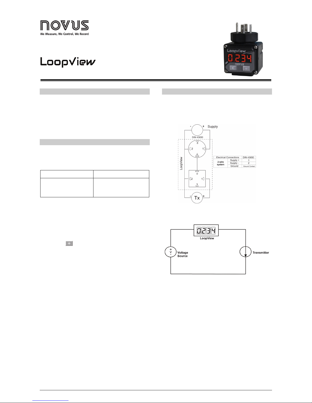
The indicator has standard EN 175301-803 (old DIN 43650) male
and female connectors. The indicator has internal protection against
polarity reversal of the power supply up to 60 mA.
Fig. 01 – Electrical connections
CONNECTION DIAGRAM
Fig. 02 – Connection diagram
RECOMMENDATIONS FOR THE INSTALLATION
Installation, operation, and maintenance must only be carried out by
qualified personnel and in accordance with the information provided
in this manual. Any deviation from these instructions will be the sole
responsibility of the client.
Normal safety precautions should be taken to avoid the possibility of
an accident occurring when operating under high pressure and/or
high temperature conditions.
Do not connect the power supply until the entire installation is
complete.
Page 2
LoopView-i
NOVUS AUTOMATION 2/3
MECHANICAL INSTALLATION
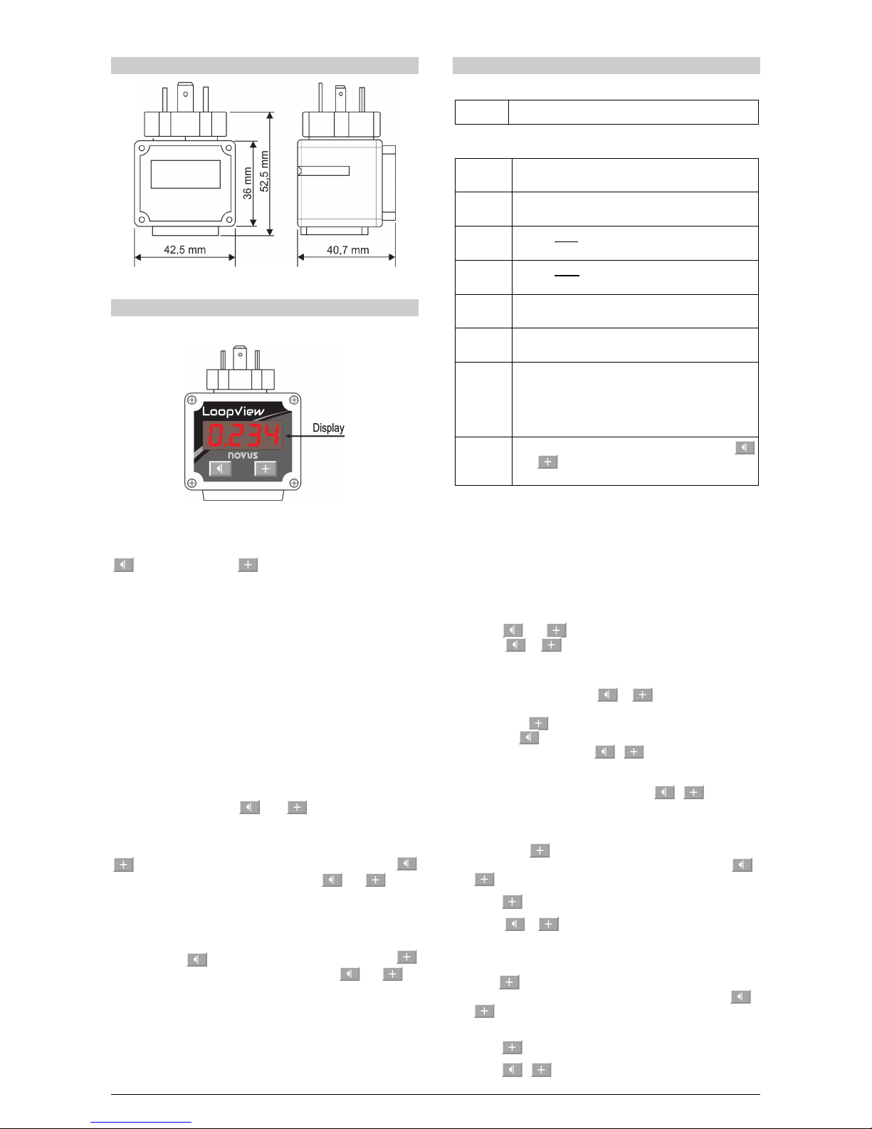
Fig. 03 – Dimensions
OPERATION
The controller’s front panel, with its parts, can be seen in the Fig. 04.
Fig. 04 – Indicator overview
Display: Shows the measured variable, the configuration parameters
and their values / conditions.
Decrement Key and Increment Key: Allow altering the
values of the parameters and accessing the indicator operation and
configuration cycles.
STARTUP
When the power is on, the indicator shows the value of the measured
process variable (PV). This is the Indication Screen.
In order for the indicator to operate properly, its parameters need to
be configured first. The configuration consists of the calibration and
definition of the programmable interval. The user must be aware of
the importance of each parameter and for each one determine a valid
condition.
The 2 cycles of parameters are:
• Operation
• Configuration
When pressing both keys ( and ) at the same time, the
indicator shows a screen where the device password must be
entered. After entering the password, the indicator will show the
configuration cycle. To advance the parameters of this cycle, use the
key with short touches. To rewind parameters, use the
key. To select the parameter, press both keys ( and ) at the
same time.
ACCESS PASSWORD
On the login screen, “
0000
” will show on the display, to enter a
value, press the , key, to change decimal places, press the
key, and to confirm the password, press both keys ( and ) at
the same time, the password is requested “66”.
PARAMETERS
OPERATION CYCLE
PV
PV Indication Screen. Value of measured variable.
CONFIGURATION CYCLE
Ad-L
AD-L
Statement of the minimum calibration signal at the
beginning of the range applied to the input (Low).
Ad-h
AD-H
Statement of the maximum calibration signal at the
end of the range applied at the input (High).
Ds-l
dS-L
Sets the lower value of the indication range (Low).
Ds-h
dS-H
Sets the upper value of the indication range (High).
-Dp-
dP
Sets the number of decimal places that will be shown
on the display.
Line
Line
Parameter that allows the user to make corrections to
the indicated PV value.
Filt
Filter
Digital Input Filter - Used to improve measured signal
(PV) stability. Adjustable between 0 and 9. At 0, it
means minimum filter and at 9, maximum filter. The
larger the filter,
the slower the measured value
response.
end
End
Final parameter that, when pressing both keys (
and )
at the same time, save the settings that
have been set by the user.
CALIBRATION
Following is the LoopView calibration procedure, which can be
divided into two steps, the unlocking and the calibration steps:
Unlock:
1. Connect LoopView into a 4-20 mA signal simulator. Vary it and
check if the indicator is powered up accordingly between 4 and
20 mA.
2. Press and keys simultaneously (from now on referred
to as / ) for 3 seconds and release them. Then
parameter
Lccy
will be displayed. It means we’ve accessed
Configuration Cycle.
3. At
Lccy
parameter click / in order to enter this
parameter’s adjustment. The current displayed value will be
0000
. The key increments values from 0 to 9 in a single
digit. The key shifts to the next digit to be adjusted. Define
value
0066
at it and press / to confirm.
Calibration:
4. Parameter
AD-L
will be displayed. Click / to enter this
parameter. A random number is displayed.
5. Simulate 4 mA in its input.
6. Single click key. At this moment LoopView reads input’s
current and determines it as its lower point (4 mA). Press /
to confirm and go back to
AD-L
.
7. Press key to shift to the next parameter,
AD-k
.
8. Press / to enter
AD-k
. A random number will be
displayed.
9. Simulate 20 mA in its input.
10. Click key. At this moment LoopView reads input’s current
and determines it as its superior point (20 mA). Press /
to confirm and go back to
AD-k
. Calibration is finished
here.
11. Press key until parameter
END
be displayed.
12. Press / to leave Configuration Cycle.
Page 3
LoopView-i
NOVUS AUTOMATION 3/3
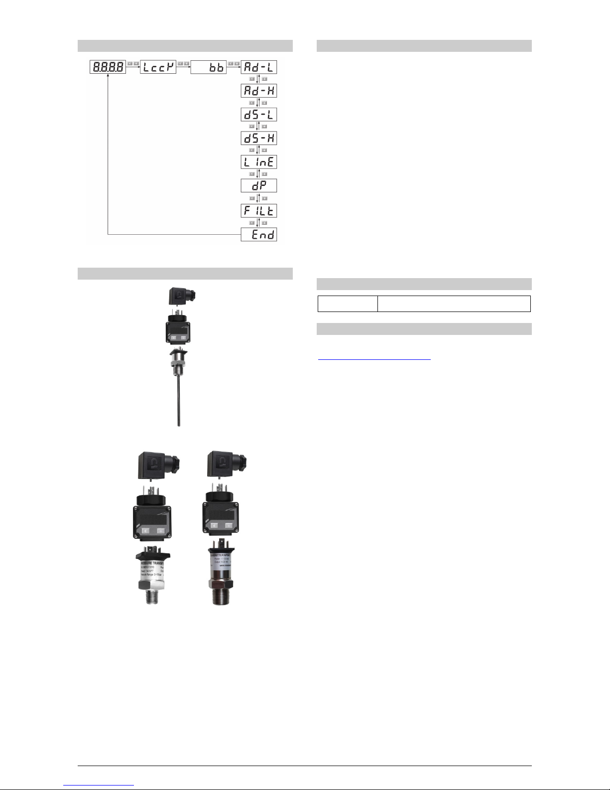
NAVIGATION LAYOUT
Fig. 05 – Navigation layout
APPLICATIONS
Fig. 06 – Coupled to temperature sensor
Fig. 07 – Coupled to pressure sensor
SPECIFICATIONS
DIMENSIONS: ............................................................ 65 x 45 x 45 mm
Approximate Weight: ...............................................................54 g
POWER SUPPLY: .............................................. 4-20 mA loop current
MAXIMUM LOOP CURRENT: ................................................... 60 mA
ENVIROMENTAL CONDITIONS:
Operating temperature: ............................................. -40 to 85 ºC
Temperature Drift: ............................................. < 0.003 % per ºC
INPUT: ..................................................................................... 4-20 mA
Internal Resolution:...................................... 65535 levels (16 bits)
Display Resolution: ...........................11998 levels (-1999 to 9999)
Accuracy: .......................................................... mA: 0.5 % of span
VOLTAGE DROP: ........................................................< 2.5 V to 4 mA
.......................................................................................< 3 V to 20 mA
ENCLOSURE: ......................................... ABS (Polyurethane Gasket)
PROTECTION: ............................................................ IP65, NEMA4X
CONNECTORS: ......Connector to input form A (DIN EN 175301-803)
START UP OPERATION: ……….Immediately after being energized.
IDENTIFICATION
LoopView-i Basic version
WARRANTY
Warranty conditions are available on our website
www.novusautomation.com/warranty
.
 Loading...