


Combined Hardness Tester
NOVOTEST T-UD3
Operating Manual
2018

NOVOTEST.ED.Т-UD3.000 OM
Operation Manual
Hardness Tester NOVOTEST T-UD3
Page. 2
CONTENT
1 DESCRIPTION AND OPERATION OF THE DEVICE AND ITS COMPONENTS ......................... 5
1.1 The purpose of the device ............................................................................................................... 5
1.2 Technical characteristics of the device ........................................................................................... 5
1.3 Standard delivery set ....................................................................................................................... 7
1.4 Purpose of the probes ...................................................................................................................... 7
1.5 Parts ................................................................................................................................................. 8
1.5.1 Ultrasonic Contact Impedance Probe U1 probe ..................................................................... 10
1.5.2 Leeb probe.............................................................................................................................. 10
1.6 Design and functioning ................................................................................................................. 11
1.6.1 Modes ..................................................................................................................................... 11
1.6.2 Leeb measurement principle (Leeb) ...................................................................................... 12
1.6.3 Ultrasonic Contact Impedance method .................................................................................. 12
1.7 Means of measurement, tools and accessories .............................................................................. 13
1.8 Marking and sealing ...................................................................................................................... 13
1.9 Packing .......................................................................................................................................... 13
2 INTENDED USE ................................................................................................................................. 14
2.1 Operational limitations .................................................................................................................. 14
2.2 Preparing the device for use .......................................................................................................... 14
2.2.1 Visual inspection .................................................................................................................... 14
2.2.2 Installing the batteries ............................................................................................................ 14
2.2.3 Connecting the Probe ............................................................................................................. 15
2.3 Using the device ............................................................................................................................ 15
2.3.1 Preparing the object of testing ............................................................................................... 15
2.3.2 Turning on .............................................................................................................................. 16
2.3.3 Charging the battery ............................................................................................................... 17
2.3.4 Measurements using Ultrasonic Contact Impedance Probe U1 probe ................................... 18
2.3.5 Measurements with the Rebound Leeb Probe ........................................................................ 21
2.3.6 Measurement modes .............................................................................................................. 24
2.3.7 Calibration .............................................................................................................................. 28
2.3.8 Settings ................................................................................................................................... 34
2.3.9 Archive ................................................................................................................................... 35
2.3.10 Memory card ........................................................................................................................ 36
2.3.11 Information........................................................................................................................... 36
2.3.12 Photo fixation of the measurements ..................................................................................... 37
2.3.13 Connecting to PC ................................................................................................................. 39
3 TECHNICAL MAINTENANCE OF THE PRODUCT AND ITS COMPONENTS ......................... 44
3.1 Security measures ......................................................................................................................... 44

NOVOTEST.ED.Т-UD3.000 OM
Operation Manual
Hardness Tester NOVOTEST T-UD3
Page. 3
3.2 Verification ................................................................................................................................... 44
3.2.1 Operations and verification means ......................................................................................... 44
3.2.2 Visual inspection .................................................................................................................... 45
3.2.3 Testing .................................................................................................................................... 45
3.2.4 Determination of the basic error of the instrument according to the HRC scale ................... 45
3.2.5 Determination of the basic error of the instrument on the scale HB ...................................... 46
3.2.6 Determination of the basic error of the instrument on the scale НV ..................................... 46
3.3 Warranty........................................................................................................................................ 47
3.3.1 Basic Warranty ....................................................................................................................... 47
3.3.2 Extended warranty ................................................................................................................. 47
3.3.3 Warranty for repaired or replaced parts ................................................................................. 47
All NOVOTEST brand spare parts installed during the warranty repair process are covered by the
NOVOTEST guarantee (until the end of the warranty period). ...................................................... 47
Spare parts replaced during warranty service under warranty are not returned to the owner of the
device. ............................................................................................................................................. 47
3.3.4 Wear parts .............................................................................................................................. 47
3.3.5 Duties of the owner ................................................................................................................ 48
3.3.6 Warranty Limitations ............................................................................................................. 48
3.3.7 Other cases not covered by the warranty ............................................................................... 49
3.3.8 Guarantees and consumer legislation ..................................................................................... 49
3.4 Maintenance of the device ............................................................................................................ 49
4 MAINTENANCE ................................................................................................................................ 52
5 STORAGE ........................................................................................................................................... 52
6 TRANSPORTATION .......................................................................................................................... 52
7 RESYCLING ....................................................................................................................................... 52

NOVOTEST.ED.Т-UD3.000 OM
Operation Manual
Hardness Tester NOVOTEST T-UD3
Page. 4
Caution!
Please read this manual carefully before using the NOVOTEST T-UD3 hardness tester.
This operating manual (hereinafter OM) includes general information intended to familiarize the
operating personnel with the operation and operating rules of the NOVOTEST T-UD3 hardness tester
(hereinafter referred to as the device or hardness tester). The document contains technical
characteristics, description of the design and principle of operation, as well as information necessary
for the correct use of the product. Before getting started, it is necessary to familiarize yourself with this
manual, since the operation of the device must be carried out by persons familiar with the principle of
operation and design of the device.
Proper and effective use of the hardness tester requires mandatory availability:
Methods of testing;
Conditions for carrying out the testing, according to the testing procedure;
Trained, and familiar with this OM user.
The enterprise-manufacturer reserves the right to make non-critical changes, without impairing
product specifications. These changes may not be mentioned in the text of this document.
The scope of delivery of the instrument includes the operational documentation including this
operating manual and the instrument passport.
The present OM applies to all modifications of the device: T-UD3, T-U3, T-D3.
Terms used in this manual:
Hardness testers for metals – are used for material hardness testing, without destroying its
structure.
Hardness – property of a material to resist the elastic and plastic deformation, or destruction when
an indenter of another material that is more solid and takes no deformation of its body incorporated
into the surface layer.
Indenter – An element of the device pressed into the material for measuring its hardness. For
manufacturing indenters diamonds, hard alloys, hardened steel are used.
Young's modulus (modulus of longitudinal elasticity) – Physical quantity characterizing the
properties of the material to resist tension, compression under elastic deformation.
Leeb method – To measure the hardness of the material, the elastic rebound method is used (The
ratio of the speed of the impact body before and after the impact is measured).
Ultrasonic Contact Impedance – Consists in measuring the degree of change (damping) of the
vibration frequency of the rod with the indenter at the end when inserted into the surface of the sample.
The softer is the metal the dipper indenter penetrates into it, the bigger the square of the contact and
the less it influences the rod oscillation frequency (ultrasonic).
Kalman filter – An effective recursive filter that estimates the vector of a dynamic system state
using a series of incomplete and noisy measurements.
Median Filter – One type of digital filter, widely used in digital signal processing to reduce noise.
The median filter is non-linear FIR filter. Median filtering is an efficient procedure for processing
signals subject to impulse noise.

NOVOTEST.ED.Т-UD3.000 OM
Operation Manual
Hardness Tester NOVOTEST T-UD3
Page. 5
1 DESCRIPTION AND OPERATION OF THE DEVICE AND ITS COMPONENTS
1.1 The purpose of the device
The device is designed to measure hardness of:
metals and alloys on the Rockwell (HRC), Brinell (HB) and Vickers (HV), Leeb (HL),
Shore (HS) hardness scales and others.;
surface layer of metal subjected to fusing, spraying, mechanical, thermal and other types of
metal surface treatment;
cast iron, stainless steels and non-ferrous alloys, using the calibration mode on non-
standard hardness test blocks;
measuring of the tensile strength (v) for stretching products from carbonaceous steels of
the pearlite class by automatic recalculation from the Brinell hardness scale (HB).
The Hardness Tester allows instant analysis of the hardness of the product directly at the site of
operation or production of the product in workshop, laboratory and field conditions, for example, in
machine building, metallurgy, power engineering, shipbuilding and railway transport, aerospace and
oil and gas industry, repair and installation and service organizations etc.
The objects of measurement can be: pressure vessels for various purposes (reactors, steam
generators, collectors, boiler drums, gas holders, etc.), rotors of turbines and generators, pipelines,
rolls, crankshafts, gears, parts of various vehicles, industrial semi-finished products (castings,
Forgings, sheets), etc. Also, the hardness tester can be used for:
assessing the stability of technological processes (product processing, welding, etc.);
diagnostics of equipment, in order to evaluate its residual safe resource (control of
hardness of pipelines, boilers, etc.);
assessing the quality of performed repairs;
heat treatment quality evaluation.
1.2 Technical characteristics of the device
The NOVOTEST T-UD3 hardness tester is a portable device made in an impact-resistant housing
(with a special protective silicone bumper-case for complicated operating conditions) inside which a
board with electronic components and accumulators are placed. The main characteristics of the device
are presented in Table. 1.1, Table. 1.2 shows the ranges of measurements, and characteristics of probes
in Table. 1.3.
Table 1.1 - The main characteristics of the device
Overall dimensions, mm
180х80х35
Powered by three NiMH batteries or AA batteries
each 1,2 V
Power supply current, not more than, mA
100
Time of continuous operation, not less than, h
10
Weight of electronic unit with batteries, not more than, g
250
Operating temperature range, ° С
from -20 to + 40
Humidity, not more,%
from 30 to 80

NOVOTEST.ED.Т-UD3.000 OM
Operation Manual
Hardness Tester NOVOTEST T-UD3
Page. 6
Table 1.2 - Measurement range and limits of the basic permissible error
Hardness scale
Measurement range
Measurement error
U1
Leeb
Rockwell, HRC
From 20 to 70
±2
±2
Brinell, HB
from 90 to 150
±10
±10
Brinell, HB
from 150 to 650
±15
Vickers, HV
from 240 to 500
±15
±15
Vickers, HV
from 500 to 940
±20
Leeb, HL
from 300 to 800
–
±15
Shore, HS
from 30 to 100
Is determined when markup
Strength limit σv (reference), Мpa
from 370 to 1500
Is determined when markup
Table 1.3 - Characteristics of probes
Probe Type
U1 (98 N)
U1 (50 N)
U1 (10 N)
Leeb
Overall dimensions, mm
Ø30х140
Ø30х140
Ø30х140
Ø20х145
Weight, g, not more than
250
250
250
130
Roughness of the measured surface, Ra
2,5
2,5
2,5
3,2
Radius of curvature of the measured
surface, mm
5 5 5
10
Weight of the controlled product, not less
than, kg
0,1
0,1
0,1
5
Thickness of the controlled product, not
less than, mm
1 1 1
12
Load, kgf
10 5 1
-
The device corresponds to: ASTM A956 “Standard Test Method for Leeb Hardness Testing of
Steel Products”; ASTM A 1038 “Standard Test Method for Portable Hardness Testing by the
Ultrasonic Contact Impedance Method”.
MTBF
Mean time between failures of the device without taking into account the reliability factor of the
probes is not less than 6000 h.
Service time
The total average service life of the device is not less than 10 years.
The criteria of decommissioning of the device - economic inexpediency of restoring the operable state
of the components of the instrument by repairing.

NOVOTEST.ED.Т-UD3.000 OM
Operation Manual
Hardness Tester NOVOTEST T-UD3
Page. 7
1.3 Standard delivery set
Electronic Unit ........................................................................................................................ 1 pc.
Rebound Leeb Probe ............................................................. Availability - according to the order
Ultrasonic Contact Impedance Probe U1 (98 N) .................. Availability - according to the order
Ultrasonic Contact Impedance Probe U1 (50 N) .................. Availability - according to the order
Ultrasonic Contact Impedance Probe U1 (10 N) .................. Availability - according to the order
Rechargeable battery ............................................................................................................... 3 pc.
Charger .................................................................................................................................... 1 pc.
USB cable for PC .................................................................................................................... 1 pc.
Case ......................................................................................................................................... 1 pc.
Operating manual NOVOTEST.T-UD3.000 OM ................................................................... 1 pc.
Passport NOVOTEST.T-UD3.000 PS ................................................................................... 1 pc.
Additional equipment:
Hardness test blocks (HRC, HB, HV, HLD, etc.) .................................................. If ordered
Cordless grinder ...................................................................................................... If ordered
* At the request of the customer, the delivery kit can be expanded with additional equipment or
parts. The exact information about the delivery set is indicated in the passport of the device.
1.4 Purpose of the probes
The Rebound Leeb Probe (Figure 1.1, Rebound Leeb Probe) – purposed for hardness
measurement by dynamic method. It is intended for measuring hardness of large-sized objects, and
also coarse-grained materials.
The Ultrasonic Contact Impedance Probe U1 (Figure 1.1, Contact Impedance Probe U1) Measurement of hardness by Ultrasonic Contact Impedance method. The use of a diamond indenter
allows the probe to be mounted precisely at any tiny point, and leaves a small-size imprint, making the
measurement of the U1 the least destructive.
The probe is perfectly suited for the following tasks: measuring the hardness of complex shapes,
fine-grained materials, heat-treated materials, thin layers and coatings, surface hardened parts, thinwalled pipes, small parts, etc.
Table 1.4 shows the characteristics of the UCI U1 type probes.
Figure 1.1 - Types of probes

NOVOTEST.ED.Т-UD3.000 OM
Operation Manual
Hardness Tester NOVOTEST T-UD3
Page. 8
Table 1.4 - Features and applications of UCI U1 probe type
Model
Load
Features
Main applications
UCI U1
(98 N)
98 N
(10 kgf)
The main type of probe for
solving most problems of
hardness measurement. 10 kg
load is to be applied for
measurement (set automatically
by the probe). Low requirements
for surface cleanliness.
Heat-treated and cemented details.
Measuring in grooves, on teeth, on
radius surfaces.
Measurement on the blades, on the
internal surface of the pipes,
openings.
UCI U1
(50 N)
50 N
(5 kgf)
The main probe type for the most
tasks of hardness measurement. 5
kg. load is to be applied for
measurement (automatically
controled by the probe). Average
surface cleannes requirements.
Heat-treated and cemented parts, for
example, shafts, turbines, gears,
teeth, welds, heat affected zones.
Measuring in grooves, on teeth, in
grooves, on radius surfaces.
Measurement on the blades, on the
internal surface of the pipes,
openings.
UCI U1
(10 N)
10 N
(1 kgf)
The reduced load probe is
designed to measure the hardness
of material with increased
requirements to the print size
(polished surfaces), to measure
the hardness of surface hardened
layers. 1 kg. load is to be applied
for measurement (automatically
controled by the probe).
More sensible to the surface
cleanliness, in comparison with
U1 (50 N).
Nitrided and cemented surface
layers of molds, stamps, stamps,
thin-walled parts.
Bearings, lateral surfaces of saws
teeth.
Measurement of hardness of
hardening coatings.
Measurement on the blades, on the
inner surface of the pipes, inside the
holes.
1.5 Parts
The device consists of an electronic unit made of impact-resistant ABS plastic and placed into a
protective silicone bumper, as well as connected probes. The detachable connection is located on the
upper end surface of the housing; there is also a mini USB connector, which is used to connect the
device to PC or to charge the batteries. The control keyboard is located on the front panel, which also
houses a contrasting color LCD / TFT display. In the lower rear part of the device under the cover,
fixed with the threaded connection with the help of two screws, there is a battery compartment in
which the batteries are installed (Figure 1.2.). In Fig. 1.3, it shows the control keyboard of the device.
NOVOTEST.ED.Т-UD3.000 OM
Operation Manual
Hardness Tester NOVOTEST T-UD3
Page. 9
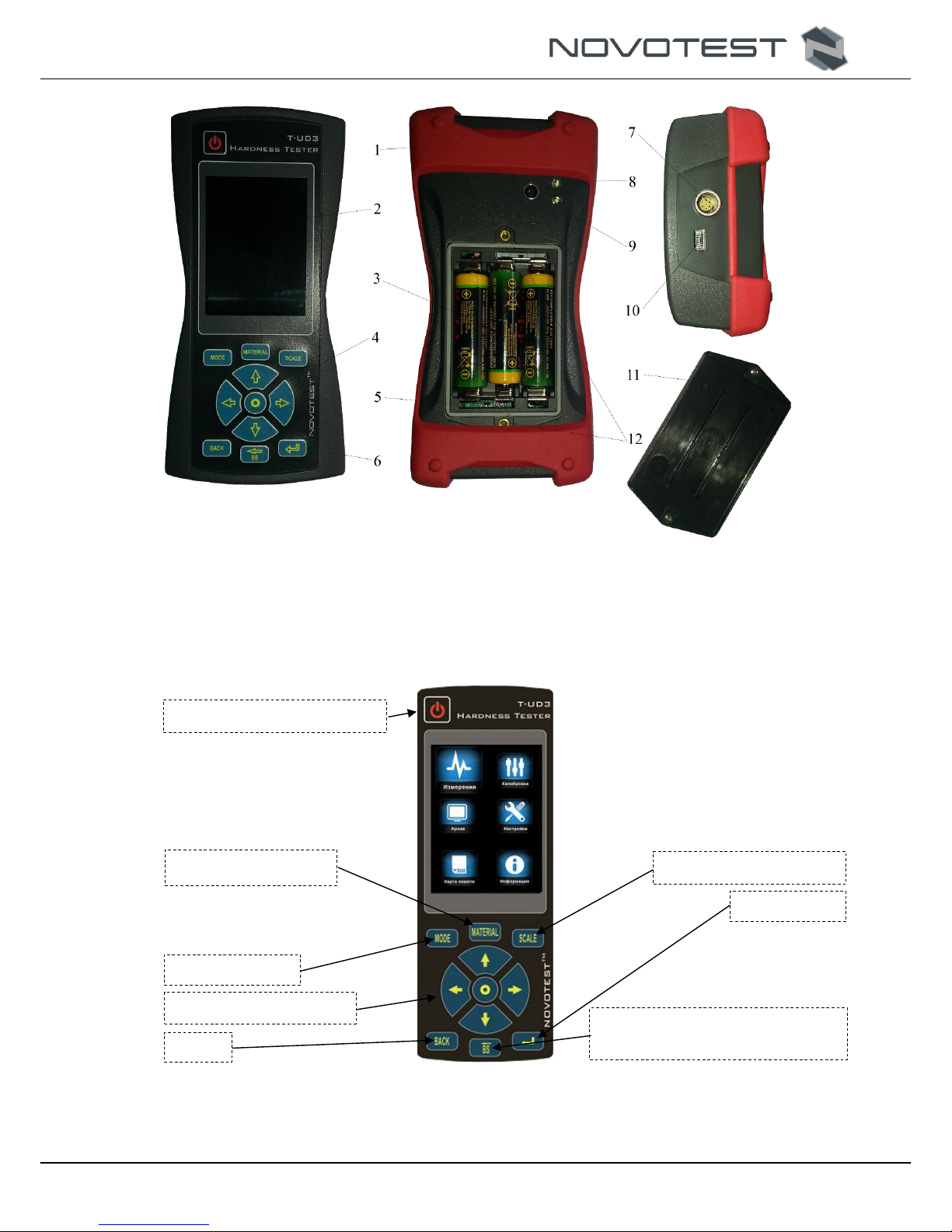
1– bumper; 2 – LCD/TFT color contrast display; 3 – NiMH battery; 4 – control keyboard; 5 – battery
compartment; 6 – electronic unit; 7 – probe socket; 8 – flash light; 9 – photo camera; 10 – mini USB
socket; 11 – cover; 12 – cover securing with threaded connections.
Figure 1.2 - Hardness meter NOVOTEST T-UD3
Figure 1.3 - Control buttons and their functional purpose
On/Off button
Material selection
Mode selection
Navigation keys
Back
Scale mode selection
Enter
Backspace (back /delete one
position)
NOVOTEST.ED.Т-UD3.000 OM
Operation Manual
Hardness Tester NOVOTEST T-UD3
Page. 10
1.5.1 Ultrasonic Contact Impedance Probe U1 probe
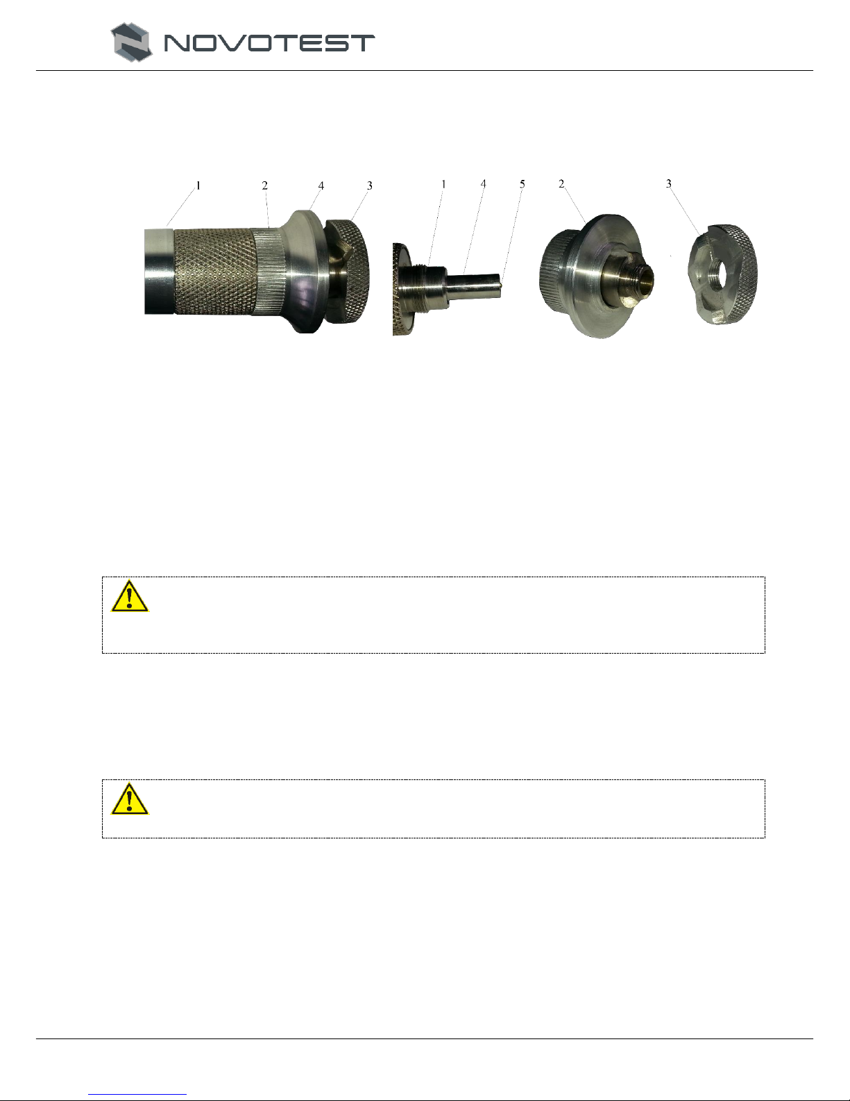
The construction of the probe is shown in Fig. 1.4. The probe has a special removable collapsible
head with a double-sided thrust washer. The thrust washer provides the convenience of positioning the
probe onto the product and pressing during the measurement.
1 – housing; 2 – removable collapsible nozzle; 1 – housing; 2 – removable collapsible nozzle;
3 – removable double sided thrust washer; 3 – removable double sided thrust washer;
4 – support platform. 4 – centering pipe; 5 – diamond tip.
Figure 1.4 - Appearance of the Ultrasonic Contact Impedance Probe U1
One side of the washer is flat; the other has prismatic grooves designed for the convenience of
measuring hardness on cylindrical products of different diameters. The probe with the removed washer
is used for carrying out of measurement of hardness in narrow and hardly accessible places.
To measure hardness on flat surfaces, the washer on the probe head should be installed flat to the
surface of the product, and to measure the hardness on the cylindrical surfaces, the washer on the
probe head should be installed with a side with prismatic grooves to the product.
Caution!
To ensure a better smoothness of the collapsible detachable nozzles, they are individually grounded to
each probe. Replacement of probe tips is not allowed.
1.5.2 Leeb probe
The Leeb probe has a built-in mechanism for charging the spring, which is the most ergonomic
and convenient to work with. Spring charging is provided by moving the upper part of the probe
housing downwards, after which the probe can be installed on the controlled object and measurement
can be done.
Caution!
It is forbidden to discharge the trigger of the Leeb probe “in the air”.

NOVOTEST.ED.Т-UD3.000 OM
Operation Manual
Hardness Tester NOVOTEST T-UD3
Page. 11
Figure 1.5 - The appearance of the Leeb probe
1.6 Design and functioning
The principle of operation of the hardness tester depends on the type of the connected probe.
When using the Leeb probe, the hardness is measured by the dynamic method of Leeb, and when
using the UCI probe - by the ultrasonic contact impedance method.
The dynamic method of measuring hardness is used to control:
hardness of objects weighing more than 5 kg and wall thickness of more than 10 mm;
hardness on solid products, products with coarse-grained structure, forged and cast
products;
hardness, if minimal surface preparation is required.
Ultrasonic contact impedance -resonance method for measuring hardness is used to measure:
hardness of objects with low mass (from 0,1 kg) and wall thickness (over 1 mm);
hardness on products with a glossy surface (if the minimum print size is required);
hardness of the surface hardened layer at the inspection site.
1.6.1 Modes
The hardness tester works in the following modes:
1. <MEASUREMENTS>:
Main scales mode (HRC, HRB, HB, HV, HS, HL, MPA);
User scales mode (U1, U2, U3);
A mode of measurement of hardness of basic materials (steel, alloy steel, stainless
steel, gray cast iron, high-strength cast iron (<CHARG>), aluminum, brass, bronze,
copper);
A mode of measurement of hardness of user materials (<USER 1>, <USER 2>);;
<CHART> mode;
<HISTOGRAM> mode;
<STATISTIC> mode;
<INTELLECT> mode;
<SIGNAL> mode.
2. <CALIBRATION>:
One point;
Three points.
3. <ARCHIVE>:
Saved measurements view.
4. <SETTINGS>:
<DATE>;
Impact Body
Inductive coil
Housing
Trigger
Plug
Charger

NOVOTEST.ED.Т-UD3.000 OM
Operation Manual
Hardness Tester NOVOTEST T-UD3
Page. 12
<TIME>;
<LANGUAGE>;
<PHOTO>;
<BRIGHTNES>;
<PALETTE>;
<SOUND>;
<RESULT>;
<VOLUME>;
<AUTO OFF>;
<RETRO>;
<FLASH>;
<TOLERANCE>;
<FILTER>;
<FILTER MODE>.
5. <MEMORY CARD>:
<SAVE>;
<LOAD>;
<CLEAR>.
6. <INFORMATION>:
About dealers;
About the device.
7. Two-way communication with PC:
Data transfer;
Transfer of calibration settings;
Interface change.
1.6.2 Leeb measurement principle (Leeb)
The dynamic principle probe (rebound method) is a separately executed device connected to the
electronic unit by means of a cable.
The principle of measuring hardness is based on the determination of the ratio of the velocities of
impact and rebound of the striker inside the probe. Carbide ball is located at the end of the impact
body, directly in contacting with the material at the time of impact. Inside of the impact body is a
permanent magnet. The striker, after pressing the trigger button, is ejected onto the surface to be
measured by a pre-charged spring. While this, the striker moves inside the inductor coil and, with its
magnetic field, induces an electromotive force (EMF) in it. The signal from the output of the induction
coil is fed to the input of the electronic unit, where it is converted into a hardness value of the selected
scale and displayed.
This method is particularly suitable for hardness measurements on solid products, coarse-grained
products, forged and cast products.
The design of the dynamic probe allows user to make more measurements per unit of time, and
working with it does not require special skills, such as with an UCI probe.
1.6.3 Ultrasonic Contact Impedance method
Ultrasonic probe (UCI ultrasonic contact impedance method) is a separately executed device
connected to an electronic unit by means of the cable.
The probe basically uses a steel rod with a diamond pyramid at the end, which is an Acoustic
Resonator (Oscillating Rod) of the built-in self-oscillator of ultrasonic frequency. When the diamond
pyramid is introduced into the tested object under the action of the fixed load of the calibrated spring,
the resonant frequency of the resonator changes, determined by the hardness of the material. The
relative change in the frequency of the resonator is converted by the electronic unit into the hardness
value basing on the selected scale and displayed.

NOVOTEST.ED.Т-UD3.000 OM
Operation Manual
Hardness Tester NOVOTEST T-UD3
Page. 13
This method is suitable for hardness measurements on products of various weight and thickness,
and especially on finished products with a glossy surface, since it leaves a minimally visible imprint
after measurements.
The design of the ultrasonic probe makes it possible to carry out measurements in hard-to-reach
places (for example, the surface of gear teeth, etc.), as well as on thin-walled structures (eg. pipelines,
etc.) that can not be measured dynamically by the probe.
It should be taken into account that the result of the measurement by the UCI method depends on
the Young's modulus of the tested product.
1.7 Means of measurement, tools and accessories
The efficiency of the device is evaluated by checking the measurement of hardness on the
reference hardness test blocks, reference hardness blocks should be grounded to the grinding plate
weighing not less than 5 kg through a layer of grease. Mismatch readings must not exceed the
permissible error (Table. 1.2). If the permissible error is exceeded, calibrate the instrument in
accordance with 2.3.7.
The manufacturer should make adjustment and tuning of the device in the case of faults.
1.8 Marking and sealing
On the front panel of the device is a symbol of the device with the trademark of the manufacturer.
On the rear panel, under the battery compartment cover the serial number is printed.
1.9 Packing
The electronic unit and the probe are delivered in a package (case), excluding their damage during
transportation.
To avoid mechanical damage to the cable and connectors of the device, it is necessary to
disconnect the sensor from the device before packing it into the package.

NOVOTEST.ED.Т-UD3.000 OM
Operation Manual
Hardness Tester NOVOTEST T-UD3
Page. 14
2 INTENDED USE
2.1 Operational limitations
Operation of the device should be carried out under the influence of factors and taking into
account the parameters of the monitored objects in accordance with the specified technical
characteristics, and the device must be used within its technical characteristics.
Only qualified personal, familiar with the operation manual is allowed to use with this device.
After transporting the device to the place of operation at a negative ambient temperature and
placing it into a room with a positive temperature, it is necessary to keep the product in its packaging
for at least 6 hours in order to avoid failure due to condensation of moisture.
2.2 Preparing the device for use
2.2.1 Visual inspection
Carry out visual external inspection of the device; make sure that there are no mechanical
damages to the electronic unit, the probe, the connector and the connecting cable.
2.2.2 Installing the batteries
Install the batteries into the battery compartment by unscrewing the two fixing screws and
removing the battery cover. Batteries are to be installed according to the polarity indicated on the
device (Figure 2.1). Close the battery compartment cover and screw in the screws.
Figure 2.1 - Installing the batteries

NOVOTEST.ED.Т-UD3.000 OM
Operation Manual
Hardness Tester NOVOTEST T-UD3
Page. 15
2.2.3 Connecting the Probe
Using the connecting cable connect the probe to be used to the probe socket on the electronic unit.
Connect the connecting cable making sure that the red dot on the plug and socket are in line (Figure
2.2).
Figure 2.2 - Connecting the probe
2.3 Using the device
2.3.1 Preparing the object of testing
Prepare the needed surface area of the material, removing moisture, contamination (oil, dust, etc.),
grease, scale, oxide film, and rust from it. Grind it with a grinder or sandpaper and wipe the ragged
surface.
The roughness and radius of curvature of the measured surface, as well as the weight and
dimensional characteristics of the product, should correspond to the parameters specified in the
technical characteristics of the hardness tester (Table 1.3), consider the type of probe (UCI or
dynamic) used for the measurement.
The results of measurements by the UCI method are affected not only by the properties of the
metal during plastic deformation, but also by the Young's modulus (modulus of elasticity). It entails
the need to adjust the instrument when working with products that have the Young's modulus different
from the Young's modulus of structural and carbon steels.
To determine the additional error presence, compare the results of measurements with the
measurements of the hardness of the static measurement principle. If the difference in the results does
not exceed the error of the instrument, it means that it is possible to carry out measurements on the
characteristic written in the memory of the instrument upon delivery. If the measurement error exceeds
the required accuracy, a two-point or one-point calibration of the device on the product or sample (see
2.3.7) is necessary.
If the product or measure of hardness does not meet the requirements of Table. 1.3 (mass and / or
thickness), the instrument will make measurements with additional error. It will be as big, as the

NOVOTEST.ED.Т-UD3.000 OM
Operation Manual
Hardness Tester NOVOTEST T-UD3
Page. 16
discrepancy from these requirements is. The sign of the additional error may be, either positive or
negative, depending on the specific conditions.
The reason for the additional error emergence is the parasitic oscillation at the point of contact of the
indenter with the material at the moment of measurement. This is due to the vibration of the whole
product, if its weight is low, either because of deflection product if its thickness is small.
To determine the presence of additional error compare the measurement results with the results of
measurements of hardness using a bench hardness tester.
There are three methods to eliminate the additional errors.
The first method – to make the one-point or two-point correction of the current user setting in
accordance with clause 2.3.7. It is used if an additional error of not more than 15%, and the results in a
series of measurements are stable.
The second method – by eliminating parasitic oscillations gripping articles in a vise (clutches mass
should be clearly greater weight than the indicated in Table 1.3.). To prevent damage to the product is
allowed to use on overhead jaws of a softer metal vice.
The third method (recommended) – eliminating parasitic oscillations by grounding the object to a
massive polished plate. The plate should have roughness Ra not greater than 0.4 microns, obviously
greater weight than indicated in Table 1.3, non-flatness not less than 0.005 mm, a Young's modulus of
the material from which the plate is made should be close to the Young's modulus of the product. The
lower portion of the object is to be plane-polished with a roughness Ra not greater than 0.4 microns
and flatness no more than 0,005 mm. To install the product on the plate on its support surface a thin
layer of lubricant to be used. The product is to be grinded to the plate surface so that between the
surfaces and plates were no stains of even small air gaps. Grind must be tight enough so that the
product and the plate form a single monolithic.
Also, the cause of the error may be fingerprints of different depths. The values of these depths
may differ, depending on the measured hardness (Table 2.1.). It is recommended to measure the
hardness of the layer that is 20 times greater than the indentation depth. For the reasons stated above,
the measurement result is influenced by the properties of the surface layer. The depth of penetration of
the indenter into the material is substantially smaller than with the instrument of the static type: Brinell
and Rockwell. This can lead to misalignment of the measurement results in the case of hardening,
decarbonized layer, burn marks, and martensitic spots.
Table 2.1 - The depth of the imprints on the material surface in millimeters
Probe type
100НВ
187НВ
400НВ
60,7HRC
Leeb
0,039
0,028
0,021
0,018
UCI (98 N)
0,098
0,081
0,052
0,036
UCI (50 N)
0,070
0,056
0,038
0,025
UCI (10 N)
0,031
0,025
0,017
0,011
Hardening can be formed in the surface layer after the turning and milling and rough polishing.
The softer the metal, the greater the difference between the hardness of the top layer and the inside.
Decarbonized layer with low hardness is formed by the high-temperature heat treatment. This may
be hardening, normalization, hot rolling, forging, etc. The thickness of this layer is typically less than
0.2 mm.
When heat treated steels with good hardenability by the average hardness in the surface due to
overheating may occur martensitic stains with high hardness.
2.3.2 Turning on
Turn on the device by long pressing the key < > on the control panel until the short splash
screen on the display (Fig. 2.3).

NOVOTEST.ED.Т-UD3.000 OM
Operation Manual
Hardness Tester NOVOTEST T-UD3
Page. 17
Figure 2.3 – splash screen
After this, the device switches to the main menu (Fig. 2.4), or in the <Measuring> mode (if the
probe is connected).
Figure 2.4 - Main Menu
From the Main Menu the user can access:
1. <MEASURING>;
2. <CALIBRATION>;
3. <ARCHIVE>;
4. <SETTINGS>;
5. <MEMORY CARD>;
6. <INFORMATION>.
After entering the selected sections, except the <Information>, the display is divided into two
areas: the main area and information area (upper part of the display).
In the main area Workspace section is located, and in the information provides information on the
batteries charge, connecting the device to your PC, SD card presence as well as the current time.
Before using the device, make sure that the batteries has enough power. Fully stocked LED
(green) indicates that the battery is charged to 100%. In the absence or deficiency of charge volume
(red), charge the battery charging from a charger or by connecting the device to PC.
Long press on the button < > makes the device to shut down.
2.3.3 Charging the battery
To charge the battery, the user must plug the power supply included with the hardness tester to the
power connector located on the upper end of the housing. During charging, the device can be used.

NOVOTEST.ED.Т-UD3.000 OM
Operation Manual
Hardness Tester NOVOTEST T-UD3
Page. 18
Battery full time - 14 hours. Watch the device during charging. Also, the device can be charged by
connecting it to a PC.
If not using the device charge the batteries at least once per two month to avoid batteries from
failure.
2.3.4 Measurements using Ultrasonic Contact Impedance Probe U1 probe
RESTRICTION: limited use for measuring articles with a coarse-grained structure (e.g., iron)
or a mass of less than 100 grams, or less than 1 mm thick! Typically, such
products must be grounded to a massive polished plate.
1. Before measurements, it is necessary to prepare the surface according to p. 2.3.1.
2. Plug the UCI probe.
3. Turn the device on by long pressing < >.
4. Since the probe is already connected, the device immediately goes to the
<MEASUREMENTS> section (figure 2.5).
Figure 2.5 – <MEASURING> section
5. Choice the needed hardness scale, press < > to assess the choice menu (fig. 2.6), than
select the needed scale with < > and < > keys (the Rockwell C (HRC), Brinell
(HB), Vickers (HV), Rockwell B (HRB), Shore (HS), Leeb (HL), the measurement of tensile
strength (v), Tensile products of carbon steel pearlite (MPA), a user (U1, U2, U3)).
Figure 2.6 - Selecting the hardness scales
User calibration presence
Diamond indenter state
(Ready to work)
Mode
Scale
Material

NOVOTEST.ED.Т-UD3.000 OM
Operation Manual
Hardness Tester NOVOTEST T-UD3
Page. 19
6. Select the material that is going to be tested. By pressing < > open the selection menu
(fig. 2.7), with the keys < > and < > select the desired material (steel, alloy steel,
stainless steel, gray iron, ductile iron (< Nodular Iron>), aluminum, brass, bronze, copper, a
user (<USER. 1>, <USER. 2>).
Note: On supply the UCI probe only has records for steel. The rest of material may be
recorded by user.
Figure 2.7 – Material selection
7. Select a desired measurement mode (see. P. 2.3.6), using < > open mode selection menu
(fig. 2.8), using keys < > and < > select the needed mode (<GRAPH>,
<HISTOGRAM>, <STATISTICS>, <INTELLECTUAL>, <SIGNAL>).
Figure 2.8 - Selecting the metering mode
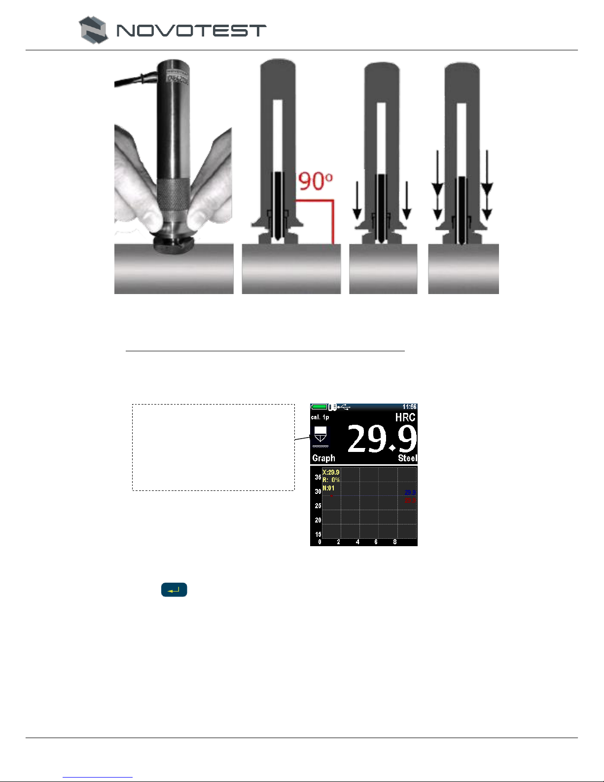
8. Place the probe thrust washer on the sample surface, keeping it in the area of support platform
as shown in Fig. 2.9. A. Pushing on the support platform with two hands draw diamond tip of
the probe vertically to the sample until it touch the surface (Fig. 2.9, B) and non-stop, gently
(approximately while 0.5 seconds), with a pressing force (5 kg if probe UCI (50N) ) press the
diamond tip into the surface of the metal preventing rocking (Fig. 2.9 C).
Caution!
Avoid abrupt depression, because it can lead to exceeding the maximum permissible value of the error
and cleavage the diamond indenter.
NOVOTEST.ED.Т-UD3.000 OM
Operation Manual
Hardness Tester NOVOTEST T-UD3
Page. 20
A B C
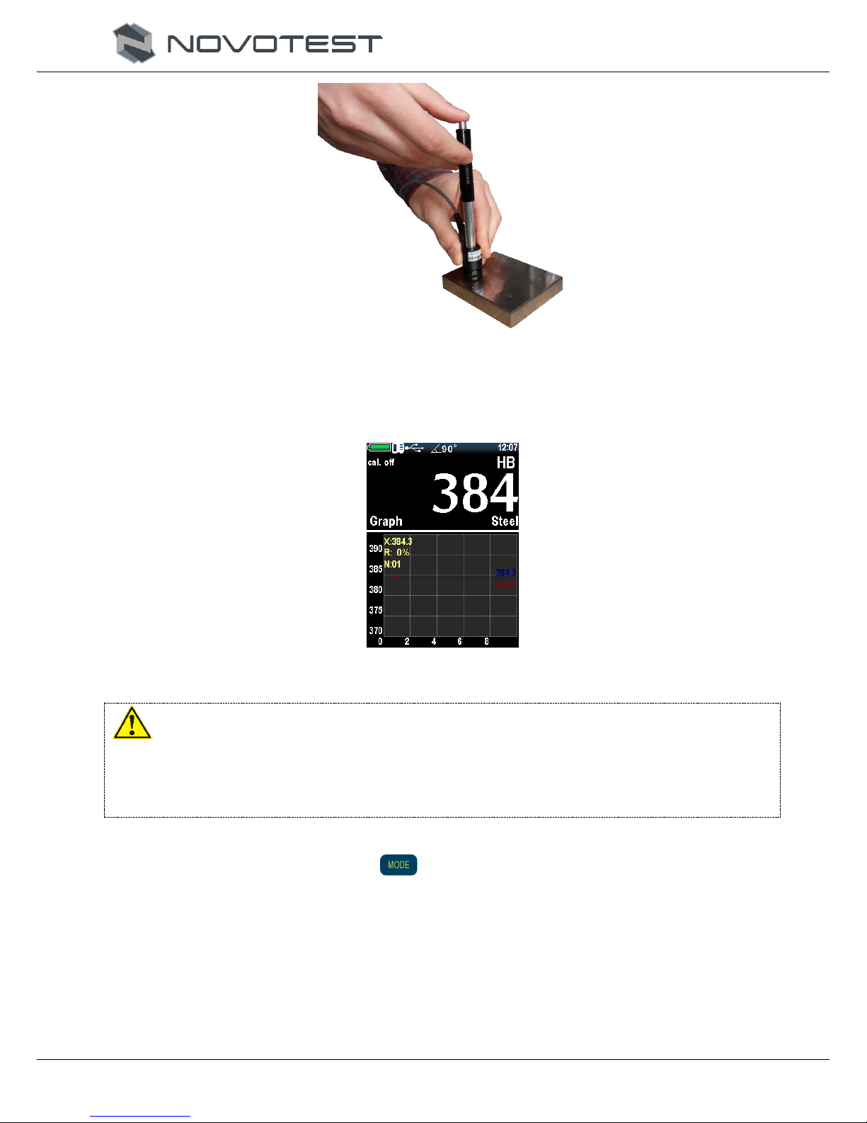
Figure 2.5 – Measuring with UCI U1 probe
Note: The load is set by the built in the probe controlled load spring.
9. The display shows the value of hardness (Fig. 2.10). The measurement result is displayed on
the display until the next measurement.
Figure 2.10 - Display after measurement
10. After the measurements the user can save measurement (set of measurements) into archive by
pressing < > key (ENTER).
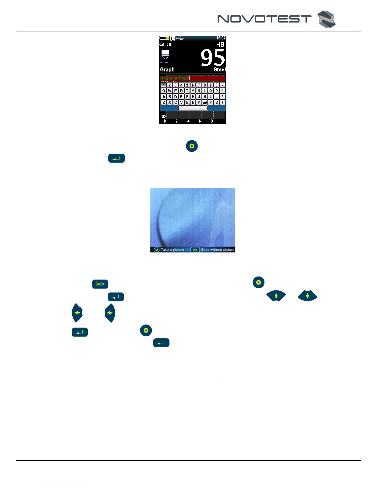
11. A keyboard will appear on the display to enter the measurement (set of measurements) (Fig.
2.11).
This symbol shows that the
diamond indenter is in touch
with the tested object or the
device is not ready for the next
measurement
NOVOTEST.ED.Т-UD3.000 OM
Operation Manual
Hardness Tester NOVOTEST T-UD3
Page. 21
Figure 2.11 - Entering a name for the stored dimension
12. Target on the needed symbol and press < > to select it. After entering the saving result
name press < > key to save.
13. If <PHOTO> mode is set on (See P 2.3.12 for the details about the <PHOTO> mode), than the
device will offer you to <TAKE PICTURE> or <SAVE WITHOUT PHOTO> (Fig. 2.12).
Figure 2.12 - Mode <PHOTO>
14. Press < > key to save the measurements without photo, or < > to take picture.
15. Than press < > key to save photo. Than, using navigation keys < >, < >, <
> and < > put the marker on the point, where the measurement took place, press <
> key to save, or < > to put another marker on the picture. Confirm saving of the
pointed marker by pressing < > key – saves picture without prompting to add another
marker.
Note: The distance between the fingerprint center and the edge of the specimen or adjacent
indentation should be at least 2.5 diagonal length fingerprint.
2.3.5 Measurements with the Rebound Leeb Probe
RESTRICTION: limited use for measuring objects with weight less than 5 kg or thickness less
than 10 mm without additional preparation! Typically, such products must
be grind to a massive polished plate.
1. Prepare the controlled object before taking measurements as in P. 2.3.1.
2. Plug in the Leeb probe.

NOVOTEST.ED.Т-UD3.000 OM
Operation Manual
Hardness Tester NOVOTEST T-UD3
Page. 22
3. Turn the device on by long press the < > key.
4. Since the probe is connected the device goes to the <MEASUREMENT> mode at once (Fig.
2.13).
Figure 2.13 - <MEASUREMENT> SECTION
5. Select the needed hardness scale, press < > to assess the choice menu (fig. 2.13), than
select the needed scale with < > and < > keys (the Rockwell C (HRC), Brinell
(HB), Vickers (HV), Rockwell B (HRB), Shore (HS), Leeb (HL), the measurement of tensile
strength (v) Tensile products of carbon steel pearlite (MPA), user’s (U1, U2, U3)).
6. Select the desired material. By pressing < > open the selection menu (fig. 2.13), with the
keys < > and < > select the desired material (steel, alloy steel, stainless steel, gray
iron, ductile iron (<NODULAR. IRON>) aluminum, brass, bronze, copper, a user (<USER 1>,
<USER. 2>)).
7. Select a desired measurement mode, using < > open mode selection menu, using keys <
> and < > select the needed mode (<GRAP> <HISTOGRAM>,
<STATISTICS>, <INTELLECTUAL>, <SIGNAL>).
8. Press keys < > or < >, to set the measurement angle. The angle is shown at the
top of the display (Fig. 2.14). Default angle 0 degree corresponds to vertical position of the
probe, where trigger button looks up.
Figure 2.14 – Setting the angle
User calibration presence
The angle of
measurement
Mode
Scale
Material

NOVOTEST.ED.Т-UD3.000 OM
Operation Manual
Hardness Tester NOVOTEST T-UD3
Page. 23
9. Set the probe onto the surface of the material at the zone of control (Fig. 2.15).
Figure 2.15 – Setting the probe
10. Hold the bottom part of the probe housing with one hand, and charge the spring of the probe
by mowing the upper part of the housing down with the other hand. (Fig. 2.16).
Figure 2.16 – Charging the spring of the probe
11. Smoothly push the trigger button on the top of the probe (Fig. 2.17). Make sure that the probe
does not move and secured to the surface of the controlled zone.
NOVOTEST.ED.Т-UD3.000 OM
Operation Manual
Hardness Tester NOVOTEST T-UD3
Page. 24
Fi 2.17 – Pushing the trigger button of the probe
12. After pushing the trigger button and the Impact Body hits the surface the measured hardness
value will appear on the display. (Fig. 2.18).
Figure 2.18 – The display after the measuring with the Leeb probe
Caution!
The minimal distance between the points of measuring should be not less than 3 mm. Do not repeat
measurements on the same place, because the ??
Repeated measurements at the same point are not allowed. They give overestimated indications of the
hardness of the product due to metal cold work in the imprint zone.
2.3.6 Measurement modes
Enter measurement mode and push < > key to enter the mode selection menu (fig. 2.19). The
device will offer you the following measurement modes:
GRAPH – graph drawing mode;
HISTOGRAM – histogram building mode;
STATISTICS – statistics mode;
INTELLECTUAL – measurement failure filtration mode;
SIGNAL – signal displaying mode (for the Leeb probe only).

NOVOTEST.ED.Т-UD3.000 OM
Operation Manual
Hardness Tester NOVOTEST T-UD3
Page. 25
Figure 2.19 – Measurement mode selection
Push < > key to set up the selection.
2.3.6.1 GRAPH
In this mode, the instrument displays the value of the current measurement or the average of the
series of measurements in the form of a graph (Figure 2.20), depending on the settings in the menu
settings.
Figure 2.20 – GRAPH mode
2.3.6.2 HISTOGRAM
Histogram of a series of measurements (Fig. 2.21).
Figure 2.21 - Histogram Mode
NOVOTEST.ED.Т-UD3.000 OM
Operation Manual
Hardness Tester NOVOTEST T-UD3
Page. 26
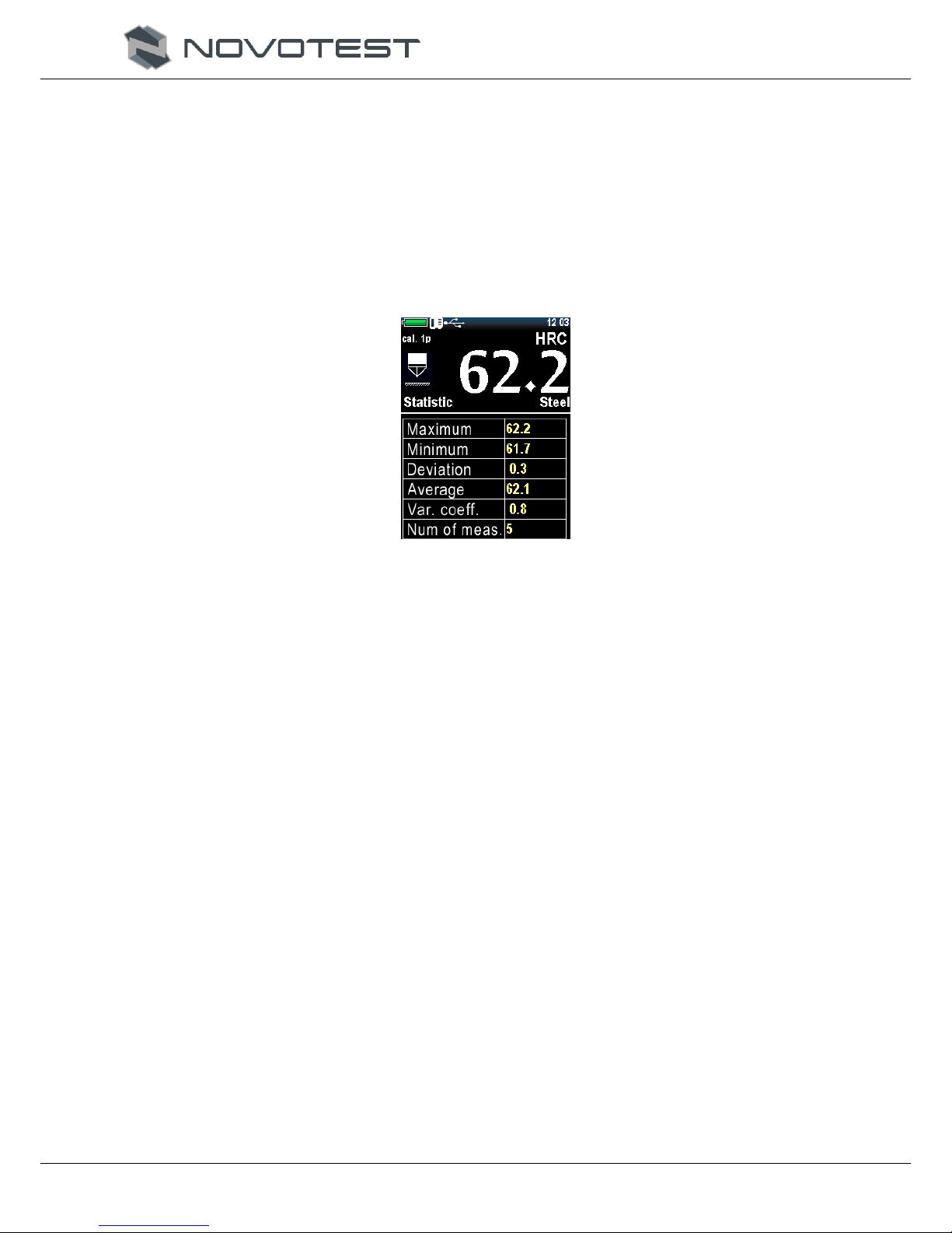
2.3.6.3 Statistics
Statistics mode allows user to view the following parameters in a series of measurements:
maximum;
minimum;
deviation;
average;
coefficient of variation of a random variable;
number of measurements.
Fig. 2.22 shows an example of work in the statistics mode, in which the table lists all the
parameters of a series of measurements.
Figure 2.22 - Statistics mode
2.3.6.4 Intelligent mode
The accuracy of the instrument is influenced by many external factors, which introduce an
additional error in the measurements. It can be:
jiggle of hand;
move of the tested object;
swaying of the probe;
surface cleanliness;
surface roughness.
For ultrasonic probe additionally:
the load is too short or too long;
probe is pressed too lightly or too hard;
low batteries.
Intelligent mode allows to determine the overall sequence of measurements. Select the first three
series of measurements that do not exceed the specified tolerance. After that, the following
measurements, which exceed the specified tolerance, will be excluded from the series, and will not be
taken into account when calculating the average value of the measured hardness from this series
(Figure 2.23).

NOVOTEST.ED.Т-UD3.000 OM
Operation Manual
Hardness Tester NOVOTEST T-UD3
Page. 27
Figure 2.23 - Intelligent mode
A hardness value filled with white means that the device has a fixed common sequence and the
intelligent mode is active (Figure 2.24).
Figure 2.24 - Active Intelligent Mode
To set the tolerance for Intelligent Mode, go to the <Settings> menu, set the tolerance values in
percentages from 1 to 10 (Figure 2.25).
Figure 2.25 - Setting the tolerance for the intelligent mode
Also, in order to reduce the influence of external factors in the device settings, you can include the
Kalman filter or the Median filter.
In order for the instrument readings to be most accurate, the user needs to select the proper filter
for the particular case.
Kalman filter
The Kalman filter is a linear filter, which is used to obtain the truest value. Also, the Kalman filter
can be defined as a filter giving the least mean square error.

NOVOTEST.ED.Т-UD3.000 OM
Operation Manual
Hardness Tester NOVOTEST T-UD3
Page. 28
The main idea of the filter is to find the coefficient C that will correct the received value so that it
would differ from the real value the least.
Kalman filter is recommended to be used when measuring on a product with heterogeneous
structure, where hardness jumps can be observed, which must be taken into account when assessing
the hardness of the product. Kalman filter can reduce the influence of external factors on the
measurements, while not distorting the jumps in hardness.
Median Filter
The median filter - is a nonlinear filter that is applied to signals subjected to pulse interference.
The medial filter is recommended for measuring homogeneous products, in which should be no jumps
in the value of hardness. If, due to external factors, the probe changes the readings, the filter will
smooth it to the normal value.
2.3.6.5 SIGNAL
The mode is active only for the dynamic probe and shows the voltage. M - represents the
maximum value that corresponds to the signal (Figure 2.26).
Figure 2.26 - Signal Mode
2.3.7 Calibration
2.3.7.1. Calibration of scales
To calibrate the probe, 3 samples of material with known hardness value are needed. The hardness
range should be wider than the hardness of the material that will be measured in the future (the value
should be a maximum or more, a minimum or less, and an average).
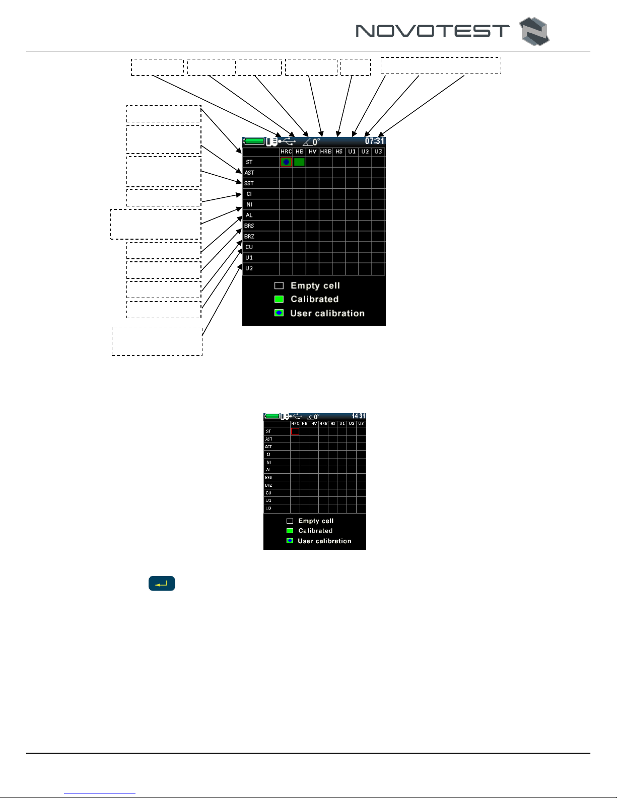
1. Select <CALIBRATION> from the main menu. Each cell in the table corresponds to a specific
calibration scale for a particular material (Figure 2.27). All calibrations can be calibrated for
any materials and any scales, and are thus separated only for the systematization of a set of
calibrations.
NOVOTEST.ED.Т-UD3.000 OM
Operation Manual
Hardness Tester NOVOTEST T-UD3
Page. 29
Figure 2.27 - Calibration Mode
2. Use the navigation keys to select the cell to be calibrated, for example, HRC for steel (Figure
2.28).
Figure 2.28 - Selecting a cell for calibration
1. Push < > to select, you will see the table as in Fig. 2.29. The device, while measurements,
receives nominal codes, the purpose of calibration is to find the correlation between the code
value and the hardness value (to create the function of dependence).
Rokwell C
Brinell
Vickers
Rokvell В
Shore
User Scales
Still
Alloy steel
Stainless steel
Cast iron
High-strength cast
iron
Aluminum
Brass
Bronze
User Material
Copper
NOVOTEST.ED.Т-UD3.000 OM
Operation Manual
Hardness Tester NOVOTEST T-UD3
Page. 30
Figure 2.29 - Calibration table
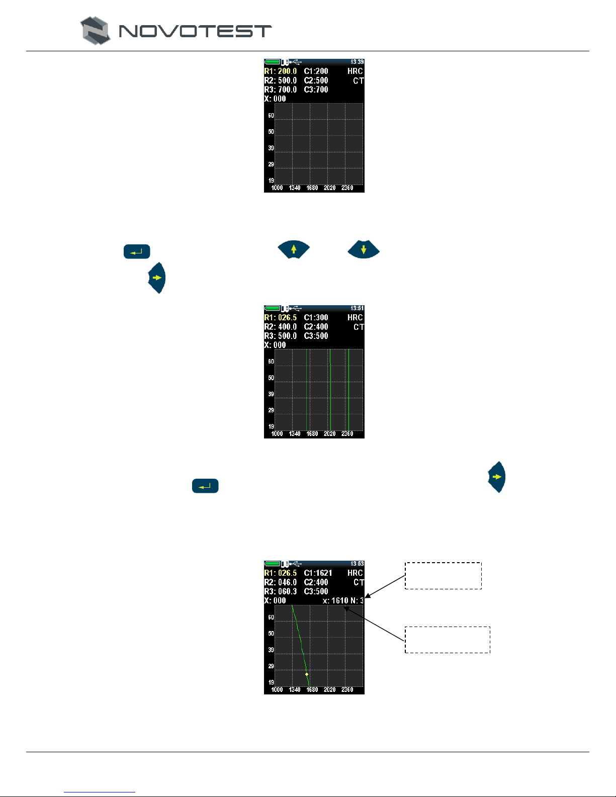
2. To start the calibration, enter the real hardness values of the samples by pressing the key
< >. Using navigation keys < > and < > to set up the real hardness values,
push < > key to enter the next value (Fig. 2.30).
Figure 2.30 - Setting real hardness values
3. Push the key < > one more time to set the first value, than the key < > to edit
harrdness value for the next samples.
4. Then move the cursor to the hardness value according to the sample, and make at least five
measurements (Figure 2.31). Make sure that the value of X (the current code value) does not
change by more than 3%.
Figure 2.31 - Measuring for calibration
Number of
measurements
Current code
value

NOVOTEST.ED.Т-UD3.000 OM
Operation Manual
Hardness Tester NOVOTEST T-UD3
Page. 31
Push < > key if there is an obvious error and the last value will be removed from the
series.
5. Move to the next nominal < >, and complete the same procedure to the other samples
(Fig. 2.32).
Figure 2.32 - Calibration performed for one sample
6. To verify that the value is correct, move the cursor to X: 000 and make several measurements
on one of the samples.
7. Push < > key to exit. Push < > (“YES”), to save, or < > key (“NO”), to exit
without saving (Fig. 2.33).
Figure 2.33 – Saving
2.3.7.2 User (additional) graduation
Each of the stored calibrations can be further adjusted.
The user grading of the hardness tester in the inter-service calibration interval is recommended in
the following cases:
if, while checking the hardness tester with the reference hardness measure, its readings are
stable, but differ from the value of the reference hardness measure;
after long-term storage (more than 3 months.);
after intensive use;
if the operating conditions (temperature, humidity, etc.) change significantly.).
To graduate the hardness tester, one (one-point graduation) or TWO (two-point calibration)
reference hardness measures with the maximum and minimum values are required at the controlled
portion of the hardness scale.
For example, we have two samples of steel with a known hardness value of HRC, and the
instrument shows a stable deviation when measuring the hardness on it.
1. To calibrate by two points, select <CALIBRATION> in the main menu (Fig. 2.34).
Reference value.
Calculating the
average value of a
series of code.

NOVOTEST.ED.Т-UD3.000 OM
Operation Manual
Hardness Tester NOVOTEST T-UD3
Page. 32
Figure 2.34 - Grading
2. Use the navigation keys to select a cell for calibration, for example, HRC for steel.
3. Push < >, and the calibration window will open on the display (Figure 2.35).
Figure 2.35 - The Graduation Window
4. Push < > key to select the number of the calibration points, If there are two samples, you
must select 2 using the keys < > and < >, to confirm push < > (Fig. 2.36).
Figure 2.36 – Two points calibration
5. Moving the cursor with < > key, select the first line. Make about five measurements on
the first reference sample, the device will show the average value of the series according to the
current calibration (Fig. 2.37). If you got obvious error of measurement push < > key,
and the last measurement will be deleted from the seriers.

NOVOTEST.ED.Т-UD3.000 OM
Operation Manual
Hardness Tester NOVOTEST T-UD3
Page. 33
Figure 2.37 - Calibration measurements
Push < >, and using < > and < > set the nominal hardness value of the
reference sample.
6. Use < > key to move to the next value, push < > to save the first one. After the
correction of the hardness value of the first sample the display will look like on Fig 2.38.
Figure 2.38 - After adjusting the first sample
7. Push < >, to set up the second sample value, the procedure will be the same as for the
first one. After the end of all the operations, the display will look as on Fig. 2.39.
Figure 2.39 - After adjustment for the second sample

NOVOTEST.ED.Т-UD3.000 OM
Operation Manual
Hardness Tester NOVOTEST T-UD3
Page. 34
8. Push key < > to save. Push < > (“YES”), to save, or < > key (“NO”), to exit
without saving.
9. The saved user calibration will be marked with a special state of the cell (Fig. 2.40).
Figure 2.40 - User calibration labeling
10. To delete a custom calibration, go to the custom calibration mode and set the value to “0” for
the N parameter (Figure 2.41).
Figure 2.41 - Deleting a user calibration
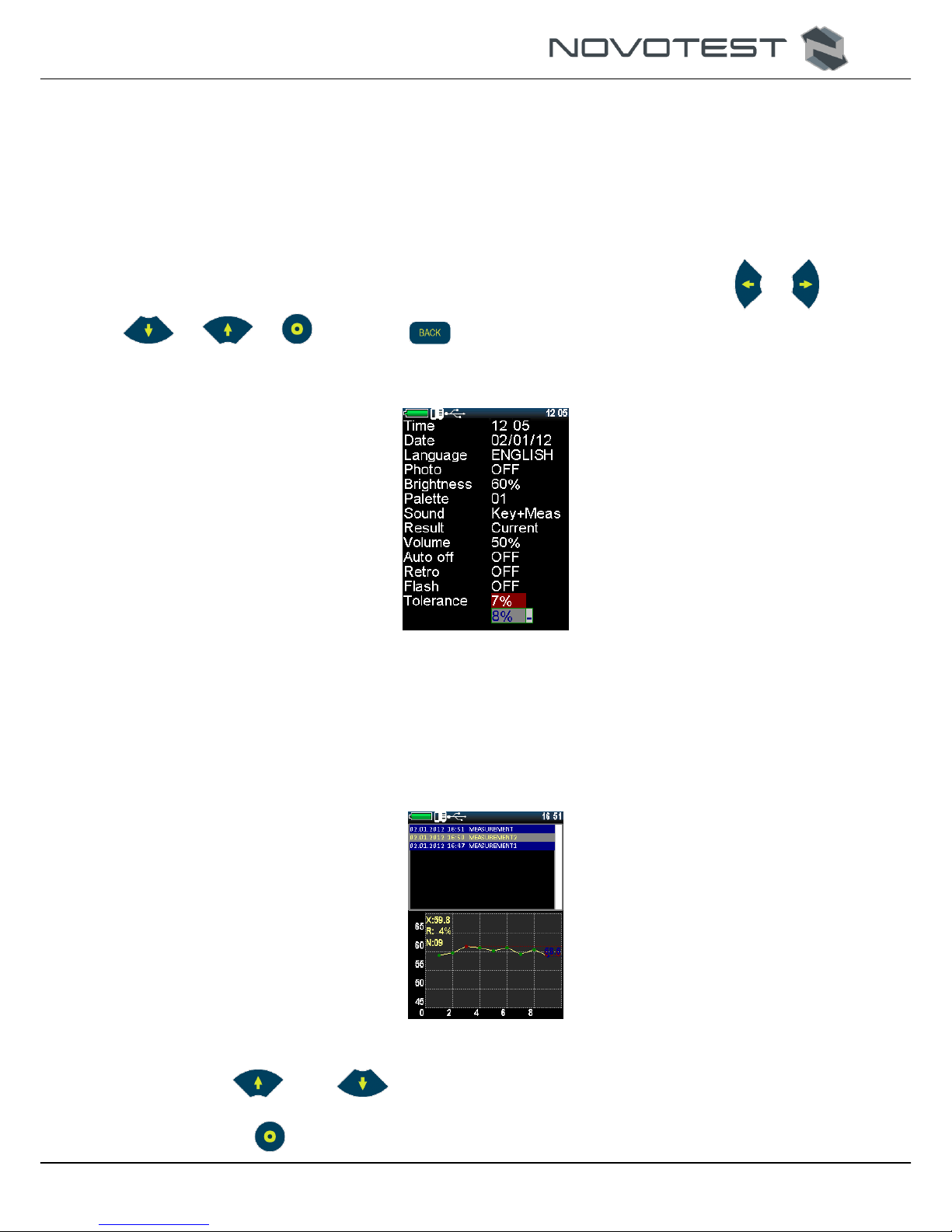
2.3.8 Settings
When the <SETTINGS> menu section is selected, the device enters the setting mode of the
following parameters:
<TIME>: setting the time (24h format);
<DATE>: setting the date format DAY / MONTH / YEAR;
<LANGUAGE>: selection of the menu language of the device (available in English,
Russian, etc.);
<PHOTO>: turn on / off the camera (for versions with the camera);
<BRIGHTNESS>: change the brightness of the display;
<PALETTE>: section of menu themes (creation of a color palette of the menu is made
with special software);
<SOUND>: there are 4 sound modes (off, keyboard, measurement, keyboard and
measurement);
<RESULT>: the display of measurement results can be current (an instantaneous
measurement value is displayed) and calculation of the average value;
<VOLUME>: adjust the volume of the device;
<AUTO-OFF>: setting the device to automatically turn off when not in use;
NOVOTEST.ED.Т-UD3.000 OM
Operation Manual
Hardness Tester NOVOTEST T-UD3
Page. 35
<RETRO>: allows the user to return to the measurement mode with the last measurements
saved after the device is rebooted;
<FLASH>: enable/disable camera flash (for the version with camera);
<TOLERANCE>, %: this parameter is used only for intelligent mode. The values in %
control the range of measurement deviations, which will be included in the calculation on
average for the series in the intelligent mode;
<FILTER>: Kalman or Median, and also turn off the filtering;
<FITLER MODE>: filter mode.
To make changes in the <SETTINGS> section, all the navigation keys are used: < >, < >, <
>, < >, < >. Push key < > to exit.
In Fig. 2.42 <SETTINGS> section is presented.
Figure 2.42 – <SETTINGS> section
2.3.9 Archive
When the <Archive> menu item is selected, the device enters the list of saved measurements,
which displays the name, date and time of the measurement, scale, material and average value (Figure
2.43).
Figure 2.43 - Archive
Use keys < > and < > to navigate.
After selecting the desired saved measurement, the user can view it, and print it: turn on the
printer and press < >.

NOVOTEST.ED.Т-UD3.000 OM
Operation Manual
Hardness Tester NOVOTEST T-UD3
Page. 36
To delete a record from the archive, select the entry with the navigation keys and press < >,
after that the confirmation message <DELETE?> is displayed on the display, press the key < >
To delete or < >, to cancel.
2.3.10 Memory card
When the menu item <MEMORY CARD> is selected, the device goes to the memory menu
(Figure 2.44).
Figure 2.44 - Section <MEMORY CARD>
Creating backup copies of calibrations.
After calibrating the sensor, it is recommended that the user create a backup calibration (usually
the manufacturer calibrates 1-2 scales to check the probe). This is done in order to be able to back
up to the proper calibration after incorrect settings in the future.
After initial saving of the calibrations, the user can always transfer the settings to the probe. This
function is needed to resume proper calibration in case of incorrect probe settings.
Memory card cleaning.
Deleting saved records in the archive and backup copies of the calibrations: after cleaning the SD
card, the archive will be empty and the backup copies of the calibrations are saved.
At the bottom of the screen of this menu is a memory status indicator.
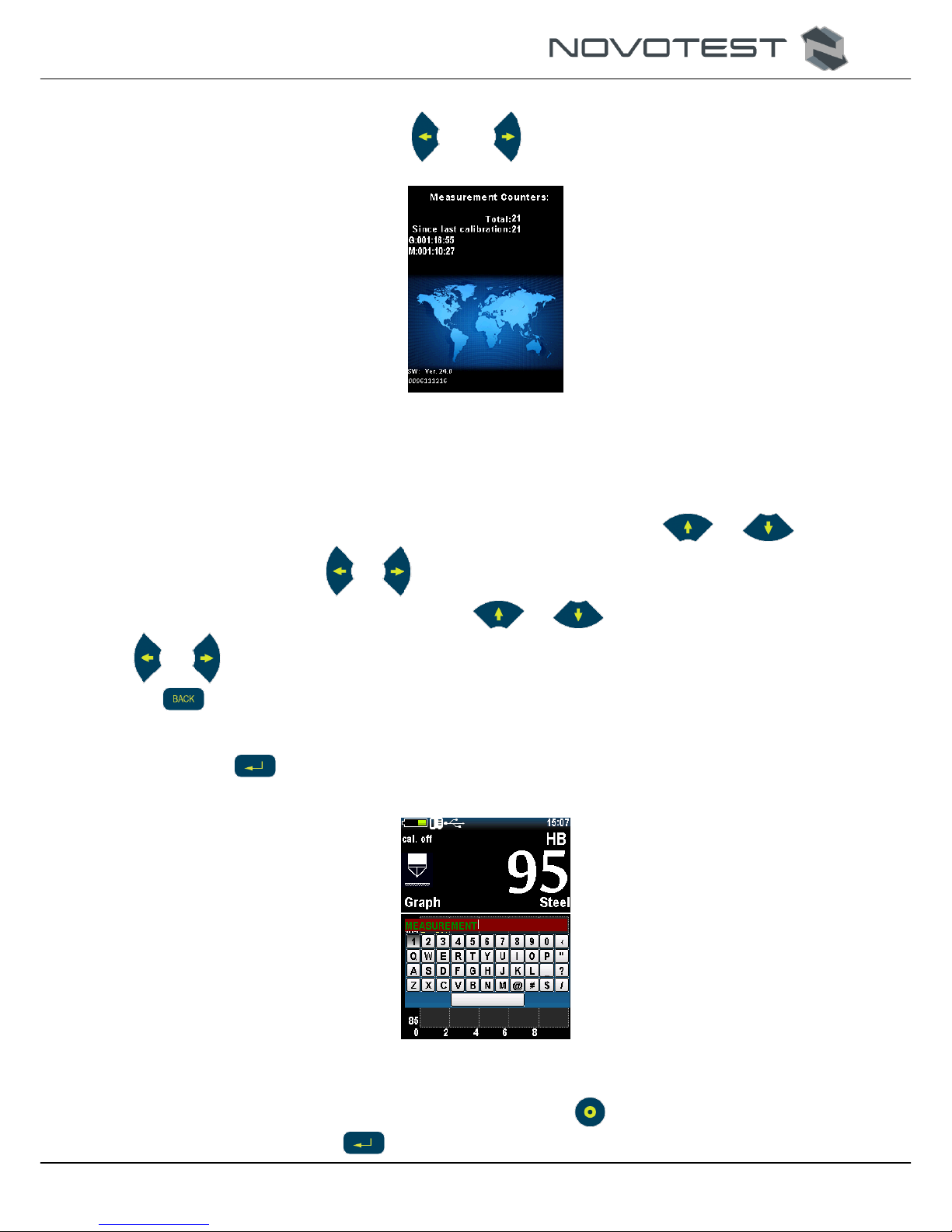
2.3.11 Information
In this menu item, the user can view information about the manufacturer and representative offices
around the world (Figure 2.45).
Figure 2.45 - Section <INFORMATION>
NOVOTEST.ED.Т-UD3.000 OM
Operation Manual
Hardness Tester NOVOTEST T-UD3
Page. 37
Also in this menu item the user can find information about the device and the number of
measurements, use the navigation keys < > and < > to open the needed table (Fig. 2.46).
Figure 2.46 – Information about the device and the measurements number
2.3.12 Photo fixation of the measurements
Photo fixation of the measuring point is used in models with a photo camera.
You can enable photo fixation in the device settings, For this the user needs to go to the
<SETTINGS> section from the main menu, in the settings using the keys < >, < > select
<PHOTO> and using keys < >, < > change <OFF> to <ON>. Also in the settings, the user turns
on the photo flash light, for this, using the keys < >, < > select <FLASH> and using keys
< >, < > Change <OFF> to <ON>. Then you need to exit the <SETTINGS> section with the
key < >. Now the user can start measuring.
After the measurement, to save the measurement (a series of measurements) to archive with photo
fixation of the measurement location, do next:
1. Push < > key (ENTER). A keypad for entering a measurement name (a series of
measurements) appears on the display (Figure 2.47).
Figure 2.47 - Entering a name for the stored measurement
2. Move the cursor to the desired character and press the < > key to select it. When you finish
typing a name, press < > to save. Further, the image from the camera will be transferred

NOVOTEST.ED.Т-UD3.000 OM
Operation Manual
Hardness Tester NOVOTEST T-UD3
Page. 38
to the display in real time and it will be offered <MAKE A PHOTO> or <SAVE WITHOUT
PHOTO> (Fig. 2.48).
Figure 2.48 - Picturing the object
3. Push key < > To save the measurement without photos, or point the camera at the
measured object so that the measuring point can be seen (if the place is poorly visible due to
lack of lighting at the time of shooting, the flash will <highlight> it if it is turned on in the
device settings) push < > to take photo.
4. After shooting, the display will look like in Fig.. 2.49.
Figure 2.49 - After shooting
5. Push < > key to save photoor key < > to take another picture.
6. After saving the photo using the navigation keys < >, < >, < >, < > specify
the measurement location in the picture (Fig. 2.50), Scale and the value of hardness, as well as
the date and time of measurement (creating a snapshot) is indicated automatically. To end the
photo fixation and save the measurement in the archive, press < >.
Note: To save a picture with one measurement point (marker), press < >, And in order to
specify the next point on the same picture, press the key < >. Confirm of storing the
indicated point with the key < > – saves a snapshot without the ability to add a new
measurement point (marker).

NOVOTEST.ED.Т-UD3.000 OM
Operation Manual
Hardness Tester NOVOTEST T-UD3
Page. 39
Figure 2.50 - Marking of the measuring point
2.3.13 Connecting to PC
2.3.13.1 Software setup
When connected the data may be send from and to the device. From the device, arched
measurement data are send. As well as real time display snapshots. To the device color palette
interface schemes could be send (may me changed in settings in the <PALETTE> section, as well as
the archived data may be controlled.
To connect the device to PC do next:
1. Copy driver “DRIVER_FT232RL” for “Windows 7” and “Windows 8” or
“CP210x_VCP_Windows” for “Windows 10” (х64 or х32 up to your OS) and the “AWP
UNIVERSAL” program (.zip type archives) to the PC hard drive or download the updated
versions from the official web site.
2. Unpack the files getting two folders (Fig. 2.51).
Figure 2.51 – Downloaded software
3. Now the user can connect the device to the PC using the USB cable supplied. After
connection, the computer detects a new connected device, but does not find a driver to work
with it, they must be installed manually.
4. For installation, go to <START> CONTROL PANEL> DEVICE MANAGER> in the <COM
and LTP PORTS> section there will be an unidentified device.
5. Open the device properties by double-clicking the left mouse button on it and clicking on the
<DRIVER> tab.
6. Click on the button <UPDATE ...> select <SEARCH DRIVERS ON THIS COMPUTER>.
7. Click on the <SEARCH> button and select the path to the downloaded (copied) folder with the
driver and press the <NEXT> button, after which the driver installation process will begin.
8. Restart the PC after successful driver installation.
9. Install the program to work with the device, for this, run the setup.exe file of the program
installation and click the <INSTALL> button (Figure 2.52).

NOVOTEST.ED.Т-UD3.000 OM
Operation Manual
Hardness Tester NOVOTEST T-UD3
Page. 40
Figure 2.52 – Installing AWP Universal
10. After the installation is completed, the shortcut for the program <AWP UNIVERSAL>
appears on the desktop.
2.3.13.2 Using the software
Connect the device to the PC using USB cable и Run the <AWP UNIVERSAL> program, after
selecting the archive location, the program will start.
In the section (Figure 2.53) <WORK WITH ARCHIVE> the user can view, print, copy and move
data from the archive.
Each record is saved with full measurement information (a series of measurements), in the record
selection window, a brief information:
Name;
Date and time;
Probe (probe);
# of the probe (probe);
# of the device.
To copy data from the instrument to the PC, the user needs to specify the measurement period, and
then press the <COPY> button.
Note: By pressing the <MOVE> button, the data is not simply copied to the PC, but also deleted
from the device memory.

NOVOTEST.ED.Т-UD3.000 OM
Operation Manual
Hardness Tester NOVOTEST T-UD3
Page. 41
Figure 2.53 – Program <AWP UNIVERSAL> section <WORK WITH ARCHIVE>
After selecting a record on the right side of the program, a photo of the tested location appears (if
it is added to the record). Additional information appears in the lower part of the program in the form
of a table and a plotted chart or a histogram of a series of measurements (can be changed using the
dynamic button <GRAPH / HISTOGRAM>). Above the graph is the number of the series, the
hardness scale, and also the material of the measurement object.
The table shows such recording parameters:
Maximum;
Minimum;
Amplitude;
Average value;
Standard error;
Standard deviation;
Variation coefficient;
Uniformity of the series;
Number of measurements.
The saved data can be immediately printed, by pressing the <PRINT> button. The user can also
delete the recording from the instrument using the <DELETE> button.
The data for a certain period (set by the user) or manually selected from the archive can be moved
(deleted from the device memory) or copied (remain in the device memory) to the PC.
Also at the <WORK WITH ARCHIVE> tab the user can make settings to the program.
NOVOTEST.ED.Т-UD3.000 OM
Operation Manual
Hardness Tester NOVOTEST T-UD3
Page. 42
To change the language, press the <ENG / RUS> dynamic key and the program language will
change from Russian to English or vice versa.
To change the location of the archive, click on the location of the archive and select a new archive
location.
To go to our site you need to click on one of the flags or on the planet (international in English),
after clicking the site will open in the default browser.
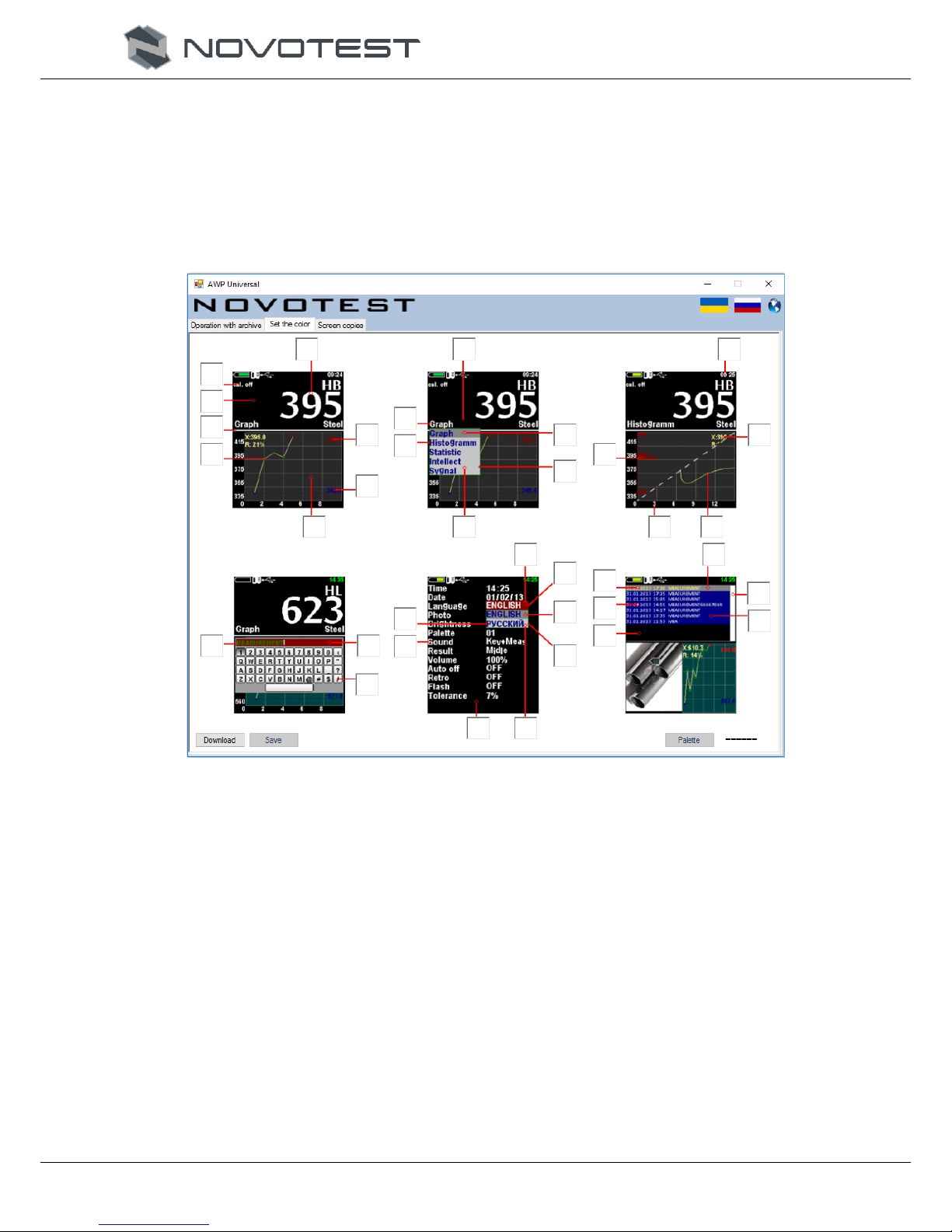
On the <COLOR SETTING> tab, you can create a new one or load and edit the standard color
design of the device (Figure 2.54).
Figure 2.54 – <COLOR SETTING> tab
To load the current color settings, click on the <LOAD> button, and then select the edited color
theme with the <PALETTE> button. To edit, click on the color you want to change, and select a new
one. When all colors are changed, specify the name of the palette and save it on the device with the
<SAVE> key.
On the <SCREEN COPIES> tab, the user can save the screen images on the device in real time
(Figure 2.55).
To save the image, you must press the <CAPTURE> button, after which a message that the screen
shot is saved will be displayed on the PC screen. When all the necessary actions on the device are
<CAPTURED>, the user need to click on the <LOAD> button after which the images will be saved in
the program archive.

NOVOTEST.ED.Т-UD3.000 OM
Operation Manual
Hardness Tester NOVOTEST T-UD3
Page. 43
Figure 2.55 - Screen saving tab

NOVOTEST.ED.Т-UD3.000 OM
Operation Manual
Hardness Tester NOVOTEST T-UD3
Page. 44
3 TECHNICAL MAINTENANCE OF THE PRODUCT AND ITS COMPONENTS
3.1 Security measures
It is recommended that the device commissioned be periodically inspected for monitoring
purposes:
performance;
compliance with the operating conditions;
battery charge level;
absence of external damage to the component parts of the device.
When working with a charger connected to the 220V network at 50 Hz, the requirements stated in
the “Safety rules for the operation of electrical installations of consumers” are mandatory.
If the device is not used for a long time, the batteries should be turned off or removed. In doing so,
the batteries storage rules must be kept.
Those who have been instructed and certified for the II qualification group for safety in working
with electro-radio measuring devices are allowed to work with the device are.
3.2 Verification
The recommended verification interval at least once a year.
The verification procedure (calibration) - further verification, applies to hardness testers
NOVOTEST T-UD3 and establishes methods and means of their primary and periodic verification.
The verification procedure (calibration) - further verification, applies to hardness testers
NOVOTEST T-UD3 and establishes methods and means of their primary and periodic verification
Verification conditions and preparation for it
Verification of the device is carried out under climatic conditions:
temperature from 15 to 280С;
relative humidity 65 ± 15 %;
pressure 101 ± 2 kPa.
The power supply must comply with Table. 1.1. (It is possible to connect an external power
supply if polarity is maintained).
Measures of hardness during verification should be ground to a grinding plate with a mass of not
less than 5 kg, through a layer of lubricant.
3.2.1 Operations and verification means
When carrying out the verification, it is necessary to carry out the operations and to apply the
means of verification specified in Tab. 3.1.
Table 3.1 - Operations and verification means
Name of verification
operations
Number
of items
Name of
verification
means
When is a mandatory
Release from
production and
repair
Operation and
storage
1 2 3 4 5
1. Visual inspection
3.3.2 yes
yes
2. Testing
3.3.3 yes
yes

NOVOTEST.ED.Т-UD3.000 OM
Operation Manual
Hardness Tester NOVOTEST T-UD3
Page. 45
1 2 3 4 5
3. Determination of
the basic error of the
instrument according
to the HRC scale
3.3.4
Reference
hardness test
blocks
yes
yes
4. Determination of
the basic error of the
instrument according
to the НB scale
3.3.5
Reference
hardness test
blocks
yes
yes
5. Determination of
the basic error of the
instrument according
to the НV scale
3.3.6
Reference
hardness test
blocks
yes
yes
3.2.2 Visual inspection
The device should be complicated in accordance with p. 1.3.
No foreign objects detected by hearing when it tilts, should be inside the electronic unit of the
device.
No parts of the probes should have any signs of corrosion and mechanical damage.
3.2.3 Testing
The device is tested according to p 1.7, and also:
for modification of NOVOTEST T-U3, the test is performed with an Ultrasonic Contact
Impedance Probe U1;
for modification NOVOTEST T-D3 testing is carried out with a Rebound Leeb Probe.
3.2.4 Determination of the basic error of the instrument according to the HRC scale
1. Select the HRC hardness measurement.
2. Select the measurement mode statistics.
3. Carry out at least 3 measurements of HRCi on the hardness measures (excluding explicit
measurement errors).
4. 4. Determine the basic error of hardness measurement on the HRC scale using the formula:
, (1)
where n – number of measurements.
5. Select the hardness measurement on the scale of user. НRС.
6. Select the statistics measurement mode p. 2.3.5.
7. Make at least 3 measurements of HRCi on hardness reference blocks (excluding explicit
measurement errors).
8. Determine the basic error of hardness measurement on the HRC scale by the formula (1).
9. If the error exceeds the allowable value (Table 1.2), then it is necessary to calibrate the user
scale according to p. 2.3.7.
10. Repeat operations 6 through 8.
11. The basic error of hardness measurement for the HRC scale and in the scale of use. НRC
should not exceed ± 2,0 НRC.

NOVOTEST.ED.Т-UD3.000 OM
Operation Manual
Hardness Tester NOVOTEST T-UD3
Page. 46
3.2.5 Determination of the basic error of the instrument on the scale HB
1. Select the hardness measurement on the HB scale.
2. Select the statistics measurement mode.
3. Carry out at least 3 measurements of HBi on hardness measures (Excluding explicit
measurement errors).
4. Determine the basic error of hardness measurement on the HB scale by the formula:
, (2)
where n is the number of measurements.
5. Select the hardness measurement on the scale of user. НB.
6. Select the statistics measurement mode.
7. Make at least 3 measurements of НBi on hardness test blocks (excluding explicit measurement
errors).
8. Determine the basic error of hardness measurement on the HB scale by the formula (2).
9. If the error exceeds the allowable value (Table 1.2), then it is necessary to calibrate the user
scale according to p. 2.3.7.
10. Repeat operations 6 through 8.
11. The basic error of hardness measurement for the HB scale and in the scale of use. HB should
not exceed ± 10,0 НRB.
3.2.6 Determination of the basic error of the instrument on the scale НV
1. Select the hardness measurement on the НV scale.
2. Select the statistics measurement mode.
3. Carry out at least 3 measurements of НV on hardness measures (Excluding explicit
measurement errors).
4. Determine the basic error of hardness measurement on the НV scale by the formula:
, (3)
where n is the number of measurements.
5. Select the hardness measurement on the scale of user. НV.
6. Select the statistics measurement mode.
7. Make at least 3 measurements of НV on hardness reference blocks (excluding explicit
measurement errors).
8. Determine the basic error of hardness measurement on the НV scale by the formula (3).
9. If the error exceeds the allowable value (Table 1.2), then it is necessary to calibrate the user
scale according to p. 2.3.7.
10. Repeat operations 6 through 8.
11. The basic error of hardness measurement for the НV scale and in the scale of use. НV should
not exceed ± 15,0 НV.

NOVOTEST.ED.Т-UD3.000 OM
Operation Manual
Hardness Tester NOVOTEST T-UD3
Page. 47
3.2.7 Registration of verification results
Positive results of the primary verification of the device are to be mentioned in the passport.
The results of periodic verification of a device that is recognized as fit for operation are
documented by a protocol of verification of an arbitrary form, a mark in the passport for the device and
its stamping.
A negative result is documented by a certificate of the inadequacy of the device, indicating the
cause, and blanking out the stamps of the previous verification.
3.3 Warranty
The following warranty information is valid for all NOVOTEST products.
The manufacturer guarantees the conformity of the device to the requirements of the technical
conditions under the user's compliance with the conditions of transportation, storage and operation,
and timely maintenance at the manufacturer's premises at least once a year.
3.3.1 Basic Warranty
Your new NOVOTEST device, purchased from the manufacturer or an authorized dealer, is
covered by basic warranty of 1 year. It is also available to extended granted warranty period up to 5
years.
If any part of the device fails due to a defect in the material or production process, it will be
repaired or replaced free of charge by the manufacturer or by any authorized NOVOTEST dealer,
regardless of whether the ownership of the device has passed to another person during the warranty
period.
Warranty for batteries and chargers is provided directly by the manufacturers of batteries, batteries
and chargers and therefore they are not covered by the NOVOTEST warranty. However, your
authorized NOVOTEST dealer will assist you in presenting warranty claims regarding batteries,
batteries and chargers.
The warranty for the device begins to operate from the date of purchase of the device, as a rule, on
the day of shipment of the device to the customer. In the case that the device is purchased by an
intermediary company, the beginning of the warranty period is the time of transfer of the device to the
intermediary.
3.3.2 Extended warranty
A special program for extending the basic warranty period from 1 to 2, 3, 4 or 5 years. To
participate in the program, you must pay a certificate when purchasing equipment. Extended warranty
terms are specified in the certificate.
3.3.3 Warranty for repaired or replaced parts
All NOVOTEST brand spare parts installed during the warranty repair process are covered by the
NOVOTEST guarantee (until the end of the warranty period).
Spare parts replaced during warranty service under warranty are not returned to the owner of the
device.
3.3.4 Wear parts
Parts that are subject to wear during the operation of the device fall into two main categories. The
first includes those parts that require replacement or adjustment at the interval prescribed by the
maintenance schedule of the device, and to the second wear elements, the frequency of replacement or
adjustment of which depends on the operating conditions of the device.
3.3.4.1 Parts replaced with routine maintenance
The parts listed below have a limited service life and need to be replaced or adjusted at intervals
prescribed by the maintenance schedule of the device. The basic warranty extends to these parts until
the moment when their first replacement or adjustment is required. The warranty period for each part

NOVOTEST.ED.Т-UD3.000 OM
Operation Manual
Hardness Tester NOVOTEST T-UD3
Page. 48
can not exceed the restrictions (on the time of operation of the device or operating time) specified in
the conditions of the basic guarantee.
built-in rechargeable batteries;
gaskets, if they are removed in connection with the concomitant adjustment;
oil and working fluids.
3.3.4.2 Wear parts
The parts listed below either have a limited service life, or may require replacement (adjustment)
because of the damage. However, these parts are covered by the basic NOVOTEST warranty for 36 12
months or until the first scheduled maintenance of the device (whichever comes first):
probes and their components;
connecting cables;
details and mechanisms exposed to mechanical influences during operation.
Note: In detail, the wear by friction (such as knives, cutters, movable members probes, ultrasonic
piezoelectric probes, the reference nozzle and so on.) Does not extend the basic guarantee
NOVOTEST, if these parts fail due to normal wear during use of the appliance. However, if during the
warranty period these parts fail due to an initial defect in the material or workmanship, they will be
repaired or replaced according to the basic warranty.
3.3.5 Duties of the owner
The “Operation Manual” and “Passport” contain information on the proper operation and
maintenance of your device.
Proper operation and maintenance of the device will help the user avoid expensive repairs caused
by incorrect operation, neglect or improper maintenance. In addition, following our recommendations
increases the life of the device. Therefore, the owner of the device should:
If a defect or fault is detected, send your device as soon as possible to the manufacturer or
an authorized NOVOTEST dealer for warranty repairs. This will help to minimize the
repair required by your device.
Carry out maintenance for your appliance in accordance with the operating instructions and
the passport.
Note: Neglect of timely maintenance of the device in accordance with the prescribed schedule
deprives you of the rights to warranty repair or replacement of defective parts.
When servicing the appliance, use only original spare parts and NOVOTEST service fluids
(which are marked accordingly).
Make notes on the maintenance performed on the instrument in the passport, save all
invoices and receipts. If necessary, they will serve as proof that the maintenance was
carried out in a timely manner (according to the intervals indicated in the passport), using
the recommended spare parts and operating fluids. This will help you with warranty claims
for defects that may occur as a result of non-compliance with the maintenance schedule of
the instrument or the use of unauthorized parts or materials.
Regularly clean the instrument housing and probes of your device in accordance with the
recommendations of NOVOTEST.
Keep operating and storage conditions in accordance with the recommendations of
NOVOTEST.
3.3.6 Warranty Limitations
NOVOTEST is not responsible if the need for repair or replacement of parts was caused by one of
the following factors:

NOVOTEST.ED.Т-UD3.000 OM
Operation Manual
Hardness Tester NOVOTEST T-UD3
Page. 49
Damage caused by negligent / improper operation of the appliance, a natural disaster,
water ingress into the appliance, the probe, accessories and parts of the appliance (in the
absence of a production fault) by an accident or using the appliance for other purposes;
Operational wear of parts;
Failure to comply with NOVOTEST recommendations for maintenance of the device
within the specified time;
Violation of the operating conditions of the device, recommended by NOVOTEST;
Changes in the design of the device or its components, interference with the operation of
the instrument systems, etc., without agreement with the manufacturer;
Use of batteries and other components of improper quality;
Voltage drop in the mains;
Deny to timely correct any damage identified during routine maintenance;
Factors beyond the scope of NOVOTEST control, for example: air pollution, hurricanes,
chipping, scratches and the use of unsuitable cleaners;
Use of repair technologies not approved by NOVOTEST;
Use of non-original NOVOTEST spare parts and fluids.
Repair operations covered by the NOVOTEST warranty must be performed only by an authorized
NOVOTEST service center.
3.3.7 Other cases not covered by the warranty
The basic NOVOTEST warranty, extended NOVOTEST warranty excludes the liability of
NOVOTEST for any unforeseen or consequential damage incurred as a result of a defect covered by
the above warranties. Such damage is (but is not limited to the following list):
compensation for inconvenience, phone calls, costs of placing and transferring the device,
loss of profits or damage to property;
all warranties become invalid if the device is officially recognized as not subject to repair.
3.3.8 Guarantees and consumer legislation
The basic NOVOTEST warranty, the extended NOVOTEST guarantee do not infringe upon your
legal rights granted to the user by the purchase and sale contract, which is drawn up upon the purchase
of the device from the manufacturer or an authorized NOVOTEST dealer; As well as applicable local
legislation defining the rules for the sale and servicing of consumer goods.
3.4 Maintenance of the device
This maintenance information is valid for all NOVOTEST products.
Maintenance of the device is performed during the entire service life and is divided into:
preventive;
planned.
Preventive maintenance is carried out not less often than once in three months and includes
external inspection, clearing and greasing.
Planned maintenance is carried out by the manufacturer at least once a year and is a mandatory
requirement for maintaining the guarantee from the manufacturer.
It is very important to carry out its maintenance in a timely manner throughout the life of the
device. At the same time, it is necessary to follow the schedule presented in tab. 3.2 (focusing on the
development of the device or the months of its operation, whichever comes first).
The specific list of operations performed during each maintenance depends on the model of the
device, as well as on the year of its production and the amount of operating time. An authorized
NOVOTEST service center will provide the user with information on the work to be performed when
servicing the device.
Records on the routine maintenance of the device are made in the passport for the device.
Information about maintenance is very important, they may be needed to implement your rights to

NOVOTEST.ED.Т-UD3.000 OM
Operation Manual
Hardness Tester NOVOTEST T-UD3
Page. 50
warranty repair of the device. Therefore, always check that at the end of the maintenance period your
authorized NOVOTEST service center has stamped it in the appropriate place under the record of the
procedures performed.
Table 3.2 - Maintenance schedule for NOVOTEST
Device
Maintenance schedule NOVOTEST
All models except those listed below
Annual maintenance is performed after one year
or 2,000 operating hours (whichever occurs first)
Portable hardness testers (Leeb, UCI,
Combined)
Annual maintenance is performed after one year
or 2,000 operating hours (whichever occurs first)
In the event of a malfunction in the operation of the instrument, it must be transferred to the
manufacturer for maintenance. In Table. 3.3. Faults that can be fixed by yourself.

NOVOTEST.ED.Т-UD3.000 OM
Operation Manual
Hardness Tester NOVOTEST T-UD3
Page. 51
Table 3.3 - Possible malfunctions and methods of their elimination
Name of malfunction,
external manifestation and
additional signs
Probable cause
Method of elimination
The device does not turn on
No power
Check the presence and status of
self-contained power
No measurements
Break in the probe circuit
Check and eliminate the break
The instrument displays false
readings
The device is not calibrated or is
influenced by the influencing
factors
Repeat calibration of the device
and eliminate the influence of
external factors

NOVOTEST.ED.Т-UD3.000 OM
Operation Manual
Hardness Tester NOVOTEST T-UD3
Page. 52
4 MAINTENANCE
The device by type of performance and taking into account operating conditions refers to products
that are repaired at special enterprises or at the manufacturer.
To set the device for warranty service in the service center (SC), it is necessary to present
correctly completed passport for the device. SC makes a mark in the passport about setting the device
for warranty service and sends a photocopy to the manufacturer.
Sending the device for warranty (post-warranty) repair or verification should be done with the
passport of the device. In the accompanying documents it is necessary to indicate the mailing details,
telephone and fax of the sender, as well as the way and the address of the return delivery.
Warranty repair is carried out in the presence of a completed passport.
5 STORAGE
Store the device at an ambient temperature of +5 ° C to +40 ° C and relative humidity up to 80%
at a temperature of 25 ° C.
Storage of the batteries of accumulators (BA) should be carried out in a charged state separately
from the device in a dry premise. Duration of storage of the fully charged BA in the detached state:
at a temperature from -20 ° С to +35 ° С - no more than 1 year;
at a temperature from -20 ° С to +45 ° С - no more than 3 months.
Recommended temperature for long-term storage 10 ° C - 30 ° C.
At the end of the shelf life, the batteries should be recycled.
In the case of short-term storage and during interruptions between applications, the device must be
stored in a suitable packaging container. In the storage place there should be no vapors of corrosive
substances (acids, alkalis) and direct sunlight. The device must not be subjected to sudden shocks, falls
or strong vibrations.
Devices should be stacked on shelves or stacked in transport packaging.
For long-term storage, the device must be preserved, for which the electronic unit, probe, power
unit and thickness measures, cleaned of dirt and oil, are placed in separate plastic bags and placed in
separate pockets of the transportation bag of the device.
6 TRANSPORTATION
Packed instruments can be transported by any mode of transport provided the following conditions
are met:
transportation is carried out in factory packaging;
there is no direct exposure to moisture;
the temperature does not exceed -50 ° C to +50 ° C;
humidity does not exceed 95% at temperatures up to 35 ° С;
vibration in the range from 10 to 500 Hz with amplitude up to 0.35 mm and acceleration up to
49 m / s2;
impacts with a peak acceleration value of up to 98 m / s2;
the devices placed in the transport are fixed to avoid falling and collision.
To prevent moisture condensation inside the thickness gauge when transporting it from frost to a
warm room, it is necessary to hold the device for 6 hours at room temperature.
7 RESYCLING
The product does not contain in its design any dangerous or poisonous substances that can harm
human health or the environment and do not pose a threat to life, health of people and the environment
at the end of their service life. In this regard, the recycling of the product can be made according to the
rules for the disposal of general industrial waste. Recycling is carried out separately by groups of
materials: plastic elements, metal fasteners.
The content of precious metals in the components of the product (electronic cards, connectors,
etc.) is extremely small, so it is not appropriate to produce their secondary processing.

NOVOTEST.ED.Т-UD3.000 OM
Operation Manual
Hardness Tester NOVOTEST T-UD3
Page. 53
NOTES
__________________________________________________________________________________
__________________________________________________________________________________
__________________________________________________________________________________
__________________________________________________________________________________
__________________________________________________________________________________
__________________________________________________________________________________
__________________________________________________________________________________
__________________________________________________________________________________
__________________________________________________________________________________
__________________________________________________________________________________
__________________________________________________________________________________
__________________________________________________________________________________
__________________________________________________________________________________
__________________________________________________________________________________
__________________________________________________________________________________
__________________________________________________________________________________
__________________________________________________________________________________
__________________________________________________________________________________
__________________________________________________________________________________
__________________________________________________________________________________
__________________________________________________________________________________
__________________________________________________________________________________
__________________________________________________________________________________
__________________________________________________________________________________
__________________________________________________________________________________
__________________________________________________________________________________
__________________________________________________________________________________
__________________________________________________________________________________
__________________________________________________________________________________
__________________________________________________________________________________
__________________________________________________________________________________
__________________________________________________________________________________
__________________________________________________________________________________
__________________________________________________________________________________
__________________________________________________________________________________
__________________________________________________________________________________
__________________________________________________________________________________
__________________________________________________________________________________
__________________________________________________________________________________
__________________________________________________________________________________
__________________________________________________________________________________
__________________________________________________________________________________
__________________________________________________________________________________
__________________________________________________________________________________
__________________________________________________________________________________
__________________________________________________________________________________
__________________________________________________________________________________
__________________________________________________________________________________
__________________________________________________________________________________
 Loading...