


Aero® Stand
Retrofit Kit Instructions
To Accommodate Aero® 625-925-1225 along with 900-1200-1500
WARNING
IMPROPER OR UNSAFE use of this tool can result in serious bodily injury! is manual contains important information
about product function and safety. Please read and understand this manual BEFORE operating the tool. Please keep this
manual available for other users and owners before they use the tool. is manual should be stored in a safe place.
www.flexco.com

Table of Contents
Aero® Stand Retrot Assembly ....................................................................3
Gear Pawl Ooading System ......................................................................4
Description .....................................................................................................5
Specications..................................................................................................5
Tools Required for Assembly ....................................................................... 5
General Safety Rules ......................................................................................6
Retrot Installations Instructons ................................................................. 8
Operation .....................................................................................................23
www.flexco.com
—2—

Aero® Stand Retrofit Assembly
to Additionally Accommodate 625-925-1225
2
31
3
32
28
8
24
25
23
19
20
22
16
7
17
20
1
Item No. Part Number Description Qty.
1 GQ863 COUNTERWEIGHT AERO® 1225 1
2 GQ860 CHANNEL LB INTERFACE 2
3 GQ865 LIFT BAR G2-G3 1
7 GQ862 PIN WEIGHT ALIGNMENT 2
8 GQ861 ADAPTER ELEV BRACKET 2
16 GQ915 CHAIN WIRE ASSY 625-1225 1
17 GQ909 GUARD CHAIN STAND 625-1225 1
19 G9968 DECAL 925/1500 1
20 G9968 TAPE DBL SD 3M VHB 4936 .75IN (2 PCS 9IN EACH) 1.5 FT
22 GQ858 DECAL 625/1200 1
23 Q2157 CABLE TIE 8 INCH 1
24 GR102 PIN DETENT 9.5mm X 75mm ZN 2
25 G2034 PIN DETENT 8MMX100 ZN 2
28 GQ916 SCRW SHCS M8X20 ZP 4
31 G2036 SCRW SHCS M8X35 ZN 2
32 G2038 NUT NYLOK FLNG M8 ZN 2
—3—

Gear Pawl Offloading System
Assemble Spring Pin into Guard
5
6
27
9
30
33
26
14
15
Assemble
Spring Pin
into Guard
6
5
4
18
10
4
No Spring Pin
13
11
Needed
No Spring Pin
Item No. Part Number Description Qty.
4 GQ868 GUARD PAWL GEAR LIFT SYSTEM 4
5 GQ912 PIN SPRING M5X14 SS 2
6 GQ867 PAWL LIFT SYSTEM 2
9 GQ910 SPACER .406 X .75 X .5 1
10 GQ875 WHEEL LIFT SYSTEM 2
11 GQ876 SHAFT LIFT SYSTEM 1
12 GQ877 NUT SHAFT LIFT SYSTEM 1
13 GQ869 ROLLER LFT SYS SPROCKET STOP 1
14 GQ914 SPROCKET 35B10 THREADED 1
15 GQ870 ROLLER LFT SYS SPROCKET SLEEVE 1
18 GQ866 GEAR PAWL LIFT SYSTEM 2
26 GQ913 RING RETAINING .875 SS 2
27 GQ911 SCREW HHCS M10X160 ZN 1
30 GR145 WSHR OS 8.4IDX240D ZN 2
33 GQ919 SCRW SHCS M8X12 ZP 2
4
Needed
12
18
33
26
30
4
10
www.flexco.com
—4—

Description
is is the Aero® retrot kit for your current stand that is required in order to accommodate the Aero 625,
925, and 1225. e stand will continue to provide convenience and time savings for your belt fabrication.
e design allows for the Aero presses to be loaded quickly and conveniently. e lower beam of the Aero is
xed into the stationary cradle of the press stand. e upper beam is connected into the press using a cable
interface. One person can operate it easily, where movement of the upper half of the press is assisted with
counterweights.
Follow the detailed instructions on page 23 to learn how to o load the pressure in the top beam of the press.
Specifications
Aero Kit Ordering Information
Item Code 09459
Description AERO-STD-CW-G3-625-1225-KIT
Dimensions Assembled
Dimensions Working
Shipping Weight 13.6 kg (30 lbs)
Carton Dimensions
1399 x 1116 x 1930 mm
(55" x 44" x 76")
1583-1883 x 1116 x 1930 mm
(62"-74" x 44" x 76")
813 x 372 x 187 mm
(32" x 14-5/8" x 7-3/8")
Tools Required for Assembly of the Aero
• Ratchet with metric socket set
• Metric open end wrench set
• Metric hex key set
• Adjustable wrench
• Channel lock or pliers
• Dri punch
• Hammer
—5—
®
Stand

General Safety Rules –Save These Instructions–
Signal words:
“DANGER” indicates an imminently hazardous
situation which, if not avoided, will result in
death or serious injury. is signal word is
limited to the most extreme situations.
“WARNING” indicates a potentially hazardous
situation which, if not avoided, could result in
death or serious injury.
“CAUTION” indicates a potentially hazardous
situation which, if not avoided, may result in
minor or moderate injury. It may also be used
to alert against unsafe practices.
Safety Symbol
!
is international safety symbol is used to
identify and call attention to specic
safety matters.
Safety Information
To Avoid Severe Personal Injury or Property
Damage, read carefully and understand the
following Safety Precautions.
1. WORK AREA
!
CAUTION
Keep your work area clean and well lit.
2. PERSONAL SAFETY
!
WARNING
Use safety equipment. Always wear eye
protection, gloves, non-skid safety shoes, and
adhere to other safety standards of the facility
where operating the Aero® Press and Stand.
Stay alert, watch what you are doing and use
common sense when operating a machine.
Do not use machine while tired or under the
inuence of drugs, alcohol, or medication.
A moment of inattention while operating
machines may result in serious personal injury.
Do not wear loose clothing or jewelry. Keep
your hair, clothing, and gloves away from
moving parts. Loose clothes, jewelry, or long
hair can be caught in moving parts.
Abide by all instructions and warning labels.
is equipment is not to be used by children
or persons with reduced physical, sensory or
mental capabilities, or lack of experience and
knowledge of the equipment.
www.flexco.com
—6—
3. TOOL USE AND CARE
!
CAUTION
Check for misalignment or binding of moving
parts, breakage of parts, and any other
condition that may aect the tool’s operation. If
damaged, have the tool serviced before using.
Poorly maintained tools cause many accidents.

General Safety Rules –Save These Instructions–
4. SERVICE AND MAINTENANCE
!
CAUTION
When servicing a tool, use only original
replacement parts. Use of unauthorized parts or
failure to follow Maintenance Instructions, may
create a risk of injury.
Do not wipe plastic parts with solvent. Solvents
such as gasoline, thinner, benzene, carbon
tetrachloride, and alcohol may damage and
crack plastic parts. Do not wipe them with
such solvents. Wipe plastic parts with a so
cloth lightly dampened with soapy water and
drythoroughly.
!
WARNING
Only qualied repair personnel must perform
tool service. Service or maintenance performed
by unqualied personnel could result in a risk
ofinjury.
NEVER use a tool, which is defective or
operating abnormally. If the tool appears to be
operating unusually, making strange noises,
or otherwise appears defective, stop using it
immediately and arrange for repairs.
5. AERO® STAND SAFETY
!
DANGER
Read and understand the Aero® Press operations
manual before using the press in the Aero Stand.
!
CAUTION
Avoid pinch points during the assembly
and in operation. Exercise caution when
moving weights or liing and positioning
ofcomponents.
Exercise care to avoid unbalanced component
conditions during assembly.
Do not cut or kink the liing cables during
handling, assembly, or operation of the
AeroStand.
!
WARNING
Two persons are required for assembly of the
Aero Stand. Portions of the process are dicult
for one person to perform without risk of injury.
Ensure that Aero Press is secure in stand prior
tooperation.
Maintain tools with care. Keep machine parts
clean. Properly serviced tools are less likely
to bind or clutter material and are easier
tocontrol.
Do not move the press stand to a dierent
location while the press is installed.
Do not exceed weight capacity of the Aero
Stand cradle. e Aero Stand retrot kit is
designed to accommodate the 625, 925, and
1225, as well as with the 900, 1200 and 1500.
Ensure that the weight pins are installed
securely in the proper position before operating
the stand.
Ensure that the vertical column door is closed
and latched during operation of the stand.
Avoid raising/lowering of the upper beam with
excessive speed.
—7—

Retrofit Installation Instructions
1. Ensure “AERO® 900”
weight is secure with the
latch (1a and 1b). Further
lock-out of weight is
recommended via clamping
or blocking.
1a
2, Unscrew 2-hole alignment pins (2a and 2b) and replace with 3-hole alignment pins (2c) (part GQ862).
read in fully, then back out to ensure holes face in pin direction (2d).
2a 2b
1b
www.flexco.com
2c 2d
—8—

Retrofit Installation Instructions
3. Move 625/1200 & 925/1500
weight plates to upper position
shown. Insert pins (3a).
Further lock-out of weight is
recommended via clamping or
blocking.
3a
4. Remove guide rod nuts located below bottom weight plate (4a). On upper weight plate hold down black
grommets in place while turning rods and moving rods upward approximately 2" (50 mm) (4b and 4C).
Insert “Aero® 1225” weight (part GQ863) (4d). Hold grommets in place while turning and moving rods
downward into their original position. Reinstall guide rod nuts.
4a 4b
4c 4d
—9—

Retrofit Installation Instructions
5. Remove the two pins from liing bar (not required further). (5a)
Remove the two sets of fasteners at both ends of the liing arm to remove the power cable (save
fasteners). (5b)
Remove the three bolts that connect the three cables to liing arm (save fasteners). (5c)
Remove the liing bar (not required further).
Fasteners reserved for reuse (5d).
5a
5c 5d
6. Open the center weight eyebolt connecting link (6a). Remove cable loop from connecting link (6b).
5b
www.flexco.com
6a 6b
—10—

Retrofit Installation Instructions
7. Remove cable retention
bolt on the rear 3-cable
roller (7a).
7a
8. Remove cable retention bolt on the center
roller (save fasteners) (8a). Remove center
cable (8b and 8c).
8a
8b 8c
—11—

Retrofit Installation Instructions
9. Disengage links of the two remaining cables from the weight compartment (9a). Pull cables and hang
over each respective roller and sha (9b).
9a
9b
10. Remove the sha bolt (10a) and the roller that engaged the three cables positioned directly above the
weight compartment (10b).
www.flexco.com
10a 10b
—12—

Retrofit Installation Instructions
11. Loop the chain-cable assembly (part GQ915)
over the center groove of the center roller from
the kit (11a and 11b). Re-install the original
cable retention bolt and nut (11c). Re-install
the other two cables verifying the cables engage
in the three dierent roller slot positions –
front le, center, and rear right.
e cable on the front roller should be placed on
the right groove
and the cable on
the rear roller
should be placed
on the le groove
(as the installer is
facing the front of
the cradle.)
11a
11b
12. Install the weight o-load roller components (parts GQ869, GQ870, GQ876, GQ914) (12a). Assemble
the parts together (12b). Place these parts inside the top beam and insert the sha bolt through the top
(12c/12d).
11c
12a 12b
12c 12d
—13—

Retrofit Installation Instructions
13. While holding the sha
bolt, manually thread the
sprocket onto the sha
(13a). Ensure the sha
bolt draws through the
opposite top beam hole,
and conrm the sprocket
is fully threaded on the
sha (13b).
13a 13b
14. Position the (GQ877) nut, (GQ866) gear, and (GQ868) inner gear guard oriented as shown (14a).
NOTE: direction of gear as shown is critical. e wider grooved end of the nut needs to be closest to
the inner gear guard (14b). Install on (GQ876) sha threads (14c) and tighten (14d). NOTE: this nut
threads onto the sha with ‘le hand threads’.
14a 14b
www.flexco.com
14c 14d
—14—

Retrofit Installation Instructions
15. On sha hex side, install inner gear guard (GQ868) (15a) and gear (GQ8666) (15b). NOTE: direction of
gear as shown is critical.
15a 15b
16. Route cables and chain over the roller/sprocket assembly (16a). Ensure cables do not cross and chain
is not twisted. Install outer gear guard (with pin) and pawl (GQ867) onto M10 x 160 hex bolt (GQ911)
(16b). Insert hex bolt into top beam hole (16c). Inside top beam, install chain spacer (GQ910) onto hex
bolt. Ensure proper cables are seated in roller grooves, chain is engaged with sprocket, and the chain
spacer is centered between the two rollers (16d).
16b
16a
16c 16d
—15—

Retrofit Installation Instructions
17. Install pawl (GQ867) (17a) then install outer gear guard (17b) (with pin) and original nylok nut on the
cable retention bolt (17c). Tighten nut suciently to provide smooth operation for both pawls (GQ867).
17a 17b
17c
18. Drive spring pins into inner
gear guard (GQ868), both sides.
Ensure operation remains smooth
for both pawls. (18a)
18a
19. Install E-clip retaining rings (GQ913) in the small groove on the sha and nut. Gently tap into groove
(19a). Both sides (19b).
www.flexco.com
19a 19b
—16—

Retrofit Installation Instructions
20. Install wheel (GQ875) using washer (GR145) and socket head screw (GQ919). NOTE: during screw
torque, use wheel as wrenching device to avoid rotation of the le hand threaded sha nut (GQ877).
Both sides (20a and 20b).
20a 20b
21. Inside weight compartment, remove M4 hex
screw and nut from chain clasp (21a). On
center liing eye, ensure connecting link
is oriented as shown, with hex nut on top
portion of link (21b). Separate chain clasp
plates and engage with connecting link.
Install M4 hex screw and nut (21c). NOTE:
ensure chain has no ‘twist’.
21a
21b 21c
—17—

Retrofit Installation Instructions
22. Re-engage cable loops
with li eye connecting
links (22a).
22a
23. Apply weight decals as shown (23a, 23b, 23c and 23d).
23a 23b
www.flexco.com
23c 23d
—18—

Retrofit Installation Instructions
24. Install chain guard (GQ909). Remove adhesive
strips from chain guard. Position inside top
beam as shown, with adhesive strips down.
Engage adhesive strips with top beam inner
anges (24a).
25. Remove original
hold down post
from stand
cradle (25a).
Apply Warning
Label (for use
with Aero® Press
625, 900, 925,
1200, 1225, or
1500).
25a
24a
26. Install two interface brackets (GQ860) on liing bar
(GQ865) in position show for use with Aero 900, 925, and
1500 (26a). Brackets positioned to the inner locations for
use with the Aero 600, 625, 1200, and 1225 (26b). Apply
Caution Label on both sides of the liing bar (26c).
27. Attach liing bar subassembly to cable
eyes using original M8 socket head
screws and anged nylok nuts. Tighten
to the point where the bolt and nut are in
contact with the liing bar. Do not over
tighten. (27a).
26a
26c
26b
27a
—19—

Retrofit Installation Instructions
28. Place adapter brackets (GQ861) on Aero® Stand
cradle. One at the front of the cradle and the
other at approximate position of end of press
(28a). Install M8 x 100 detent pins (G2034)
through holes in adapter bracket tabs on
underside of cradle (28b).
28a
29. Install the umbilical cable. Observe proper
electrical connection ends are positioned for
top and bottom press mating (29a). Capture
in liing bar as shown, at front and back ends
using original M6 socket head screws, anged
Nylok nuts and roller hardware (29b).
28b
29a
www.flexco.com
29b
—20—

Retrofit Installation Instructions
30. Place Aero® Press bottom beam on cradle within the adapter brackets (30a). Place the Aero Press
top beam in place and pin to liing bar using new pins. (GR102) (30b) In weight cabinet, pin the
appropriate counterweight for the press placed in the stand. Elevate Aero top beam to determine the
‘suspended’ position, relocate press base if necessary. To li top press beam the pawl on both sides of the
stand beam are to be located in the up position (30c).
30a
30c
30b
31. Screw the four M8 x 20 socket head screws (GQ916) into the adapter brackets. Locate the ‘T’ nut in
bottom press groove to the appropriate location to engage the adapter bracket as shown. Install screws
(31a and 31b).
31a 31b
—21—

Retrofit Installation Instructions
32. With Aero® Press top beam suspended, check tension of each cable (32a). If a cable has signicantly less
tension than the others, unload weight from top press beam, lock out weight in compartment (32b),
adjust the counterweight liing eye thread engagement to better distribute the cable tension (32c and
32d). NOTE: ensure a minimum of ten threads are engaged with the top counterweight. Orient liing
eyes as shown. Once tensions are balanced, tighten liing eye jam nuts.
32a 32b
32c 32d
www.flexco.com
—22—
Operation
The Aero® 625, 925 and 1225 air bladders are located in the upper press beam.
It is necessary to “off-load” the counterweight system,
to achieve appropriate set-down of the top beam on the belt to be spliced.
During liing and lowering
of the upper press beam, the
pawl levers are placed in the
‘up/disengaged’ position. (a)
a
Once the upper press beam
is positioned on the process
belt, the pawl levers are
lowered to the ‘down/engage’
position. (b)
b
Rotate the wheel in the
direction to li counterweights, which will further lower the upper press beam.
Approximately 2-3 ‘clicks’ of the pawl lever are typically sucient to completely
o-load the counterweight.
Follow operating instructions from Novitool® Aero® Splice Press Safety and
Operation Manual to complete the splice.
—23—

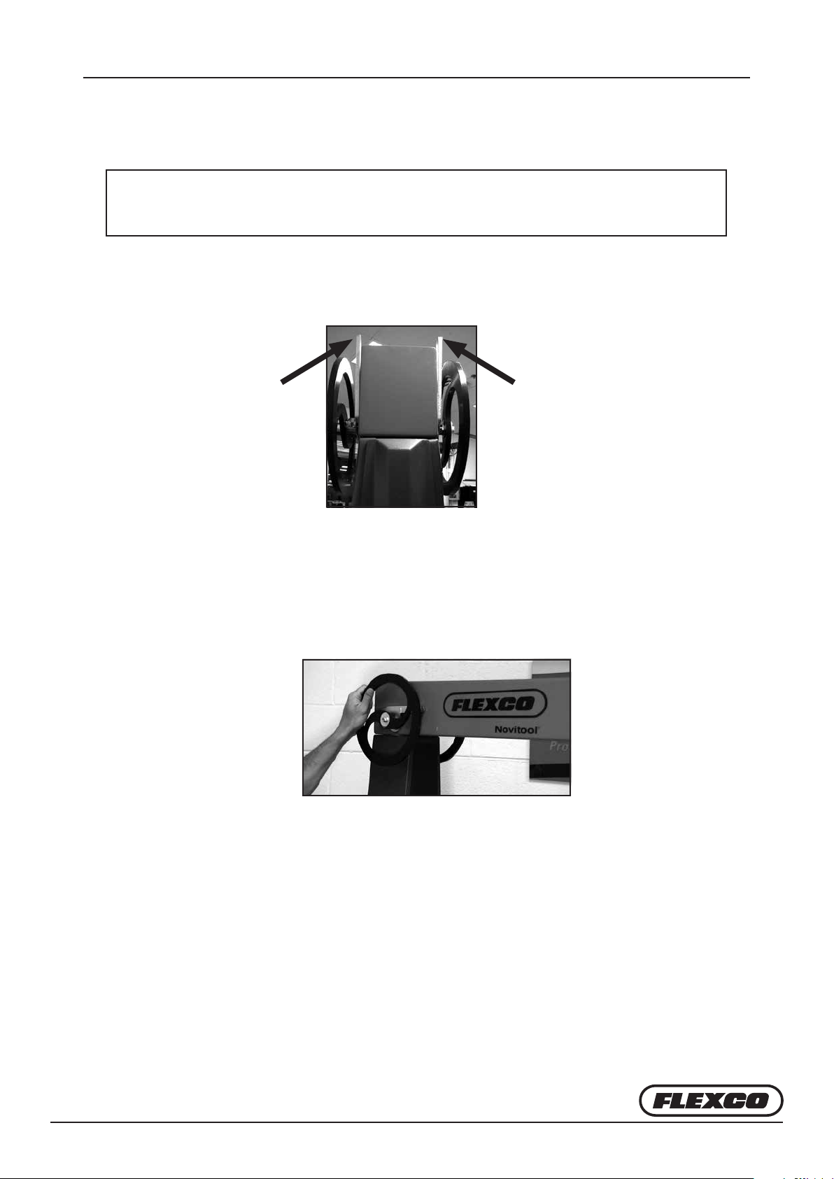
Once the splice process is complete, unfasten the
press connector bolts.
To o-load the top press beam: Grasp the o-load
wheel, (c)
Rotate the o-load wheel in the counterweight
‘li’ direction until the pawl lever is released, (d)
Rotate the pawl lever to the ‘up/disengaged’
position (both pawl levers up), (e)
c
d
Li top press beam with liing arm attached (f)
Do not use the pawl system to service counterweights.
Use counterweight latch system in cabinet, as well as
supplemental lock out methods—blocking/clamping of weights.
e
f
!
WARNING
Flexco Europe GmbH • Leidringer Strasse 40-42 • D-72348 Rosenfeld • Deutschland
Tel: +49-7428-9406-0 • Fax: +49-7428-9406-260 • E-mail: europe@flexco.com
Visit www.flexco.com for other Flexco locations and products.
©2017 Flexible Steel Lacing Company. 06/14/17. For reorder: X4601
 Loading...