


Novell®
www.novell.com
AUTHORIZED DOCUMENTATION
Preboot Services and Imaging Reference
ZENworks® 10 Configuration Management SP3
novdocx (en) 16 April 2010
10.3
April 16, 2010
ZENworks 10 Configuration Management Preboot Services and Imaging Reference

Legal Notices
Novell, Inc., makes no representations or warranties with respect to the contents or use of this documentation, and
specifically disclaims any express or implied warranties of merchantability or fitness for any particular purpose.
Further, Novell, Inc., reserves the right to revise this publication and to make changes to its content, at any time,
without obligation to notify any person or entity of such revisions or changes.
Further, Novell, Inc., makes no representations or warranties with respect to any software, and specifically disclaims
any express or implied warranties of merchantability or fitness for any particular purpose. Further, Novell, Inc.,
reserves the right to make changes to any and all parts of Novell software, at any time, without any obligation to
notify any person or entity of such changes.
Any products or technical information provided under this Agreement may be subject to U.S. export controls and the
trade laws of other countries. You agree to comply with all export control regulations and to obtain any required
licenses or classification to export, re-export or import deliverables. You agree not to export or re-export to entities on
the current U.S. export exclusion lists or to any embargoed or terrorist countries as specified in the U.S. export laws.
You agree to not use deliverables for prohibited nuclear, missile, or chemical biological weaponry end uses. See the
Novell International Trade Services Web page (http://www.novell.com/info/exports/) for more information on
exporting Novell software. Novell assumes no responsibility for your failure to obtain any necessary export
approvals.
novdocx (en) 16 April 2010
Copyright © 2007-2010 Novell, Inc. All rights reserved. No part of this publication may be reproduced, photocopied,
stored on a retrieval system, or transmitted without the express written consent of the publisher.
Novell, Inc.
404 Wyman Street, Suite 500
Waltham, MA 02451
U.S.A.
www.novell.com
Online Documentation: To access the latest online documentation for this and other Novell products, see
the Novell Documentation Web page (http://www.novell.com/documentation).

Novell Trademarks
For Novell trademarks, see the Novell Trademark and Service Mark list (http://www.novell.com/company/legal/
trademarks/tmlist.html).
Third-Party Materials
All third-party trademarks are the property of their respective owners.
novdocx (en) 16 April 2010

novdocx (en) 16 April 2010
4 ZENworks 10 Configuration Management Preboot Services and Imaging Reference

Contents
About This Guide 11
1Overview 13
1.1 Brief Overview . . . . . . . . . . . . . . . . . . . . . . . . . . . . . . . . . . . . . . . . . . . . . . . . . . . . . . . . . . . . . 13
1.1.1 Preboot Services Functionality . . . . . . . . . . . . . . . . . . . . . . . . . . . . . . . . . . . . . . . . . 13
1.1.2 Preboot Services Strategies . . . . . . . . . . . . . . . . . . . . . . . . . . . . . . . . . . . . . . . . . . . 14
1.1.3 Imaging Bundles . . . . . . . . . . . . . . . . . . . . . . . . . . . . . . . . . . . . . . . . . . . . . . . . . . . . 14
1.1.4 Configuring Preboot Services . . . . . . . . . . . . . . . . . . . . . . . . . . . . . . . . . . . . . . . . . . 15
1.1.5 Setting Up Devices to Use Imaging Bundles . . . . . . . . . . . . . . . . . . . . . . . . . . . . . . . 16
1.2 What Is the Preboot Execution Environment (PXE)?. . . . . . . . . . . . . . . . . . . . . . . . . . . . . . . . 17
1.2.1 Understanding How Preboot Services Uses PXE . . . . . . . . . . . . . . . . . . . . . . . . . . . 17
1.2.2 Understanding the ZENworks NBPs . . . . . . . . . . . . . . . . . . . . . . . . . . . . . . . . . . . . . 17
1.2.3 Preparing to Use PXE . . . . . . . . . . . . . . . . . . . . . . . . . . . . . . . . . . . . . . . . . . . . . . . . 19
1.3 Preboot Services Functionality. . . . . . . . . . . . . . . . . . . . . . . . . . . . . . . . . . . . . . . . . . . . . . . . . 19
1.3.1 Imaging Bundles . . . . . . . . . . . . . . . . . . . . . . . . . . . . . . . . . . . . . . . . . . . . . . . . . . . . 19
1.3.2 Novell Preboot Services Menu . . . . . . . . . . . . . . . . . . . . . . . . . . . . . . . . . . . . . . . . . 22
1.3.3 Non-Registered Device Settings . . . . . . . . . . . . . . . . . . . . . . . . . . . . . . . . . . . . . . . . 22
1.3.4 Device Imaging Work Assignment. . . . . . . . . . . . . . . . . . . . . . . . . . . . . . . . . . . . . . . 23
1.3.5 Server Referral List . . . . . . . . . . . . . . . . . . . . . . . . . . . . . . . . . . . . . . . . . . . . . . . . . . 25
1.3.6 Intel Active Management Technology (AMT). . . . . . . . . . . . . . . . . . . . . . . . . . . . . . . 26
1.4 The Preboot Services Processes. . . . . . . . . . . . . . . . . . . . . . . . . . . . . . . . . . . . . . . . . . . . . . . 26
1.4.1 A Typical Preboot Services Operation. . . . . . . . . . . . . . . . . . . . . . . . . . . . . . . . . . . . 26
1.4.2 Illustrating the Preboot Services Processes . . . . . . . . . . . . . . . . . . . . . . . . . . . . . . . 27
1.5 Preboot Strategies . . . . . . . . . . . . . . . . . . . . . . . . . . . . . . . . . . . . . . . . . . . . . . . . . . . . . . . . . . 34
1.5.1 Automating Imaging Tasks . . . . . . . . . . . . . . . . . . . . . . . . . . . . . . . . . . . . . . . . . . . . 34
1.5.2 Creating, Installing, and Restoring Standard Images . . . . . . . . . . . . . . . . . . . . . . . . 35
1.5.3 Reimaging Corrupted Devices. . . . . . . . . . . . . . . . . . . . . . . . . . . . . . . . . . . . . . . . . . 36
1.5.4 Restoring Lab Devices to a Clean State . . . . . . . . . . . . . . . . . . . . . . . . . . . . . . . . . . 36
1.5.5 Setting Up Devices for Future Reimaging . . . . . . . . . . . . . . . . . . . . . . . . . . . . . . . . . 37
1.5.6 Multicasting Device Images . . . . . . . . . . . . . . . . . . . . . . . . . . . . . . . . . . . . . . . . . . . . 37
novdocx (en) 16 April 2010
2 Setting Up Preboot Services and Imaging 41
2.1 Preparing a Preboot Services Imaging Server . . . . . . . . . . . . . . . . . . . . . . . . . . . . . . . . . . . . . 41
2.2 Preparing a Satellite with the Imaging Role . . . . . . . . . . . . . . . . . . . . . . . . . . . . . . . . . . . . . . . 42
2.2.1 Understanding the Imaging Role . . . . . . . . . . . . . . . . . . . . . . . . . . . . . . . . . . . . . . . . 42
2.2.2 Configuring the Imaging Role to the Satellite . . . . . . . . . . . . . . . . . . . . . . . . . . . . . . 42
2.2.3 Illustrating the Preboot Services Processes on the Imaging Satellite . . . . . . . . . . . . 43
2.3 Setting Up the Preboot Services Methods for ZENworks Imaging. . . . . . . . . . . . . . . . . . . . . . 46
2.3.1 Using Preboot Services (PXE). . . . . . . . . . . . . . . . . . . . . . . . . . . . . . . . . . . . . . . . . . 47
2.3.2 Preparing Imaging Boot CDs or DVDs . . . . . . . . . . . . . . . . . . . . . . . . . . . . . . . . . . . 47
2.3.3 Configuring with ZENworks Imaging Media Creator . . . . . . . . . . . . . . . . . . . . . . . . . 49
2.3.4 Managing ZENworks Partitions . . . . . . . . . . . . . . . . . . . . . . . . . . . . . . . . . . . . . . . . . 56
2.4 Deploying and Managing Preboot Services . . . . . . . . . . . . . . . . . . . . . . . . . . . . . . . . . . . . . . . 59
2.4.1 Checking the Preboot Services Imaging Server Setup . . . . . . . . . . . . . . . . . . . . . . . 59
2.4.2 Deploying Preboot Services in a Network Environment . . . . . . . . . . . . . . . . . . . . . . 60
2.4.3 Administering Preboot Services. . . . . . . . . . . . . . . . . . . . . . . . . . . . . . . . . . . . . . . . . 68
2.4.4 Editing the Novell Preboot Services Menu . . . . . . . . . . . . . . . . . . . . . . . . . . . . . . . . 71
2.5 Configuring Preboot Services Defaults for ZENworks Imaging . . . . . . . . . . . . . . . . . . . . . . . . 73
2.5.1 Configuring Novell Preboot Services Menu Options . . . . . . . . . . . . . . . . . . . . . . . . . 74
Contents 5

2.5.2 Configuring Non-Registered Device Settings . . . . . . . . . . . . . . . . . . . . . . . . . . . . . . 75
2.5.3 Configuring Device Imaging Work Assignments . . . . . . . . . . . . . . . . . . . . . . . . . . . . 79
2.5.4 Configuring the Server Referral List . . . . . . . . . . . . . . . . . . . . . . . . . . . . . . . . . . . . . 90
2.5.5 Configuring Intel Active Management Technology (AMT) . . . . . . . . . . . . . . . . . . . . . 94
2.6 Overriding Preboot Services Defaults . . . . . . . . . . . . . . . . . . . . . . . . . . . . . . . . . . . . . . . . . . . 94
2.7 Enabling PXE on Devices . . . . . . . . . . . . . . . . . . . . . . . . . . . . . . . . . . . . . . . . . . . . . . . . . . . . 96
2.7.1 Enabling PXE on a PXE-Capable Device . . . . . . . . . . . . . . . . . . . . . . . . . . . . . . . . . 96
2.7.2 Verifying That PXE Is Enabled on a Device . . . . . . . . . . . . . . . . . . . . . . . . . . . . . . . 97
2.8 Setting Up Devices for ZENworks Imaging . . . . . . . . . . . . . . . . . . . . . . . . . . . . . . . . . . . . . . . 97
2.8.1 Device Requirements . . . . . . . . . . . . . . . . . . . . . . . . . . . . . . . . . . . . . . . . . . . . . . . . 97
2.8.2 Enabling a Device for Imaging Operations . . . . . . . . . . . . . . . . . . . . . . . . . . . . . . . . 98
3 Using Imaging 99
3.1 Imaging Devices. . . . . . . . . . . . . . . . . . . . . . . . . . . . . . . . . . . . . . . . . . . . . . . . . . . . . . . . . . . . 99
3.1.1 Using ZENworks Control Center for Imaging. . . . . . . . . . . . . . . . . . . . . . . . . . . . . . . 99
3.1.2 Using the Command Line for ZENworks Imaging . . . . . . . . . . . . . . . . . . . . . . . . . . 107
3.1.3 Setting Up Disconnected Imaging Operations . . . . . . . . . . . . . . . . . . . . . . . . . . . . . 117
3.2 Multicasting Images for ZENworks Imaging. . . . . . . . . . . . . . . . . . . . . . . . . . . . . . . . . . . . . . 122
3.2.1 Using ZENworks Control Center to Multicast an Image. . . . . . . . . . . . . . . . . . . . . . 122
3.2.2 Using the Command Line to Multicast an Image . . . . . . . . . . . . . . . . . . . . . . . . . . . 127
3.3 Configuring Imaging Script Bundles for ZENworks Imaging . . . . . . . . . . . . . . . . . . . . . . . . . 132
3.4 Assigning Imaging Bundles . . . . . . . . . . . . . . . . . . . . . . . . . . . . . . . . . . . . . . . . . . . . . . . . . . 134
3.4.1 Using the Devices Tab to Assign Bundles. . . . . . . . . . . . . . . . . . . . . . . . . . . . . . . . 134
3.4.2 Assigning Devices to Bundle Groups . . . . . . . . . . . . . . . . . . . . . . . . . . . . . . . . . . . 135
3.4.3 Using the Bundles Tab to Assign Bundles. . . . . . . . . . . . . . . . . . . . . . . . . . . . . . . . 136
3.4.4 Assigning Bundles to Non-Registered Devices . . . . . . . . . . . . . . . . . . . . . . . . . . . . 137
3.5 Editing Imaging Work . . . . . . . . . . . . . . . . . . . . . . . . . . . . . . . . . . . . . . . . . . . . . . . . . . . . . . . 138
novdocx (en) 16 April 2010
4 Imaging Operations in a ZENworks Asset Management Agent and ZENworks
Desktop Management Agent Coexistence Environment 143
4.1 Taking an Image of a Device that has the ZDM 7.x Agent and the ZENworks Adaptive Agent with
Asset Management Installed . . . . . . . . . . . . . . . . . . . . . . . . . . . . . . . . . . . . . . . . . . . . . . . . . 143
4.2 Restoring the Image. . . . . . . . . . . . . . . . . . . . . . . . . . . . . . . . . . . . . . . . . . . . . . . . . . . . . . . . 144
4.2.1 Restoring the Image on the Same Device Whose Image was Taken . . . . . . . . . . . 144
4.2.2 Restoring the Image to Another Device that Has Only the ZDM 7.x Agent Installed 144
4.2.3 Restoring the Image to a Non-Registered Device . . . . . . . . . . . . . . . . . . . . . . . . . . 145
A Preboot Actions 147
A.1 Action - Imaging Script . . . . . . . . . . . . . . . . . . . . . . . . . . . . . . . . . . . . . . . . . . . . . . . . . . . . . 147
A.1.1 Adding a New Imaging Script . . . . . . . . . . . . . . . . . . . . . . . . . . . . . . . . . . . . . . . . . 148
A.1.2 Editing an Existing Imaging Script . . . . . . . . . . . . . . . . . . . . . . . . . . . . . . . . . . . . . . 148
A.2 Action - Linked Application Bundle. . . . . . . . . . . . . . . . . . . . . . . . . . . . . . . . . . . . . . . . . . . . . 148
A.3 Action - Multicast Image Set . . . . . . . . . . . . . . . . . . . . . . . . . . . . . . . . . . . . . . . . . . . . . . . . . 149
A.3.1 Adding a Multicast Image Set . . . . . . . . . . . . . . . . . . . . . . . . . . . . . . . . . . . . . . . . . 150
A.3.2 Editing a Multicast Image Set . . . . . . . . . . . . . . . . . . . . . . . . . . . . . . . . . . . . . . . . . 150
A.4 Action - ZENworks Image . . . . . . . . . . . . . . . . . . . . . . . . . . . . . . . . . . . . . . . . . . . . . . . . . . . 151
A.4.1 Adding a ZENworks Image . . . . . . . . . . . . . . . . . . . . . . . . . . . . . . . . . . . . . . . . . . . 151
A.4.2 Editing a ZENworks Image . . . . . . . . . . . . . . . . . . . . . . . . . . . . . . . . . . . . . . . . . . . 151
A.5 Action - Third Party Image . . . . . . . . . . . . . . . . . . . . . . . . . . . . . . . . . . . . . . . . . . . . . . . . . . . 152
A.5.1 Adding a Third-Party Image . . . . . . . . . . . . . . . . . . . . . . . . . . . . . . . . . . . . . . . . . . . 152
A.5.2 Editing a Third-Party Image . . . . . . . . . . . . . . . . . . . . . . . . . . . . . . . . . . . . . . . . . . . 152
6 ZENworks 10 Configuration Management Preboot Services and Imaging Reference

B File Sets and Image Numbers 155
B.1 File Sets . . . . . . . . . . . . . . . . . . . . . . . . . . . . . . . . . . . . . . . . . . . . . . . . . . . . . . . . . . . . . . . . . 155
B.2 Image Numbers . . . . . . . . . . . . . . . . . . . . . . . . . . . . . . . . . . . . . . . . . . . . . . . . . . . . . . . . . . . 155
C Replicating the TFTP Directory 157
C.1 Configuring the TFTP Directory Replication Settings at the Management Zone Level . . . . . 157
C.2 Configuring the TFTP Directory Replication Settings at the Folder Level . . . . . . . . . . . . . . . 160
C.3 Configuring the TFTP Directory Replication Settings at the Device Level . . . . . . . . . . . . . . . 161
C.4 Understanding the TFTP Replication Schedule Types . . . . . . . . . . . . . . . . . . . . . . . . . . . . . 163
C.4.1 Date Specific . . . . . . . . . . . . . . . . . . . . . . . . . . . . . . . . . . . . . . . . . . . . . . . . . . . . . . 163
C.4.2 Recurring . . . . . . . . . . . . . . . . . . . . . . . . . . . . . . . . . . . . . . . . . . . . . . . . . . . . . . . . . 163
C.5 Resolving Circular Dependency on the Master Primary Server. . . . . . . . . . . . . . . . . . . . . . . 164
C.5.1 Resolving Circular Dependency at the Management Zone Level . . . . . . . . . . . . . . 165
C.5.2 Resolving Circular Dependency at the Folder Level . . . . . . . . . . . . . . . . . . . . . . . . 165
C.5.3 Resolving Circular Dependency at the Device Level . . . . . . . . . . . . . . . . . . . . . . . . 165
D Third-Party Imaging 167
D.1 Things to Know Before Working on ZENworks Third-Party Imaging . . . . . . . . . . . . . . . . . . . 167
D.2 Performing ZENworks Third-Party Imaging by Using ZENworks Control Center. . . . . . . . . . 168
D.3 Setting Up Preboot Services for ZENworks Third-Party Imaging. . . . . . . . . . . . . . . . . . . . . . 168
D.4 Performing ZENworks Third-Party Imaging in the Maintenance Mode . . . . . . . . . . . . . . . . . 169
D.4.1 Launching the . . . . . . . . . . . . . . . . . . Novell ZENworks Third Party Imaging Utility170
D.4.2 Taking an Image of a Device and Storing it Locally. . . . . . . . . . . . . . . . . . . . . . . . . 170
D.4.3 Taking an Image of a Device and Storing it in a Remote Repository . . . . . . . . . . . 171
D.4.4 Restoring a Locally Stored Image . . . . . . . . . . . . . . . . . . . . . . . . . . . . . . . . . . . . . . 173
D.4.5 Restoring an Image to a Device on a Shared Network Location . . . . . . . . . . . . . . . 174
D.4.6 Adding, Deleting, or Activating Disk Partitions. . . . . . . . . . . . . . . . . . . . . . . . . . . . . 175
D.4.7 Querying for the Third-Party Imaging Work . . . . . . . . . . . . . . . . . . . . . . . . . . . . . . . 177
D.5 Configuring the Destination Disk Structure Before Restoring a WIM Image . . . . . . . . . . . . . 177
novdocx (en) 16 April 2010
E Imaging Utilities and Components 181
E.1 Image Explorer (zmgexp). . . . . . . . . . . . . . . . . . . . . . . . . . . . . . . . . . . . . . . . . . . . . . . . . . . . 181
E.1.1 Starting Image Explorer on ZENworks Server . . . . . . . . . . . . . . . . . . . . . . . . . . . . . 181
E.1.2 Installing and Starting the Image Explorer on a Standalone Device . . . . . . . . . . . . 182
E.1.3 Determining the Image Explorer Version . . . . . . . . . . . . . . . . . . . . . . . . . . . . . . . . . 183
E.1.4 Image Explorer versus Windows Explorer. . . . . . . . . . . . . . . . . . . . . . . . . . . . . . . . 183
E.1.5 Opening an Image . . . . . . . . . . . . . . . . . . . . . . . . . . . . . . . . . . . . . . . . . . . . . . . . . . 183
E.1.6 Saving Image Changes and Exiting the Utility. . . . . . . . . . . . . . . . . . . . . . . . . . . . . 184
E.1.7 Managing Image Properties. . . . . . . . . . . . . . . . . . . . . . . . . . . . . . . . . . . . . . . . . . . 184
E.1.8 Image File Operations . . . . . . . . . . . . . . . . . . . . . . . . . . . . . . . . . . . . . . . . . . . . . . . 186
E.1.9 Modifying Image Content . . . . . . . . . . . . . . . . . . . . . . . . . . . . . . . . . . . . . . . . . . . . . 191
E.1.10 Creating a New Image File . . . . . . . . . . . . . . . . . . . . . . . . . . . . . . . . . . . . . . . . . . . 193
E.2 Novell ZENworks Configuration Management Imaging Agent (novell-ziswin) . . . . . . . . . . . . 194
E.3 Novell ZENworks ISD Service (novell-zisdservice) . . . . . . . . . . . . . . . . . . . . . . . . . . . . . . . . 195
E.3.1 Understanding the SID . . . . . . . . . . . . . . . . . . . . . . . . . . . . . . . . . . . . . . . . . . . . . . 196
E.3.2 Understanding the ZENworks SIDchanger . . . . . . . . . . . . . . . . . . . . . . . . . . . . . . . 197
E.3.3 Disabling the SIDchanger . . . . . . . . . . . . . . . . . . . . . . . . . . . . . . . . . . . . . . . . . . . . 198
E.4 Image-Safe Data Viewer and Editor (zisview and zisedit) . . . . . . . . . . . . . . . . . . . . . . . . . . . 198
E.4.1 Information Displayed by the Image-Safe Data Viewer . . . . . . . . . . . . . . . . . . . . . . 199
E.4.2 Using the Image-Safe Data Viewer . . . . . . . . . . . . . . . . . . . . . . . . . . . . . . . . . . . . . 200
E.4.3 Using the Image-Safe Data Editor . . . . . . . . . . . . . . . . . . . . . . . . . . . . . . . . . . . . . . 201
E.5 ZENworks Imaging Floppy Boot Disk Creator (zmediacreator) . . . . . . . . . . . . . . . . . . . . . . . 202
Contents 7

E.6 Imaging Configuration Parameters (settings.txt) . . . . . . . . . . . . . . . . . . . . . . . . . . . . . . . . . . 203
E.7 Imaging Boot Parameter for PCMCIA Cards . . . . . . . . . . . . . . . . . . . . . . . . . . . . . . . . . . . . . 206
E.8 Imaging Server. . . . . . . . . . . . . . . . . . . . . . . . . . . . . . . . . . . . . . . . . . . . . . . . . . . . . . . . . . . . 206
E.8.1 Initiating the Imaging Processes . . . . . . . . . . . . . . . . . . . . . . . . . . . . . . . . . . . . . . . 206
E.8.2 Viewing Information About Imaging Requests . . . . . . . . . . . . . . . . . . . . . . . . . . . . . 215
E.8.3 Starting a Manual Multicast Session . . . . . . . . . . . . . . . . . . . . . . . . . . . . . . . . . . . . 216
E.9 TFTP Client for WinPE. . . . . . . . . . . . . . . . . . . . . . . . . . . . . . . . . . . . . . . . . . . . . . . . . . . . . . 216
F ZENworks Imaging Engine Commands 217
F.1 Help Mode . . . . . . . . . . . . . . . . . . . . . . . . . . . . . . . . . . . . . . . . . . . . . . . . . . . . . . . . . . . . . . . 217
F.1.1 Using the ZENworks Imaging Engine Menu for Help . . . . . . . . . . . . . . . . . . . . . . . 218
F.1.2 Using the Imaging Maintenance Mode Prompt for Help . . . . . . . . . . . . . . . . . . . . . 218
F.2 Automatic (Query for Work) Mode . . . . . . . . . . . . . . . . . . . . . . . . . . . . . . . . . . . . . . . . . . . . . 218
F.2.1 Using the ZENworks Imaging Engine Menu to Query for Work. . . . . . . . . . . . . . . . 219
F.2.2 Using the Imaging Maintenance Mode Prompt to Query for Work . . . . . . . . . . . . . 219
F.3 Make Mode . . . . . . . . . . . . . . . . . . . . . . . . . . . . . . . . . . . . . . . . . . . . . . . . . . . . . . . . . . . . . . 219
F.3.1 Make Locally . . . . . . . . . . . . . . . . . . . . . . . . . . . . . . . . . . . . . . . . . . . . . . . . . . . . . . 220
F.3.2 Make to Proxy . . . . . . . . . . . . . . . . . . . . . . . . . . . . . . . . . . . . . . . . . . . . . . . . . . . . . 222
F.4 Restore Mode. . . . . . . . . . . . . . . . . . . . . . . . . . . . . . . . . . . . . . . . . . . . . . . . . . . . . . . . . . . . . 225
F.4.1 Restore from Local . . . . . . . . . . . . . . . . . . . . . . . . . . . . . . . . . . . . . . . . . . . . . . . . . 225
F.4.2 Restore from Proxy . . . . . . . . . . . . . . . . . . . . . . . . . . . . . . . . . . . . . . . . . . . . . . . . . 228
F.5 Session Mode (Multicast Image Set) . . . . . . . . . . . . . . . . . . . . . . . . . . . . . . . . . . . . . . . . . . . 230
F.5.1 Multicasting Using the ZENworks Imaging Engine Menu . . . . . . . . . . . . . . . . . . . . 231
F.5.2 Multicasting Using the Imaging Maintenance Mode Prompt . . . . . . . . . . . . . . . . . . 231
F.6 Partition Operations Mode . . . . . . . . . . . . . . . . . . . . . . . . . . . . . . . . . . . . . . . . . . . . . . . . . . . 233
F.6.1 Using the ZENworks Imaging Engine Menu to Partition . . . . . . . . . . . . . . . . . . . . . 234
F.6.2 Using the Imaging Maintenance Mode Prompt to Partition . . . . . . . . . . . . . . . . . . . 234
F.7 ZENworks Partition Management Mode . . . . . . . . . . . . . . . . . . . . . . . . . . . . . . . . . . . . . . . . 236
F.7.1 Using the ZENworks Imaging Engine Menu to Manage a Partition. . . . . . . . . . . . . 236
F.7.2 Using the Imaging Maintenance Mode Prompt to Manage a Partition . . . . . . . . . . 236
F.8 Dump Mode . . . . . . . . . . . . . . . . . . . . . . . . . . . . . . . . . . . . . . . . . . . . . . . . . . . . . . . . . . . . . . 237
F.8.1 Using the ZENworks Imaging Engine Menu to View Partition Information . . . . . . . 237
F.8.2 Using the Imaging Maintenance Mode Prompt to View Partition Information . . . . . 237
F.9 Information Mode . . . . . . . . . . . . . . . . . . . . . . . . . . . . . . . . . . . . . . . . . . . . . . . . . . . . . . . . . . 238
F.9.1 Using the ZENworks Imaging Engine Menu to View Device Information . . . . . . . . 239
F.9.2 Using the Imaging Maintenance Mode Prompt to View Device Information . . . . . . 239
novdocx (en) 16 April 2010
G Updating ZENworks Imaging Resource Files 241
G.1 The Linux Distribution for Imaging . . . . . . . . . . . . . . . . . . . . . . . . . . . . . . . . . . . . . . . . . . . . . 241
G.2 Understanding Device Boot Processes in a ZENworks Imaging Environment . . . . . . . . . . . 241
G.2.1 linuxrc . . . . . . . . . . . . . . . . . . . . . . . . . . . . . . . . . . . . . . . . . . . . . . . . . . . . . . . . . . . 242
G.2.2 zenworks.s . . . . . . . . . . . . . . . . . . . . . . . . . . . . . . . . . . . . . . . . . . . . . . . . . . . . . . . . 243
G.3 Understanding ZENworks Partitions and Command Line Parameters . . . . . . . . . . . . . . . . . 243
G.3.1 The ZENworks Partition . . . . . . . . . . . . . . . . . . . . . . . . . . . . . . . . . . . . . . . . . . . . . . 243
G.3.2 Command Line Parameters and Variables . . . . . . . . . . . . . . . . . . . . . . . . . . . . . . . 244
G.4 Modifying ZENworks Imaging Resource Files . . . . . . . . . . . . . . . . . . . . . . . . . . . . . . . . . . . . 245
G.4.1 Adding Files to an Imaging Boot CD . . . . . . . . . . . . . . . . . . . . . . . . . . . . . . . . . . . . 245
G.4.2 Adding Files to the Initrd or Root File Systems . . . . . . . . . . . . . . . . . . . . . . . . . . . . 246
G.4.3 Using the Driverupdate File Method . . . . . . . . . . . . . . . . . . . . . . . . . . . . . . . . . . . . 248
G.5 Adding or Updating LAN Drivers . . . . . . . . . . . . . . . . . . . . . . . . . . . . . . . . . . . . . . . . . . . . . . 250
G.5.1 Obtaining Drivers . . . . . . . . . . . . . . . . . . . . . . . . . . . . . . . . . . . . . . . . . . . . . . . . . . . 250
G.5.2 Building Drivers . . . . . . . . . . . . . . . . . . . . . . . . . . . . . . . . . . . . . . . . . . . . . . . . . . . . 250
G.5.3 Loading Drivers with Parameters. . . . . . . . . . . . . . . . . . . . . . . . . . . . . . . . . . . . . . . 252
G.6 Variables and Parameters . . . . . . . . . . . . . . . . . . . . . . . . . . . . . . . . . . . . . . . . . . . . . . . . . . . 252
8 ZENworks 10 Configuration Management Preboot Services and Imaging Reference

G.6.1 Imaging Script Variables . . . . . . . . . . . . . . . . . . . . . . . . . . . . . . . . . . . . . . . . . . . . . 252
G.6.2 Linuxrc Parameters Specified in Settings.txt . . . . . . . . . . . . . . . . . . . . . . . . . . . . . . 253
G.6.3 Image Engine Variables. . . . . . . . . . . . . . . . . . . . . . . . . . . . . . . . . . . . . . . . . . . . . . 253
G.7 Troubleshooting Linux Driver Problems . . . . . . . . . . . . . . . . . . . . . . . . . . . . . . . . . . . . . . . . . 254
G.7.1 Troubleshooting During the Boot Process . . . . . . . . . . . . . . . . . . . . . . . . . . . . . . . . 254
G.7.2 Troubleshooting at the Imaging Maintenance Mode Prompt . . . . . . . . . . . . . . . . . . 254
H Supported Ethernet Cards 255
I Accessing IP Addresses for Devices Running Dual NICs 257
J Troubleshooting Preboot Services and Imaging 259
J.1 Preboot Services and Imaging Error Messages. . . . . . . . . . . . . . . . . . . . . . . . . . . . . . . . . . . 259
J.2 Troubleshooting Preboot Services and Imaging Services . . . . . . . . . . . . . . . . . . . . . . . . . . . 261
K Documentation Updates 271
K.1 April 16, 2010 . . . . . . . . . . . . . . . . . . . . . . . . . . . . . . . . . . . . . . . . . . . . . . . . . . . . . . . . . . . . . 271
K.2 March 30, 2010: SP3 (10.3) . . . . . . . . . . . . . . . . . . . . . . . . . . . . . . . . . . . . . . . . . . . . . . . . . . 271
novdocx (en) 16 April 2010
Contents 9

novdocx (en) 16 April 2010
10 ZENworks 10 Configuration Management Preboot Services and Imaging Reference

About This Guide
novdocx (en) 16 April 2010
This Novell ZENworks 10 Configuration Management Preboot Services and Imaging Reference
®
includes information to help you successfully use Preboot Services and Imaging in a Novell
®
ZENworks
10 Configuration Management SP3 system.
The information in this guide is organized as follows:
Chapter 1, “Overview,” on page 13
Chapter 2, “Setting Up Preboot Services and Imaging,” on page 41
Chapter 3, “Using Imaging,” on page 99
Chapter 4, “Imaging Operations in a ZENworks Asset Management Agent and ZENworks
Desktop Management Agent Coexistence Environment,” on page 143
Appendix A, “Preboot Actions,” on page 147
Appendix B, “File Sets and Image Numbers,” on page 155
Appendix C, “Replicating the TFTP Directory,” on page 157
Appendix D, “Third-Party Imaging,” on page 167
Appendix E, “Imaging Utilities and Components,” on page 181
Appendix F, “ZENworks Imaging Engine Commands,” on page 217
Appendix G, “Updating ZENworks Imaging Resource Files,” on page 241
Appendix H, “Supported Ethernet Cards,” on page 255
Appendix I, “Accessing IP Addresses for Devices Running Dual NICs,” on page 257
Appendix J, “Troubleshooting Preboot Services and Imaging,” on page 259
Appendix K, “Documentation Updates,” on page 271
Audience
This guide is intended for ZENworks Configuration Management administrators.
Feedback
We want to hear your comments and suggestions about this manual and the other documentation
included with this product. Please use the User Comments feature at the bottom of each page of the
online documentation, or go to the Novell Documentation Feedback site (http://www.novell.com/
documentation/feedback.html) and enter your comments there.
Additional Documentation
ZENworks 10 Configuration Management is supported by other documentation (in both PDF and
HTML formats) that you can use to learn about and implement the product. For additional
documentation, see the ZENworks 10 Configuration Management SP3 documentation (http://
www.novell.com/documentation/zcm10/).
About This Guide 11

Documentation Conventions
In Novell documentation, a greater-than symbol (>) is used to separate actions within a step and
items in a cross-reference path.
®
A trademark symbol (
, TM, etc.) denotes a Novell trademark. An asterisk (*) denotes a third-party
trademark.
When a single pathname can be written with a backslash for some platforms or a forward slash for
other platforms, the pathname is presented with a backslash. Users of platforms that require a
forward slash, such as Linux*, should use forward slashes as required by your software.
novdocx (en) 16 April 2010
12 ZENworks 10 Configuration Management Preboot Services and Imaging Reference

1
Overview
In Novell® ZENworks® 10 Configuration Management, Preboot Services provides functionality
that allows you to perform automatic imaging tasks on managed devices (Windows* Primary
Servers and Windows workstations) before their operating systems boot. You can also perform
manual imaging operations on these devices, as well as any other device with the supported file
system, such as legacy Windows workstations, Linux Primary Servers, and Linux workstations.
The following sections provide an overview of Preboot Services:
Section 1.1, “Brief Overview,” on page 13
Section 1.2, “What Is the Preboot Execution Environment (PXE)?,” on page 17
Section 1.3, “Preboot Services Functionality,” on page 19
Section 1.4, “The Preboot Services Processes,” on page 26
Section 1.5, “Preboot Strategies,” on page 34
novdocx (en) 16 April 2010
1
1.1 Brief Overview
The following provides a brief overview of Preboot Services:
Section 1.1.1, “Preboot Services Functionality,” on page 13
Section 1.1.2, “Preboot Services Strategies,” on page 14
Section 1.1.3, “Imaging Bundles,” on page 14
Section 1.1.4, “Configuring Preboot Services,” on page 15
Section 1.1.5, “Setting Up Devices to Use Imaging Bundles,” on page 16
1.1.1 Preboot Services Functionality
Preboot Services allows you to automatically or manually do any of the following to a Windows
device when it boots:
Make an image of the device’s hard drives and other storage devices
Restore an image to the device
Apply an existing image to multiple devices
Run Imaging scripts on the device
To accomplish these tasks automatically using ZENworks Control Center, you simply need to have
PXE (Preboot Execution Environment) enabled on your devices, then have Imaging bundles
configured and assigned to the devices. The devices automatically execute these bundles when they
boot.
Preboot Services utilizes the following to make its imaging functions possible:
PXE (Preboot Execution Environment): An Intel* specification that allows a device to boot
from the network, instead of its hard drive or other local media. ZENworks Configuration
Management can use PXE to launch Preboot Services.
Overview
13

Preboot Services Bootable CD or DVD: Used where PXE is not installed or where you want
to manually perform a Preboot Services operation. This is applicable only for ZENworks
Imaging.
Preboot Services Bootable Diskette: Enables using the Preboot Services bootable CD or
DVD when the device doesn’t support booting from a CD or DVD. This is applicable only for
ZENworks Imaging.
ZENworks Partition: Enables you to set up a device for unattended imaging operations where
the device is not PXE-enabled or does not have access to PXE network services. This is
applicable only for ZENworks Imaging.
For more information on these methods, see Chapter 3, “Using Imaging,” on page 99.
1.1.2 Preboot Services Strategies
Following are some of the uses of Preboot Services:
Create and Restore Standard Images: Create base images from existing devices, as well as
restore images to any manageable device.
Set Up Devices for Future Reimaging: Set up devices so that the next time they reboot, they
do the imaging work that is contained in their assigned Imaging bundle.
novdocx (en) 16 April 2010
Multicast Device Images: Apply an image of one device to many other devices. This is an
excellent feature for initially setting up a lab.
Restore Devices to a Clean State: Quickly and efficiently reset devices to an initial state, such
as in a lab.
For more information on these strategies, see Section 1.5, “Preboot Strategies,” on page 34.
1.1.3 Imaging Bundles
In ZENworks Control Center, Preboot Services tasks are contained in Imaging bundles. The
following Imaging bundle types are available:
Empty Bundle: A bundle with no initial tasks. You can quickly create this bundle without
performing all of tasks in the Create New Bundle wizard. Later, you can edit its details to add
assignments, actions, and so forth.
Imaging Script Bundle: Allows you to write a custom Imaging script. This provides detailed
control over ZENworks imaging operations, as well as most Windows-based preboot tasks.
This is applicable only for ZENworks Imaging.
Multicast Image Set Bundle: Specifies an image that can be sent through the multicast
protocol. This bundle allows you to send an image to a large number of devices in a single
operation, which minimizes network traffic. It is ideal for labs, classrooms, and staging areas.
This is applicable only for ZENworks Imaging.
Third-Party Image Bundle: Allows you to specify the third-party images that can be restored
on a device.
ZENworks Image Bundle: Lists one or more ZENworks images (base plus add-ons) that can
be restored on a device. This bundle allows you to define simple imaging operations.
To create one of these bundles: in ZENworks Control Center, click Bundles in the left pane, in the
Bundles panel click New > Bundle > Imaging Bundle > Next, then select a bundle type.
14 ZENworks 10 Configuration Management Preboot Services and Imaging Reference

For more information on these bundles, see Section 1.3.1, “Imaging Bundles,” on page 19.
1.1.4 Configuring Preboot Services
In ZENworks Control Center, you can set up default Preboot Services configurations for all of your
devices. Some settings can be overridden at the device, group, and folder levels.
You can configure the following settings per ZENworks Management Zone:
Novell Preboot Services Menu Options: The menu contains five options: 1) Start ZENworks
Imaging (automatically executes the bundle); 2) Start ZENworks Imaging Maintenance
(accesses the imaging maintenance mode prompt); 3) Disable ZENworks Partition; 4) Enable
ZENworks Partition; and, 5) Exit (resumes booting). You can configure whether the menu is
displayed upon booting, not displayed, or displayed only when Ctrl+Alt is pressed during
booting.
Non-Registered Device Settings: You can use Preboot Services to automatically name your
non-registered devices, using such criteria as prefixes, BIOS information (such as asset tags or
serial numbers), DNS suffixes, and you can set up DHCP or IP addresses.
Device Imaging Work Assignment: Work assignment rules are used to determine which
bundle should be applied to which device. The work rules use logic to determine whether a
device meets the requirements for applying the Imaging bundle. A rule is made up of filters that
are used to determine whether a device complies with the rule. The AND and OR logical
operators are used for creating complex filters for the rule.
novdocx (en) 16 April 2010
Server Referral List: When a device boots, it is necessary for it to find its home Management
Zone to get its assigned imaging work. If multiple Management Zones exist on the network,
server referral lists provide a method for allowing a managed device to find its home zone.
Intel Active Management Technology (AMT): Intel AMT provides Preboot Services with
persistent device identification.
Third-Party Imaging Settings: You can upload WinPE (Windows Preboot Environment) and
third-party Imaging tools such as Microsoft Imaging engine (imagex.exe) and Symantec Ghost
ghost32.exe
(
). Before configuring the third-party Imaging settings, ensure that Microsoft
Windows Automated Installation Kit (WAIK) is installed on the device running the ZENworks
Control Center.
TFTP Replication Settings: You can replicate the changes made to the
other Imaging servers (Primary Servers or Satellites with the Imaging role). The
tftp
directory on
tftp
directory
contains files such as configuration files and binaries used by ZENworks Configuration
Management to perform imaging tasks. The directory is located on the Imaging server in
on Linux and in
%ZENWORKS_HOME%\share\
on Windows.
/srv/
To configure these settings, click Configuration in the left pane to display the Configuration tab. If
it’s not expanded, click Management Zone Settings, then click Device Management > Preboot
Services to display the Preboot Services page.
For more information, see Section 1.3, “Preboot Services Functionality,” on page 19.
Overview 15

1.1.5 Setting Up Devices to Use Imaging Bundles
In order for a device to automatically use an assigned Imaging bundle, you must complete two tasks:
“Setting Up the Device to Apply the Bundle” on page 16
“Assigning a Bundle” on page 16
Setting Up the Device to Apply the Bundle
Preboot Services utilizes PXE and other boot mechanisms and media to trigger the imaging work.
For information, see Section 2.3, “Setting Up the Preboot Services Methods for ZENworks
Imaging,” on page 46.
Assigning a Bundle
You can assign an Imaging bundle to devices, their parent folder, or a device group.
The following paths represent many of the methods for assigning bundles to devices, or devices to
bundles:
novdocx (en) 16 April 2010
“To Device Folders” on page 16
“To Device Groups” on page 16
“To Individual Devices” on page 16
To Device Folders
Click Devices > select the check box next to a folder, then click Action > Assign Bundle.
Where you have selected the Servers and Workstations folders’ check boxes, you can assign
bundles to all of the devices contained under the Servers and Workstations folders.
Click Devices > select the check box next to Servers, then click Action > Assign Bundle.
You can assign bundles to all of the devices in the Servers folder.
Click Devices > select the check box next to Workstations, then click Action > Assign Bundle.
You can assign bundles to all of the devices in the Workstations folder.
To D ev i ce Gr o up s
Click Devices > Servers > select the check boxes next to one or more server groups, then click
Action > Assign Bundle.
You can assign bundles to all servers that are members of the selected server groups.
Click Devices > Workstations > select the check boxes next to one or more workstation groups,
then click Action > Assign Bundle.
You can assign bundles to all workstations that are members of the selected workstation
groups.
To Individual Devices
Click Devices > Servers > select the check boxes next to one or more servers, then click Action
> Assign Bundle.
You can assign bundles to all selected servers.
16 ZENworks 10 Configuration Management Preboot Services and Imaging Reference

Click Devices > Workstations > select the check boxes next to one or more workstations, then
click Action > Assign Bundle.
You can assign bundles to all selected workstations.
Click Devices > Servers > select a server, then click Advanced (in Imaging Work on the
Summary tab).
You can assign a specific bundle to the server.
Click Devices > Workstations > select a workstation, then click Advanced (in Imaging Work on
the Summary tab).
You can assign a specific bundle to the workstation.
Click Bundles > Servers > select the check box next to a server, then click Action > Assign
Bundle.
You can assign multiple bundles to the server.
Click Bundles > Workstations > select the check box next to a workstation, then click Action >
Assign Bundle.
You can assign multiple bundles to the workstation.
Click Bundles > select the check boxes next to one or more bundle names, then click Action >
Assign Bundle to Device.
You can assign the selected bundles to the devices that you select in the wizard.
novdocx (en) 16 April 2010
1.2 What Is the Preboot Execution Environment (PXE)?
The following sections provide information on using PXE in Configuration Management:
Section 1.2.1, “Understanding How Preboot Services Uses PXE,” on page 17
Section 1.2.2, “Understanding the ZENworks NBPs,” on page 17
Section 1.2.3, “Preparing to Use PXE,” on page 19
1.2.1 Understanding How Preboot Services Uses PXE
PXE uses DHCP (Dynamic Host Configuration Protocol) and TFTP (Trivial File Transfer Protocol)
to locate and load bootstrap programs from the network. The PXE environment is loaded from the
BIOS on the NIC.
Preboot Services uses PXE to discover if there is Preboot Services work specified for a device and to
provide the device with the files necessary to execute the assigned work.
Using Preboot Services, you can automatically place an image on a device, even if the device’s hard
disk is blank. You do not need to use the CD or DVD, or a ZENworks partition on the device.
1.2.2 Understanding the ZENworks NBPs
The Intel PXE specification defines mechanisms and protocols that allow PXE devices to use their
network interface cards (NICs) to find bootstrap programs located on network servers. In the PXE
specification, these programs are called Network Bootstrap Programs (NBPs).
Overview 17

NBPs are analogous to the bootstrap programs found in the Master Boot Records (MBRs) of other
boot media, such as hard drives, floppy disks, CDs, and DVDs. The purpose of a bootstrap program
is to find and load a bootable operating system. MBRs on traditional boot media accomplish this by
locating the necessary data on their respective media. NBPs accomplish this by using files found on
network servers, usually TFTP servers.
ZENworks Preboot Services uses two separate NBPs working together:
“nvlnbp.sys” on page 18
“pxelinux.0” on page 18
nvlnbp.sys
This NBP has the following responsibilities:
Detect various SMBIOS parameters and local hardware
Read the ZENworks identity information from the hard drives
Communicate with novell-zmgprebootpolicy to determine if there is any preboot work
applicable to the device
novdocx (en) 16 April 2010
Present and manage the Novell Preboot Services Menu
If necessary, launch
pxelinux.0
to execute the assigned preboot work
pxelinux.0
The primary purpose of this NBP is to load the operating system that is required to execute the
assigned preboot work.
The
pxelinux.0
Although
pxelinux.0
file is a modified version of part of an open source project called syslinux.
is primarily a Linux loader, it is capable of loading other operating systems.
It operates by using configuration files located on a TFTP server to provide boot instructions. The
various
pxelinux.0
Imaging Server in the
directory on Windows, where
configuration files used by Configuration Management can be found on your
/srv/tftp
directory on Linux or the
%ZENWORKS_HOME%
is the complete path of the ZENworks installation
%ZENWORKS_HOME%\share\tftp
directory.
In Configuration Management, when PXE devices are assigned preboot work, they are also told
pxelinux.0
which
the Novell Preboot Services Menu, each menu option corresponds to a
configuration file they should use to execute that work. Similarly, when using
pxelinux.0
configuration
file. For more information, see Section 2.4.4, “Editing the Novell Preboot Services Menu,” on
page 71.
For more information on
pxelinux.0
and its configuration files, see the syslinux home page (http:/
/syslinux.zytor.com/pxe.php).
For a copy of the Novell modifications to the syslinux open source project, see Novell Forge (http://
forge.novell.com).
18 ZENworks 10 Configuration Management Preboot Services and Imaging Reference

1.2.3 Preparing to Use PXE
Before you can use Preboot Services with PXE, you need to do the following:
1. Install Novell ZENworks 10 Configuration Management SP3. For more information, see the
ZENworks 10 Configuration Management Installation Guide.
2. Enable PXE on your Configuration Management devices. For more information, see
Section 2.7, “Enabling PXE on Devices,” on page 96.
3. Have a standard DHCP server, either on your ZENworks Imaging Server or on another network
server where ZENworks is not installed. For more information, see “Configuring LAN
Environments for Preboot Services” on page 64.
NOTE: The PXE boot option is not supported on the XEN systems. Consequently, ZENworks
Imaging and ZENworks Third-Party Imaging in the PXE mode is not available on the XEN systems.
1.3 Preboot Services Functionality
Review the following sections to understand Preboot Services functionality:
novdocx (en) 16 April 2010
Section 1.3.1, “Imaging Bundles,” on page 19
Section 1.3.2, “Novell Preboot Services Menu,” on page 22
Section 1.3.3, “Non-Registered Device Settings,” on page 22
Section 1.3.4, “Device Imaging Work Assignment,” on page 23
Section 1.3.5, “Server Referral List,” on page 25
Section 1.3.6, “Intel Active Management Technology (AMT),” on page 26
1.3.1 Imaging Bundles
Configuration Management uses Imaging bundles to apply Preboot Services work to devices. For
example, Imaging bundles can contain tasks, such as restoring an image, that are performed at the
time a device boots.
In order for a device to utilize an Imaging bundle, the bundle must be assigned to the device, its
group, or its folder.
The available Imaging bundles are:
“Empty Bundle” on page 20
“Imaging Script Bundle” on page 20
“Multicast Image Set Bundle” on page 20
“Third-Party Image Bundle” on page 20
“ZENworks Image Bundle” on page 21
Overview 19

Empty Bundle
This bundle contains no initial tasks. You can quickly create this bundle without performing all of
tasks in the Create New Bundle Wizard. Later, you can edit its details to add assignments, actions,
and so forth. For example, you could create an empty bundle, then in the bundle’s properties add the
Linked Application Bundle action as its only action.
Imaging Script Bundle
Allows you to write a custom Linux script that is executed on PXE-enabled devices. This provides
detailed control over ZENworks imaging operations, as well as most Linux-based preboot tasks.
For more information, see Section 3.3, “Configuring Imaging Script Bundles for ZENworks
Imaging,” on page 132.
Multicast Image Set Bundle
Specifies an image that can be sent using the multicast protocol. This bundle allows you to send an
existing image to a large number of devices in a single operation. It is ideal for labs, classrooms, and
staging areas.
novdocx (en) 16 April 2010
For more information, see Section 1.5.6, “Multicasting Device Images,” on page 37 and Section 3.2,
“Multicasting Images for ZENworks Imaging,” on page 122.
Benefits
You can image multiple devices with the least amount of overhead. Devices to be imaged can have a
variety of operating systems installed on them, or even no operating system installed.
Using the multicast capabilities of your network, you minimize network traffic by sending the image
file across the network once for all devices to be imaged, rather than individually per device.
Limitations
Using the same image on multiple devices means they all have the same network identities.
However, you can install the ZENworks Configuration Management Imaging Agent (novell-ziswin)
on these devices prior to performing the multicast, because this agent saves each device’s network
identity settings and restores them after the multicast image is applied.
Third-Party Image Bundle
Allows you to specify the third-party images to be restored on a device. ZENworks supports:.
Microsoft* ImageX that uses the WIM image file format and WinPE as the distro.
Microsoft* ImageX that uses the WIM image file format and WinPE as the distro. The distro is
available as WAIK (Windows Automated Installation Kit) that can be downloaded from
Microsoft Download Center Web site (http://www.microsoft.com/downloads/
details.aspx?FamilyID=c7d4bc6d-15f3-4284-9123-679830d629f2&displaylang=en) or
through Microsoft’s Business Desktop Deployment (BDD).
Symantec* Ghost* that uses the GHO image file format and WinPE as the distro
The ZENworks Third-Party Imaging supports only PXE as the boot mechanism.
20 ZENworks 10 Configuration Management Preboot Services and Imaging Reference

For more information, see Section 3.1.1, “Using ZENworks Control Center for Imaging,” on
page 99.
ZENworks Image Bundle
Lists one or more ZENworks images that can be restored on a computer. This bundle allows you to
quickly define simple image restoration operations.
For more information, see Section 3.1.1, “Using ZENworks Control Center for Imaging,” on
page 99.
Scope
You can restore the image of hard disks, specific add-on images, and file sets of a device.
Boot Manager Limitation
If the device you want to image has an unsupported boot manager running, such as System
Commander, you must disable or remove it before attempting to image those devices. This is
because boot managers create their own information in the MBR and overwrite the ZENworks boot
system, preventing ZENworks imaging from being performed.
novdocx (en) 16 April 2010
Base Images
A base image contains descriptions of all partitions and files on a hard drive. When it is restored, all
existing partitions are deleted, new partitions are created from the descriptions in the base image,
and all files are restored from the image.
Base images are created by taking an image of a device. You can use an option in ZENworks
Control Center or you can use imaging commands at the imaging maintenance mode prompt to
create a base image.
In ZENworks Configuration Management, image files are automatically saved to the following
location, which cannot be changed:
Windows:
%ZENWORKS_HOME\work\content-repo\images
where %ZENWORKS_HOME% is the complete path of the ZENworks installation directory.
Linux:
/var/opt/novell/zenworks/content-repo/images
If you need more disk space for large imaging files than is available in your current content
repository location, you can change this location to a different partition. For more information, see
“Content Repository” in the ZENworks 10 Configuration Management System Administration
Reference.
Add-On Images
These images are a collection of files added non-destructively to existing partitions. The existing
partitions and files are left intact, except for any files that the add-on image might update.
Add-on images allow you to customize a device after a base image is restored. This allows you to
use a base image for multiple purposes.
You can create add-on images by using the Image Explorer utility.
Overview 21

1.3.2 Novell Preboot Services Menu
Where PXE is enabled on a device, the Novell Preboot Services Menu can be displayed during the
boot process. The following menu choices are displayed on the menu:
Start ZENworks Imaging: Executes the effective Preboot Services imaging bundle.
WinPE Maintenance Mode: Loads WinPE and starts the ZENworks Third-Party Imaging
utility. You can use the utility to perform the third-party imaging operations.
Start ZENworks Imaging Maintenance: Displays the imaging maintenance mode prompt,
where you can execute imaging commands.
Disable ZENworks Partition: Prevents an existing ZENworks partition from being used
during booting to execute the assigned Imaging bundles.
Enable ZENworks Partition: Allows an existing ZENworks partition to be used during
booting to execute the effective Imaging bundle.
Exit: Resumes normal booting of the device.
You can use ZENworks Control Center to configure whether this menu should be displayed on a
PXE-enabled device by selecting one of the following options:
novdocx (en) 16 April 2010
Always Show Imaging Menu
Never Show Imaging Menu
Show Imaging Menu if CTRL+ALT Is Pressed
For the procedures in configuring the menu’s display, see Section 2.5.1, “Configuring Novell
Preboot Services Menu Options,” on page 74.
1.3.3 Non-Registered Device Settings
Devices that are new to the Management Zone and have received their first image need certain IP
configuration information to successfully access the network and network services. You can use
Preboot Services to automatically name your non-registered devices, using such criteria as prefixes,
BIOS information (like asset tags or serial numbers), DNS suffixes, and you can set up DHCP or IP
addresses.
For example, the device needs a unique IP address and the address of at least one DNS name server.
In many networks, this information is distributed through the DHCP services, but it can also be
configured through the default Preboot Services configuration settings in ZENworks Control Center.
After a device has registered with ZENworks, its configuration is set and the non-registered device
settings in the Management Zone no longer apply to it, because the ZENworks server now knows its
identity. Whether it becomes a member of the zone or continues to be a non-registered device
depends on whether the image applied to the device contains the ZENworks Configuration
Management Imaging Agent (novell-ziswin).
The settings that can be adjusted for a Management Zone are:
DNS suffix: Provides a suffix for all of your devices’ names. For example, provo.novell.com.
Workgroup: The Windows workgroup that you want the device to be a member of.
Name Servers: Controls which DNS servers a device uses. You can specify multiple DNS
name servers.
22 ZENworks 10 Configuration Management Preboot Services and Imaging Reference

Device Name: Configured device names can include a prefix, the BIOS asset tag, the BIOS
serial number, or none of these.
IP configuration: For the IP configuration, you can specify to use DHCP or a specific IP
address. If you select to use IP addresses, you can provide a range of addresses in a list, or you
can specify certain IP addresses. As devices are registered, they assume one of the available
addresses. For IP addresses, you can also specify a subnet mask and a default gateway.
For the procedures in configuring defaults for non-registered devices, see Section 2.5.2,
“Configuring Non-Registered Device Settings,” on page 75.
1.3.4 Device Imaging Work Assignment
You can determine what imaging work is to be performed on a device when it boots, based on a set
of hardware rules. This configuration section lets you specify a particular bundle for each set of
hardware rules. The Custom Hardware Types section allows you to provide specific data for a
Hardware Type hardware rule option.
Rules and custom types configured here are applied globally to all non-managed devices. You can
also apply them to managed devices in the Management Zone by assigning those devices to the
bundle that is selected for the rule. Only those devices that exactly match the rule and its custom
types have the assigned bundle applied to them when they boot.
novdocx (en) 16 April 2010
“Hardware Rules” on page 23
“Custom Hardware Types” on page 24
“Allowing Overwrites” on page 25
For the procedures in configuring work assignment rules, see Section 2.5.3, “Configuring Device
Imaging Work Assignments,” on page 79.
Hardware Rules
You can set up hardware-based rules for your Imaging bundles. Work assignment rules are used to
apply bundles to devices with specific hardware, or to match a broad set of hardware requirements.
For example, you can create a rule that applies a bundle to any device with a specific MAC address
or BIOS serial number. Rules like this can only match to a single device. On the other hand, you can
create a rule that applies to any device with at least 512 MB of RAM and 150 GB of hard drive
space.
A work rule is comprised of filters that are used to determine whether a device complies with the
rule. The rules use logic to determine whether a device meets the requirements for applying the
Imaging bundle. The AND and OR logical operators are used for creating complex filters for the
rule.
When a device is seeking work to be done, it scans the rules until it finds a rule where all of the
rule’s filters match the device, then executes the bundle assigned to the rule.
Filter information that you can provide:
Device component: Any of the following:
BIOS Asset Tag
BIOS Serial Number
Overview 23

BIOS Version
CPU Chipset
Hard Drive Controller
Hard Drive Size
Hardware Type
IP Address
MAC Address
Network Adapter
Product Name
RAM
Sound Card
System Manufacturer
Video Adapter
Relationship: This defines the relationship for a filter between the Device component field and
the value you specify for it.
Possibilities for the Hard drive size and RAM fields:
novdocx (en) 16 April 2010
< (less than)
> (greater than)
= (equal to)
>= (greater than or equal to)
<= (less than or equal to)
<> (not equal to)
Possibilities for all other device components:
Contains
Equal To
Starts With
Ends With
Component Value: This corresponds to the match you want for the component. For example,
you select RAM (in MB) for the filter and enter 512 for its value. Then, the relationship you
select determines whether it’s less than, less than or equal to, equal to, not equal to, greater than
or equal to, or just greater than 512 MB.
You can have multiple filters and sets of filters in a single rule, using the AND and OR operators,
and you can have multiple rules associated with the same Imaging bundle. This allows you to
specify exactly which can receive a particular Imaging bundle.
Custom Hardware Types
Custom hardware types enable you to include any devices matching your custom type to have the
bundle assigned to the hardware rule applied to them when the devices boot. For example, you can
create a rule that applies the bundle to any device that is a laptop by entering the applicable string as
a custom hardware type, selecting Hardware Type in the Rule Construction dialog box, then
selecting your custom type.
The Hardware Type option does not display in the Rule Construction dialog box until at least one
custom type has been configured.
24 ZENworks 10 Configuration Management Preboot Services and Imaging Reference

Allowing Overwrites
Select the Allow Preboot Services to Overwrite Existing Files when Uploading check box if you
.zmg
want existing
files to be overwritten by a newer version when the image is taken.
1.3.5 Server Referral List
When a PXE device boots, it makes a broadcast request on the network for PXE services. The
ZENworks Proxy DHCP server (novell-proxydhcp) responds to this request with information that
includes the IP address of an Imaging Server where the device can send requests for assigned
imaging work.
Because PXE devices can exist in an environment with both newer and older ZENworks systems
running concurrently, the device can fail to determine its assigned imaging work if it cannot find the
Imaging Server for its own ZENworks version.
In ZENworks Configuration Management, devices can exist in multiple Management Zones. It is
essential that the PXE device contact PXE services assigned to its home zone so that it can correctly
determine if there is any imaging work assigned to it. When there is only a single Management
Zone, this is easy to do because all Proxy DHCP servers provide addresses to services that belong to
the same zone. Any device can request imaging work from any Imaging Server in the same zone and
get the same response.
novdocx (en) 16 April 2010
The PXE device’s initial request for PXE services is sent as a broadcast to the network, and all
Proxy DHCP servers respond with information pertaining to their respective zones (in ZENworks
Configuration Management and ZENworks Linux Management) or Proxy DHCP servers in their
®
trees (in traditional ZENworks versions using Windows or NetWare
Imaging Servers). Because it
is impossible to determine which Proxy DHCP server responds first (if multiple Proxy DHCP
servers respond), or which server’s response is used by the device, it is impossible to ensure that
each PXE device will contact servers in its home zone or tree.
For a ZENworks environment that has PXE services, the Server Referral List configuration section
provides a method for getting PXE devices to connect with their proper Imaging Servers. Server
referral lists are only used by PXE devices, and in ZENworks Configuration Management only one
Management Zone needs to have an active Proxy DHCP server and server referral list. Because you
can only have one referral list active in a network segment, if you have ZENworks Linux
Management running with a referral list configured, you’ll need to disable the Proxy DHCP service
for Linux Management. This allows the Configuration Management referral list to be used by all
PXE devices.
A server referral list allows you to ensure that all devices contact their home zone or tree for device
imaging work assignments. The list should contain the IP address of an Imaging Server in each
known Management Zone or older ZENworks system’s tree. When a device requests device imaging
work from a server, the server first determines if the device belongs to the same zone or tree as the
server. If it does not, that server refers the request to each server in its server referral list until it finds
the device’s home zone or tree. The device is then instructed to send all future requests to the correct
novell-proxydhcp.
For the procedures in configuring referral lists, see Section 2.5.4, “Configuring the Server Referral
List,” on page 90.
Overview 25

1.3.6 Intel Active Management Technology (AMT)
The Intel AMT functionality allows you to accurately identify devices, even if they have had
physical drive replacements. This provides ZENworks Preboot Services with persistent device
identification by providing ZENworks with nonvolatile memory for storing the unique device
identity.
With AMT and Preboot Services, if a device has a new, unformatted hard drive, ZENworks can
instantly and accurately identify the device and apply the appropriate Imaging bundle. If a device’s
hard drive is inactive or its drive is replaced, ZENworks can automatically identify the device in a
preboot environment and provide the appropriate ZENworks-created image during a system rebuild.
AMT with ZENworks also provides easier hardware upgrading capability. For example, to upgrade
applications, some of your device hardware might not meet the minimum requirements. With AMT
and Preboot Services, as soon as the hard drives are replaced and before any agents or operating
systems are installed, you can continue to assign Imaging bundles using the device’s ZENworks
identity without having to re-register the device.
novdocx (en) 16 April 2010
If you are using Intel AMT, support for it should be enabled in the
zmgprebootpolicy.conf
For more information on Intel AMT, see the Intel Web site (http://www.intel.com/technology/
platform-technology/intel-amt/).
file.
novell-
1.4 The Preboot Services Processes
The following sections explain how the Preboot Services processes work:
Section 1.4.1, “A Typical Preboot Services Operation,” on page 26
Section 1.4.2, “Illustrating the Preboot Services Processes,” on page 27
1.4.1 A Typical Preboot Services Operation
A typical Preboot Services operation flows as follows:
1. An Imaging bundle is created in ZENworks Control Center and assigned to a PXE-enabled
device.
2. The PXE-enabled device starts to boot.
3. The device sends a DHCP discovery request to determine the IP address of the Preboot
Services Imaging Server.
4. The DHCP server responds with an IP address for the device to use.
5. Novell-proxydhcp responds with the IP addresses of the TFTP server, as well as the filename of
the Preboot Services bootstrap program (
nvlnbp.sys
).
6. The PXE device downloads the Preboot Services bootstrap program using novell-tftp.
7. After the Preboot Services bootstrap program is downloaded and executed, the device checks
novell-zmgprebootpolicy to see if there is any imaging work to do.
8. If there is imaging work to do (as contained in an Imaging bundle that is assigned to the
device), the device performs the following task
ZENworks Imaging: Downloads the Configuration Management imaging environment
from the server so that the it can be booted to Linux.
26 ZENworks 10 Configuration Management Preboot Services and Imaging Reference

Third-Party Imaging: Downloads the WinPE environment from the server.
9. Any imaging tasks contained in the Imaging bundle are performed.
10. If there are no imaging tasks to perform, files are not downloaded and the device proceeds to
boot to its operating system.
In addition to using PXE for automation, you can also execute Preboot work manually using one of
the following:
Novell Preboot Services Menu (if enabled for the device)
Preboot Services bootable CD or DVD
ZENworks partition
For more information, see Section 3.1.2, “Using the Command Line for ZENworks Imaging,” on
page 107.
1.4.2 Illustrating the Preboot Services Processes
The following illustrations show the interaction between a Preboot Services (PXE) device and a
Preboot Services Imaging Server, starting when the PXE device is turned on and begins to boot, and
ending when imaging work begins on that device.
novdocx (en) 16 April 2010
The following example assumes that the devices and Imaging Servers are in the same network
segment.
“Phase 1: Beginning the Process” on page 27
“Phases 2 through 8: Continuing the Process” on page 30
Phase 1: Beginning the Process
Depending on whether novell-proxydhcp is configured on the same server as the standard DHCP
server or on a different server, the imaging process begins differently. The following sections
illustrate how the process begins for each configuration, then the phases illustrated in “Phases 2
through 8: Continuing the Process” on page 30 are the same for them.
“Standard DHCP and Novell Proxy DHCP Configured on Separate Servers” on page 27
“Standard DHCP and Novell Proxy DHCP Configured on the Same Server: Part A” on page 28
“Standard DHCP and Novell Proxy DHCP Configured on the Same Server: Part B” on page 29
Standard DHCP and Novell Proxy DHCP Configured on Separate Servers
For this example, the DHCP server and the Preboot Services Imaging Server are two separate
servers on the network.
Overview 27
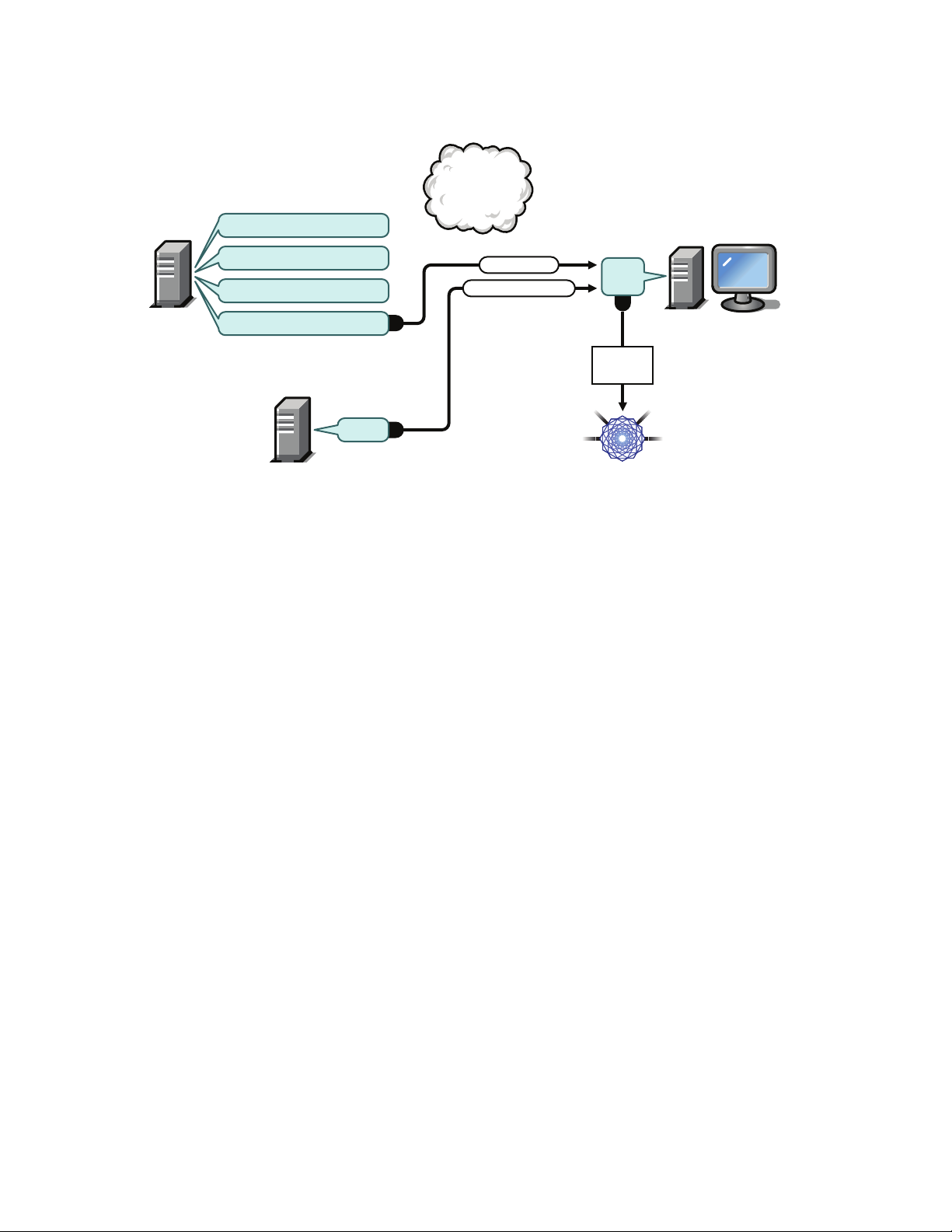
Figure 1-1 DHCP Configuration on Separate Servers
2
Imaging
Server
PXE Device
novell-proxydhcp
novell-tftp
novell-pbserv
PXE
BIOS
Data
Model
nvlnbp.sys
2
1
DHCP
Request
Network
DHCP
novell-zmgprebootpolicy
port
67
port
68
port
68
IP Configuration
novdocx (en) 16 April 2010
Processes:
1. When the device boots, the PXE BIOS issues a DHCP request with PXE extensions. The
request is broadcast on port 67.
2. The DHCP server responds with IP configuration information on port 68, and the Proxy DHCP
server responds on port 68 with the name of the bootstrap program (
address of the TFTP service or daemon where it can be found.
3. Continue with “Phases 2 through 8: Continuing the Process” on page 30.
Standard DHCP and Novell Proxy DHCP Configured on the Same Server: Part A
For this example, the DHCP server and the Preboot Services Imaging Server are configured on the
same server on the network. See “Standard DHCP and Novell Proxy DHCP Configured on the Same
Server: Part B” on page 29 for the second part of this example.
nvlnbp.sys
) and the IP
28 ZENworks 10 Configuration Management Preboot Services and Imaging Reference
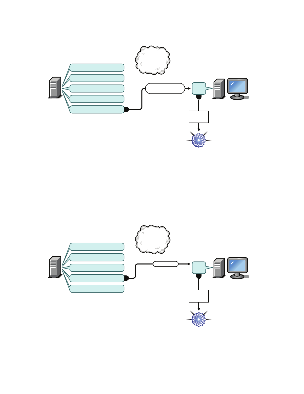
Figure 1-2 DHCP Configuration on the Same Server, Part A
2
Imaging
Server
PXE Device
novell-proxydhcp
novell-tftp
novell-pbserv
PXE
BIOS
Data
Model
1
DHCP
Request
Network
DHCP
novell-zmgprebootpolicy
port
67
port
68
IP Configuration &
Tag 60: PXEClient
Imaging
Server
PXE Device
novell-proxydhcp
novell-tftp
novell-pbserv
PXE
BIOS
Data
Model
nvlnbp.sys
2
1
DHC P
Request
Network
DHCP
novell-zmgprebootpolicy
port
4011
port
68
novdocx (en) 16 April 2010
Processes:
1. When the device boots, the PXE BIOS issues a DHCP request with PXE extensions. The
request is broadcast on port 67.
2. The DHCP server responds with IP configuration information on port 68, including tag 60 for
PXEClient, which indicates that novell-proxydhcp is running on the same server.
Standard DHCP and Novell Proxy DHCP Configured on the Same Server: Part B
Figure 1-3 DHCP Configuration on the Same Server, Part B
Overview 29
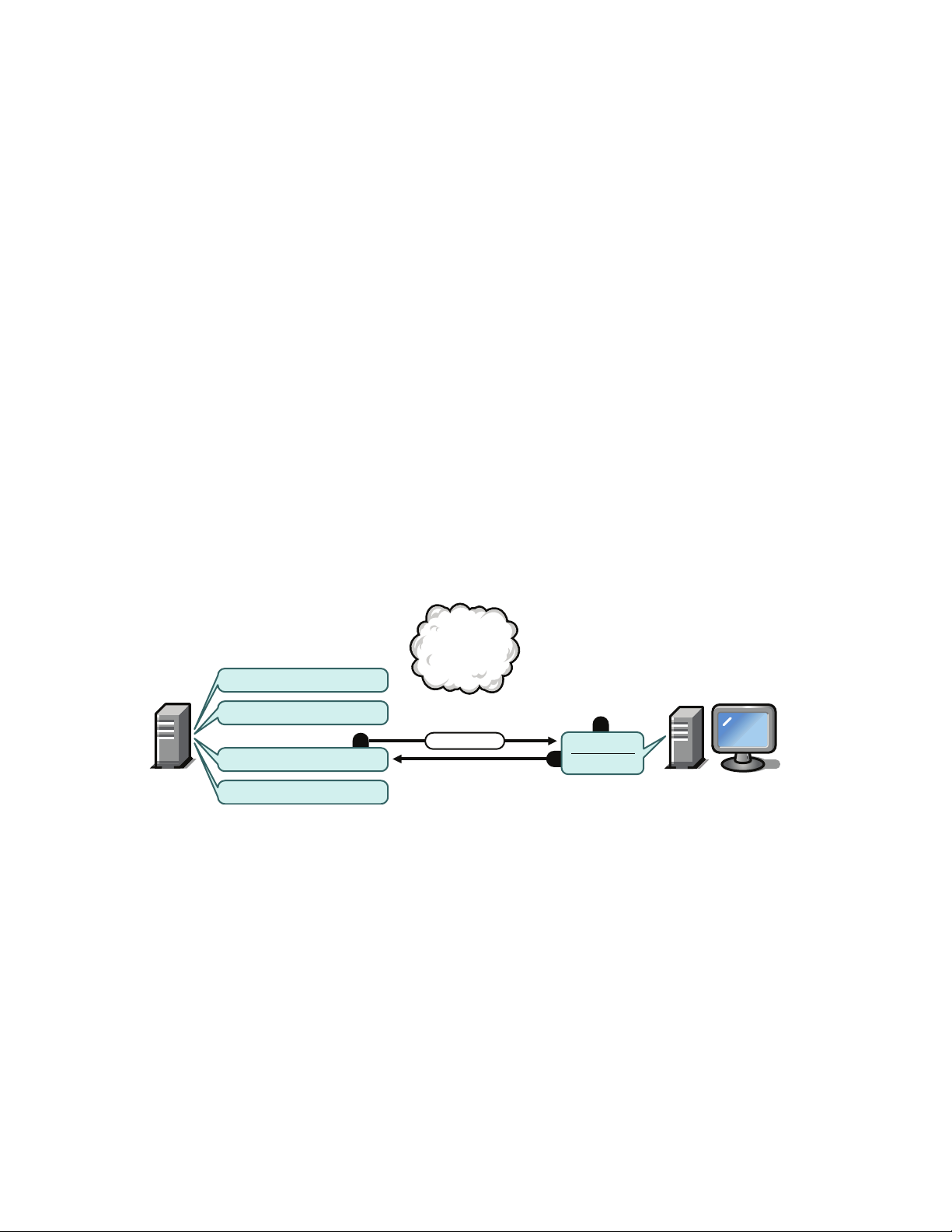
Processes:
3
1
2
Imaging
Server
PXE Device
Data
Model
novell-proxydhcp
novell-zmgprebootpolicy
novell-tftp
novell-pbserv
nvlnbp.sys
nvlnbp.sys
PXE BIOS
1. When the device sees tag 60 in the DHCP response, the PXE BIOS reissues the DHCP request
on port 4011.
2. The Proxy DHCP server responds on port 68 with the name of the bootstrap program
(
nvlnbp.sys
) and the IP address of the TFTP service or daemon where it can be found.
3. Continue with “Phases 2 through 8: Continuing the Process” on page 30.
Phases 2 through 8: Continuing the Process
The following sections explain how the Preboot Services process continues after Phase 1:
“Phase 2” on page 30
“Phase 3” on page 31
“Phase 4” on page 31
“Phase 5” on page 32
“Phase 6” on page 32
novdocx (en) 16 April 2010
“Phase 7” on page 33
“Phase 8” on page 33
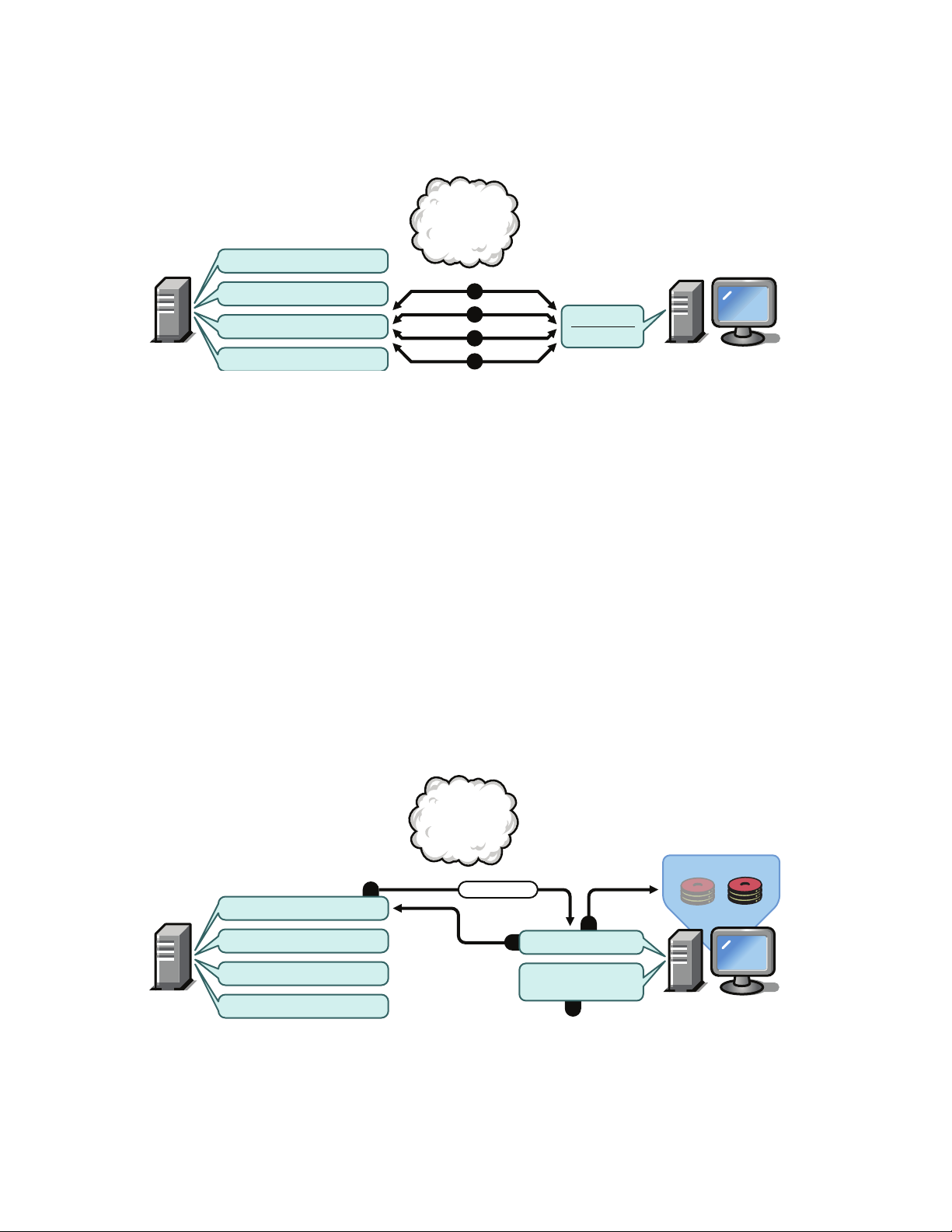
Phase 2
Figure 1-4 Phase 2 of the Preboot Services Process
Processes:
1. The PXE BIOS requests
2. The TFTP server sends
3. The PXE device loads
nvlnbp.sys
nvlnbp.sys
nvlnbp.sys
from the TFTP server.
to the PXE device.
into memory.
30 ZENworks 10 Configuration Management Preboot Services and Imaging Reference

Phase 3
2
3
Imaging
Server
PXE Device
Data
Model
novell-proxydhcp
novell-zmgprebootpolicy
novell-tftp
novell-pbserv
PXE Menu?
1
nvlnbp.sys
PXE BIOS
Hot-key:
pxemenu.text
2
Imaging
Server
PXE Device
Data
Model
novell-proxydhcp
novell-zmgprebootpolicy
novell-tftp
novell-pbserv
Yes: z_auto.cfg
1
nvlnbp.sys
PXE BIOS
Preboot work
to do?
Figure 1-5 Phase 3 of the Preboot Services Process
novdocx (en) 16 April 2010
Processes:
1. Hardware detection is performed by
2.
Nvlnbp.sys
requests the Novell Preboot Services Menu configuration from the Data Model
nvlnbp.sys
and it reads the image-safe data.
via novell-zmgprebootpolicy.
3. Novell-zmgprebootpolicy returns the Novell Preboot Services Menu configuration. In this
case, the menu described in
pxemenu.txt
is displayed when a user presses the hot key.
Phase 4
Figure 1-6 Phase 4 of the Preboot Services Process
Overview 31

Processes:
2
Imaging
Server
PXE Device
Data
Model
novell-proxydhcp
novell-zmgprebootpolicy
novell-tftp
novell-pbserv
pxelinux.0
1
nvlnbp.sys
PXE BIOS
2
1
Imaging
Server
PXE Device
Data
Model
novell-proxydhcp
novell-zmgprebootpolicy
novell-tftp
novell-pbserv
z_auto.cfg
z_auto.cfg
pxelinux.0
PXE BIOS
1. Assuming no Novell Preboot Services Menu is displayed, the device asks the Data Model (via
novell-zmgprebootpolicy) if any work is assigned.
2. Assuming work is assigned, novell-zmgprebootpolicy responds with the name of the
configuration file to use in performing the preboot work (
as shown in the above illustration and
winpe.cfg
for ZENworks Third-Party Imaging).
z_auto.cfg
for ZENworks Imaging
Phase 5
Figure 1-7 Phase 5 of the Preboot Services Process
novdocx (en) 16 April 2010
Processes:
1. The PXE device requests
2. The TFTP server sends
pxelinux.0
pxelinux.0
from the TFTP server.
to the device.
Phase 6
Figure 1-8 Phase 6 of the Preboot Services Process
Processes:
1. Pxelinux.0 replaces
for ZENworks Imaging (as shown in the above illustration) and
Third-Party Imaging.
2. The TFTP server sends the
32 ZENworks 10 Configuration Management Preboot Services and Imaging Reference
ZENworks Third-Party Imaging to the device.
nvlnbp.sys
in memory, and requests
z_auto.cfg
file for ZENworks Imaging and
z_auto.cfg
from the TFTP server
winpe.cfg
for ZENworks
winpe.cfg
for
Phase 7
Imaging
Server
PXE Device
Data
Model
novell-proxydhcp
novell-zmgprebootpolicy
novell-tftp
novell-pbserv
1
2
3
4
pxelinux.0
PXE BIOS
3
3
2
Imaging
Server
PXE Device
novell-proxydhcp
novell-zmgprebootpolicy
novell-tftp
SUSE Linux
EnterpriseServer
Data
Model
1
novell-pbserv
Imaging Engine
Image
image.zmg
Figure 1-9 Phase 7 of the Preboot Services Process
Processes for ZENworks Imaging (as shown in the above illustration):
1.
Pxelinux.0
2.
Pxelinux.0
3.
Pxelinux.0
requests and receives
requests and receives
requests and receives
/boot/kernel
/boot/initrd
/boot/root
from the TFTP server.
from the TFTP server.
from the TFTP server.
novdocx (en) 16 April 2010
Pxelinux.0
4.
requests and receives
/boot/updateDrivers.tgz
from the TFTP server, but is
denied because the file does not exist (it is used to provide post-release software updates).
Processes for ZENworks Third-Party Imaging:
Pxelinux.0
1.
2.
Pxeboot.0
3. The boot manager loads
4. The boot manager finally receives and loads
requests and receives
requests and receives
/boot/bcd
/boot/preboot.0
/boot/bootMgr.exe
.
/boot/boot.sdi
from the TFTP server.
from the TFTP server.
and
/boot/winpe.wim
Phase 8
Figure 1-10 Phase 8 of the Preboot Services Process for ZENworks Imaging
.
Processes for ZENworks Imaging:
1. SUSE
®
Linux Enterprise Server (SLES) is loaded and run on the device.
Overview 33

novdocx (en) 16 April 2010
3
2
Imaging
Server
Shared Image
Repository
PXE Device
novell-proxydhcp
novell-zmgprebootpolicy
novell-tftp
WINPE
Data
Model
1
novell-pbserv
Work To Do App
Image
image.wim
2. The ZENworks Imaging Engine (
img
) requests the assigned Preboot Services work details and
performs the work.
3. The image is laid down on the device and it automatically reboots.
Figure 1-11 Phase 8 of the Preboot Services Process for ZENworks Third-Party Imaging
Processes for ZENworks Third-Party Imaging:
1. WinPE distro is loaded and run on the device.
2. The Novell ZENworks Third Party Imaging utility requests the assigned Preboot Services work
details and performs the work.
3. The image is laid down on the device and it automatically reboots.
1.5 Preboot Strategies
The following sections present possible approaches to using Preboot Services. Use the following
sections to determine which procedures to perform. The steps are documented in subsequent
sections.
Section 1.5.1, “Automating Imaging Tasks,” on page 34
Section 1.5.2, “Creating, Installing, and Restoring Standard Images,” on page 35
Section 1.5.3, “Reimaging Corrupted Devices,” on page 36
Section 1.5.4, “Restoring Lab Devices to a Clean State,” on page 36
Section 1.5.5, “Setting Up Devices for Future Reimaging,” on page 37
Section 1.5.6, “Multicasting Device Images,” on page 37
1.5.1 Automating Imaging Tasks
You can automate imaging tasks in the following ways:
Imaging Script Execution: The Imaging Script bundle can automate execution of an Imaging
Device Imaging: The ZENworks Image bundle can be used to place an image on a device.
Script on a managed device, including imaging commands. This is applicable only for
ZENworks Imaging.
34 ZENworks 10 Configuration Management Preboot Services and Imaging Reference

Imaging Multiple Devices: The Multicast Image Set bundle can be used to place an image on
multiple devices with one pass of the image file over the network, such as in resetting lab
devices. This is applicable only for ZENworks Imaging.
All you need to do to accomplish any of these actions is to create and configure one of the Imaging
bundle types, then assign the bundle to the desired devices. When a device boots, the assigned
bundle is automatically applied before the device’s operating system starts.
You can also manually accomplish these tasks per device using the Novell Preboot Services Menu’s
Start ZENworks Imaging Maintenance option to access the imaging maintenance mode prompt, if
you have enabled the menu for the device. Or, you can use a Preboot Services bootable CD or DVD,
which does not require PXE to be enabled on the device. For more information, see Section 3.1.2,
“Using the Command Line for ZENworks Imaging,” on page 107.
1.5.2 Creating, Installing, and Restoring Standard Images
As new devices are purchased and before deploying them, you can install a standard software
platform and enable the device for future unattended reimaging.
1. Create a model device of each type that you intend to deploy.
2. Create an image of each model device on a ZENworks Imaging Server. For more information,
see “Manually Taking an Image of a Device” on page 107.
novdocx (en) 16 April 2010
These images should include the Novell ZENworks Configuration Management Imaging
Agent (novell-ziswin).
3. Optionally, you can create a preboot imaging bundle for this image. This allows the image to be
assigned automatically for later use.
4. If you are using Preboot Services, install Configuration Management on a server, which makes
it an Imaging Server. For more information, see Section 2.1, “Preparing a Preboot Services
Imaging Server,” on page 41.
or
If you are using a bootable CD or DVD, or a ZENworks partition, create a boot CD or DVD
that points to the ZENworks Imaging Server where the model images are stored. For more
information, see Section 2.3, “Setting Up the Preboot Services Methods for ZENworks
Imaging,” on page 46.
As each new device comes in, do the following if you are using Preboot Services:
1. Make sure the device is PXE capable. Enable PXE if it isn’t enabled by default. For more
information, see Section 2.7, “Enabling PXE on Devices,” on page 96.
2. Physically connect the device to the network.
3. Boot the device from the Preboot Services Imaging Server.
If you are not using Preboot Services, boot the device with the imaging boot CD or DVD and
consider installing the ZENworks partition to enable auto-imaging without the CD or DVD. For
more information, see Step 3 on page 57 of Section 2.8.2, “Enabling a Device for Imaging
Operations,” on page 98. After you have installed the partition, reboot the device from the
ZENworks partition.
Overview 35

1.5.3 Reimaging Corrupted Devices
Without data loss or undue disruption to users, you can fix devices that have become misconfigured
or corrupted.
1. When a device needs to be fixed, have the user back up any files to the network that he or she
wants to keep (if possible).
2. Create and/or assign an appropriate imaging bundle to the device.
3. If it is a device with a ZENworks partition or if it is PXE-enabled, the user should boot the
device from the ZENworks partition or the Preboot Services Imaging Server (via PXE) to find
and execute the assigned bundle. If you are using PXE, make sure that Preboot Services is
installed on your server to make it an Imaging Server. For more information, see Chapter 3,
“Using Imaging,” on page 99.
or
If the device does not have a ZENworks partition and is not PXE-enabled, the user should boot
the device with the imaging boot CD or DVD and restore the appropriate images manually.
4. After the image is laid down, restore any user files that were backed up to the network.
novdocx (en) 16 April 2010
1.5.4 Restoring Lab Devices to a Clean State
You can restore devices to a clean state, removing any changes or additions made since the last time
you restored the image on that device. This is useful for updating lab devices.
For a method to initially set up a lab, see Section 1.5.6, “Multicasting Device Images,” on page 37.
The following steps assume that the devices are unregistered.
1. Create an image of a clean model device and store it on a ZENworks Imaging Server. For more
information, see “Manually Taking an Image of a Device” on page 107.
2. If you are using Preboot Services, make sure that Configuration Management is installed on
your server to make it an Imaging Server. For more information, see Section 2.1, “Preparing a
Preboot Services Imaging Server,” on page 41.
3. If you are using Preboot Services and the devices are PXE capable, make sure that PXE is
enabled. For more information, see Section 2.7, “Enabling PXE on Devices,” on page 96.
or
If you are not using Preboot Services or the ZENworks partition, create an imaging boot CD or
DVD that points to the ZENworks Imaging Server where the clean image is stored. For more
information, see Section 2.3, “Setting Up the Preboot Services Methods for ZENworks
Imaging,” on page 46.
Deploy each lab device as follows:
1. Physically connect the device to the lab network.
2. If you are using Preboot Services, boot the device from the Preboot Services Imaging Server.
or
If you are not using Preboot Services, boot the device with the imaging boot CD or DVD and
install the ZENworks partition. For more information, see Step 3 on page 57 of Section 2.8.2,
“Enabling a Device for Imaging Operations,” on page 98. After you have installed the partition,
reboot the device from the ZENworks partition.
36 ZENworks 10 Configuration Management Preboot Services and Imaging Reference

3. At the end of each lab session, assign the Imaging bundle to the lab devices.
4. Reboot each device and let it be auto-imaged by its assignment to a ZENworks Imaging
bundle.
1.5.5 Setting Up Devices for Future Reimaging
With minimal disruption to users, you can enable existing devices for future reimaging.
This process might need to be phased in by local administrators. Each administrator can do the
following:
1. Install the Novell ZENworks Configuration Management Imaging Agent (novell-ziswin) on
each device.
2. If the devices are PXE-capable, make sure PXE is enabled (see Section 2.7, “Enabling PXE on
Devices,” on page 96) and make sure that Configuration Management is installed on your
server to make it an Imaging Server (see Section 2.1, “Preparing a Preboot Services Imaging
Server,” on page 41).
or
Prepare a few sets of imaging CDs or DVDs that users can use when they have difficulty (see
Section 2.3, “Setting Up the Preboot Services Methods for ZENworks Imaging,” on page 46).
These devices should point to an Imaging Server that contains the same clean images used for
new devices.
3. If a user has difficulty, use the strategy for reimaging corrupted devices. For more information,
see Section 1.5.3, “Reimaging Corrupted Devices,” on page 36.
novdocx (en) 16 April 2010
1.5.6 Multicasting Device Images
The following sections explain the multicasting images feature for ZENworks Imaging:
“Understanding Multicasting” on page 37
“Practical Uses For Multicasting” on page 38
“Automatic Multicasting Example” on page 39
For instructions on using multicasting, see Section 3.2, “Multicasting Images for ZENworks
Imaging,” on page 122.
Understanding Multicasting
Multicasting is a way to send the same image to multiple devices without sending that image
multiple times across the network. It is done by inviting participants to join a multicast session.
Multicasting is similar to broadcasting on the network, because you send the image once to the
network and only those devices belonging to the multicast session can see and receive it. This saves
on network bandwidth usage.
For example, if you have 10 devices in the multicast session and the image is 3 GB in size, your
network experiences only 3 GB of network traffic to image all 10 devices. Without multicasting, the
network experiences 30 GB of network traffic to image all 10 devices individually.
Overview 37

The devices to be imaged must be physically connected to the network. They can be devices with
existing operating systems of any kind, or they can be new devices with no operating system
installed.
IMPORTANT: For multicasting to work properly, all routers and switches on the network must
have their multicast features configured. Otherwise, multicast packets might not be routed properly.
Multicasting can be done automatically or manually:
“Automatic Multicasting” on page 38
“Manual Multicasting” on page 38
Automatic Multicasting
In ZENworks Control Center, multicasting is accomplished by configuring a Multicast Image Set
bundle. The bundle contains a base image that is taken previously from a device and is stored on an
Imaging Server. This base image is applied to all multicast session participants.
When using an Imaging bundle to perform multicasting, the Imaging Server is the session master,
.zmg
which sends the
image file to the session participants. Novell-pbserv is used in this process.
All problems are reported and displayed on the session master device.
novdocx (en) 16 April 2010
For more information, see Section 3.2, “Multicasting Images for ZENworks Imaging,” on page 122.
Manual Multicasting
At the imaging maintenance mode prompt, you can enter commands to configure and initiate a
multicasting session. You enter the appropriate commands on the prompt at each device, specifying
one of them to be the session master. An image of the session master’s hard drive is sent to each of
the session participants.
For more information on the imaging commands, see Section F.5, “Session Mode (Multicast Image
Set),” on page 230.
If you plan to set up multicasting by visiting each device, you need either an imaging boot CD or
DVD, or the devices must be PXE-enabled. For more information, see Section 2.3, “Setting Up the
Preboot Services Methods for ZENworks Imaging,” on page 46.
Practical Uses For Multicasting
Multicasting is ideal for labs, classrooms, and staging areas, or for any place where you need to
quickly create the same configuration on multiple devices, instead of taking the time to set up each
device individually.
Benefits of Multicasting Images
Multicasting is the way to use ZENworks Imaging Engine for mass reimaging with the least amount
of overhead. It is useful if you have one device with a clean software configuration that you want to
duplicate on several other devices, or if you have a single image that you want to set up on multiple
devices.
38 ZENworks 10 Configuration Management Preboot Services and Imaging Reference

Limitations of Multicasting Images
One significant limitation of using multicast without installing any Configuration Management
software is that it results in a set of devices that have duplicate network identities. The IP addresses
(if the network is using static IP addressing) and device hostname are all the same and can cause
conflicts if deployed on the network without change.
For a handful of devices, this might not be a problem. But for a larger number of devices, you should
install the Novell ZENworks Configuration Management Imaging Agent (novell-ziswin) on each
device before doing the multicast (see Section 2.8.2, “Enabling a Device for Imaging Operations,”
on page 98). The Imaging Agent saves the device’s network identity settings before the multicast
session and restores them afterwards.
Automatic Multicasting Example
To automatically multicast an image to multiple devices using ZENworks Control Center:
1. In ZENworks Control Center, create a Multicast Image Set bundle using a wizard.
2. Specify the source image for the bundle.
You can multicast an existing image from your Imaging Server.
3. Configure the trigger for multicasting the bundle, as in the following examples:
Client Count: When the specified number of clients specified in the bundle have booted and
registered, the multicast session begins.
Time Count: When the specified length of time has passed with no new clients having
registered, the multicast session begins regardless of the number of client participating.
novdocx (en) 16 April 2010
The first trigger to be realized causes the multicast session to begin.
4. Assign the Multicast Image Set bundle to the desired devices.
ZENworks Control Center provides a way to enable or disable a Multicast Image Set bundle,
allowing you to temporarily stop the bundle from executing. This is more efficient than
unasssigning the bundle from many devices.
5. Wait for the trigger to happen.
Each device booting into the session has its boot process delayed until the session begins,
which is determined by fulfillment of one of the triggers.
The multicast happens automatically when a device assigned to the Multicast Image Set bundle
boots, according the configuration you set up for the Multicast Image Set bundle and for the
devices you assigned to the bundle. This bundle is applied to each session device before it
boots its operating system. The ZENworks Multicast Image Set bundle is sent over the wire
just once, using the multicast capability of your network, and executed simultaneously on all
participating devices.
Overview 39

novdocx (en) 16 April 2010
40 ZENworks 10 Configuration Management Preboot Services and Imaging Reference

2
Setting Up Preboot Services and
novdocx (en) 16 April 2010
Imaging
The section provides instructions for setting up Preboot Services in Novell® ZENworks® 10
Configuration Management:
Section 2.1, “Preparing a Preboot Services Imaging Server,” on page 41
Section 2.2, “Preparing a Satellite with the Imaging Role,” on page 42
Section 2.3, “Setting Up the Preboot Services Methods for ZENworks Imaging,” on page 46
Section 2.4, “Deploying and Managing Preboot Services,” on page 59
Section 2.5, “Configuring Preboot Services Defaults for ZENworks Imaging,” on page 73
Section 2.6, “Overriding Preboot Services Defaults,” on page 94
Section 2.7, “Enabling PXE on Devices,” on page 96
Section 2.8, “Setting Up Devices for ZENworks Imaging,” on page 97
IMPORTANT: The Preboot Services software is automatically installed when you install
ZENworks Configuration Management.
2.1 Preparing a Preboot Services Imaging Server
2
When you install Novell ZENworks Configuration Management on a server, the Preboot Service
service or daemon (novell-pbserv) makes all Primary Servers an Imaging Server. To avoid
confusion, the Proxy DHCP service or daemon (novell-proxydhcp) is installed, but not enabled. For
PXE devices to be able to communicate with Preboot Services, this service or daemon must be
started manually on at least one server on each network segment. Exactly how many servers and
which specific servers should run this service or daemon is dictated by your network topology. As a
rule of thumb, for every DHCP server deployed in your network, you should have a corresponding
Proxy DHCP server.
For information on setting up management of your devices, see Section 2.4, “Deploying and
Managing Preboot Services,” on page 59 and Section 2.5, “Configuring Preboot Services Defaults
for ZENworks Imaging,” on page 73.
In addition to the specific hardware requirements for a ZENworks Server, the server used to store
image files must meet the following requirements:
Fixed IP Address: When you connect to the Imaging Server during an imaging operation, you
must do so using the fixed IP address or DNS name of the Imaging Server.
Enough Space to Store Device Images: Unless you use compression (which is enabled by
default) for your device images, they are nearly the same size as the data on the device hard
disk, which could be many gigabytes.
If you want to store an image locally (on a CD, DVD, or hard disk) rather than on an Imaging
Server, see “Using a CD or DVD for Disconnected Imaging Operations” on page 117 and
“Using a Hard Disk for Disconnected Imaging Operations” on page 119.
Setting Up Preboot Services and Imaging
41

2.2 Preparing a Satellite with the Imaging Role
A Satellite is a managed device that can perform certain roles that a ZENworks Primary Server
normally performs. A Satellite can be any managed device (server or workstation). When you
configure a Satellite, you specify which roles it performs (Imaging, Collection, or Content). A
Satellite can also perform roles that might be added by third-party products that are snap-ins to the
ZENworks 10 Configuration Management framework.
The following sections provide detailed information:
Section 2.2.1, “Understanding the Imaging Role,” on page 42
Section 2.2.2, “Configuring the Imaging Role to the Satellite,” on page 42
Section 2.2.3, “Illustrating the Preboot Services Processes on the Imaging Satellite,” on
page 43
2.2.1 Understanding the Imaging Role
The Imaging role installs the Imaging services and adds the Imaging role to the device. The Satellite
with the Imaging role is called Imaging Satellite. The Imaging Satellite requires both Proxy DHCP
and DNS server to be running in the Imaging environment.
novdocx (en) 16 April 2010
The Imaging roles allows you to:
Perform all the Imaging operations on the device by using it as an Imaging server. The
operations includes taking an image and applying an image within as well as across subnets by
using unicast or multicast imaging.
Achieve load balance for the Primary Server.
Replicate add-on images to the Satellite.
The Satellite communicates with the Primary Server for the Imaging operations in the Auto mode
through ZENworks Control Center.
On the managed device, the Imaging module is inactive until you promote the managed device to be
a Satellite with the Imaging role or the Imaging role is added to an existing Satellite. This activates
the Imaging services on the device, and enables you to perform the Imaging operations in auto and
maintenance mode.
The Imaging components installed on the device include Novell ZENworks PXE Client Files,
Novell ZENworks PXE Update Files, and Novell ZENworks Multicast Application (zmgmcast).The
Imaging services installed on the device include Novell TFTP, ZENworks Preboot Policy
(zmgpbpolicy), ZENworks Preboot (pbserv), and Novell Proxy DHCP. All services, except for
proxy DHCP, are automatically started. You can manually start or stop the proxy DHCP service
from ZENworks Control Center.
2.2.2 Configuring the Imaging Role to the Satellite
You can configure the Imaging role to the Satellite by using ZENworks Control Center or the zman
command line utility.
42 ZENworks 10 Configuration Management Preboot Services and Imaging Reference

To configure the Imaging role by using ZENworks Control Center, see “Satellites” in the ZENworks
10 Configuration Management System Administration Reference. To configure the Imaging role by
using the zman command line utility, see “Satellite Commands” in the ZENworks 10 Configuration
Management Command Line Utilities Reference.
2.2.3 Illustrating the Preboot Services Processes on the Imaging Satellite
A typical Preboot Services operation for Imaging Satellite flows as follows:
1. An Imaging bundle is created in ZENworks Control Center and assigned to a PXE-enabled
device.
2. The PXE-enabled device starts to boot.
3. The device sends a DHCP discovery request to determine the IP address of the Imaging
Satellite.
4. The DHCP server responds with an IP address for the device to use.
5. Novell-proxydhcp responds with the IP addresses of the TFTP server, as well as the filename of
the Preboot Services bootstrap program (
nvlnbp.sys
).
novdocx (en) 16 April 2010
6. The PXE device downloads the Preboot Services bootstrap program by using novell-tftp on
Imaging Satellite.
7. After the Preboot Services bootstrap program is downloaded and executed, the device checks
for the novell-zmgprebootpolicy on Imaging Satellite to see if there is any imaging work to do.
8. If there is imaging work to do (as contained in an Imaging bundle that is assigned to the
device), the device downloads the WinPE environment from the server.
9. Any imaging tasks contained in the Imaging bundle are performed.
10. If there are no imaging tasks to perform, files are not downloaded and the device proceeds to
boot to its operating system.
All database transactions for assigned imaging tasks are performed through a web request from the
Imaging Satellite to the Primary Server.
The following sections explain how the Preboot Services work for PXE boot, ZENworks Imaging,
and third-party imaging on the Imaging Satellite:
“Illustrating the Preboot Services Process for PXE Boot on the Imaging Satellite” on page 43
“Illustrating the Preboot Services Process for ZENworks Imaging on the Imaging Satellite” on
page 44
“Illustrating the Preboot Services Process for Third-Party Imaging on the Imaging Satellite” on
page 45
Illustrating the Preboot Services Process for PXE Boot on the Imaging Satellite
The following example assumes that the devices and Imaging Servers are in the same network
segment.
Setting Up Preboot Services and Imaging 43

Figure 2-1 Preboot Services Process for PXE Boot on the Imaging Satellite
Primary
Server
PXE Device
Network
Imaging
Server
novell-tftp
novell-zmgprebootpolicy
novell-pbserv
novell-proxydhcp
novell-tftp
DHCP
PXE
BIOS
novell-zmgprebootpolicy
port
68
port
68
2
1
2
novell-pbserv
novell-proxydhcp
Web
Request
Data model
nvlnbp.sys
IP Configuration
DHCP
Request
port
67
novdocx (en) 16 April 2010
Processes:
1. When the device boots, the PXE BIOS issues a DHCP request with PXE extensions. The
request is broadcast on port 67.
2. The DHCP server responds with IP configuration information on port 68, and the Proxy DHCP
server on Imaging Satellite responds on port 68 with the name of the bootstrap program
nvlnbp.sys
(
Illustrating the Preboot Services Process for ZENworks Imaging on the Imaging
Satellite
The following example assumes that the devices and Imaging Servers are in the same network
segment.
) and the IP address of the TFTP service or daemon where it can be found.
44 ZENworks 10 Configuration Management Preboot Services and Imaging Reference

Figure 2-2 Preboot Services Process for ZENworks Imaging on the Imaging Satellite
Primary
Server
PXE Device
Imaging
Server
Image
novell-tftp
novell-zmgprebootpolicy
novell-pbserv
novell-proxydhcp
novell-zmgprebootpolicy
novell-pbserv
Imaging Engine
SUSE Linux Enterprise Server
332
1
novell-tftp
novell-proxydhcp
Web
Request
Data model
image.zmg
novdocx (en) 16 April 2010
Processes:
1. SUSE Linux Enterprise Server (SLES) is loaded and run on the device.
2. The ZENworks Imaging Engine (img) requests the assigned Preboot Services work details and
performs the work.
3. The image is laid down on the device and it automatically reboots.
Illustrating the Preboot Services Process for Third-Party Imaging on the Imaging
Satellite
For ZENworks Third-Party imaging, you must upload the third-party tools on the Primary Server.
For more information, see Section D.2, “Performing ZENworks Third-Party Imaging by Using
ZENworks Control Center,” on page 168. This automatically replicates the required imaging distro
and tools from the Primary Server to the corresponding tftp directory on the Imaging Satellite. The
imaging process on the Imaging Satellite is similar to the process on the Primary Server. For more
information on the imaging process on the Primary Server, see, Section 1.4, “The Preboot Services
Processes,” on page 26.
The following example assumes that the devices and Imaging Servers are in the same network
segment.
Setting Up Preboot Services and Imaging 45

Figure 2-3 Preboot Services Process for Third-Party Imaging on the Imaging Satellite
Primary
Server
PXE Device
Imaging
Server
Image
novell-tftp
novell-zmgprebootpolicy
novell-pbserv
novell-proxydhcp
novell-zmgprebootpolicy
novell-pbserv
Work To Do App
WINPE
332
1
novell-tftp
novell-proxydhcp
Web
Request
Data model
image.wim
novdocx (en) 16 April 2010
Processes:
1. WinPE is loaded and run on the device.
2. The ZENworks Work To Do (ZENworks Third-Party Imaging) application requests the
assigned Preboot Services work details and launches corresponding third-party Imaging engine
to perform the work.
3. The image is laid down on the device and it automatically reboots.
2.3 Setting Up the Preboot Services Methods for ZENworks Imaging
The Novell ZENworks Imaging Engine that performs the actual imaging of a device is a Linux
application. Unless you use automated Preboot Services with PXE-enabled devices, you need to
prepare a boot medium that has the Linux kernel, ZENworks Imaging Engine, and network drivers
installed.
The following sections contain additional information:
Section 2.3.1, “Using Preboot Services (PXE),” on page 47
Section 2.3.2, “Preparing Imaging Boot CDs or DVDs,” on page 47
Section 2.3.3, “Configuring with ZENworks Imaging Media Creator,” on page 49
Section 2.3.4, “Managing ZENworks Partitions,” on page 56
46 ZENworks 10 Configuration Management Preboot Services and Imaging Reference

2.3.1 Using Preboot Services (PXE)
Preboot Execution Environment (PXE) is an Intel specification that allows a device to boot from the
network, instead of its hard drive or other local media. Configuration Management can use PXE to
launch Preboot Services.
Preboot Services uses PXE to find out if there is imaging work specified for a device and to provide
the device with the files necessary to boot to the ZENworks imaging environment.
Before you can use Preboot Services with automated Imaging bundles, you need to do the
following:
1. Install ZENworks Configuration Management on your Imaging Server.
2. Enable PXE on the device.
3. Have a standard DHCP server, either on your Imaging Server or on another network server.
Automated Preboot Services functions can also be performed using a ZENworks partition. For more
information, see “Creating a ZENworks Partition” on page 56.
Manual Preboot Services functions can be performed using CDs or DVDs. For more information,
see Section 2.3.2, “Preparing Imaging Boot CDs or DVDs,” on page 47.
novdocx (en) 16 April 2010
2.3.2 Preparing Imaging Boot CDs or DVDs
If you have software for burning CDs or DVDs, you can create an imaging boot CD or DVD for
imaging operations. You have two options:
“Creating a Boot CD or DVD with Additional Files” on page 47
“Creating a Boot CD or DVD without Additional Files” on page 49
For information on how to use the CD or DVD to perform disconnected imaging operations, see
Section 3.1.3, “Setting Up Disconnected Imaging Operations,” on page 117.
Creating a Boot CD or DVD with Additional Files
This section describes how to create an imaging CD or DVD that contains more than the files
provided in the
bootcd.iso
This method allows you to include the
required imaging parameters. For more information on the
“Imaging Configuration Parameters (settings.txt),” on page 203.
This method also allows you to add other files and drivers that you need to do the imaging.
To create an imaging boot CD or DVD that includes
1 Copy the
bootcd.iso
image.
settings.txt
settings.txt
file to a temporary location.
file on the boot CD or DVD to provide the
settings.txt
file, see Section E.6,
and other files:
On the Imaging Server where ZENworks is installed, the
Windows:
Linux:
2 In an ISO editor, open the temporary copy of the
%ZENWORKS_HOME%\bin\preboot\
/opt/novell/zenworks/preboot/bin/winutils/
bootcd.iso
bootcd.iso
file is located in:
file.
Setting Up Preboot Services and Imaging 47

If you experience ISO corruption after adding files into the ISO, such as a checksum error, use
a more reliable ISO editor. Also, some ISO editors do not work very well with DVDs.
3 Using the temporary
bootcd.iso
image.
bootcd.iso
file, copy the
settings.txt
file to the root of the
novdocx (en) 16 April 2010
On the Imaging Server where ZENworks is installed, the
Windows:
Linux:
%ZENWORKS_HOME%\bin\preboot\
/opt/novell/zenworks/preboot/bin/winutils/
settings.txt
4 Copy any other files or drivers that you want included on the CD or DVD to the
directory in the temporary
bootcd.iso
Any files or subdirectories that you add under the
image.
/addfiles
directory are placed at the root of
file is located in:
addfiles
the client when booting the CD or DVD.
IMPORTANT: When booting from the CD or DVD, the imaging engine is read into RAM.
Because the imaging engine uses some of the RAM that exists on the client device, the
combined size of any files that you add under the
addfiles
directory cannot exceed the
amount of remaining RAM.
5 Save the updated
6 Use your software for burning CDs or DVDs to burn the updated
bootcd.iso
image file to its temporary location.
bootcd.iso
image onto the
CD or DVD.
7 Boot the device to be imaged from your newly created imaging boot CD or DVD.
Booting from a SCSI CD-ROM device is currently not supported.
To create an imaging boot CD or DVD by changing the default menu option in the
loader/isolinux.cfg
file.
/boot/i386/
1 Copy the
On the Imaging Server where ZENworks is installed, the
Windows:
Linux:
2 In an ISO editor, open the temporary copy of the
bootcd.iso
%ZENWORKS_HOME%\bin\preboot\
/opt/novell/zenworks/preboot/bin/winutils/
file to a temporary location.
bootcd.iso
bootcd.iso
file is located in:
file.
If you experience ISO corruption after adding files into the ISO, such as a checksum error, use
a more reliable ISO editor. Also, some ISO editors do not work very well with DVDs.
3 In the temporary
bootcd.iso
file, open the isolinux.cfg file located in the /boot/i386/loader
directory.
4 Edit the isolinux.cfg file to change the following line
default linux
to
default manual
5 Save the updated
6 Use your software for burning CDs or DVDs to burn the updated
bootcd.iso
image file to its temporary location.
bootcd.iso
image onto the
CD or DVD.
7 Boot the device to be imaged from your newly created imaging boot CD or DVD.
Booting from a SCSI CD-ROM device is currently not supported.
48 ZENworks 10 Configuration Management Preboot Services and Imaging Reference

The zmgbootcd imaging utility is available at the following locations:
https://primary_server_ID/zenworks-downloads/msi/novell-zenworks-zmgbootcd-
10.3.0.xxxxx.msi
https://primary_server_ID/zenworks-downloads/rpm/novell-zenworks-zmgbootcd-
10.3.0-xxxxx.i586.rpm
Creating a Boot CD or DVD without Additional Files
novdocx (en) 16 April 2010
If you do not want to include the
CD or DVD, you can simply create the imaging boot CD or DVD from the
settings.txt
file or any other files or drivers in the imaging boot
bootcd.iso
provided with ZENworks.
However, you need to provide the
settings.txt
imaging parameters. For more information on the
file on a floppy diskette to provide the required
settings.txt
file, see Section E.6, “Imaging
Configuration Parameters (settings.txt),” on page 203.
To create an imaging boot CD or DVD that contains only the
1 Copy the
settings.txt
file containing the settings you want for the imaging boot process
bootcd.iso
image:
onto a floppy diskette.
On the Imaging Server where ZENworks is installed, the
Windows:
Linux:
%ZENWORKS_HOME%\bin\preboot\
/opt/novell/zenworks/preboot/bin/winutils/
2 Use your software for burning CDs or DVDs to burn the
settings.txt
bootcd.iso
image onto the CD or
file is located in:
DVD.
On the Imaging Server where ZENworks is installed, the
Windows:
Linux:
%ZENWORKS_HOME%\bin\preboot\
/opt/novell/zenworks/preboot/bin/winutils/
bootcd.iso
file is located in:
3 Boot the device to be imaged from your newly created imaging boot CD or DVD.
You will be prompted for the diskette that contains the
settings.txt
file.
image
Booting from a SCSI CD-ROM device is currently not supported.
2.3.3 Configuring with ZENworks Imaging Media Creator
This utility allows you to create a bootable diskette for Preboot Services imaging functions in
ZENworks Configuration Management. For example, you can do the following:
Modify the
Create a bootable diskette to enable booting a device from a CD or DVD when it normally
cannot do so
Create a Preboot Bootable Image (PBI) file from a bootable diskette
IMPORTANT: This utility is a .NET application, and therefore requires the .NET framework to be
installed on the Windows device being used to run it.
For more information, see:
“ZENworks Imaging Media Creator Features” on page 50
settings.txt
file
Setting Up Preboot Services and Imaging 49

“Managing the Settings.txt File” on page 50
“Creating a Bootable Diskette” on page 54
“Creating a Preboot Bootable Image” on page 55
ZENworks Imaging Media Creator Features
The ZENworks Imaging Media Creator utility dialog box contains two tabs:
“CD Media Boot” on page 50
“Preboot Bootable Image” on page 50
CD Media Boot
The CD Media Boot tab allows you to make an image of a bootable diskette suitable for use with
PXE devices. You can:
Create a bootable diskette to enable booting devices with a CD or DVD (when they normally
can’t do so) to perform imaging tasks
novdocx (en) 16 April 2010
Specify configuration settings that are saved in the
settings.txt
file on the bootable diskette,
which are used when you boot devices with the diskette
Modify the configuration settings after creating the bootable diskette by editing the
settings.txt
file contained on the diskette
For more information, see “Creating a Bootable Diskette” on page 54.
Preboot Bootable Image
You can create a PXE Linux configuration file that points to a Preboot Bootable Image (PBI) file,
which is a raw image of a bootable diskette. This enables you to use PXE to utilize the bootable
.pbi
diskette information from a
file on a TFTP server, instead of booting from the diskette for that
Preboot information.
For more information, see “Creating a Preboot Bootable Image” on page 55.
Managing the Settings.txt File
There two
Windows:
settings.txt
Linux:
/srv/tftp/boot/
files shipped with Configuration Management:
%ZENWORKS_HOME%\share\tftp\boot\
PXE devices use this version of the file for automated preboot work. This file exists on the
Imaging Server and usually does not need to be modified. During the boot process, this
settings.txt
file is read and the necessary settings information is discovered and used.
Windows:
Linux:
%ZENWORKS_HOME%\bin\preboot\
/opt/novell/zenworks/zdm/winutils/
The Imaging Server copy of this file needs to be modified for your network environment and a
working copy of it should be maintained at the root of the imaging boot device (imaging CD or
DVD, or a blank floppy diskette). When burning the imaging CD or DVD, be sure to include
the edited copy of this
50 ZENworks 10 Configuration Management Preboot Services and Imaging Reference
settings.txt
file.
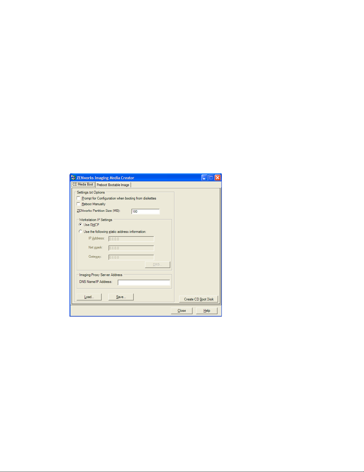
novdocx (en) 16 April 2010
You can manage the content of this copy of the
settings.txt
file with the ZENworks
Imaging Media Creator utility, as outlined in the following steps.
To manually edit the
settings.txt
file, see Section E.6, “Imaging Configuration Parameters
(settings.txt),” on page 203.
For more information, see Section E.6, “Imaging Configuration Parameters (settings.txt),” on
page 203.
To manage the
settings.txt
1 On a management device, run
Windows:
Linux:
%ZENWORKS_HOME%\bin\preboot\
/opt/novell/zenworks/zdm/winutils/
file using the ZENworks Imaging Media Creator utility:
zmediacreator.exe
from your Imaging Server:
For the Linux server path, to use a Windows management device to access to this directory you
might need to configure Samba.
The following dialog box is displayed:
2 Click Load, browse for and select the
The default location is
Windows:
Linux:
%ZENWORKS_HOME%\preboot\
/opt/novell/zenworks/zdm/winutils/
A:\
. Browse to the following directory for the copy to be modified:
settings.txt
file, then click Open.
When the file is loaded, the fields in this dialog box are populated from the information
contained in the
settings.txt
file.
3 (Optional) In the Settings.txt Options section on the CD Media Boot tab, fill in the fields:
Setting Up Preboot Services and Imaging 51

Prompt for Configuration When Booting from Diskette: Specifies whether to prompt for
these configuration settings when you boot a device with the bootable diskette and CD or
DVD. If you leave this option deselected, the device boots using the configuration settings that
you make here and you are not able to override the settings during bootup. If you select this
option, you are given the chance to change each setting during bootup.
Reboot Manually: Specifies whether you must reboot a device manually after it was booted
with the bootable diskette in automatic mode. (If the device was booted with the bootable
diskette in manual mode, you must always reboot the device manually.)
If you boot a device with the bootable diskette and you let the bootup process proceed in
automatic mode, the imaging engine starts and checks the Preboot server to see if an automatic
imaging operation should be performed. If so, it performs the imaging operation on the device
and quits. If not, it quits without doing anything. What happens next depends on whether you
select this option.
If you leave this option deselected, you are prompted to remove the bootable diskette and press
any key to reboot the device automatically to its native operating system. If you select this
option, the device doesn’t reboot automatically, but instead displays the imaging maintenance
mode prompt, allowing you to perform additional imaging-related tasks at the prompt. This is
helpful if you want to do things like check the current partition information or the image-safe
data before rebooting to the native operating system.
ZENworks Partition Size (MB): Specifies the number of megabytes to allocate to the
ZENworks partition if you choose to create one locally on a device when you boot the device
with the bootable diskette. The default size is 150 MB, which is the smallest you should make
the partition. The maximum size allowed is 2048 MB (2 GB).
4 (Optional) In the Workstation IP Settings section on the CD Media Boot tab, fill in the fields:
novdocx (en) 16 April 2010
Use DHCP: Specifies to obtain an IP address dynamically through DHCP. Use this option only
if DHCP is configured on your network.
Use the Following Static Address Information: Specifies to use a static IP address. If you
select this option, fill in the IP address, subnet mask, and gateway to be used.
DNS Button: This option is active only if a static IP address for the device is specified.
52 ZENworks 10 Configuration Management Preboot Services and Imaging Reference
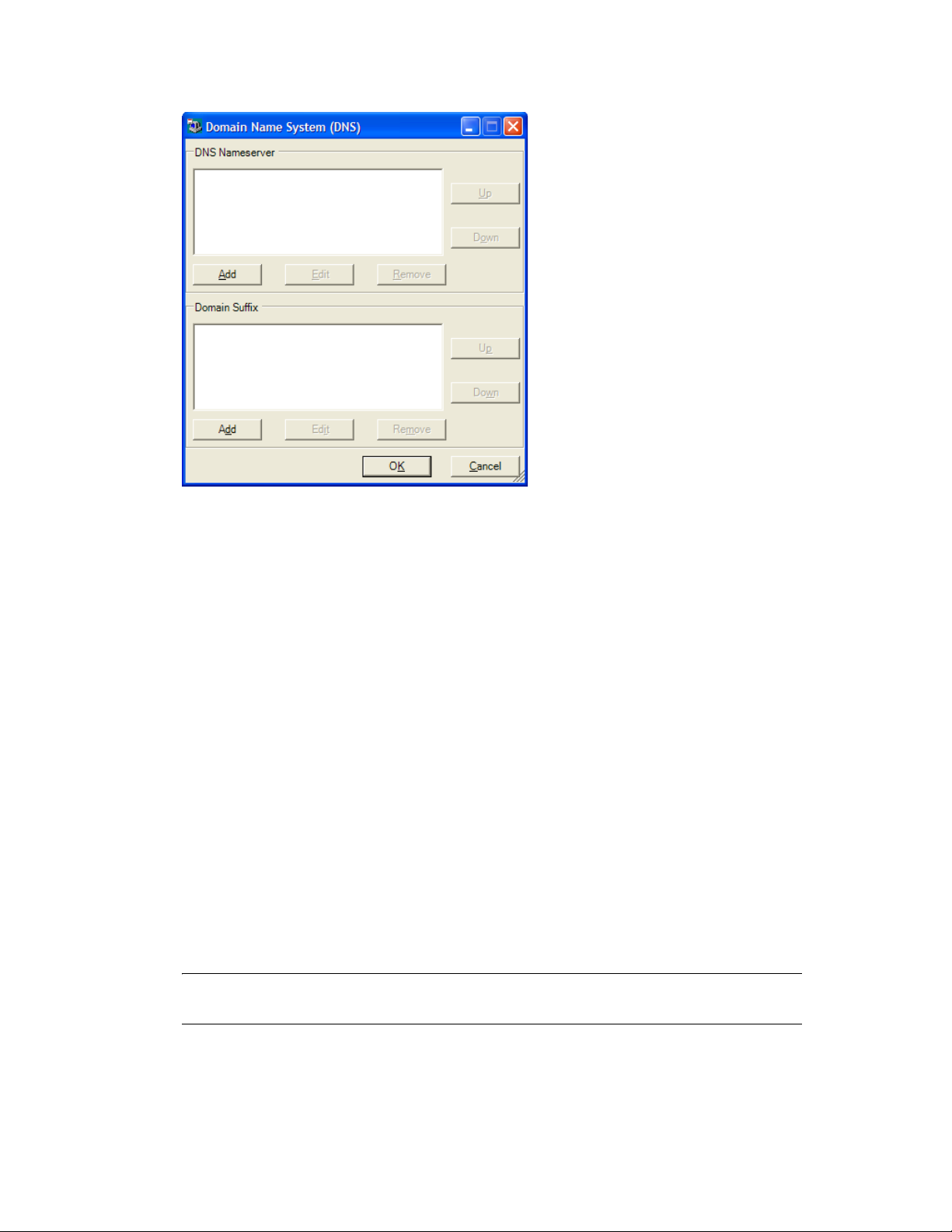
novdocx (en) 16 April 2010
DNS Nameserver: You must specify a nameserver if you want to use DNS to connect to
servers.
You can specify the addresses of as many DNS nameservers as you want. You can edit or
remove the nameserver addresses, or you can move the addresses up and down in the list
to specify the order used for contacting them.
Domain Suffix: You can also specify as many DNS domain suffixes as you want. The
editing, moving, and removal functions are also available for the suffixes.
5 (Required) In the Imaging Proxy Server Address section on the CD Media Boot tab, specify
either the fixed IP address or the full DNS name of Preboot server (where novell-pbserv is
running).
This specifies which Preboot server to connect to when you boot a device with the bootable
diskette.
Use a DNS name only if it is working on your network and the Imaging Server has an entry in
your DNS server’s name resolution table.
6 Click Save, browse for where you want to save the
settings.txt
Saves the configurations made in the Settings.txt Options section to the
A:\
the specified location. The default location is
, such as for a bootable diskette (see
file, then click Save.
settings.txt
file in
“Creating a Bootable Diskette” on page 54).
You can save to a different location for use in burning to an imaging CD or DVD.
7 When you are finished using this utility, click Close.
IMPORTANT: If you manually edit the
settings.txt
file to provide paths to executables,
make sure that you provide the full path, or the executable might not run.
Setting Up Preboot Services and Imaging 53
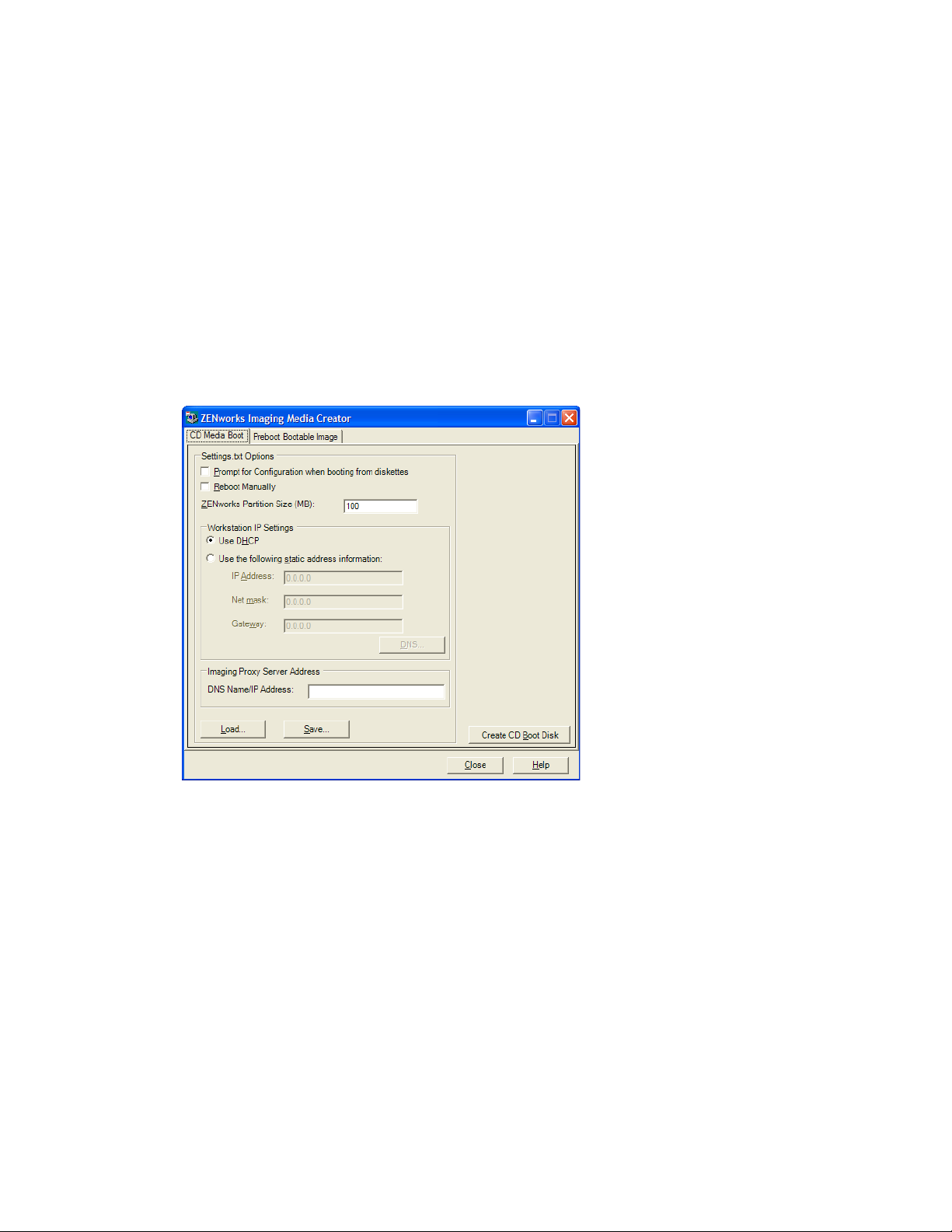
Creating a Bootable Diskette
If you have devices that cannot normally boot a CD or DVD, but has the CD or DVD hardware
installed, you can use the ZENworks Imaging Media Creator utility to create a diskette that enables
the device to boot from a CD or DVD.
To create a bootable diskette:
novdocx (en) 16 April 2010
1 On a management device, run
Windows:
Linux:
%ZENWORKS_HOME%\bin\preboot\
/opt/novell/zenworks/zdm/winutils/
zmediacreator.exe
from your Imaging Server:
For the Linux server path, to use a Windows management device to access to this directory you
might need to configure Samba.
The following dialog box is displayed:
2 If you want to modify a
settings.txt
file that is to be included on this diskette, follow Step 2
through Step 4 in “Managing the Settings.txt File” on page 50, then continue with Step 3 in this
section.
3 (Required) In the Imaging Proxy Server Address section on the CD Media Boot tab, specify
either the fixed IP address or the full DNS name of Preboot server (where novell-pbserv is
running).
This specifies which Preboot server to connect to when you boot a device with the bootable
diskette.
Use a DNS name only if it is working on your network and the Imaging Server has an entry in
your DNS server’s name resolution table.
4 Format one high-density diskette, or insert a preformatted blank diskette in the diskette drive of
the Windows device.
5 Click Create CD Boot Disk.
54 ZENworks 10 Configuration Management Preboot Services and Imaging Reference

This creates a bootable diskette that enables a device that cannot otherwise boot from a CD or
DVD to boot from the imaging CD or DVD. Any
settings.txt
configurations made here are
included in the copy written to the bootable diskette.
6 After the diskette is created, click Close.
7 Insert both this diskette and the imaging CD or DVD on the device to be imaged, then boot the
device.
The diskette enables the imaging CD or DVD to be booted by the device.
Creating a Preboot Bootable Image
You can create a PXE Linux configuration file that points to a Preboot Bootable Image (PBI) file,
which is a raw image of a bootable diskette. This enables you to use PXE to utilize the bootable
.pbi
diskette information from a
file on a TFTP server, instead of booting from the diskette for that
Preboot information.
To create a PBI configuration file and then the PBI file:
novdocx (en) 16 April 2010
1 On a management device, run
Windows:
Linux:
%ZENWORKS_HOME%\bin\preboot\
/opt/novell/zenworks/zdm/winutils/
zmediacreator.exe
from your Imaging Server:
For the Linux server path, to use a Windows management device to access to this directory you
might need to configure Samba.
The following dialog box is displayed after you click the Preboot Bootable Image tab:
2 In the Configuration File Settings section on the Preboot Bootable Image page, fill in the fields:
Kernel Parameters: To use the kernel parameters in the
keeppxe
option, select the Keep PXE
and UNDI Stacks in Memory option.
.pbi
PBI Filename: Specify a filename for the PBI file, including the
filename extension. Do
not specify a path here.
Setting Up Preboot Services and Imaging 55
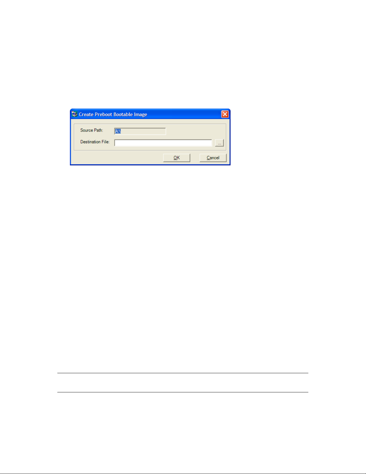
TFTP Relative Path: Specify the path for the PBI file, relative to the TFTP server’s default
path. This is where the PBI file will be accessed by the device booting with PXE.
Load: Load a previously defined PBI configuration file, which populates the fields on this
page with its information. You can edit those settings.
Save: Save the PBI configuration file to a location where you can access it again from this
dialog box.
3 To create the PBI file, click Create PBI and fill in the fields:
Source Path: Source of the information to be imaged to a PBI file. This is normally a bootable
diskette that was created on the CD Media Boot tab of this dialog box.
Destination File: Where the PBI file should be written. Browse for the location and type the
.pbi
PBI filename. The
filename extension is automatically added.
4 After the PBI is created, click Close.
This PBI file can now be used by a PXE-enabled device when booting so you can access
Preboot Services functionality as if you were booting the device with the bootable diskette.
novdocx (en) 16 April 2010
2.3.4 Managing ZENworks Partitions
A ZENworks partition is used by a device when booting for automated Preboot Services work when
the device does not have PXE available. The following sections explain how to manage ZENworks
partitions:
“Creating a ZENworks Partition” on page 56
“Disabling a ZENworks Partition” on page 57
“Removing a ZENworks Partition” on page 57
Creating a ZENworks Partition
If you want to set up a device for unattended imaging operations and are unable to use Preboot
Services (PXE), you can create a ZENworks partition on the hard disk. If you make the partition
large enough, you can even store an image of the device’s hard disk, which can be useful if the
device becomes misconfigured or corrupted when the network connection is lost.
WARNING: Installing the ZENworks partition destroys all data on that hard drive. Use this only on
devices where you plan to reinstall the operating system and software programs.
56 ZENworks 10 Configuration Management Preboot Services and Imaging Reference

To create a ZENworks partition, you must first create an imaging CD or DVD to boot the device
from. (If the device cannot boot from a CD or DVD, see Section 2.3.3, “Configuring with
ZENworks Imaging Media Creator,” on page 49.) Then, do the following:
1 Boot the device with the imaging CD or DVD, then select Install/Update ZEN partition from
the menu.
This starts the process of creating the ZENworks partition in the first partition slot. It destroys
all existing partitions, except an existing ZENworks partition or the Dell* or Compaq*
configuration partitions. By default, the ZENworks partition size is 150 MB.
If the ZENworks partition already exists, it is upgraded, and your existing partitions are left
intact.
2 After the ZENworks partition is installed or updated, remove the CD or DVD and press any
key to continue.
3 After removing the CD or DVD and reboot the device, install the operating system on the
device.
IMPORTANT: During installation of the operating system, you must install the boot loader
where the root (/) partition is being installed. In other words, the active partition must be the
root partition. You can use
fdisk
to verify that the active partition is root.
novdocx (en) 16 April 2010
4 To take an image of the device using the ZENworks partition, see “Using the Imaging
Maintenance Mode Prompt to Create an Image” on page 119.
5 When the imaging maintenance mode prompt is displayed, reboot the device.
The device should boot to Linux.
Disabling a ZENworks Partition
If you decide to enable PXE on a device, but have previously installed a ZENworks partition on it,
you can disable or delete the partition, because it is no longer necessary. For information on deleting
the partition, see “Removing a ZENworks Partition” on page 57.
When you boot to Linux using any imaging boot device or method other than booting from the
ZENworks partition, you can disable (or enable) the ZENworks partition. Just select the menu
option to do so when the Novell Preboot Services Menu is presented.
Removing a ZENworks Partition
Because you should not delete the ZENworks partition if you booted using the partition, you should
boot the device from an imaging boot method other than the ZENworks partition.
WARNING: After you have deleted the ZENworks partition, you need to make sure that the image
you place on the device was made on a device without a ZENworks partition. Otherwise, the wrong
MBR (Master Boot Record) is restored, and the device fails to boot. You should only remove the
ZENworks partition if you are going to restore an image that does not have the partition to the
device.
The following are ways you can remove a ZENworks partition from a device:
“Using an Imaging CD or DVD” on page 58
Setting Up Preboot Services and Imaging 57

“Using an Imaging Script Bundle” on page 58
“Using Fdisk” on page 58
Using an Imaging CD or DVD
If you cannot perform a full restoration of the ZENworks partition at this time, you should consider
removing it.
To remove a ZENworks partition:
1 Boot the device using the ZENworks imaging CD or DVD.
2 Select the Manual mode option.
3 At the imaging maintenance mode prompt, enter:
img -zenpart -remove
4 After the removal is complete, eject the CD or DVD (if you are not going to use it to reimage
the device).
5 If you want to restore an image before rebooting, enter the following at the prompt:
unset ZENDEVICE
Otherwise, reboot the device when ready.
6 Restore an image or install an operating system.
novdocx (en) 16 April 2010
When the device boots, its ZENworks partition is removed, then the device can be imaged from
the CD or DVD without a ZENworks partition.
If the device is assigned to an Imaging bundle, it is imaged according to that bundle.
Using an Imaging Script Bundle
If you are using Preboot Services, but formerly booted from the ZENworks partition on the device,
you can delete the ZENworks partition at the same time you restore an image. However, the new
image should not contain a ZENworks partition.
For example, you can do the following:
1 In ZENworks Control Center, create a Imaging Script bundle.
2 In the Script text field in the Create New Bundle Wizard, enter:
img -zenpart -remove
3 In the Script text field (after the above command), enter the other commands necessary for the
imaging work you want for the device.
For more information, see Appendix F, “ZENworks Imaging Engine Commands,” on page 217.
4 On the Summary page of the wizard, click Finish (not Next).
5 Reboot the device.
Using Fdisk
You can remove a ZENworks partition by simply using
fdisk
to reconfigure the device’s hard
drive. Then, you can either image the device using a ZENworks imaging CD or DVD, or enable
PXE on the device and assign an Imaging bundle to it, then reboot it to use that bundle.
58 ZENworks 10 Configuration Management Preboot Services and Imaging Reference

2.4 Deploying and Managing Preboot Services
The following sections explain how to set up, deploy, and manage Preboot Services, and how to set
up standard DHCP and novell-proxydhcp on the same server.
Section 2.4.1, “Checking the Preboot Services Imaging Server Setup,” on page 59
Section 2.4.2, “Deploying Preboot Services in a Network Environment,” on page 60
Section 2.4.3, “Administering Preboot Services,” on page 68
Section 2.4.4, “Editing the Novell Preboot Services Menu,” on page 71
For information on using Preboot, see Chapter 3, “Using Imaging,” on page 99.
2.4.1 Checking the Preboot Services Imaging Server Setup
This section provides information on how to check the configuration of Preboot Services after it is
installed.
“Overview of Preboot Services Components” on page 59
novdocx (en) 16 April 2010
“Checking the Setup” on page 60
Overview of Preboot Services Components
The following components are installed as part of Preboot Services:
Table 2-1 Preboot Service Components
Windows Executable
and Service Names
novell-pbserv.exe
Novell ZENworks
Preboot Service
novellproxydhcp.exe
Novell Proxy DHCP
Service
novell-tftp.exe
Novell TFTP Service
Linux Daemon Description
novell-pbserv Provides imaging services to devices.
novell-proxydhcp Runs alongside a standard DHCP server to inform
PXE devices of the IP address of the TFTP server.
The Proxy DHCP server also responds to PXE
devices to indicate which bootstrap program
nvlnbp.sys
(
novell-tftp Used by PXE devices to request files that are
needed to perform imaging tasks. The TFTP server
also provides a central repository for these imaging
files, such as the Linux kernel, initrd, and
nvlnbp.sys
) to use.
.
novellzmgprebootpolicy.
exe
Novell ZENworks
Preboot Policy Service
A PXE device uses this server to download the
bootstrap program (
novell-zmgprebootpolicy The PXE devices use this to check if there are any
Imaging bundles that are assigned to the device.
nvlnbp.sys
).
Setting Up Preboot Services and Imaging 59

Novell-proxydhcp must be started manually and does not need to be run on all Imaging Servers.
While taking an image, the novell-pbserv service must be running on the server where the
ZENworks image is to be stored. During restoring the image, the novell-pbserv service must be
running on the server where the ZENworks image is located.
The other three services are started automatically when installing Configuration Management, or
any time the server is rebooted, and must run on all Imaging Servers.
For more information, see Section E.8, “Imaging Server,” on page 206.
Checking the Setup
After the Preboot Services components are installed, the following should be installed and running
on the server. You can use these methods to check their status:
Table 2-2 Preboot Services Or Daemons
Service Method to Check Its Status
novell-pbserv Windows: In the Services dialog box, review the Status column of Novell
ZENworks Preboot Service.
novdocx (en) 16 April 2010
Linux:
/etc/init.d/novell-pbserv status
novell-tftp Windows: In the Services dialog box, review the Status column of Novell
TFTP Service.
/etc/init.d/novell-tftp status
Linux:
novell-zmgprebootpolicy Windows: In the Services dialog box, review the Status column of Novell
ZENworks Preboot Policy Service.
Linux:
/etc/init.d/novell-zmgprebootpolicy status
You should not change the default configuration of these services.
If the server where the Preboot Services components are installed is also a DHCP server, see
“Configuring LAN Environments for Preboot Services” on page 64.
2.4.2 Deploying Preboot Services in a Network Environment
To implement the network deployment strategies outlined in this section, you must have a solid
understanding of the TCP/IP network protocol and specific knowledge of TCP/IP routing and the
DHCP discovery process.
Deploying Preboot Services (with PXE) in a single network segment is a relatively simple process.
However, Preboot Services deployment in a multi-segment network is far more complex and might
require configuration of both the Preboot Services services or daemons and the network switches
and routers that lie between the server and the PXE devices.
Configuring the routers or switches to correctly forward Preboot Services network traffic requires a
solid understanding of the DHCP protocol, DHCP relay agents, and IP forwarding. The actual
configuration of the switch or router must be performed by a person with detailed knowledge of the
hardware.
60 ZENworks 10 Configuration Management Preboot Services and Imaging Reference

We strongly recommend that you initially set up Preboot Services in a single segment to ensure that
the servers are configured correctly and are operational.
This section includes the following information:
“Server Configuration” on page 61
“Network Configuration” on page 62
“Configuring Filters on Switches and Routers” on page 67
“Spanning Tree Protocol in Switched Environments” on page 68
Server Configuration
There are three important points about configuring servers for Preboot Services:
DHCP Server: The Preboot Services environment requires a standard DHCP server. It is up to
you to install your standard DHCP server.
Preboot Services or Daemons: The four Preboot Services services or daemons (novell-
pbserv, novell-tftp, novell-proxydhcp, and novell-zmgprebootpolicy) are all installed on the
Imaging Server when you install Configuration Management. These services or daemons must
run together on the same server.
Imaging Server: The Preboot Services services or daemons can be installed and run on the
same or different server than DHCP.
novdocx (en) 16 April 2010
The following sections give general information about these services:
“The DHCP Server” on page 61
“Novell-pbserv” on page 61
“Novell-proxydhcp” on page 62
“Novell-tftp” on page 62
“Novell-zmgprebootpolicy” on page 62
It is seldom necessary to make changes to the default configuration of these services. However, if
you need more detailed configuration information, see “Configuring Preboot Services Imaging
Servers” on page 68.
The DHCP Server
The standard DHCP server must be configured with an active scope to allocate IP addresses to the
PXE devices. The scope options should also specify the gateway or router that the PXE devices
should use.
If Preboot Services (specifically novell-proxydhcp) is installed on the same server as the DHCP
server, the DHCP server must be configured with a special option tag. For more information, see
“Configuring LAN Environments for Preboot Services” on page 64.
Novell-pbserv
Provides imaging services to devices.
This includes sending and receiving image files, discovering assigned Imaging bundles, acting as
session master for multicast imaging, and so on.
Setting Up Preboot Services and Imaging 61

Novell-proxydhcp
The Preboot Services Proxy DHCP server runs alongside a standard DHCP server to inform PXE
devices of the IP address of the TFTP server, the IP address of the server where novellzmgprebootpolicy is running, and the name of the network bootstrap program (
nvlnbp.sys
).
Novell-tftp
Used by PXE devices to request files that are needed to perform imaging tasks. The TFTP server
also provides a central repository for these files.
novdocx (en) 16 April 2010
A PXE device uses one of these servers to download the network bootstrap program (
nvlnbp.sys
Novell-zmgprebootpolicy
PXE devices use novell-zmgprebootpolicy to check if there are any imaging actions that need to be
performed on the device. It forwards requests to novell-pbserv on behalf of PXE devices.
If you are using Intel AMT, support for it should be enabled in the
zmgprebootpolicy.conf
Windows:
Linux:
%ZENWORKS_HOME%\conf\preboot\
/etc/opt/novell/zenworks/preboot/
file, which is located at:
novell-
Network Configuration
The configuration required to run Preboot Services in your network depends on your network setup.
Design your network so that PXE devices can effectively connect to the server where the Preboot
Services services or daemons are running. Make sure you consider the number of PXE devices to be
installed on the network and the bandwidth available to service these devices. To understand how
the devices and servers need to interact during the Preboot Services process, see Section 1.4, “The
Preboot Services Processes,” on page 26.
You can configure Preboot Services where Preboot Services and DHCP are running on the same
server or on different servers in both LAN and WAN/VLAN environments:
).
“Understanding Preboot Services in LAN and WAN/VLAN Environments” on page 62
“Comparing Preboot Services Setups in LAN and WAN/VLAN Environments” on page 63
“Configuring LAN Environments for Preboot Services” on page 64
“Configuring a WAN/VLAN with Preboot Services and DHCP Running on the Same Server”
on page 65
“Configuring a WAN/VLAN With Preboot Services and DHCP Running on Separate Servers”
on page 65
Understanding Preboot Services in LAN and WAN/VLAN Environments
Imaging servers should be installed so that PXE devices have access to imaging services within their
LAN. A good design ensures that a client does not need to connect to imaging services through a
slow WAN link.
Although you can have any number of Imaging Servers, generally only one Proxy DHCP server
should be enabled per DHCP server scope.
62 ZENworks 10 Configuration Management Preboot Services and Imaging Reference

In a WAN, the PXE device is usually separated from the Proxy DHCP and DHCP servers by one or
more routers. The PXE device broadcasts for DHCP information, but by default the router does not
forward the broadcast to the servers, causing the Preboot Services session to fail.
In a VLAN (Virtual LAN) environment, the PXE device is logically separated from the Proxy
DHCP server and the DHCP server by a switch. At the IP level, this configuration looks very similar
to a traditional WAN (routed) environment.
In a typical VLAN environment, the network is divided into a number of subnets by configuring
virtual LANs on the switch. Devices in each virtual LAN usually obtain their IP address information
from a central DHCP server. In order for this system to work, it is necessary to have Bootp or IP
helpers configured on each gateway. These helpers forward DHCP requests from devices in each
subnet to the DHCP server, allowing the DHCP server to respond to devices in that subnet.
Comparing Preboot Services Setups in LAN and WAN/VLAN Environments
The following illustrates the differences for a LAN configuration between installing Preboot
Services on the same server as DHCP, or on a separate server. In this case, only the PXE devices on
the LAN connect to the Preboot Services Imaging Server.
novdocx (en) 16 April 2010
Table 2-3 LAN Configuration Differences Between the Same and Separate Servers
Information On the Same Server On Separate Servers
Configuration Because Preboot Services and DHCP are
running on the same server, option tag 60
must be set on the DHCP server.
For information on setting this tag, see
“Configuring LAN Environments for
Preboot Services” on page 64.
Advantages
Easy installation and setup.
No network configuration is required.
None required.
Easiest installation and setup.
No network configuration is required.
No DHCP server configuration is
required.
Disadvantages
DHCP server configuration is
required (option tag 60).
Limited use, because a single-LAN
environment only exists in small labtype networks.
Limited use, because a single-LAN
environment only exists in small labtype networks.
The following illustrates the differences for a WAN/VLAN configuration between installing Preboot
Services on the same server as DHCP, or on a separate server. In this case, all PXE devices over the
entire WAN/VLAN connect to the Preboot Services Imaging Server.
Setting Up Preboot Services and Imaging 63

Table 2-4 WAN/VLAN Configuration Differences Between the Same and Separate Servers
Information On the Same Server On Separate Servers
novdocx (en) 16 April 2010
Configuration The routers/switches have been
configured with IP helpers to forward
network traffic to the DHCP server.
Because Preboot Services and DHCP are
running on the same server, option tag 60
is set on the DHCP server.
For information on setting this tag, see
“Configuring a WAN/VLAN with Preboot
Services and DHCP Running on the
Same Server” on page 65.
Advantages
Disadvantages
No network equipment (routers/
switches) needs to be configured to
forward network traffic to the TFTP
server.
DHCP server configuration required
(option tag 60).
Only one Preboot Services Imaging
Server can be installed because it
needs to run on the same server as
the DHCP server (and there is
usually only one DHCP server).
A DHCP relay agent or IP helper is
configured on the router/switch serving
the subnet that the PXE device belongs
to. The helper is configured to forward all
DHCP broadcasts that are detected in the
subnet to the DHCP and Proxy DHCP
servers.
This normally requires two helpers to be
configured: the first to forward DHCP
broadcasts to the DHCP server, and the
second to forward the DHCP broadcasts
to the Proxy DHCP server.
Common network setup.
Multiple Preboot Services Imaging
Servers can be installed so that
each server provides service only for
certain subnets.
The network equipment (routers/
switches) must be configured with
additional IP helpers. Some network
equipment might not function
properly when more than one
additional IP helper is configured.
Configuring LAN Environments for Preboot Services
If you have Preboot Services and DHCP running on separate servers, no network configuration is
required.
If you have Preboot Services and DHCP are running on the same server, option tag 60 must be set on
the DHCP server. Do the following according to the server’s platform:
Linux DHCP Server
Windows 2000 Advanced DHCP Server
Linux DHCP Server : Do the following to set up standard DHCP and Proxy DHCP on the same
Linux server:
1 Stop the DHCP services on the Linux Imaging Server.
2 On this server, open
/etc/dhcpd.conf
, the DHCP configuration file, in an editor.
3 Insert the following line in the file:
option vendor-class-identifier "PXEClient";
4 Save the file.
5 Restart the DHCP service.
64 ZENworks 10 Configuration Management Preboot Services and Imaging Reference

Windows 2000 Advanced DHCP Server : Do the following to set up standard DHCP and Proxy
DHCP on the same Windows 2000 Advanced server:
netsh
1 At the command prompt, enter
2 At the netsh prompt, enter
dhcp server
.
.
3 At the dhcp server prompt, enter the following:
add optiondef 60 ClassID STRING 0 PXEClient
4 Add the definition type in the DHCP setup menus.
Configuring a WAN/VLAN with Preboot Services and DHCP Running on the Same Server
You can install Configuration Management (which includes Preboot Services) on the same server
where DHCP is installed and running. However, you must do the following to make it work:
Set option tag 60 on the DHCP server so that it can work with novell-proxydhcp. See the steps
in the previous section (“Configuring LAN Environments for Preboot Services” on page 64).
On the server, edit the
LocalDHCPFlag = 0
novell-proxydhcp.conf
file and change:
to
LocalDHCPFlag = 1
The file is located at:
Windows:
Linux:
%ZENWORKS_HOME%\conf\preboot\
/etc/opt/novell/
novdocx (en) 16 April 2010
Then restart the service so that the change is recognized by entering the following command on
the server:
Windows: In the Services dialog box, right-click Novell Proxy DHCP Service, then select
Restart.
Linux:
/etc/init.d/novell-proxydhcp restart
IMPORTANT: If the switch is acting as a firewall and limiting the type of traffic on the network,
understand that novell-tftp and novell-zmgprebootpolicy are not firewall or network filter friendly.
You should not attempt to run these services or daemons through a firewall. If users need to pass
preboot work through a firewall, then all Preboot Services work needs to be on the outside and
merely reference a Web service inside the firewall.
Configuring a WAN/VLAN With Preboot Services and DHCP Running on Separate Servers
You can install Configuration Management (which includes Preboot Services) on a separate server
than where DHCP is installed and running. However, you must configure the network equipment so
that it correctly forwards Preboot Services network traffic.
IMPORTANT: If the switch is acting as a firewall and limiting the type of traffic on the network,
understand that novell-tftp and novell-zmgprebootpolicy are not firewall or network filter friendly.
You should not attempt to run these services or daemons through a firewall. If users need to pass
preboot work through a firewall, then all Preboot Services work needs to be on the outside and
merely reference a Web service inside the firewall.
Setting Up Preboot Services and Imaging 65

An example deployment is given below of a WAN/VLAN environment with Preboot Services and
DHCP running on the same server. The following sections provide the specific steps required to
configure network equipment so that it correctly forwards Preboot Services network traffic.
Example Deployment
In this example, three VLANs are configured on a Bay Networks* Accel 1200 switch running
firmware version 2.0.1. One VLAN hosts the Proxy DHCP server, the second VLAN hosts the
DHCP server, and the third VLAN hosts the PXE device. The PXE device’s DHCP broadcast is
forwarded by the switch to both the Proxy DHCP server and the DHCP server. The response from
both servers is then routed correctly back to the PXE device, and the PXE device starts the Preboot
Services session correctly.
The three VLANs are all 24-bit networks; their subnet mask is 255.255.255.0.
The first VLAN gateway is 10.0.0.1. This VLAN hosts the PXE device that is allocated an IP in the
range of 10.0.0.2 to 10.0.0.128. This VLAN is named VLAN1.
The second VLAN gateway is 10.1.1.1. This VLAN hosts the DHCP server with IP 10.1.1.2. This
VLAN is named VLAN2.
novdocx (en) 16 April 2010
The third VLAN gateway is 196.10.229.1. This VLAN hosts the server running novell-proxydhcp
and novell-zmgprebootpolicy. The server’s IP is 196.10.229.2. This VLAN is named VLAN3.
Routing is enabled between all VLANs. Each VLAN must be in its own spanning tree group.
Configuring Cisco Equipment
1 Go to the Global configuration mode.
2 Type
3 Type
ip forward-protocol udp 67
ip forward-protocol udp 68
, then press Enter.
, then press Enter.
4 Go to the LAN interface that serves the PXE device.
5 Type
6 Type
ip helper-address 10.1.1.2
ip helper-address 196.10.229.2
, then press Enter.
, then press Enter.
7 Save the configuration.
Configuring Nortel Networks Equipment
1 Connect to the router with Site Manager.
2 Ensure that IP is routable.
3 Enable the Bootp check box on the PXE device subnet/VLAN.
4 Select the interface that the PXE devices are connected to.
5 Edit the circuit.
6 Click Protocols.
7 Click Add/Delete.
8 Ensure that there is a check mark in the Bootp check box.
9 Click OK.
10 Click Protocols > IP > Bootp > Relay Agent interface table.
66 ZENworks 10 Configuration Management Preboot Services and Imaging Reference

The interface where Bootp was enabled is visible in the list.
11 Click Preferred server.
12 Change the Pass through mode value to Bootp and DHCP.
13 Set up the relay agents:
13a Click Add.
13b In the Relay agent IP address box, type the local LAN IP address.
13c In the Target server IP address box, type the DHCP server IP address.
13d Click OK.
13e Change the Pass through mode value to Bootp and DHCP.
13f Perform Step 1 to Step 5 again and specify the Proxy DHCP server IP address at Step 3.
13g Apply the configuration.
Configuring Bay Networks Equipment
Perform the following steps on the switch:
novdocx (en) 16 April 2010
1 Enable DHCP for the client VLAN using the following command lines:
# config vlan1 ip
# dhcp enable
2 Configure IP helpers to forward DHCP requests from the device subnet to the TFTP server,
using the following command lines:
# config ip dhcp-relay
# create 10.0.0.1 10.1.1.2 mode dhcp state enable
# create 10.0.0.1 196.10.229.2 mode dhcp state enable
The
create
where
command has the form
agent
is the IP address of the gateway that serves the PXE device, and
create agent server mode dhcp state enable
server
,
is the IP
address of the server that the DHCP frame should be forwarded to.
3 Save the configuration.
Configuring Filters on Switches and Routers
Some network devices filter network traffic that passes through them. Preboot Services makes use of
several different types of traffic, and all of these must be able to successfully pass through the router
or switch for the Preboot Services session to be successful. The Preboot Services session uses the
following destination ports:
Table 2-5 Destination Ports for Preboot Services
Component Port
DHCP and Proxy DHCP servers UDP Ports 67, 68, and 4011
TFTP server UDP Port 69
novell-zmgprebootpolicy UDP Port 13331
Setting Up Preboot Services and Imaging 67

IMPORTANT: If the switch is acting as a firewall and limiting the type of traffic on the network,
understand that novell-tftp and novell-zmgprebootpolicy are not firewall or network filter friendly.
You should not attempt to run these services or daemons through a firewall. If users need to pass
preboot work through a firewall, then all Preboot Services work needs to be on the outside and
merely reference a Web service inside the firewall.
Spanning Tree Protocol in Switched Environments
The spanning tree protocol (STP) is available on certain switches and is designed to detect loops in
the network. When a device (typically a network hub or a device) is patched into a port on the
switch, the switch indicates to the device that the link is active, but instead of forwarding frames
from the port to the rest of the network, the switch checks each frame for loops and then drops it.
The switch can remain in this listening state from 15 to 45 seconds.
The effect of this is to cause the DHCP requests issued by PXE to be dropped by the switch, causing
the Preboot Services session to fail.
It is normally possible to see that the STP is in progress by looking at the link light on the switch.
When the device is off, the link light on the switch is obviously off. When the device is turned on,
the link light changes to amber, and after a period of time changes to a normal green indicator. As
long as the link light is amber, STP is in progress.
novdocx (en) 16 April 2010
This problem only affects PXE devices that are patched directly into an Ethernet switch. To correct
this problem, perform one of the following:
Turn off STP on the switch entirely.
Set STP to Port Fast for every port on the network switch where a PXE device is attached.
After the problem is resolved, the link light on the port should change to green almost immediately
after a device connected to that port is turned on.
Information about STP and its influence on DHCP can be found at Using PortFast and Other
Commands to Fix End-Station Startup Connectivity Problems (http://www.cisco.com/univercd/cc/
td/doc/cisintwk/itg_v1/tr1923.htm#xtocid897350).
2.4.3 Administering Preboot Services
This section includes information about administering and configuring Preboot Services:
“Configuring Preboot Services Imaging Servers” on page 68
“Configuring IP Port Usage” on page 70
Configuring Preboot Services Imaging Servers
In Preboot Services, the services or daemons do not use switches. Instead, to configure a service or
daemon to do something that is not a default, you need to edit the configuration files.
You can edit configuration files while the service or daemon is running, because they are only read
when the service or daemon starts. After editing the file you must restart the service or daemon for
the changes to take effect.
For more information on the service or daemon configuration files, see Section E.8, “Imaging
Server,” on page 206.
68 ZENworks 10 Configuration Management Preboot Services and Imaging Reference

The following sections explain how to configure the following ZENworks Imaging Servers:
“Configuring the TFTP Server” on page 69
“Configuring the Proxy DHCP Server” on page 69
“Configuring Novell-pbserv” on page 69
“Configuring Novell-zmgprebootpolicy” on page 70
“Configuring the DHCP Server” on page 70
Configuring the TFTP Server
It is seldom necessary to change the default TFTP server configuration values. If you need to change
them, use the following procedure:
1 Open the following file in an editor:
novdocx (en) 16 April 2010
Windows:
Linux:
%ZENWORKS_HOME%\conf\preboot\novell-tftp.conf
/etc/opt/novell/novell-tftp.conf
2 Edit the configuration settings according to the instructions within the file.
3 Save the changes.
4 On a command line, enter the following:
Windows: In the Services dialog box, right-click Novell TFTP Service, then select Restart.
Linux:
/etc/init.d/novell-tftp restart
Configuring the Proxy DHCP Server
The Proxy DHCP server provides PXE devices with the information that they require to be able to
connect to the Preboot Services system.
Use the following steps to modify the settings of novell-proxydhcp:
1 Open the following file in an editor:
Windows:
Linux:
%ZENWORKS_HOME%\conf\preboot\novell-proxydhcp.conf
/etc/opt/novell/novell-proxydhcp.conf
2 Edit the configuration settings according to the instructions within the file.
3 Save the changes.
4 On a command line, enter the following:
Windows: In the Services dialog box, right-click Novell Proxy DHCP Service, then select
Restart.
Linux:
/etc/init.d/novell-proxydhcp restart
You can set any of the IP address fields to 0.0.0.0 in the configuration utility. The server replaces
these entries with the IP address of the first network adapter installed in the server.
Configuring Novell-pbserv
Novell-pbserv provides imaging services to the devices.
Setting Up Preboot Services and Imaging 69

Use the following steps to modify the settings of novell-pbserv:
1 Open the following file in an editor:
novdocx (en) 16 April 2010
Windows:
Linux:
%ZENWORKS_HOME%\conf\preboot\novell-pbserv.conf
/etc/opt/novell/zenworks/preboot/novell-pbserv.conf
2 Edit the configuration settings according to the instructions within the file.
3 Save the changes.
4 On a command line, enter the following:
Windows: In the Services dialog box, right-click Novell ZENworks Preboot Service, then
select Restart.
Linux:
/etc/init.d/novell-pbserv restart
Configuring Novell-zmgprebootpolicy
Novell-zmgprebootpolicy is used to check if there are any imaging actions that need to be performed
on the device. It forwards requests to novell-pbserv on behalf of PXE devices.
Use the following steps to modify the settings of novell-zmgprebootpolicy:
1 Open the following file in an editor:
Windows:
Linux:
%ZENWORKS_HOME%\conf\preboot\novell-zmgprebootpolicy.conf
/etc/opt/novell/zenworks/preboot/novell-zmgprebootpolicy.conf
2 Edit the configuration settings according to the instructions within the file.
3 Save the changes.
4 On a command line, enter the following:
Windows: In the Services dialog box, right-click Novell ZENworks Preboot Policy Service,
then select Restart.
Linux:
/etc/init.d/novell-zmgprebootpolicy restart
Configuring the DHCP Server
The DHCP server needs to have option 60 (decimal) added to the DHCP tags if the Proxy DHCP
and DHCP servers are running on the same physical server. This option should be a string type and
must contain the letters PXEClient.
For more information, see “Configuring LAN Environments for Preboot Services” on page 64.
Configuring IP Port Usage
This section describes the network ports used by Preboot Services. Using the information in this
section, you can configure routers to correctly forward the network traffic generated by Preboot
Services. For further information about configuring routers, see Section 2.4.2, “Deploying Preboot
Services in a Network Environment,” on page 60.
Preboot Services uses both well-known and proprietary IP ports.
The well-known IP ports include:
67 Decimal: The Proxy DHCP server listens on this port for PXE information requests. This is
the same port used by a standard DHCP server.
70 ZENworks 10 Configuration Management Preboot Services and Imaging Reference

68 Decimal: The DHCP/Proxy DHCP server responds to client requests on this port. This is
the same port used by a standard DHCP server.
69 Decimal: The TFTP server listens on this port for file requests from PXE devices.
4011 Decimal: When running on the same server as the DHCP service or daemon, the Proxy
DHCP server listens on this port for PXE information requests.
The proprietary IP ports include:
998 Decimal: Novell-pbserv client connection port. It receives all connection requests from the
Preboot Services devices on this port.
13331 Decimal: Novell-zmgprebootpolicy client connection port. It receives all connection
requests from the PXE devices on this port.
Although PXE devices make their initial requests to novell-tftp and novell-zmgprebootpolicy on the
ports listed above, the remainder of the transactions can occur on any available port. For this reason,
Imaging Servers cannot be separated from their clients by a firewall.
IMPORTANT: Novell-tftp and novell-zmgprebootpolicy are not firewall or network filter friendly.
You should not attempt to run these services or daemons through a firewall. If users need to pass
preboot work through a firewall, then all Preboot Services work needs to be on the outside and
merely reference a Web service inside the firewall.
novdocx (en) 16 April 2010
2.4.4 Editing the Novell Preboot Services Menu
Depending on the configuration settings for Preboot Services in ZENworks Control Center, PXE
devices might be able to display the Novell Preboot Services Menu during the boot process. The
menu has the following options:
Start ZENworks Imaging
Start ZENworks Imaging Maintenance
Disable ZENworks Partition
Enable ZENworks Partition
Exit
For information on configuring how the menu used, see Section 2.5.1, “Configuring Novell Preboot
Services Menu Options,” on page 74.
There might be circumstances when you want to modify the options on the Novell Preboot Services
Menu. You can customize these options by editing a text file contained on the Imaging Server. For
example, you can:
Add, delete, and modify menu options
Add submenu items
Change the color scheme
Change the menu title and screen name
The following procedure should be done on each Imaging Server where you want to customize the
menu.
Setting Up Preboot Services and Imaging 71

To edit the menu:
1 In a text editor, open the following file on an Imaging Server where the ZENworks Proxy
DHCP server (novell-proxydhcp) is running:
Windows:
Linux:
%ZENWORKS_HOME%\share\tftp\pxemenu.txt
/srv/tftp/pxemenu.txt
IMPORTANT: If you want to save the default options for this menu, we recommend that you
make a backup copy of
pxemenu.txt
, such as
pxemenu_orig.txt
.
novdocx (en) 16 April 2010
The following is the content of the default menu’s
#This file describes a PXEMenu
ScreenName = Novell Preboot Services Menu
ScreenInfo = Version 2.0 July, 2007
MenuTitle = ZENworks Preboot Options
FormatVersion = 2
#The screen colors determine the color of the main part of the menu screen
ScreenColor = bright_white
ScreenBackgroundColor = blue
#The info colors determine the color of the screen information at the top
#of the menu screen
InfoColor = yellow
InfoBackgroundColor = blue
#The hint colors determine the color of the hint line at the bottom of the
screen
HintColor = lt_cyan
HintBackgroundColor = blue
#The menu colors determine the color of the menu box and menu title
MenuColor = yellow
MenuBackgroundColor = blue
pxemenu.txt
file:
#The option colors determine the color of the menu option
OptionColor = BRIGHT_WHITE
OptionBackgroundColor = BLUE
#The chosen colors determine the color of the high-lighted option
ChosenColor = BRIGHT_WHITE
ChosenBackgroundColor = RED
#The 'forced option' is the option that will be automatically
#executed without presenting a menu to the user. It MUST be an
#option on the first ('Main' by default) menu. The following
#example will force 'Start ZENworks Imaging Maintenance'
#ForceOption=2
StartMenu = Main
#Note: The original version of the pxemenu.txt file does not
# require submenus, but example syntax is provided in
# comments for demonstration purposes.
72 ZENworks 10 Configuration Management Preboot Services and Imaging Reference

[Main]
MenuTitle = ZENworks Preboot Options
option = execute ; "Start ZENworks Imaging" ; "ZENworks Imaging
in Automated Mode" ; pxelinux.0 ; z_auto.cfg
option = execute ; "Start ZENworks Imaging Maintenance" ;
"ZENworks Imaging Linux Session in Interactive Mode" ;
pxelinux.0 ; z_maint.cfg
option = execute ; "Disable ZENworks Partition" ; "Disable
Existing ZENworks partition" ;pxelinux.0 ; z_zpdis.cfg
option = execute ; "Enable ZENworks Partition" ; "Re-enable
Existing ZENworks partition" ;pxelinux.0 ; z_zpen.cfg
#option = submenu ; "Sub Menu Options >>" ; "Submenu example with
more options" ; SUBMenu
option = exit ; "Exit" ; "Boot to local hard drive"
#[SUBMenu]
#MenuTitle = Sub Menu Options
#option = execute ; "Sub Menu #1" ; "Description for sub menu #1" ;
# pxelinux.0 ; submenu1.cfg
#option = execute ; "Sub Menu #2" ; "Description for sub menu #2" ;
# pxelinux.0 ; submenu2.cfg
#option = return ; "Return" ; "Return to main menu"
#option = exit ; "Exit" ; "Boot to local hard drive"
novdocx (en) 16 April 2010
2 To change the appearance of the menu, edit the first seven sections (title and colors).
To change colors, the settings you enter must be selected from the following:
BLACK RED GRAY LT_GREEN
BLUE MAGENTA YELLOW LT_CYAN
GREEN BROWN BRIGHT_WHITE LT_RED
CYAN WHITE LT_BLUE LT_MAGENTA
3 To change the menu options, edit the sections under
The menu options, their hint descriptions, the
.cfg
) are listed on the
(
4 When you are finished, save the
option =
pxemenu.txt
line.
[Main]
pxelinux.0
file.
.
executable, and configuration file
2.5 Configuring Preboot Services Defaults for ZENworks Imaging
You can configure Preboot Services default settings for a ZENworks Management Zone. These are
settings that apply globally to all devices in the Management Zone.
Some of these settings enable you to automatically register devices with the ZENworks Server, and
some can be overridden by configurations done for devices or folders containing devices. For more
information, see Section 2.6, “Overriding Preboot Services Defaults,” on page 94.
The following default settings can be configured in ZENworks Control Center:
Section 2.5.1, “Configuring Novell Preboot Services Menu Options,” on page 74
Setting Up Preboot Services and Imaging 73

Section 2.5.2, “Configuring Non-Registered Device Settings,” on page 75
Section 2.5.3, “Configuring Device Imaging Work Assignments,” on page 79
Section 2.5.4, “Configuring the Server Referral List,” on page 90
Section 2.5.5, “Configuring Intel Active Management Technology (AMT),” on page 94
2.5.1 Configuring Novell Preboot Services Menu Options
The Novell Preboot Services Menu provides options for how Preboot Services can be used on your
devices. The following options are presented when the menu is displayed:
Table 2-6 Novell Preboot Services Menu Options
Menu Option Function
Start ZENworks Imaging Executes the assigned Preboot Services imaging bundles.
novdocx (en) 16 April 2010
Start ZENworks Imaging
Maintenance
Disable ZENworks Partition Prevents an existing ZENworks partition from being used when booting
Enable ZENworks Partition Allows an existing ZENworks partition to be used when booting to
Exit Resumes booting of the device without doing any Imaging bundle work.
Displays the imaging maintenance mode prompt, where you can
execute imaging commands.
to execute the assigned Imaging bundles.
execute the assigned Imaging bundles.
Generally, if your Preboot Services work is completely automated, you should select to never
display the Novell Preboot Services Menu on the device when it boots. Conversely, if you need to do
manual Preboot Services functions for some or all devices, then select to always display the menu. A
compromise is where you select to display the menu if Ctrl+Alt is pressed, allowing unattended
Preboot Services work while allowing you the opportunity to display the menu when needed.
IMPORTANT: PXE must be enabled on the device for the menu to be displayed.
To determine whether the Novell Preboot Services Menu is displayed on your devices when they
boot:
1 In ZENworks Control Center, click Configuration in the left pane to display the Configuration
tab, then if it’s not expanded, click Management Zone Settings.
2 Click Device Management to expand its listing, then select Preboot Services to display the
configuration sections.
3 Locate and expand the Preboot Menu Options section:
74 ZENworks 10 Configuration Management Preboot Services and Imaging Reference

4 Select one of the following:
Always Show Imaging Menu
Never Show Imaging Menu
Show Imaging Menu if CTRL+ALT Pressed
5 To provide PXE boot options, specify them in the PXE Kernel Boot Parameters field.
Each parameter should be separated by a space.
6 Click either Apply or OK to save the change.
This sets the default menu display mode for the Management Zone. This can be overridden at
the folder or device level. For more information, see Section 2.6, “Overriding Preboot Services
Defaults,” on page 94.
novdocx (en) 16 April 2010
2.5.2 Configuring Non-Registered Device Settings
The following configurations can be set after a device is imaged. The settings are applied to devices
that are not registered in the Management Zone and are placed in the devices’ image-safe data.
For more information, see Section 1.3.3, “Non-Registered Device Settings,” on page 22.
To configure default ID settings for non-registered devices:
1 In ZENworks Control Center, click Configuration in the left pane to display the Configuration
tab, then if it’s not expanded, click Management Zone Settings.
2 Click Device Management to expand its listing, then select Preboot Services to display the
configuration sections.
3 Locate and expand the Non-Registered Device Settings section:
Setting Up Preboot Services and Imaging 75

novdocx (en) 16 April 2010
4 Fill in the fields:
DNS Suffix: Provides a suffix for all of your device’s names.
For example, if you enter “provo.novell.com” and a device’s name is “device1,” that device’s
full name becomes “device1.provo.novell.com.”
Workgroup: Specify the Windows workgroup that you want the device to be a member of.
The workgroup is made part of the image for the device.
Name Servers: To control what DNS servers the device uses, specify a DNS name server, then
click Add to place it into the listing.
So that a booting device can find a name server efficiently, specify multiple DNS name servers.
For optimal availability of a DNS server for a device, you can rearrange the order using Move
up and Move down, one name server entry at a time.
You can delete multiple name servers by selecting them and clicking Remove.
Device Name: You can specify the default device names for non-registered devices. The name
is applied after the device is imaged.
This can be useful for when you have multiple devices to be imaged. You can automatically
provide unique names for each device (from its BIOS asset tag or its BIOS serial number), as
well as group devices by providing the same prefix for their names.
Use Prefix: ____: This provides a common prefix to the device names, such as Lab1, to
distinguish them from the devices in Lab2. This can be useful when doing bulk imaging of
certain groups of devices. It is limited to 8 characters.
76 ZENworks 10 Configuration Management Preboot Services and Imaging Reference

If this option is used, the prefix you enter here is appended with a random string of letters
and numbers to make the device name 15 characters long. Underscores and hyphens are
valid in your prefix. The remaining random string uniquely names the device.
For example, if you enter Lab1_, then ten other characters are randomly generated to
complete the name with Lab1 separated from the random characters by the underscore for
readability.
Use BIOS Asset Tag: This is the asset tag stored in the device’s BIOS, which is unique
for every device. This can be useful for tracking a device based on its asset tag.
Use BIOS Serial Number: This is the serial number stored in the device’s BIOS, which
is unique for every device. This can be useful for tracking a device based on its serial
number.
Do Not Automatically Assign a Name: Select this option if you do not want to use any
of the above options. This is the default option.
IP configuration: You can select either Use DHCP or Specify address List to identify devices
for Preboot Services work.
These are the settings that the device is told to use after it is imaged. It uses them for Preboot
Services work any time it reboots.
For IP configuration, select one of the following options:
novdocx (en) 16 April 2010
Use DHCP: Allows the devices to be dynamically assigned IP addresses.
Specify Address List: Uses IP addresses to identify your devices. The addresses you add
to the list are available to be used by your devices. This way, you can specify a range of IP
addresses or individual IP addresses that you want your devices to use. For example, you
can ensure that all of your lab devices use addresses between 10.0.0.5 and 10.0.0.25.
Setting Up Preboot Services and Imaging 77

If you select Specify Address List, perform the tasks contained in the following table:
Task Steps Additional Details
novdocx (en) 16 April 2010
Add an IP address
range
1. In the IP Address
Configuration panel, click Add
to open the Range Information
dialog box.
2. Specify a subnet mask in the
Subnet in CIDR Notation field.
Device IP address ranges are
provided by subnet masks.
3. Specify the subnet’s gateway
in the Default Gateway field.
This assigns devices to the
gateway for access to the
Internet or network after the
device has been imaged and
rebooted.
4. To place IP addresses in the
Available Address Ranges
field, specify an address range
using CIDR notation in the Add
field, then click Add.
5. To remove an IP address
range from the Available
Address Ranges list, select
the entry then click Remove.
You can only remove address
ranges, not specific IP
addresses within a range.
6. Click OK to place the address
ranges into the IP Address
Configuration listing in the
Non-Registered Device
Settings section.
After a device is imaged, IP settings
are applied to the device. The IP
address that gets assigned to the
imaged device is no longer
displayed in the available list, but is
instead listed in the Used Address
Ranges list.
The Used Address Ranges list in
the Range Information dialog box
indicates those that are currently
being used by devices in the zone.
With CIDR (Classless Inter-Domain
Routing) notation, the dotted
decimal portion of the IP address is
interpreted as a 32-bit binary
number that has been broken into
four 8-bit bytes. The number
following the slash (/n) is the prefix
length, which is the number of
shared initial bits, counting from the
left side of the address. The /n
number can range from 0 to 32, with
8, 16, 24, and 32 being commonly
used numbers. For example:
123.45.678.12/16
matches all IP addresses that
start with 123.45
123.45.678.12/24
matches all IP addresses that
start with 123.45.678
Remove IP
addresses from
the IP Address
Configuration
listing
Remove
displayed IP
address ranges
from the Range
Information dialog
box
1. Select the check boxes for one
or more IP address entries in
the list, then click Remove.
1. In the IP Address
Configuration panel, click Edit
to open the Range Information
dialog box.
2. In the Used Address Ranges
section, select an IP address
range in the listing, then click
Remove Range.
78 ZENworks 10 Configuration Management Preboot Services and Imaging Reference

Task Steps Additional Details
novdocx (en) 16 April 2010
Remove specific
IP addresses from
the Range
Information dialog
box
Edit an IP address
entry
1. In the IP Address
Configuration panel, click Edit
to open the Range Information
dialog box.
2. In the Used Address Ranges
section, enter a specific IP
address or a range of
addresses in the Remove
field, then click Remove.
1. Select the check boxes for an
IP address entry in the list,
then click Edit to open the
Range Information dialog box.
2. Modify the information as
necessary.
3. Click OK to save the changes.
5 Click either Apply or OK to save the changes.
This sets the default device ID method for the Management Zone.
2.5.3 Configuring Device Imaging Work Assignments
You can determine what imaging work is to be performed on a device when it boots, based on a set
of hardware rules. This configuration section lets you specify a particular bundle for each set of
hardware rules. The Custom Hardware Types section allows you to provide specific data for a
Hardware Type hardware rule option.
All rules and custom types configured here are applied globally to all managed devices in the
Management Zone. However, only those devices that exactly match the rule and its custom types
have the assigned bundle applied to them when they boot.
For more information, see Section 1.3.4, “Device Imaging Work Assignment,” on page 23.
To configure default imaging work assignments for non-registered devices:
1 In ZENworks Control Center, click Configuration in the left pane to display the Configuration
tab, then if it’s not expanded, click Management Zone Settings.
2 Click Device Management to expand its listing, then select Preboot Services to display the
configuration sections.
3 Locate and expand the Device Imaging Work Assignment section:
Setting Up Preboot Services and Imaging 79
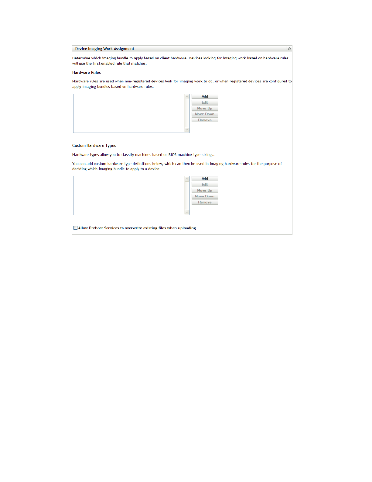
novdocx (en) 16 April 2010
4 Configure the following:
“Hardware Rules” on page 80
“Custom Hardware Types” on page 86
“Allow Overwrites” on page 90
5 Click either Apply or OK to save the changes.
This sets the default imaging work assignments for devices registered in the Management Zone.
Hardware Rules
You can specify hardware-based rules for a Imaging bundle. This enables any device matching those
rules to have the specified bundle applied to it when it boots.
For example, you can create a rule that applies a bundle to any device with at least 512 MB of RAM
and 150 GB of hard drive space.
A work rule is made up of filters that are used to determine whether a device complies with the rule.
The rules use logic to determine whether a device meets the requirements for applying the Imaging
bundle. The AND, OR, and NOT logical operators are used for creating filtering for the rule.
When a device is seeking work to be done, it scans the rules until it finds a rule where all of the
rule’s filters match the device, then executes the bundle assigned to the rule.
The following table lists the tasks you can perform to configure hardware rules:
80 ZENworks 10 Configuration Management Preboot Services and Imaging Reference

Table 2-7 Hardware Rules Tasks
Task Steps Additional Details
novdocx (en) 16 April 2010
Add a hardware rule 1. Click Add next to the Hardware
Rules list box, which opens the
Rule Construction dialog box.
2. To create the hardware rule, follow
the instructions contained in “Rule
Construction Dialog Box” on
page 82.
3. After exiting the Rule Construction
dialog box, click Apply at the
bottom of the configuration page to
save the new rule.
Edit a hardware rule 1. Select a hardware rule, then click
Edit, which opens the Rule
Construction dialog box in edit
mode.
2. To edit the hardware rule, follow
the instructions contained in “Rule
Construction Dialog Box” on
page 82.
3. After exiting the Rule Construction
dialog box, click Apply at the
bottom of the configuration page to
save the rule’s changes.
The information that you configure in the
Rule Construction dialog box comprises
one rule. You can add multiple rules.
Each time you click Add to use the Rule
Construction dialog box, you can select
the same bundle as the previous time
that you used the dialog box, or you can
select a different bundle for the rule.
Only the first hardware rule that is
matched is used when a device boots to
apply the assigned bundle.
Disable or enable a
hardware rule
Rearrange the order
of the hardware
rules
1. Select a hardware rule, then click
Edit.
2. In the Rule Construction dialog
box, select the check box for
Enabled to enable or disable it.
3. Click Apply at the bottom of the
configuration page to save the
rule’s change.
1. Select one hardware rule, then
click either Move Up or Move
Down.
You cannot move multiple rules at
one time.
2. Repeat as necessary to arrange
the order of the hardware rules.
3. Click Apply at the bottom of the
configuration page to save the new
rule order.
This is the only way to change the status
of a hardware rule.
Whether a hardware rule is enabled or
disabled is indicated in the Hardware
Rules list box. For example,
- Asset Tag Rule
The hardware rule order is important
because when the device boots, the first
rule that is found to match the device is
used to apply the bundle. The other
rules are ignored.
This means that only one bundle can be
applied to a booting device by virtue of a
hardware rule match.
Enabled
.
Setting Up Preboot Services and Imaging 81
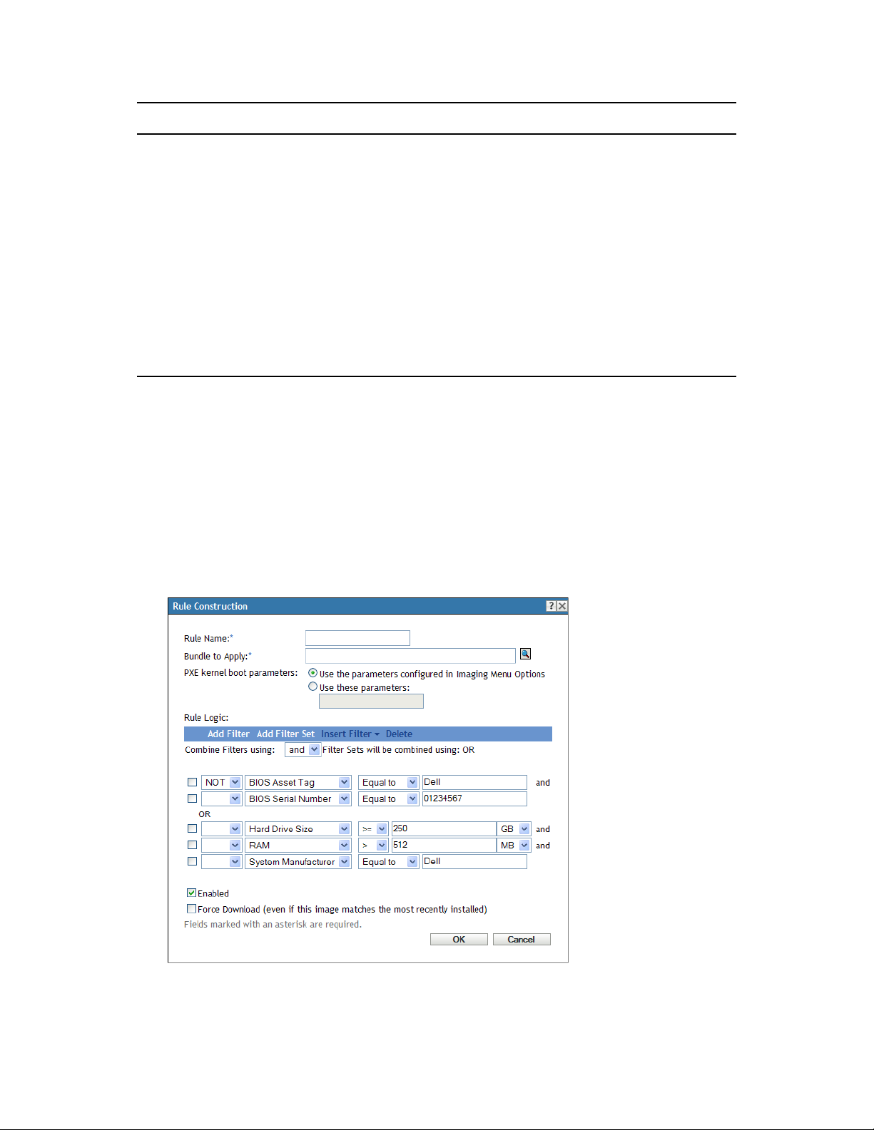
Task Steps Additional Details
novdocx (en) 16 April 2010
Remove hardware
rules
1. Select one or more hardware
rules, then click Remove.
2. Click Apply at the bottom of the
configuration page to cause
removal of the rules from the list.
You can use the Ctrl or Shift keys to
select multiple hardware rules to
remove them from the list.
If you remove a hardware rule, any work
you did to create it is lost. Removed
rules do not have any of their
information saved anywhere. Therefore,
if you only want to remove the rule
temporarily, take note of the rule’s
content before deleting it so that you
can more easily re-create it. For
example, either select it and click Edit
and note the data, or take a screen shot
of the dialog box.
Rule Construction Dialog Box
Understanding rule logic is important in using this dialog box. For more information, see “Rule
Logic” on page 84.
To configure a hardware rule:
1 If you plan to select Hardware Type when constructing a rule, you must first configure the
hardware type.
For instructions, see “Custom Hardware Types” on page 86.
2 Click Add in the Hardware Rules section to display the Rule Construction Dialog box:
3 In the Rules Construction dialog box, fill in the following fields and select or deselect the
options:
82 ZENworks 10 Configuration Management Preboot Services and Imaging Reference

Rule Name: This name is displayed in the rules listing on the Preboot Services page in the
Device Imaging Work Assignment section. Make it descriptive enough that you can later
remember its purpose.
Bundle to Apply: When a device is seeking work to be done, it scans the rules until it finds a
rule where all of the rule’s filters match the device, then executes the bundle assigned to the
rule. Each rule can be applied to only one bundle.
Because the rules, not the bundles, are listed in the Device Imaging Work Assignment section,
you can apply multiple rules to a given bundle. This means that a bundle has multiple chances
to be selected for device imaging work.
When multiple rules are listed, the first rule with criteria to match a device causes that rule’s
assigned bundle to be applied to the device.
If no rules match a device, then none of the applicable bundles are applied to the device.
PXE Kernel Boot Parameters: Select one of these two options:
Use the Parameters Configured in Imaging Menu Options: This causes the rule to use
the default boot parameters for the Management Zone.
Use These Parameters: Only the boot parameters that you specify here are used for this
rule.
Each parameter should be separated by a space.
novdocx (en) 16 April 2010
Enabled: This is the only way that you can temporarily disable a hardware rule. It is enabled
by default.
The rule’s status is shown by the first word in the work rules listing on the Preboot Services
page. For example,
Enabled - Asset Tag Rule
.
Force Download: Forces the download of the assigned bundle, even if it matches the most
recently installed bundle. By default, downloading the hardware rule is not forced.
By default, ZENworks imaging does not reimage a machine containing the same image. This
option allows you to force the image to be reapplied to the device. For example, you might
want to refresh all of your lab machines for the next use of the lab.
IMPORTANT: Use this option cautiously. It can create an endless loop, because the option
remains selected after an image has been applied. If you image a device that remains nonregistered after it is imaged, it is reimaged with the same image over and over each time it
boots. To prevent this, edit this hardware rule and deselect this option after you have imaged
the applicable devices.
4 Using the Rule Logic fields and options, create the hardware rule expression using the
following options:
Add Filter: Adds the new filter at the end of the list of filters.
Because the filter is added to the end of the last filter set, you cannot use this option to
select which filter set to add it to. Use the Insert Filter option to add a filter into an earlier
filter set.
Add Filter Set: Adds a new set of filters, beginning with one filter in the set. The filter set
order cannot be rearranged.
Insert Filter: Allows you to insert a new filter either above or below the selected filter.
This also enables to you specify which filter set to add a filter to.
Delete: Removes the selected filters from the rule.
Setting Up Preboot Services and Imaging 83

Combine Filters Using: The default is to have filters ANDed and filter sets ORed. You
can use this field to reverse these Boolean functions for the filters and sets.
Using OR for filter sets means that all filters in a set must be matched to apply the rule, but
any of the sets can be matched to apply the rule.
Using AND for the filter sets means the reverse. At least one filter in each set must be
matched for the rule to be applied.
An expression consists of a criteria option, operator, and value, and in some cases, a qualifier.
For example:
RAM (in MB) =< 512 MB
RAM (in MB)
is the criteria option, =< is the operator,
512
is the value, and MB is the qualifier.
If necessary, you can use NOT (in the first blank field with a down-arrow) to perform a logical
negation of the expression. For example:
NOT RAM (in MB) =< 512 MB
In the above example, the rule is applied only to devices with less than 512 MB of RAM.
You can use more than one expression for the rule. For example:
RAM (in MB) =< 512 MB or
Hard Drive Size (in MB) < 20 GB
Hardware Type displays in the criteria options list only if you have previously configured a
custom hardware type and saved it by clicking Apply at the bottom of the Preboot Services
configuration page.
novdocx (en) 16 April 2010
IMPORTANT: Be aware of the possibility of creating conflicting filters or rules. For example,
if you specify a RAM condition in multiple filters, make sure the effective logical operators
where each is configured make sense for the megabyte values that you enter. In other words, if
two filters are both required (ANDed), you would not want one filter to require exactly 512 MB
of RAM and the other to specify at least 512 MB of RAM.
5 Click OK to exit the dialog box and place the new hardware rule into the Hardware Rules list
box on the Preboot Services configuration page.
Rule Logic
A rule is made up of one or more filters that are used to determine whether a device complies with
the rule. The Rule Construction dialog box begins with one empty filter. A device must match the
entire filter list of a rule (as determined by the logical OR nd AND operators that are explained
below) for the rule to apply to the device.
A filter is a row of fields providing a condition that must be met by a device in order for the bundle
to be applied. For example, you can add a filter to specify that the device must have exactly 512 MB
of RAM in order to be accepted by the rule, and you can add another filter to specify that the hard
drive be at least 20 GB in size. There is no technical limit to the number of filters that you can add in
the rule, but there are practical limits, such as:
Designing a rule that is easy to understand
Devising the rule so that you do not accidentally create conflicting filters
Being able to view the dialog box as it grows in size because of the filters and filter sets that
you add
84 ZENworks 10 Configuration Management Preboot Services and Imaging Reference

Filters can be added individually or in sets. Each set contains logical operators within the set and
logical operators determine the association between the sets.
By default, the logical operator AND is displayed for the filters within a set in the Combine Filters
Using field (which you can change), and OR is displayed in the Filter Sets Will Be Combined Using
field (display-only). If you change the Combine Filters Using field to OR, the Filter Sets Will Be
Combined Using field then displays AND.
You can think of filters and filter sets as using algebraic notation parentheticals, where filters are
contained within parentheses, and sets are separated into a series of parenthetical groups. Logical
operators (AND and OR) separate the filters within the parentheses, and the operators are used to
separate the parentheticals.
For example, “(u AND v AND w) OR (x AND y AND z)” means “match either uvw or xyz.” In the
Rule Construction dialog box, it looks like this:
u AND
v AND
w
novdocx (en) 16 April 2010
OR
x AND
y AND
z
Filter sets cannot be nested. You can only enter them in series, and the first filter set to match the
device (the default of OR) is used to validate the rule so that the bundle can be applied to do imaging
work on the device.
The order in which filters and filter sets are listed does not matter. For the OR operator, the first to be
met satisfies the rule. For the AND operator, all items must be met to satisfy the rule.
TIP: You can easily run a test to see how these logical operators work. Access the Rule
Construction dialog box, click both the Add Filter and Add Filter Set options a few times each to
create a few filter sets, then switch between AND and OR in the Combine Filters Using field and
observe how the operators change. Then, either select the filters that you added and click Delete, or
click Cancel to exit the Rule Construction dialog box.
You can set up the conditions for a rule by adding all of the filters and filter sets that you need to
identify the type of device you want to match. You typically do not need to set up complex rules.
However, because you can apply multiple rules to a bundle, you can further complicate the use of
logical operators, because each rule is considered to be an OR condition for the bundle, causing the
bundle to be applied if any one of the rules matches the device.
For example, you could create several rules for the bundle with each rule being a long listing of
AND conditions to be met. This means that each rule becomes a specific set of criteria for a device
to meet, causing the bundle to be applied if one is met. Conversely, if you add that same amount of
information into one rule (using filter sets for the AND and OR conditions), it might make the dialog
box so long that it becomes unmanageable.
Setting Up Preboot Services and Imaging 85

To determine what you need, consider the following possibilities:
One filter set with multiple filters
Multiple filter sets with only one or a few filters per set
Multiple filter sets each with multiple filters
Multiple rules per bundle
Remember that the logical operators for filters within a set are the opposite of the operators between
the sets, and all rules for a bundle use the OR condition. For example, suppose you are selecting the
operator in the Combine Filters Using field:
Table 2-8 OR and AND Operator Explanations
Operator Within Filter Sets Between Filter Sets Multiple Rules Per Bundle
novdocx (en) 16 April 2010
OR Only one filter in the set needs
to apply to the device (OR
condition). The first filter that
applies is used.
AND All filters within the set must
apply to the device (AND
condition).
Each filter set must have one
filter in it that applies to the
device (AND condition).
Only one filter in the set must
apply to the device (OR
condition). The first filter that
applies is used.
The first rule that applies
is used (OR condition).
The first rule that applies
is used (OR condition).
Obviously, adding filter sets complicates the use of logical operators, and adding multiple rules to
the bundle further complicates it. Therefore, carefully plan how to configure your information
before using the Rules Configuration dialog box.
Custom Hardware Types
Custom hardware types enable you to include any devices matching your custom type to have the
bundle assigned to the hardware rule applied to them when the devices boot. For example, you can
create a rule that applies the bundle to any device that is a laptop by entering the applicable string as
a custom hardware type, selecting Hardware Type in the Rule Construction dialog box, then
selecting your custom type.
The Hardware Type option does not display in the Rule Construction dialog box until at least one
custom type has been configured.
The following table lists the tasks you can perform to configure custom hardware types:
86 ZENworks 10 Configuration Management Preboot Services and Imaging Reference

Table 2-9 Custom Hardware Type Tasks
Task Steps Additional Details
novdocx (en) 16 April 2010
Add a custom
hardware type
Edit a custom
hardware type
1. Click Add next to the Custom
Hardware Types list box, which
opens the Custom Hardware Type
dialog box.
2. To create the custom hardware
type, follow the instructions
contained in “Custom Hardware
Type Dialog Box” on page 88.
3. After exiting the Custom Hardware
Type dialog box, click Apply at the
bottom of the configuration page to
save the new custom type.
1. Select a custom hardware type,
then click Edit, which opens the
Custom Hardware Type dialog box
in edit mode.
2. To edit the custom hardware type,
follow the instructions contained in
“Custom Hardware Type Dialog
Box” on page 88.
3. After exiting the Custom Hardware
Type dialog box, click Apply at the
bottom of the configuration page to
save the custom type’s changes.
In the Custom Hardware Type dialog
box you can add multiple strings, which
identify specific hardware type
information in the device’s BIOS.
The set of strings that you add in the
dialog box is considered one custom
hardware type that is identified by the
name you also provide in the dialog box.
The custom type won’t display in the
drop-down list of hardware items on the
Rule Construction dialog box until you
click Apply or OK to save the
configuration.
Rearrange the order
of the custom
hardware types
1. Select one custom hardware type,
then click either Move Up or Move
Down.
You cannot move multiple types at
one time.
2. Repeat as necessary to arrange
the order of the custom hardware
types.
3. Click Apply at the bottom of the
configuration page to save the new
custom type’s order.
The custom hardware type order is
important because when the device
boots, the first type that is found to
match the device is used to apply the
assigned bundle. The other types are
ignored.
Setting Up Preboot Services and Imaging 87
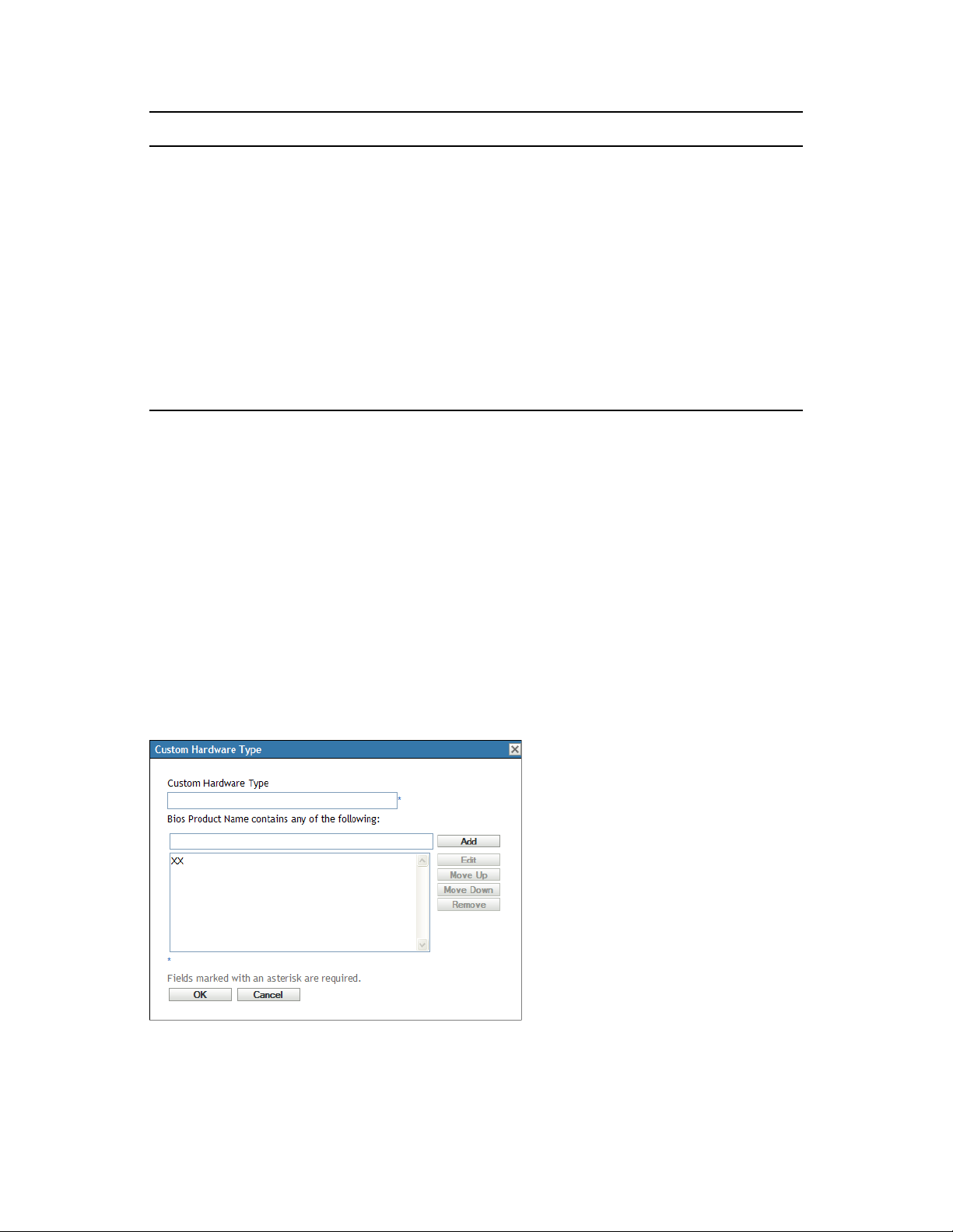
Task Steps Additional Details
novdocx (en) 16 April 2010
Remove custom
hardware types
1. Select one or more custom
hardware types, then click
Remove.
2. Click OK to exit the dialog box and
save the deletions.
3. Click Apply at the bottom of the
configuration page to remove the
custom types from the list.
You can use the Ctrl or Shift keys to
select multiple custom hardware types
to remove them from the list.
By removing a custom hardware type,
any work you did to create it is lost.
Removed types do not have any of their
information saved anywhere. Therefore,
if you only want to remove the rule
temporarily, take note of the type’s
content before deleting it so that you
can more easily re-create it. For
example, either select it and click Edit
and note the data, or take a screen shot
of the dialog box.
Custom Hardware Type Dialog Box
Custom hardware types enable you to include any devices matching your custom type and to have
the bundle assigned to the hardware rule applied to them when the devices boot. For example, you
can create a rule that applies the bundle to any device that is a laptop by entering the applicable
string as a custom hardware type, then select Hardware Type in the Rule Construction dialog box
and select your custom type.
The Hardware Type option does not display in the Rule Construction dialog box until at least one
custom type has been configured.
Your custom hardware type definitions are applicable only to rules; they do not otherwise apply to
the Management Zone.
Following is the Custom Hardware Type dialog box:
Figure 2-4 Custom Hardware Type dialog box
To configure custom hardware types, perform the tasks in the following table:
88 ZENworks 10 Configuration Management Preboot Services and Imaging Reference

Table 2-10 Custom Hardware Type Tasks
Task Steps Additional Details
novdocx (en) 16 April 2010
Configure a custom
hardware type
Edit a custom
hardware type
1. Specify a name for the custom
type in the Hardware Type Name
field.
2. Specify a string in the BIOS Strings
field, then click Add to add it to the
list box.
3. Repeat Step 2 for each BIOS
string to be added to this custom
type.
4. Click OK to exit the dialog box.
5. Click Apply (located at the bottom
of the Preboot Services
configuration page) to save your
new custom type.
1. In the Custom Hardware Type
dialog box, to edit the custom
hardware type’s name, edit the
name in the Hardware Type Name
field.
2. To edit a string in the list, select it,
then click Edit.
3. In the Edit String dialog box, edit
the string, then click OK.
4. Click OK to exit the dialog box.
5. Click Apply (located at the bottom
of the Preboot Services
configuration page) to save your
custom type changes.
The new custom type does not display
in the Rule Construction dialog box until
you have clicked Apply to save it.
The strings you can enter are anything
that you want to match in the device’s
BIOS.
To determine the BIOS product names
of your servers or laptops, use the
img -i
maintenance mode prompt, which
displays various BIOS information. The
BIOS information that you need is listed
in the Product Name field. For servers
and laptops, you can enter partial
strings to select all BIOS product names
containing that string.
command at the imaging
Rearrange the order
of the strings in the
list
1. In the Custom Hardware Type
dialog box, select one string, then
click either Move Up or Move
Down.
2. Repeat as necessary to arrange
the order of the strings.
3. Click OK to exit the dialog box.
4. Click Apply (located at the bottom
of the Preboot Services
configuration page) to save your
custom type changes.
You cannot move multiple strings at a
time.
Setting Up Preboot Services and Imaging 89

Task Steps Additional Details
novdocx (en) 16 April 2010
Remove strings
from the list
1. In the Custom Hardware Type
dialog box, select one or more
strings, then click Remove.
2. Click OK to exit the dialog box.
3. Click Apply (located at the bottom
of the Preboot Services
configuration page) to save your
custom type changes.
You can use the Ctrl or Shift keys to
select multiple strings to remove them
from the list.
Allow Overwrites
Select the Allow Preboot Services to Overwrite Existing Files when Uploading check box if you
.zmg
want existing
files to be overwritten by a newer version when the image is taken.
2.5.4 Configuring the Server Referral List
Referral lists are used to make sure managed devices belonging to other Management Zones can
access their home zone. For more information, see Section 1.3.5, “Server Referral List,” on page 25.
1 In ZENworks Control Center, click Configuration in the left pane to display the Configuration
tab, then if it’s not expanded, click Management Zone Settings.
2 Click Device Management to expand its listing, then select Preboot Services to display the
configuration sections.
3 Locate and expand the Server Referral List section:
Figure 2-5 Server Referral List panel
4 To configure a server referral list, complete the tasks in the following sections, as applicable:
“Configuring Imaging Servers in the Server Referral List” on page 90
“Configuring ZENworks Mixed Environment Imaging Servers” on page 91
Configuring Imaging Servers in the Server Referral List
To configure the List of Server IP Addresses and DNS Names list box, perform the tasks in the
following table:
90 ZENworks 10 Configuration Management Preboot Services and Imaging Reference

Table 2-11 Server Referral List Configuration Tasks
Task Steps Additional Details
novdocx (en) 16 April 2010
Add a server to the
server referral list
Edit a listed server 1. Select a server in the list, then click
Rearrange the order
of the servers in the
server referral list
Remove servers
from the server
referral list
1. In the List of Server IP Addresses
and DNS Names field, specify the
DNS name or IP address of a
server that can host preboot
operations, then click Add to place
it into the list.
2. Repeat as necessary to complete
the list of servers in your
environment capable of preboot
operations.
Edit.
2. In the Edit String dialog box, edit
the IP address or DNS name that
is displayed there, then click OK to
save the changes.
1. Select one server, then click either
Move Up or Move Down.
2. Repeat as necessary to arrange
the order of the servers.
1. Select one or more servers, then
click Remove.
You can add a range of IP addresses by
typing the beginning IP address, type a
space, a dash, another space, then type
the ending IP address of the range.
However, these are displayed as you
typed them when you click Add; the
addresses within the range do not
separate into individual IP addresses in
the list.
You cannot move multiple servers at
one time.
You can use the Ctrl or Shift keys to
select multiple servers to remove them
from the list.
Configuring ZENworks Mixed Environment Imaging Servers
After you have specified all of the necessary servers in the server referral list, you must place certain
tftp
files into the
directories of each ZENworks 7.x Imaging Server in the list in order for the
referrals to work with those traditional ZENworks Imaging Servers.
Do one of the following:
“Copy from ZENworks 10 Windows to ZENworks 7 NetWare or Windows” on page 91
“Copy from ZENworks 10 Windows to ZENworks 7 Linux” on page 92
“Copy from ZENworks 10 Linux to ZENworks 7 NetWare or Windows” on page 92
“Copy from ZENworks 10 Linux to ZENworks 7 Linux” on page 93
Copy from ZENworks 10 Windows to ZENworks 7 NetWare or Windows
From the ZENworks 10 Windows Imaging Server, copy the following files:
Location Files
%ZENWORKS_HOME%\share\tftp memdisk
nvlnbp.sys
pxelinux.0
Setting Up Preboot Services and Imaging 91

Location Files
%ZENWORKS_HOME%\share\tftp\referral\zfd70 pxemenu.txt
z_auto100.cfg
z_maint100.cfg
z_zpdis100.cfg
z_zpen100.cfg
To the following directory on the ZENworks 7 NetWare or Windows Imaging Server:
novdocx (en) 16 April 2010
NetWare:
Windows:
drive:\tftp
drive:\Program Files\ZEN Preboot Services\tftp\data
Do not replicate any directory structure from the ZENworks 10 server. Just copy the files to the
tftp
directory.
Copy from ZENworks 10 Windows to ZENworks 7 Linux
From the ZENworks 10 Windows Imaging Server, copy the following files:
Location Files
%ZENWORKS_HOME%\share\tftp memdisk
nvlnbp.sys
pxelinux.0
%ZENWORKS_HOME%\share\tftp\referral\zfd70 pxemenu.txt
z_auto100.cfg
z_maint100.cfg
z_zpdis100.cfg
z_zpen100.cfg
Copy the files to the following directory on the ZENworks 7 Linux Imaging Server:
/srv/tftp
Do not replicate any directory structure from the ZENworks 10 server. Just copy the files to the
tftp
directory.
Copy from ZENworks 10 Linux to ZENworks 7 NetWare or Windows
From the ZENworks 10 Linux Imaging Server, copy the following files:
92 ZENworks 10 Configuration Management Preboot Services and Imaging Reference

Location Files
/srv/tftp/ memdisk
nvlnbp.sys
pxelinux.0
/srv/tftp/referral/zfd70/ pxemenu.txt
z_auto100.cfg
z_maint100.cfg
z_zpdis100.cfg
z_zpen100.cfg
Copy the files to the following directory on the ZENworks 7 NetWare or Windows Imaging Server:
novdocx (en) 16 April 2010
NetWare:
Windows:
drive:\tftp
drive:\Program Files\ZEN Preboot Services\tftp\data
Do not replicate any directory structure from the ZENworks 10 server. Just copy the files to the
tftp
directory.
Copy from ZENworks 10 Linux to ZENworks 7 Linux
From the ZENworks 10 Linux Imaging Server, copy the following files:
Location Files
/srv/tftp/ memdisk
nvlnbp.sys
pxelinux.0
/srv/tftp/referral/zfd70/ pxemenu.txt
z_auto100.cfg
z_maint100.cfg
z_zpdis100.cfg
z_zpen100.cfg
Copy the files to the following directory on the ZENworks 7 Linux Imaging Server:
/srv/tftp
Do not replicate any directory structure from the ZENworks 10 server. Just copy the files to the
tftp
directory.
Setting Up Preboot Services and Imaging 93

2.5.5 Configuring Intel Active Management Technology (AMT)
The Intel AMT functionality allows you to accurately identify devices, even if they have had
physical drive replacements. This sets up Preboot Services with persistent device identification by
providing ZENworks with nonvolatile memory for storing the unique device identity.
For more information, see Section 1.3.6, “Intel Active Management Technology (AMT),” on
page 26.
To set up global Intel AMT enterprise names:
1 In ZENworks Control Center, click Configuration in the left pane to display the Configuration
tab. If it’s not expanded, click Management Zone Settings.
2 Click Device Management to expand its listing, then select Preboot Services to display the
configuration sections.
3 Locate the Intel Active Management Technology (AMT) panel.
novdocx (en) 16 April 2010
4 Fill in the fields:
Name List: This list should contain at least one valid AMT enterprise name for every AMT
device in the Management Zone. Click Add to place each one into the list box.
Move Up/Move Down: Arranges the order in which the AMT names are listed. You can move
only one at a time.
Remove: To remove names from the list, select them, then click Remove.
5 Click either Apply or OK to save the changes
2.6 Overriding Preboot Services Defaults
You can determine which Novell Preboot Services Menu displays a configuration to use and
whether the menu should be displayed on a device when it boots. By default, the Management Zone
configuration applies to all folders and devices. You can override this at the folder or device level.
For more information on the Novell Preboot Services Menu options, see Section 1.3.2, “Novell
Preboot Services Menu,” on page 22.
The menu can be customized by editing the
Section 2.4.4, “Editing the Novell Preboot Services Menu,” on page 71.
pxemenu.txt
file. For more information, see
94 ZENworks 10 Configuration Management Preboot Services and Imaging Reference

To override the default configuration at the folder or device level:
1 In ZENworks Control Center, click the Devices in the left pane to display the Devices panel in
the Managed tab.
2 Select one of the following in the Name column:
The Details option next to the Servers or Workstations folder
The Servers folder, then a server contained in the folder
The Workstations folder, then a workstation contained in the folder
3 On the page that is displayed, click the Settings tab to display the Settings page options.
4 Click Preboot Services to display the Preboot Services configuration page:
novdocx (en) 16 April 2010
If you have not previously configured this folder or device, the following is displayed:
Current: (System) (Override settings)
and the Preboot Menu Options section is disabled for editing. The above text varies depending
on whether you are at the folder or device level.
5 To configure the settings for the folder or device, click Override.
The following is displayed:
Current: /Devices/Servers
Revert to settings from: (System)
and the Preboot Menu Options section is enabled for editing. The above text varies depending
on whether you are at the folder or device level.
6 Select which option to use:
Always Show Imaging Menu
Never Show Imaging Menu
Show Imaging Menu if CTRL+ALT is Pressed
PXE must be enabled on the device for the menu to be displayed.
7 Click Apply or OK.
OK: Enables the change and exits the page.
Setting Up Preboot Services and Imaging 95

Apply: Enables the change and retains focus on the page, so you can click Revert to
temporarily disable the configuration change.
8 To temporarily disable the change, click Revert and the Management Zone settings for the
menu remain in effect.
2.7 Enabling PXE on Devices
To image a device using Preboot Services, you need to find out if the device is PXE capable, and
then make sure that PXE is enabled.
PXE code is typically delivered with newer devices (PC 99 compliant or later) on the NIC.
This section includes the following information:
Section 2.7.1, “Enabling PXE on a PXE-Capable Device,” on page 96
Section 2.7.2, “Verifying That PXE Is Enabled on a Device,” on page 97
2.7.1 Enabling PXE on a PXE-Capable Device
novdocx (en) 16 April 2010
When PXE is enabled, it can lengthen the time of the boot process slightly, so most NICs have PXE
turned off by default. To enable PXE on a PXE-capable device:
1 Access the computer system BIOS and look at the Boot Sequence options.
The PXE activation method for a device varies from one manufacturer to another, but generally
one of the following methods is used:
Some BIOS have a separate entry in the BIOS configuration to enable or disable the PXE
functionality. In this case, set either the PXE boot setting or the Network boot setting to
Enabled.
Some BIOS extend the entry that allows you to configure boot order. For example, you
can specify that the system should try to boot from a diskette before trying to boot from
the hard drive. In this case, set the system to try Network boot before trying to boot from a
diskette or from the hard disk.
2 If PXE is not listed in the Boot Sequence options and if the NIC is embedded in the
motherboard, look at the Integrated Devices section of the BIOS, which might have an option
to enable PXE. PXE might be called by another name, such as MBA (Managed Boot Agent) or
Pre-Boot Service.
After enabling PXE in the Integrated Devices section, look at the Boot Sequence options and
move PXE so that it is first in the boot sequence.
3 Save any changes you have made and exit the system BIOS.
4 Reboot the device.
If the device does not have the network adapter and PXE integrated into the motherboard, it uses the
installed NIC management software to prompt you to start PXE configuration during the boot
process.
For example, many network adapters that are PXE-aware prompt you to press Ctrl+S during the
boot process to allow you to configure the PXE functionality. Other network adapters might prompt
you to press Ctrl+Alt+B or another key combination to configure PXE.
96 ZENworks 10 Configuration Management Preboot Services and Imaging Reference

If the computer system does not have an integrated NIC, you might need to use NIC management
software to configure your NIC to support PXE. Refer to your NIC documentation for support of
PXE.
2.7.2 Verifying That PXE Is Enabled on a Device
After you have activated PXE, it becomes available in the Boot section of the BIOS. PXE is
correctly enabled on a device when the device attempts to establish a PXE session during the boot
process. You can see this happening when the device pauses during the boot process and displays the
following on the screen:
CLIENT MAC ADDR: 00 E0 29 47 59 64
DHCP...
The actual message displayed varies from one manufacturer to another, but you can identify it by the
obvious pause in the boot process as the device searches for DHCP.
2.8 Setting Up Devices for ZENworks Imaging
novdocx (en) 16 April 2010
The following sections cover procedures to prepare devices for imaging. The procedures that are
applicable to you depend on your imaging deployment strategy. For more information, see
Section 2.4.2, “Deploying Preboot Services in a Network Environment,” on page 60.
If you are using Preboot Services (PXE) as your imaging method, you need to enable PXE on the
device. For more information, see Section 2.3.1, “Using Preboot Services (PXE),” on page 47.
If you are using a ZENworks partition as your imaging method, you need to create the partition on
the device. For more information, see “Creating a ZENworks Partition” on page 56.
The following sections contain additional information:
Section 2.8.1, “Device Requirements,” on page 97
Section 2.8.2, “Enabling a Device for Imaging Operations,” on page 98
2.8.1 Device Requirements
This section gives the requirements for using a network-connected device.
It is possible (but usually not as convenient) to image a device without connecting to the network.
Such operations can’t be fully automated.
The following are the requirements for the device:
Table 2-12 Device Requirements
Device Must Have Because
A supported Ethernet
card
The device must connect with the Imaging Server to store or retrieve the
images. This connection is made when the device is under the control of the
ZENworks Imaging Engine. Therefore, make sure the device has a supported
Ethernet card. For more information, see Appendix H, “Supported Ethernet
Cards,” on page 255.
Setting Up Preboot Services and Imaging 97

Device Must Have Because
novdocx (en) 16 April 2010
Free disk space for a
ZENworks partition
(optional)
Standard hardware
architecture
PXE enabled If you are using Preboot Services, PXE must be enabled in the BIOS. For more
Supported imaging
partition type
Unless you are using PXE, unattended operations require a ZENworks partition
to be installed on the device hard disk, so that the ZENworks Imaging Engine
can gain control when booting. The default partition size is 150 MB, and the
minimum partition size is 50 MB. This partition is not required if you are
performing manual imaging operations using bootable CDs, DVDs, or diskettes.
Partition size can be in megabytes of disk space.
NEC* PC98 architecture is not supported.
information, see Section 2.3.1, “Using Preboot Services (PXE),” on page 47.
The supported partition types for imaging are the NTFS, FAT32, ReiserFS,
Ext2, and Ext3 file systems.
NOTE: ZENworks imaging does not support devices running boot managers, such as System
Commander. Boot managers create their own information in the MBR and overwrite the ZENworks
boot system, which prevents the device from communicating with the Imaging Server. If you are
using boot managers in your environment, you should disable or remove them before performing
imaging operations.
2.8.2 Enabling a Device for Imaging Operations
Use one of the following methods to enable a device for auto-imaging operations:
“Using PXE” on page 98
“Using a ZENworks Partition” on page 98
“Using a CD or DVD” on page 98
Using PXE
You can set up a device to be automatically imaged from Imaging bundles by enabling PXE on the
device.
For more information, see Section 2.7.1, “Enabling PXE on a PXE-Capable Device,” on page 96.
Using a ZENworks Partition
If you cannot enable PXE on the device, you can use a partition to perform unattended imaging
operations.
For more information, see “Creating a ZENworks Partition” on page 56.
Using a CD or DVD
If you cannot use the PXE or ZENworks partition methods to automate imaging of your devices,
you can manually image a device using an imaging CD or DVD.
For information, see Section 3.1.3, “Setting Up Disconnected Imaging Operations,” on page 117.
98 ZENworks 10 Configuration Management Preboot Services and Imaging Reference

3
Using Imaging
novdocx (en) 16 April 2010
3
This section provides instructions on how to use Preboot Services imaging operations in Novell®
ZENworks
Section 3.1, “Imaging Devices,” on page 99
Section 3.2, “Multicasting Images for ZENworks Imaging,” on page 122
Section 3.3, “Configuring Imaging Script Bundles for ZENworks Imaging,” on page 132
Section 3.4, “Assigning Imaging Bundles,” on page 134
Section 3.5, “Editing Imaging Work,” on page 138
®
10 Configuration Management:
3.1 Imaging Devices
Preboot Services provides tools for creating and compressing images of device hard disks, as well as
images of specific add-on applications or sets of files. ZENworks also provides tools for
customizing such images and for making images available to auto-imaging operations.
You can take images of devices, then reimage them and other devices with those images. The
available devices are Windows servers and workstations.
ZENworks imaging supports devices that physically connect to the network that meet the minimum
requirements for devices. ZENworks imaging does not support imaging operations (creating or
restoring images) using wireless connectivity. Devices with logical volumes (LVMs) are not
supported for imaging.
NOTE: ZENworks imaging does not support devices running boot managers, such as System
Commander. Boot managers create their own information in the MBR and overwrite the ZENworks
boot system, which prevents the device from communicating with the Imaging Server. If you are
using boot managers in your environment, you should disable or remove them before performing
imaging operations.
Some imaging tasks can be performed manually on a device, some in ZENworks Control Center,
and some in both:
Section 3.1.1, “Using ZENworks Control Center for Imaging,” on page 99
Section 3.1.2, “Using the Command Line for ZENworks Imaging,” on page 107
Section 3.1.3, “Setting Up Disconnected Imaging Operations,” on page 117
3.1.1 Using ZENworks Control Center for Imaging
The following imaging tasks are available in ZENworks Control Center:
“Taking a Base Image of a Device” on page 100
“Creating an Add-On Image for an Existing Bundle” on page 102
“Configuring the ZENworks Image Bundle for Automatic Imaging” on page 103
Using Imaging
99

“Creating and Configuring the Third-Party Image Bundle for Automatic Imaging” on page 105
“Using a Script to Image a Device” on page 106
Taking a Base Image of a Device
A base image is an image of partitions and data on a source device’s hard disks. Normally, such an
image is prepared with the intent to completely replace the contents of a target device’s hard disks.
You can take an image of an existing device and use it to image a similar device, or use it as a
backup image for reimaging the original device. During the image restoration on a new device, if
you want the restored managed device to generate its own GUID and register as a new object in
ZENworks Control Center, you must run the following command on the managed device before
taking the image:
zac fsg -d
This command removes the workstation GUID in the file system in preparation for taking an image.
For more information about the zac command, see “zac(1)” in the ZENworks 10 Configuration
Management Command Line Utilities Reference.
novdocx (en) 16 April 2010
You must not run the
zac fsg -d
command if you want to take an image as a backup image of the
managed device. In this scenario, the restored managed device has the same GUID as the original
device.
To take an image of a device:
1 In ZENworks Control Center, click Devices in the left pane to display the Devices panel in the
Managed tab.
2 Click Servers or Workstations, then select the check box next to a device.
This selects the device for taking the image.
3 Click Action > Take image.
You can also select the check box next to Servers or Workstations to start this wizard, then click
Action > Take i m a ge. If you do so, you are asked to select a device from the group. Then the
File Information page is displayed.
4 Click Next to display the File Information page:
5 Fill in the fields:
Image Format: Select the format of the image to be taken for the device.
Server and File Path: Click the icon to display the Server and Path Information dialog box.
Configure the following options.
Server Object, IP, or DNS: Click the icon to browse for and select the object of the
Primary Server or the device that is promoted to the Imaging Server role. You can also
specify the IP address or the DNS name of the Primary Server or of the device that is
promoted to the Imaging Server role.
Ensure that the DNS server is up and running, and the DNS name is successfully resolved
before configuring this option.
Directory Path on Server: Click the icon to browse for and select the
repo\images
100 ZENworks 10 Configuration Management Preboot Services and Imaging Reference
directory.
\content-
 Loading...