

Page 1

Novell exteNd Composer
5250 Connect
™
5.0
www.novell.com
USER’S GUIDE
Page 2

Legal Notices
Copyright © 2000, 2001, 2002, 2003, 2004 SilverStream Software, LLC. All rights reserved.
Title to the Software and its docum entatio n, and pa tent s, copy rights and a ll other prop erty rig hts applicable theret o,
shall at all times remain solely and exclusiv ely with Silve rStrea m and its licensors, a nd you shall n ot take any actio n
inconsistent with such title. The Software is protected b y co py right l aws an d i nte rnat ion a l trea ty pro visi ons . You
shall not remove an y copyri ght no tices or oth er prop rietar y notices from the Sof tware or its docum entati on, and y ou
must reproduce such notices on all copies or extracts of the Software or its documentation. You do not acquire any
rights of owne r ship in the Software.
Novell, Inc.
1800 South Novell Place
Provo, UT 85606
www.novell.com
exteNd Composer 5250 Connect User’s Guide
January 2004
Page 3

Online Documentation: To access the online documentation for this an d o ther Novell products , and to
get updates, see www.novell.com/documentation.
Novell Trademarks
eDirectory is a trademark of Novell, Inc.
exteNd is a trademark of Novell, Inc.
exteNd Composer is a trademark of Novell, Inc.
exteNd Director is a trademark of Novell, Inc.
jBroker is a trademark of No vell, Inc.
NetWare is a registered trademark of Novell, Inc.
Novell is a registered trademark of Novell, Inc.
SilverStream Trademarks
SilverStream is a registered trademark of SilverStream Software, LLC.
Third-Party Trademarks
All third-party trademark s ar e the p rop e rty of the ir respective owners.
Third-Party Software Legal Notic es
Jakarta-Regexp Copyright ©1999 The Apache Software Foundation. All rights reserved. Xalan Copyright ©1999
The Apache Software Foundation. All rights reserved. Xerces Copyright ©1999-2000 The Apache Software
Foundation. All rights reserved. Jakarta-Regexp , Xalan and Xerces software is licensed by The Apache Software
Foundation a nd r e distribution and use of Ja ka rt a -R e ge xp , Xalan and Xe r ces in source and b ina r y f orm s , with or
without modification, are permit ted provided that the following condit ions are met: 1. Redistributions of sour ce code
must retain the above copy righ t n otic es, this list of conditions and the fo llowi ng di sclaim e r. 2. Redistributions in
binary form must reprod uce th e ab ov e cop yrigh t n otice , t his l ist o f c on dit ions a nd th e foll owin g disc laim e r in the
documentation a nd /o r other materials pr o v ide d w ith the distribution. 3. The end-user do c um e nta tio n inc lu de d w ith
the redistribution, if any, must include the following acknowledgment: "This product includes software developed
by the Apache Software Foundation (http://www.apache.org/)." Alternately, this acknowledgment may appear in the
software itself, if and wherever such third-party acknowledgments normally appear. 4. The names "The Jakarta
Project", "Jakarta-Regexp", "Xerces", "Xalan" and "Apache Software Foundation" must not be used to endorse or
promote products derived from this software without prior writte n permission. For written permission, please contact
apache@apache.org. 5. Products derived from this software may not be called "Apache" nor may "Apache" appear
in their name, without prior writt en p ermissio n of The Apache Software Foundation. THIS SOFTWARE IS
PROVIDED "AS IS" AND ANY EXPRESSED OR IMPLIED WARRANTIES, INCLUDING, BUT NOT
LIMITED TO, THE IMPLIED WARRANTIES OF MERCHANTABILITY AND FITNE SS FOR A P AR TICULAR
PURPOSE ARE DISCLAIMED. IN NO EVENT SHALL THE APACHE SOFTWA RE FOUNDATION OR ITS
CONTRIBUTORS BE LIABLE FOR ANY DIRECT, INDIRECT, INCIDENTAL, SPECIAL, EXEMPLARY, OR
CONSEQUENTIAL DAMAGES (INCLUDING, BUT NOT LIMITED TO, PROCUREMENT OF SUBSTITUTE
GOODS OR SER VICES ; LOS S OF USE, DAT A, OR PROFITS; OR BUSINESS INTER RUPTION) HOWEVER
CAUSED AND ON ANY THEORY OF LIABILIT Y, WHETHER IN CONTRACT, STRICT LIABILITY , OR
TOR T (INCLUDING NEGLIGENCE OR OTHERWISE) ARISING IN ANY W AY OUT OF THE USE OF THIS
SOFTWARE, EVEN IF ADVISED OF THE POSSIBILITY OF SUCH DAMAGE.
Copyright ©1996-2000 Autonomy, Inc.
Copyright ©2000 B rett McLaughlin & Jason Hunter . A ll rights reserve d. Redistribu tion and use in sou rce and binary
forms, with or without modifica tion, are permit ted provided tha t the following conditions are m et: 1. Redistribution s
of source code must re tain the above copyright no tic e, th is list of conditions, and th e following disclaimer. 2.
Redistributions in binary form mu st repro duce the above cop yright n otice, th is list of con ditions, a nd t he discla imer
that follows these conditions in the do cumentation and/o r other materials provided with the distribution. 3. Th e name
"JDOM" must not be used to endorse or promote products derived from this software without prior written
permission. For written permission, plea se con tact lice nse@jdo m.o r g . 4 . P rod ucts d e rived fro m this software m ay
Page 4

not be called "JDOM", nor may "JDOM" a ppe ar in their name, without prior writte n perm issio n from th e JDOM
Project Management (pm@jdom.org). THIS SOFTWARE IS PROVIDED "AS IS" AND ANY EXPRESSED OR
IMPLIED WARRANTIES, INCLUDING, BUT NOT LIMITED TO, THE IMPLIED WARRANTIES OF
MERCHANT ABILIT Y AND F ITNESS F OR A PARTICULAR PURPOSE ARE DIS CLAIMED. IN NO EVENT
SHALL THE APACHE SOFTWARE FOUNDATION OR ITS CONTRIBUTORS BE LIABLE FOR ANY
DIRECT, INDIRECT , INCIDENTAL, SPECIAL, EXEMPLARY, OR CONSEQUENTIAL DAMAGES
(INCLUDING, BUT NOT LIMITED TO, PROCUREMENT OF SUBSTITUTE GOODS OR SERVICES; LOSS
OF USE, DATA, OR PROFITS; OR BUSINESS INTERRUPTION) HOWEVER CAUSED AND ON ANY
THEORY OF LIABILITY, WHETHER IN CONTRACT, STRICT LIABILITY, OR TORT (INCLUDING
NEGLIGENCE OR OTHERWISE) ARISING IN ANY WAY OUT OF THE USE OF THIS SOFTWARE, EVEN IF
ADVISED OF THE POSSIBILITY OF SUCH DAMAGE.
This Software is der ived in part from the SSLav a™ Toolkit, which is Copyright ©19 96-19 98 by Phao s Technology
Corporation. All Rights Reserve d. Custo m er is pr ohibited from accessing the functio nality o f th e Ph aos software.
The code of this project is released under a BSD-like license [license.txt]: Copyright 2000-2002 (C) Intalio In c. Al l
Rights Reserve d. Redistribu tion and use of this soft ware and ass ociated docum entation ("Sof tware"), with or without
modification, are pe rm itted p r ovide d th at th e follo win g c ond itio ns are met: 1. Redistribution s of sou rce c o de m ust
retain copyright statements and notices. Redistributions must also contain a copy of this document. 2. Redistributions
in binary form must reprod uce the abov e copyright n otice, this li st of conditio ns, and the foll owing disclai mer in the
documentation and/or other materials provided with the distribution. 3. The name "ExoLab" must not be used to
endorse or promote products derived from this Software without pr ior writt en permission of Int alio Inc. F or written
permission, please contact info@exolab.org. 4. Products derived from this Software may not be called "Castor" nor
may "Castor" appe ar in their names without prior wri tten p e rm ission o f Intalio Inc. Exolab, Castor, and Intalio are
trademarks of Intalio Inc. 5. Due credit should be given to the ExoLab Project (http://www.exolab.org/). THIS
SOFTWARE IS PROVIDED BY INTALIO AND CONTRIBUTORS ``AS IS'' AND ANY EXPRE SSED OR
IMPLIED WARRANTIES, INCLUDING, BUT NOT LIMITED TO, THE IMPLIED WARRANTIES OF
MERCHANT ABILIT Y AND F ITNES S FOR A PARTICULAR PURPOSE, ARE DIS CLAIME D. IN NO EVE NT
SHALL INTALIO OR ITS CONTRIBUTORS BE LIABLE FOR ANY DIREC T, INDIRECT, INCIDENTAL,
SPECIAL, EXEMPLAR Y, OR CONSEQUENTIAL DAMAGES (INCLUDING, BUT NOT LIMITED TO,
PROCUREMENT OF SUBSTITUTE GOODS OR SERVICES; LOSS OF USE, DATA, OR PROFITS; OR
BUSINESS INTERRUP TION) HOWEVER CAUSED AND ON ANY THEORY OF LIABILITY, WHETHER IN
CONTRACT , STRICT LIABIL ITY, OR TORT (INCLUDING NEGLIGENCE OR OTHERWISE) ARISING IN
ANY WAY OUT OF THE USE OF THIS SOFTWARE, EVEN IF ADVISED OF THE POSSIBILITY OF SUCH
DAMAGE.
Page 5

Contents
About This Guide. . . . . . . . . . . . . . . . . . . . . . . . . . . . . . . . . . . . . . . . . . . . . . . . . . . . . . . . . . . . . . . . .7
1111 Welcome to exteNd Composer and 5250 User Interface 11
Before You Begin . . . . . . . . . . . . . . . . . . . . . . . . . . . . . . . . . . . . . . . . . . . . . . . . . . . . . . . . . . . .1 1
About exteNd Composer Connects. . . . . . . . . . . . . . . . . . . . . . . . . . . . . . . . . . . . . . . . . . . . . . .12
What is the 5250 (TDS) Connect? . . . . . . . . . . . . . . . . . . . . . . . . . . . . . . . . . . . . . . . . . . . . . . .14
About exteNd Composer’s 5250 Component . . . . . . . . . . . . . . . . . . . . . . . . . . . . . . . . . . . . . . .15
What Applications Can You Build Using the 5250 User Interface Component Editor?. . . . . . . .16
2222 Getting Started with the 5250 Component Editor 17
The Sample Transactions. . . . . . . . . . . . . . . . . . . . . . . . . . . . . . . . . . . . . . . . . . . . . . . . . . . . . .17
Creating a 5250 Connection Resource. . . . . . . . . . . . . . . . . . . . . . . . . . . . . . . . . . . . . . . . . . . .18
Creating a Style Sheet Resource . . . . . . . . . . . . . . . . . . . . . . . . . . . . . . . . . . . . . . . . . . . . . . . .23
XML Templates for Your Component . . . . . . . . . . . . . . . . . . . . . . . . . . . . . . . . . . . . . . . . . . . . .25
3333 Creating a 5250 Component 27
Before Creating a 5250 Component . . . . . . . . . . . . . . . . . . . . . . . . . . . . . . . . . . . . . . . . . . . . . .2 7
About the 5250 Component Editor Window . . . . . . . . . . . . . . . . . . . . . . . . . . . . . . . . . . . . . . . .31
About 5250-Specific Menu Bar Items . . . . . . . . . . . . . . . . . . . . . . . . . . . . . . . . . . . . . . . . . . . . .37
4444 Performing 5250 Actions 41
About Actions . . . . . . . . . . . . . . . . . . . . . . . . . . . . . . . . . . . . . . . . . . . . . . . . . . . . . . . . . . . . . . .41
About 5250-Specific Actions . . . . . . . . . . . . . . . . . . . . . . . . . . . . . . . . . . . . . . . . . . . . . . . . . . . .42
Recording a 5250 Session . . . . . . . . . . . . . . . . . . . . . . . . . . . . . . . . . . . . . . . . . . . . . . . . . . . . .45
Executing your 5250 Component . . . . . . . . . . . . . . . . . . . . . . . . . . . . . . . . . . . . . . . . . . . . . . . .56
Using the Animation Tools . . . . . . . . . . . . . . . . . . . . . . . . . . . . . . . . . . . . . . . . . . . . . . . . . . . . .58
Component with Connection Action . . . . . . . . . . . . . . . . . . . . . . . . . . . . . . . . . . . . . . . . . . . . . .63
Using Style Sheets in the Native Environment Pane . . . . . . . . . . . . . . . . . . . . . . . . . . . . . . . . .67
Using Other Actions in the 5250 Component Editor . . . . . . . . . . . . . . . . . . . . . . . . . . . . . . . . . .68
Handling Errors and Messages. . . . . . . . . . . . . . . . . . . . . . . . . . . . . . . . . . . . . . . . . . . . . . . . . .68
5555 Logon Components,Connections and Conne ction Pools 71
About 5250 Terminal Session Performance . . . . . . . . . . . . . . . . . . . . . . . . . . . . . . . . . . . . . . . .71
Connection Pool Architecture . . . . . . . . . . . . . . . . . . . . . . . . . . . . . . . . . . . . . . . . . . . . . . . . . . .72
How Do I Implement Pooling?. . . . . . . . . . . . . . . . . . . . . . . . . . . . . . . . . . . . . . . . . . . . . . . . . . .77
About the 5250 Logon Component . . . . . . . . . . . . . . . . . . . . . . . . . . . . . . . . . . . . . . . . . . . . . . .77
About the 5250 Logon Connection . . . . . . . . . . . . . . . . . . . . . . . . . . . . . . . . . . . . . . . . . . . . . . .84
Creating a Connection Pool . . . . . . . . . . . . . . . . . . . . . . . . . . . . . . . . . . . . . . . . . . . . . . . . . . . .87
Creating a Connection. . . . . . . . . . . . . . . . . . . . . . . . . . . . . . . . . . . . . . . . . . . . . . . . . . . . . . . . .87
Creating a Logon Component. . . . . . . . . . . . . . . . . . . . . . . . . . . . . . . . . . . . . . . . . . . . . . . . . . .88
Creating a Logon Connection Using a Pool Connection. . . . . . . . . . . . . . . . . . . . . . . . . . . . . . .90
Creating a Logon Connection using a Session Connection . . . . . . . . . . . . . . . . . . . . . . . . . . . .96
Creating a 5250 Terminal Component That Uses Pooled Connections . . . . . . . . . . . . . . . . . . .99
Errors Involving Logon Connections . . . . . . . . . . . . . . . . . . . . . . . . . . . . . . . . . . . . . . . . . . . . .100
Managing Pools. . . . . . . . . . . . . . . . . . . . . . . . . . . . . . . . . . . . . . . . . . . . . . . . . . . . . . . . . . . . .100
5555
Page 6

Connection Pool Management and Deployed Services. . . . . . . . . . . . . . . . . . . . . . . . . . . . . . 104
6666 Advanced Features 107
The 5250 Multi Row Wizard. . . . . . . . . . . . . . . . . . . . . . . . . . . . . . . . . . . . . . . . . . . . . . . . . . . 107
Handling System Messages . . . . . . . . . . . . . . . . . . . . . . . . . . . . . . . . . . . . . . . . . . . . . . . . . . 128
AAAA Java Code Pages 133
About Encodings . . . . . . . . . . . . . . . . . . . . . . . . . . . . . . . . . . . . . . . . . . . . . . . . . . . . . . . . . . . 133
BBBB 5250 Glossary 135
CCCC Testing 137
Environmental Differences between Animation Testing and Deployment Testing . . . . . . . . . 137
DDDD Reserved Words 139
6666
5250 Connect User’s Guide
Page 7

About This Guide
Purpose
The guide describes how to us e exteNd Composer 5250 Connect , referred to as the
5250 Component Editor. The 5250 Component Editor is a separately-installed
component editor in exteNd Composer.
Audience
The audience for the guide is developers and system integrato rs us ing ex teNd
Composer to create services and componen ts wh ich integr ate 52 50 ap plications .
Prerequisites
The guide assumes the reader is familiar with and has used exteNd Composer’s
development environment an d d e ploy ment o pti ons . You must also have an
understanding of th e 525 0 en vi ro nmen t.
Additional documentation
For the complete set of Novell exteNd Composer documentation, see the Novell
Documentation Web Site (http://www.novell.com/documentation-
index/index.jsp).
Organization
The guide is organized as follo ws:
Chapter 1, Welcome t o exteNd C ompo ser a nd 5250, gives a definition and
overview of the 5250 Comp onen t Edi t or.
Chapter 2, Getting Started with the 5250 Component Editor, describes the
necessary preparations for creating a 5 250 com pon ent.
7777
Page 8

Chapter 3, Creating a 5250 Compon ent , describes the parts of the component
editor.
Chapter 4, Performing 5250 Actions, describes how to us e the ba sic 5250 actions,
as well as the 5250 Multi Row Wizard.
Chapter 5, Logon Components, Connections and Connection Pools, describes
how to create logon components, connectio ns and conn ection p ools .
Chapter 6, Advanced Features, describes dealing with multi-row and multi-screen
data, and gives some tips on handling systems messages.
Appendix A,Java Code Pages, p rov ides refer ence inf ormatio n on char acter
encoding conversions.
Appendix B, is a gloss a ry.
Appendix C, Testing, describes environmental differences between animation
testing and depl oy ment t es t i ng.
Appendix D, Reserved Words, is a section of tho se words us ed only for the 5 250
Connect.
Conventions Used in the Guide
The guide uses the following typographical con ventions.
Bold typeface within instructions indicate action items, including:
Menu selections
Form selections
Dialog box items
Sans-serif bold typeface is used for:
Uniform Resource Identifiers
File names
Directories and partial pathnames
Italic typeface indicates:
Variable information that you supply
Technical terms used for the first time
Title of other Novell publications
Monospaced typeface indicates:
Method names
Code examples
8888 5250 Connect User’s Guide
Page 9

System input
Operating system objects
9999
Page 10

10
10 5250 Connect User’s Guide
1010
Page 11

1
Welcome to exteNd Composer and
5250 User Interface Chapter 1
Before You Begin
Welcome to the 5250 Connect Guide. This Guide is a companion to the exteNd
Composer User’s Guide, which details how to use all the features of Compos er,
except the Connect Component Editors. If yo u h aven’t looked at the Composer
User's Guide yet, please familiarize yourself with it before using this Guide.
exteNd Composer provides separate Componen t Editor s for each C onn ect, like
5250. The special features of each comp onen t editor are d escrib ed in sep arate
Guides like this one.
If you have been using exteNd Compos er, and are familiar with the core
component editor, the XML Map Component Editor , then this Guide should get
you started with the 5250 Component Editor.
Before you can begin work i ng wi th the 5250 Connect you mus t have installed it
into your existing exte Nd C omp os er. Likewise, before you can run any Servi ces
built with this Connect in the exteNd Composer Enterprise Server environment,
you must have already installed the server-side software for this Connect into
Composer Enterprise Se rver.
NOTE: T o be succes sful with this Component Editor , you mu st be familiar with the
IBM 5250 environmen t an d the applications th at y ou wan t to XML-enable.
Welcome to exteNd Composer and 5250 User Interface
11
Page 12
About exteNd Composer Connects
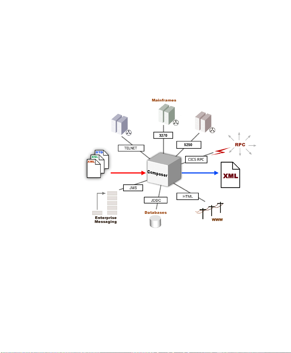
exteNd Composer is built upon a simple hub and spoke architecture (Fig.1-1). The
hub is a robust XML transformation engine that accepts req uests v ia XML
documents, performs transformation pro cesses on those documents and interfaces
with XML-enabled applications, and returns an XML r espons e do cumen t. Th e
spokes, or Connects, are plug-in modules that "XML- enable" sources of data that
are not XML-aware, bringing their data into the hub for pro cessi ng as XML.
These data sources can be anything fr om legacy COBOL/applications to Mess age
Queues to HTML pages.
12
Figure 1-1
5250 Connect User’s Guide
Page 13
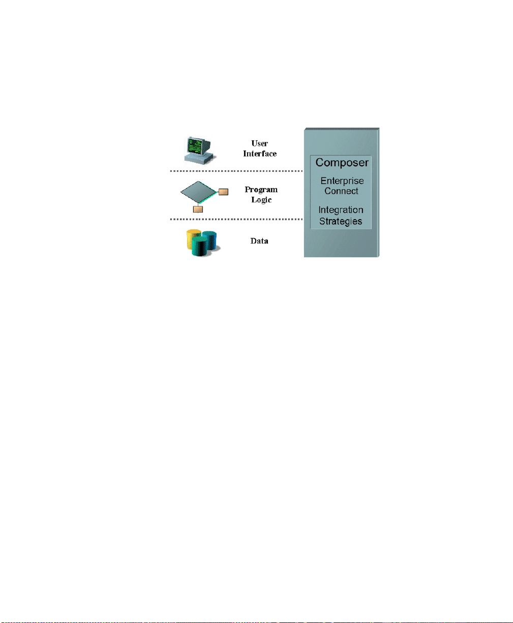
exteNd Composer Connects can be categorized by the integration str ategy each
one employs to XML-enable an information source. The integration strategies are
a reflection of the major divisions used in mod e rn systems des ign s f or I nternet-
based computing archit ectures . D ep endi ng on yo ur B2B needs and the
architecture of your legacy applications, exteNd Compo ser can integ rate yo ur
business systems at the User Interface, Program Logic, or Data levels.
Figure 1-2
Welcome to exteNd Composer and 5250 User Interface
13
Page 14
What is the 5250 (TDS) Conn ect?
The 5250 Connect XML-enables IBM AS/400-legacy system d ata using the User
Interface integration strategy by hooking into the Terminal Data Stream (TDS).
The term 5250 is commonl y us ed t o refer t o the generic "dumb terminal" types
used to connect to IBM AS/400 mid-range systems. When connecting to an IBM
AS/400, the 5250 TDS uses IB M’s EBCDIC character-encoding scheme. The
5250 TDS, which was d evel op ed i n t he 1 960 s, emerged as that generat ion’s
standard, and persists today. The 5250 TDS allows users to interact with legacy
applications through th e use of attention k eys (e.g., Enter and Fu nction Keys) th at
are interpreted by the application running on the host to perform the appropriate
actions. This interaction, through a dumb terminal, means that all the data is
processed information from the AS/400 computer. The 5250 terminal emulation
software can be used to make a m icrocomputer or PC act as if it were a 52 50-type
terminal while it is communicating with an AS/400.
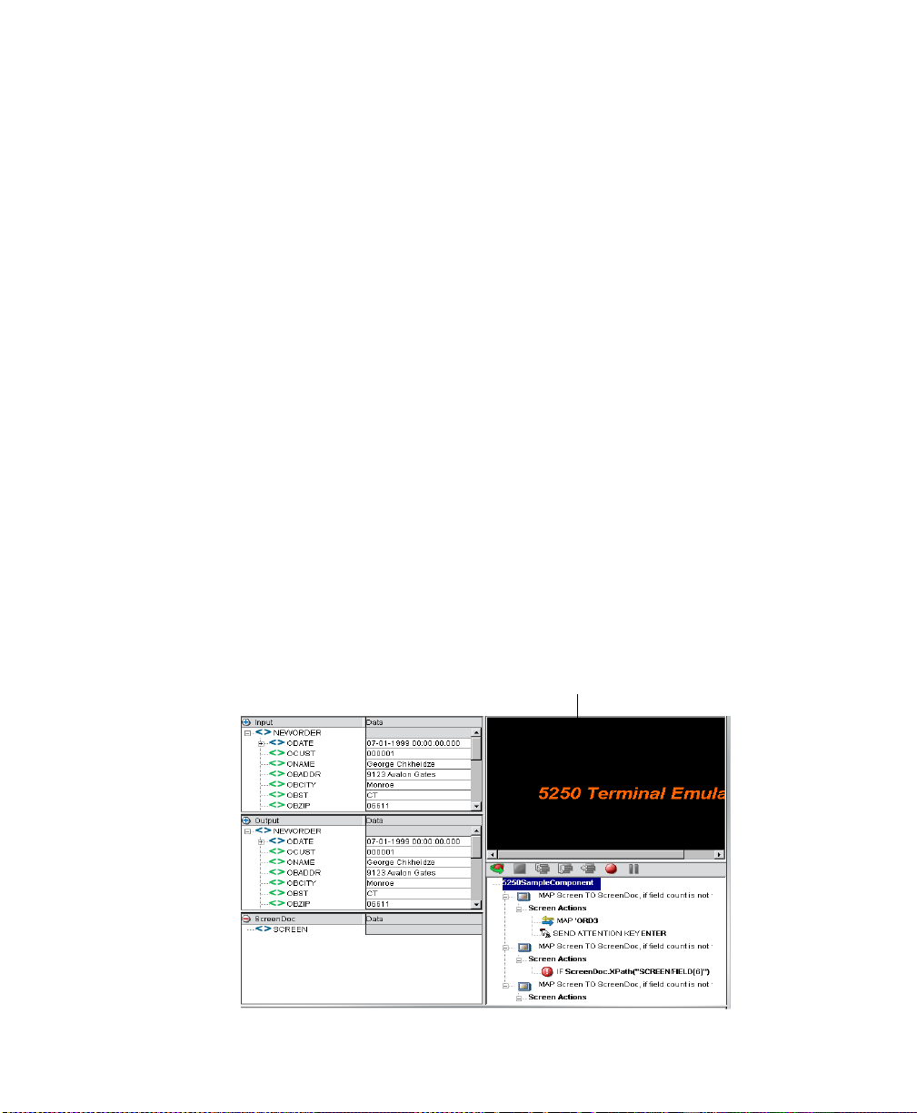
Using the 5250 Connect , you can make legacy applications running on an IBM
AS/400 and their business logic available to the internet, extranet, or intranet
processes. The 5250 Co nnect Component Editor al lows you to build W eb S ervices
by simply navigating through an application as if y ou were at a terminal session.
You will use XML request documents to drive the inquiries and updates into the
screens rather than keying, use the mes sages returned from applications screens to
make the same decisions as if you were at a termin al, and mov e the d ata and
responses into XML documents that can be r eturned to th e req uestor o r con t inue
to be processed. The 5250 screens app ear in th e Native En viron ment p ane o f the
5250 Component Editor.
14
5250 Screens appear in the Native Environment pane
5250 Connect User’s Guide
Page 15
About exteNd Composer’s 5250 Component
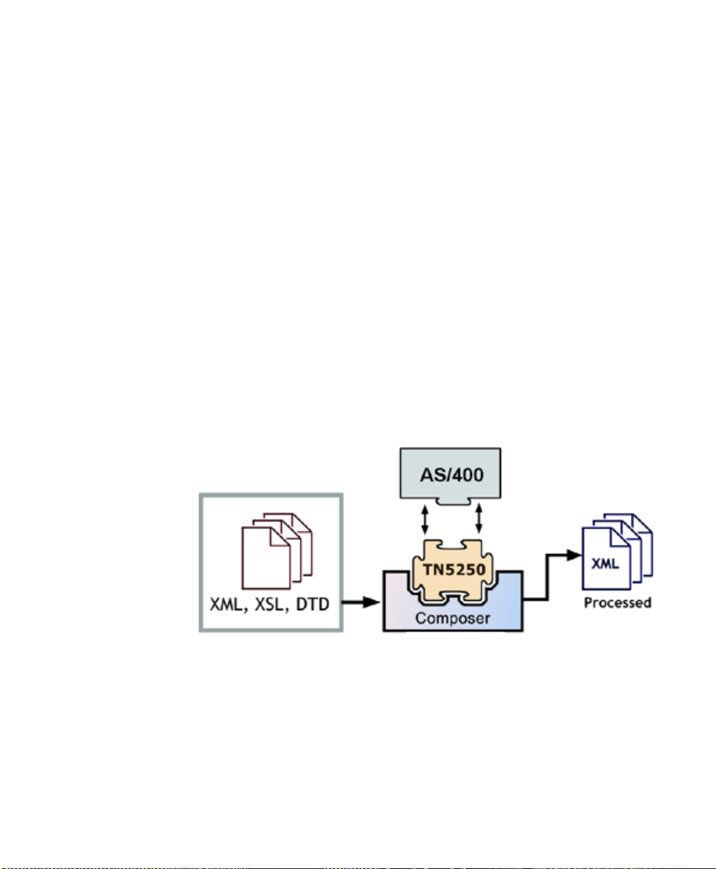
Much like the XML Map component, the 5250 comp onen t is desig ned to map,
transform, and transfer data between two different XML templates (i.e., request
and response XML documents). However, it is specialized to make a TN5250
connection to an AS/400 application, process the data us ing elements fro m a
DOM to a terminal session, and then map the results of the terminal session to an
output DOM. Y o u can then act upon the output DOM in any way that makes sen se
for your integration application. In es sen ce, yo u’re able to capture data from, or
push data to, a legacy system without ever having to alter the legacy system itself.
A 5250 component can perform simp le data mani pulati ons, such as mapping a nd
transferring data from an XML document into an AS/400 transaction, or perform
“screen scraping” of a 5250 transaction, putting the harvested data into an XML
document. It can also per form so phi s ti cate d operat i ons , such as mapp i ng and
manipulating screens that contain repeating rows and screens where more than
one screen of data is required to satisfy the requ est. These are termed multi-row
and multi-screen transactions within exteNd Composer . The 525 0 component has
all the functionality of the XML Map component and can process XSL, send mail,
and post and receive XML documents usin g the HTTP pro to col.
The following illustration shows how a 5250 component uses a TN5250
connection to interact with data on AS/400.
Figure 1-3
Welcome to exteNd Composer and 5250 User Interface
15
Page 16

What Applications Can You Build Using the 5250 User Interface Component Editor?
exteNd Composer, and consequently the 5250 Connect, can be applied to the the
following types of applications:
1 Business to Business Web Service interactions such as supply chain
applications.
2 Consumer to Business interactions such as self-service applications from
Web Browsers.
3 Enterprise Application Integrations where information from heterogeneous
systems is combined or chained together.
Fundamentally, the 5250 Component Editor allows you to extend any XML
integration you are building to include any of your business applications that
support 5250-based terminal interactions (See the exteNd Composer User's
Guide for more information.)
For example, you may have an application that retrieves a product's description,
picture, price, and inventory from regular ly updated databases and disp lays it in a
Web browser. By using the 5250 Component Editor , y ou can now get the current
product information from the operational systems and the static information (e.g.,
a picture) from a database and merge the information from these separate
information sources before di splayi ng it to a us er. This provides the same current
information to both your internal and external users.
16
5250 Connect User’s Guide
Page 17

2
Getting Started with the 5250
Component Editor Chapter 2
The Sample Transactions
For demonstration purposes, three tr ansactions are used throughout this d ocument
in the samples presented: P AR T , GORD, an d MENU. These transactions represent
typical transactions used by operators. The P AR T transaction represents a s cenario
in which an operator uses a SKU number to d rive an inq uiry to a d atabas e. The
GORD transaction represents a scenario in which an order for an item or several
items is placed. The MENU transaction represents a scenario in which an oper ator
navigates through a menu-driven application to get to a particular screen. The
PART, GORD, and MENU transactions are used to show you how t o bui ld
Composer services that do the same things as the real life scenarios.
Steps Commonly Used to Create a 5250 Component
While there are many ways to go about creating 525 0 co mpo nents, the most
commonly used steps in creating a sim ple compon ent are as follows:
1 Create XML Templates for transaction.
2 Create a Connection Resource.
3 Create a component.
4 Enter Record mode and navigate through the transaction using terminal
emulation available via the component editor’s Native Environment Pan e.
5 Drag and drop input document data into screen.
6 Process the transaction from the keyboard action.
7 Drag and drop screen results into output document.
8 Stop recording.
Getting Started with the 5250 Component Editor
17
Page 18
Creating a 5250 Connection Resource
Once you have the XML templates in place, your next step will be to create a
Connection Resource to access the AS/400 transaction. I f you try to create a 5250
Component in the absence of any available Connection Resources, a dialog will
appear, asking if yo u wish to create a Connection Res ource. By answering Yes to
this dialog, you will be taken to the appropriate wizard.
About Connection Resources
When you create a Connection Resource for the 5250 Component, you will have
two choices: a basic “TN5250 Connection” and a “5 250 Logo n Connecti on”. The
Logon Connection is us ed for connection pooling , whi ch wi ll b e explained in
greater detail in Chapter 5 of this Guide. For normal connections, you will use the
TN5250 Connection when you want to connect to any IBM AS/400 environment.
¾¾¾¾ T o cr ea te a 525 0 C o nnec tion Resource:
1 From the Composer File menu, select New > xObject, then open the
Resource tab and select Connection.
NOTE: Alternatively , und er Resource in the Composer window category
pane you can h igh lig ht Connection, click the right mous e bu tton , then select
New.
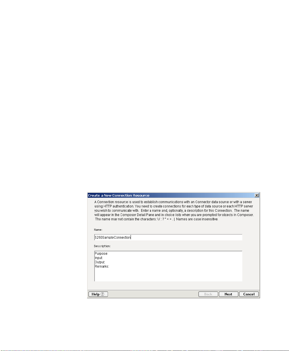
The Create a New Connection Resource Wizard appears.
18
2 Type a Name for the connection object.
3 Optionally, type Description text.
5250 Connect User’s Guide
Page 19
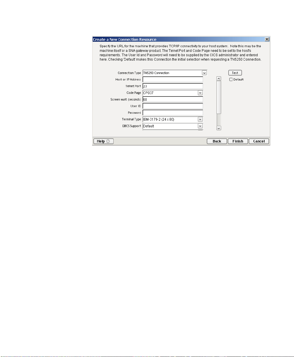
4 Click Next. The second page of the wizard appears.
5 Select the TN5250 Connection type from the pull-down menu. The dialog
changes appearance to show just the fields necessary for creating the 5250
connection.
6 In the Host or IP Address field, enter the physical address or alias for the
machine to which you are connecting. Your system administrator will
provide you with this information, which is defined in a separate host file.
7 In the Telnet Port field, enter the number of the port. The default port
number is 23.
8 In the Code Page field, specify a code page from the drop down list box
(See “About Code Page Support” on page -22).
9 The Screen wait ( seconds) field, di splays the am ount of time in seconds that
a 5250 T er minal component will wait for the arrival of the next screen in the
Map Screen Action pane.
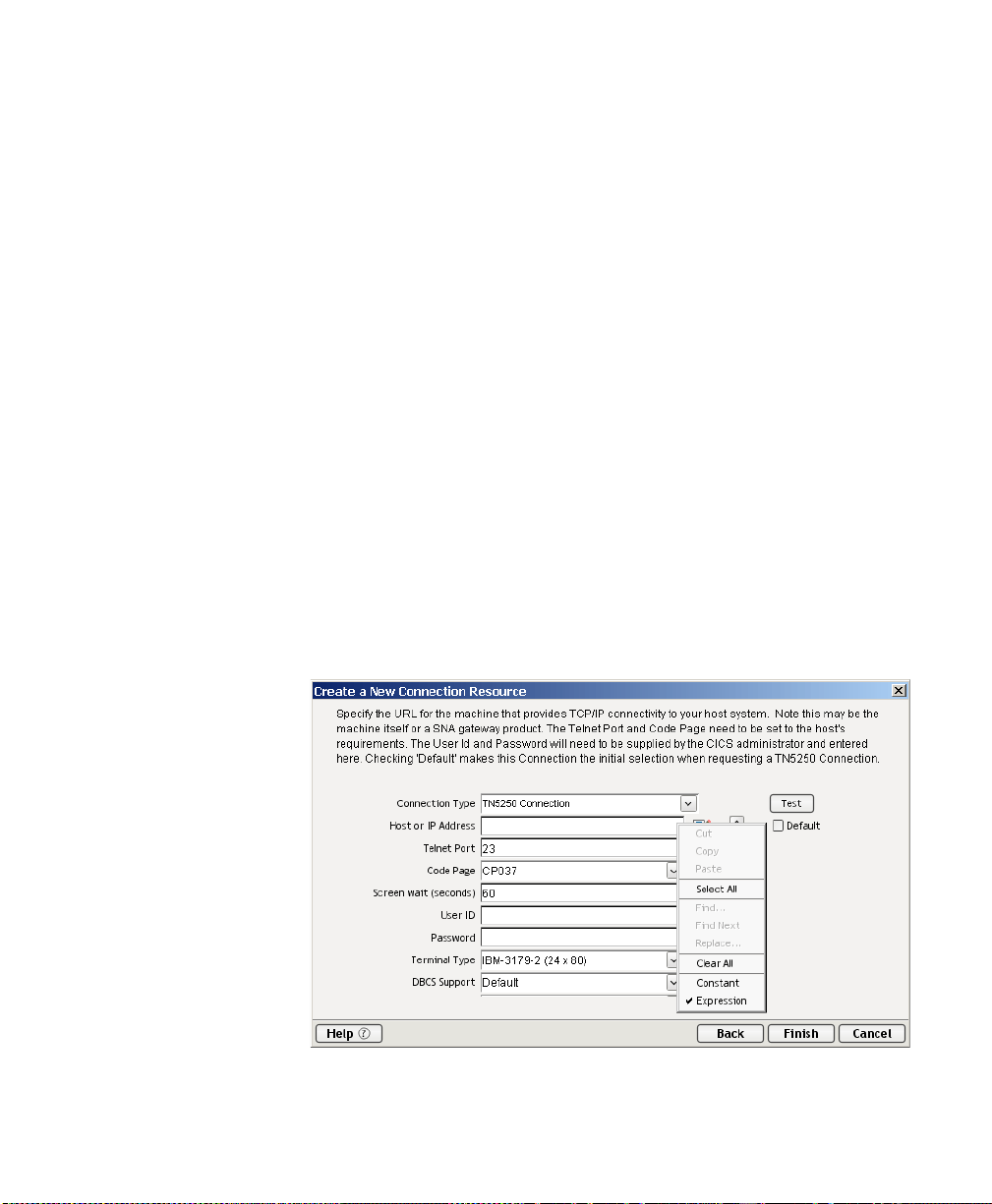
10 Enter a UserID and Password. Th ese are no t actuall y sub mitted to the host
during the establishment of a connection. They are simply defined here (the
password is encrypted). Right-mouse-click and choose Expression if you
want to make these fields expression-driven.
NOTE: After you’ve entered UserID and Password info in this dialog, the
ECMAScript global variables USERID and PASSWORD will point to these
values. You can then use these variables in expressions (or as described in
“5250 Specific Expression Builder Extensions” in Chapter 4.
Getting Started with the 5250 Component Editor
19
Page 20
11 The Terminal Type field lists the various types of terminals supported by
5250 components, including different screen sizes (i.e. 24x80 and 27x32).
Select from the drop down list box the type of terminal you are using.
12 In the DBSC Support field, select from the drop down list box your choice
of your Default, Double Encoding or SO/SI Using Ox1F.
13 In the DBCS Code Page field, select from the drop down list box the
appropriate code page.
14 Click the checkbox to enable Version 2.7 Compatability
15 Click in the Default checkbox if you’d like this particular 5250 connection
to become the default connection for subsequent 5250 components.
16 Click on the Advanced button for creating a Screen Handler, see Chapter 6,
“Handling System Messages ” for more detailed information.
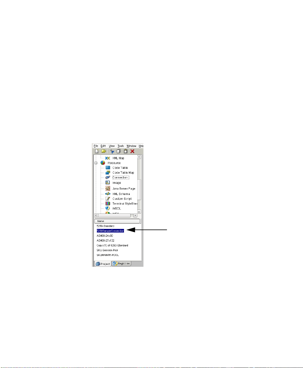
17 Click Finish. The newly created resource connection object appears in the
Composer Connection Resource detail pane.
20
Newly created
resource
5250 Connect User’s Guide
Page 21
About Constant and Expression Driven Connections
Y ou can s pecify Connection parameter values in on e of two ways: as Constants or
as Expressions. A consta nt-based parameter uses the static value you supply in the
Connection dialog every time the Connection is used. An expression-based
parameter allows you to set the value using a programmatic expression (that is, an
ECMAScript expression) , whi ch can result in a different va lue each time the
connection is used at runtime. This allows the Co nnection’s behavi or to be flexible
and vary based on runtime conditions.
For instance, one very simple use of an expression driven parameter in a TN5250
Connection would be to define the User ID and Password as PROJECT Variables
(e.g. PROJECT.XPATH(“USERCONFIG/MyDeployUser”). This way when you
deploy the project, you can up dat e t he PR OJEC T Variables in the Deplo ymen t
Wizard to val ues ap pro pri ate fo r t he fi nal d epl oy ment en viron ment . At th e ot her
extreme, you could have a custom script that queries a Java business object in the
Application Server to determine what User ID and Password to u se.
¾¾¾¾ T o s witch a parameter from Constant driven to Expression driv en:
1 Click the right mouse button in the parameter field you are interested in
changing.
2 Select Expression from the context menu and the editor button will appear
or become enabled.
3 Click on the Expression Editor button. The Expression Editor appears.
Getting Started with the 5250 Component Editor
21
Page 22
4 Create an expression (optionally using the pick lists in the upper portion of
the window) that evaluates to a valid parameter value at runtime.
5 Click OK.
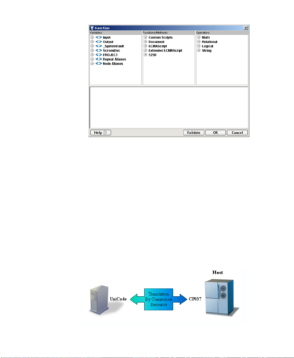
About Code Page Support
Code Page support i n ext eN d Com pos er Connection Resources all ow s y ou to
specify which Character Encoding scheme to use when translating characters sent
between exteNd Compos er and other host systems. exte Nd C omp os er dat a uses
Unicode character encoding (the Java and XML stand a rd). Exis ting legacy an d
other host systems use a variety of character encoding sche mes (i.e., Code Pages)
specific for their language or usage. A mechanism is needed to translate the
character encoding between these systems if they are to commu nicate with on e
another . This is handled in exteNd Comp oser by specifying the Code Page used by
a host system in the Connection Resource used to acces s that s ystem. For m ore
information on encoding, refer to “Java Co de P ages ” in Appendix A.
22
5250 Connect User’s Guide
Page 23
Creating a Style Sheet Resource
An additional resource associated with the 5250 Connect is the st yle sheet
resource. This allows you to create a style sheet with which to display the
emulation screen in the native environment pane.
¾¾¾¾ To create a Style Sheet Resource:
1 Select File>New> xObject from the Composer menu, then open the
Resource tab and select Terminal Style Sheet.
NOTE: Alternatively, you may highlight Terminal Style Sheet in the
Resource section of Composer’s category pane, cli ck your right mous e
button, and select New.
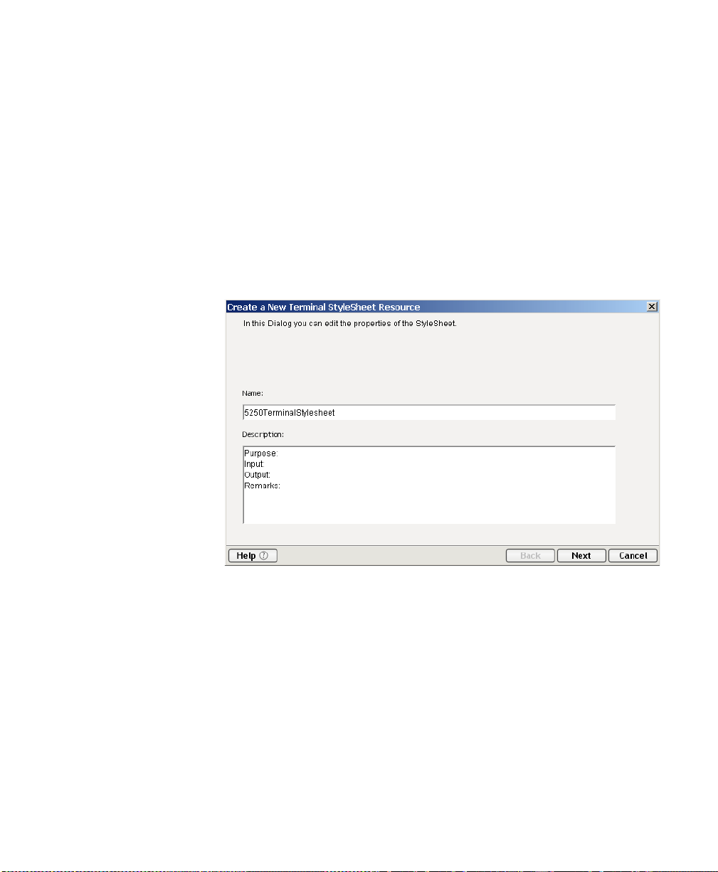
The Create a New Terminal Style Sheet wizard appears.
2 Type a Name for the new style sheet. Optionally, you may type in
Description text.
Getting Started with the 5250 Component Editor
23
Page 24
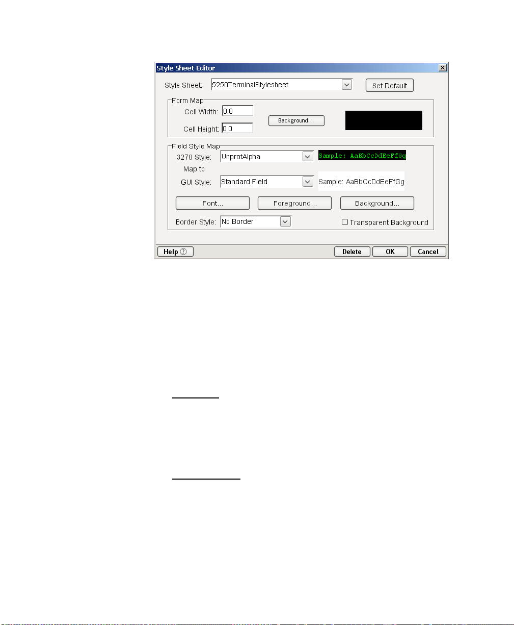
3 Click the Next button. The Style Sheet Editor window appears.
4 Use the Style Sheet Editor as described below to configure your style sheet:
Style Sheet - Select a st yle sheet fr om this d rop down list to chang e the
appearance of the emulation screen in the native environment pane. This
field initially contains the name you specified on the first page of the
T er minal S t yle Sheet wizar d. To create a new style sheet, type a name
over one of the names in the list.
24
Set Default - Select this button to make the currently selected style sheet
the default for a component.
Form Map:
Cell Widt h/H eig ht - Modify these settings for drawing characters
that may be truncated by changing font types.
Background - Select this button to see back gro und colo r op tions
for the style sheet.
Field Style Map:
3270 S tyl e - This con t rol lists the styles av ailable fro m the TDS.
You cannot edit these values. Select the style you wish to map to a
new style you create.
GUI Style - This control lists available styles you create. T ype over
an existing style to create a new one, then specify its Font,
Foreground, and Background using t he co rres pon ding buttons.
5250 Connect User’s Guide
Page 25
Border S tyle - Select one of three pre-defin ed bo rder s from this
drop down list. You cannot edit this control.
T r an sparent Background - Select this check box if you want the
GUI to have a transparent background.
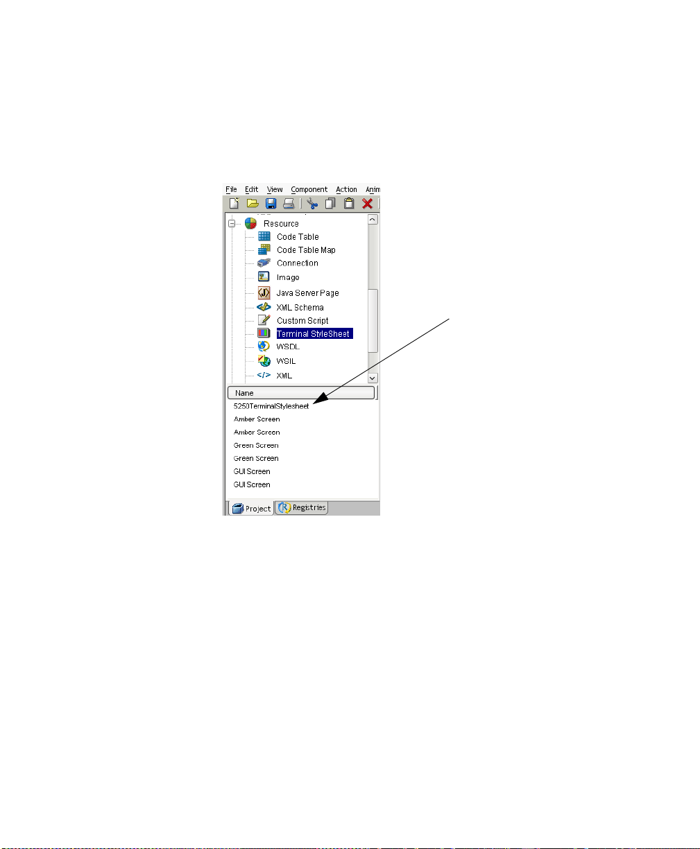
5 Click OK. The newly created style sheet resource appears in Composer’s
detail pane.
New style sheet resource
XML Templates for Your Component
Although it is not strictly necessary to do so, your 5250 Component may require
you to create XML templates so that you have sample documents for designing
your component. (For more information, see Chapter 5, “Creating XML
Templates,” in the exteNd Composer User's Guide.)
In many cases, your input documents will be designed to contain data that a
terminal operator might type into the program interactively. Likewise, the output
documents are designed to receive data returned to the screen as a result of the
operator's input. For example, in a typical business scenario, a terminal operator
may receive a phone request from a customer interested in the price or
availability of an item. The operator would typically query the host system via
his or her 5250 terminal session by entering information (such as a part number)
Getting Started with the 5250 Component Editor
25
Page 26

into a terminal when prompted. A short time later, the host responds by returning
data to the terminal screen, and the operator relays this information to the
customer . This s ession cou ld be carried out by an exteNd C omposer Web Service
that uses a 5250 Component . Th e requ est ed p a rt nu mber might be represented as
a data element in an XML input document. The looked-up data returned from the
host would appear in the component’s output document. That data might in turn
be output to a web page, or sent to another business process as XML, etc.
NOTE: Y ou r c om pon ent des ig n m ay c all for oth er x Object resources, such a s
custom scripts or C ode Table maps. If s o, i t i s a ls o b est to create these object s
before creating the 5 250 C om pon en t. Fo r m ore info rm atio n, see th e exteNd
Composer User's Guide.
26
5250 Connect User’s Guide
Page 27

3
Creating a 5250 Component Chapter 3
Before Creating a 5250 Component
As with all exteNd Composer components, the first step in cre ating a 5 250
component is to specify the XML templates needed. For more information, see
Creating a New XML Template in the Composer User’s Guide.
Once you’ve specified the XML templates, you can create a component, using th e
template’s sample d ocum e nts to rep res ent t he in put s and ou tp uts processed by
your component.
Also, as part of the process of creating a 5250 compon ent, you must select a 5250
connection or you can create a new one. See “Creating a 5 25 0 Conn ection
Resource” on page -18.
¾¾¾¾ T o c r eate a new 52 50 C omp onen t :
1 Select File>New > xObject then open the Component tab and select 5250
Terminal.
NOTE: Alternatively, under Component in the Composer window category
pane you can highlight 5250 Terminal, click the right mouse button, then
select New.
2 The “Create a New 5250 Component Wizard” appears.
Creating a 5250 Component
27
Page 28
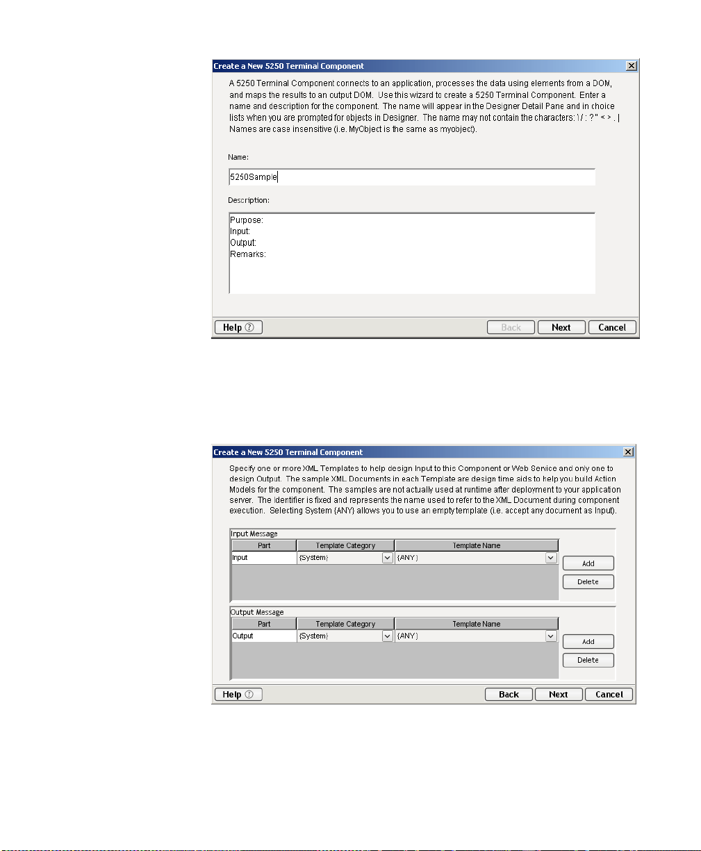
3 Enter a Name for the new 5250 Component.
4 Optionally, type Description text.
5 Click Next. The XML Input/Output Property Info panel of the New 5250
Component Wizard appears.
6 Specify the Input and Output templates as follows.
T y pe in a name for the template under Part if you wish the name to
appear in the DOM as something other than “Input”.
28
5250 Connect User’s Guide
Page 29
Select a T em pla te Cat e gory if it is dif ferent than the default category.
Select a Template Name from the list of XML templates in the selected
Template Category.
T o add additional input XML templa tes, click Add and choose a
Template Category and Template Name for each.
T o remov e an in put XML template, s elect an en try an d click Delete.
7 Select an XML template for use as an Output DOM using the same steps
outlined above.
NOTE: You can specify an input or output XML template that contains no
structure by selecting {System}{ANY} as the Input or Output template. For
more information, see “Creating an Output DOM without Using a Template” in
the User’s Guide.
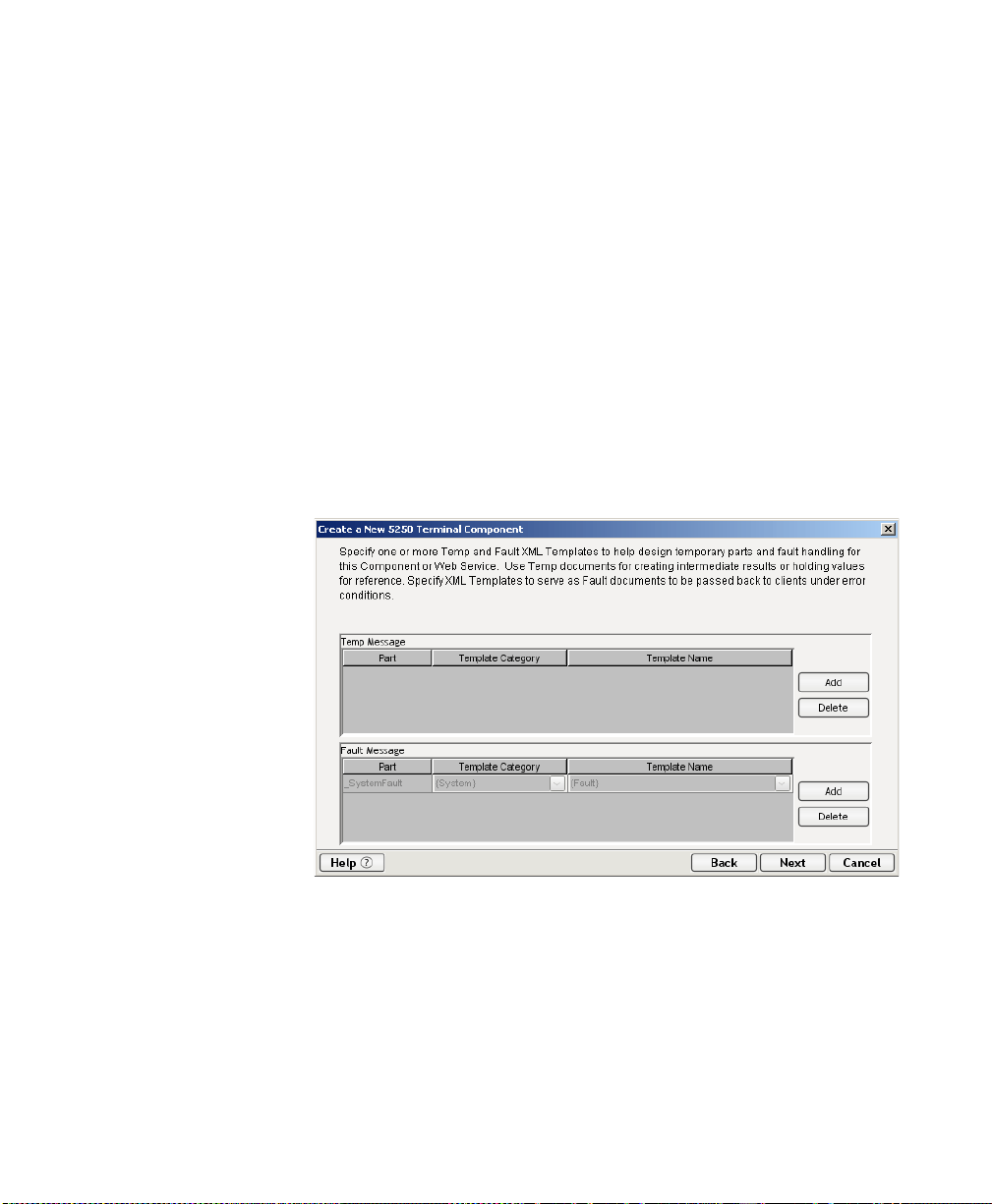
8 Click Next. The Temp/Fault XML Template Info panel appears.
9 If desired, specify a template to be used as a scratchpad under the “Temp
Message” pane of the dialog window. This can be useful if you need a place
to hold values that will only be used temporarily during the execution of
your component or are for reference only. Specify the templates as indicated
in Step 6 above.
10 Under the “Fault Message” pane, select an XML template to be used to pass
back to clients when an error condition occurs.
Creating a 5250 Component
29
Page 30
As above, to add additional temp or fault XML templates, click Add and
choose a Template Category and Template Name for each. Repeat as many
times as desired. To remove an XML template, select an entry and click
Delete.
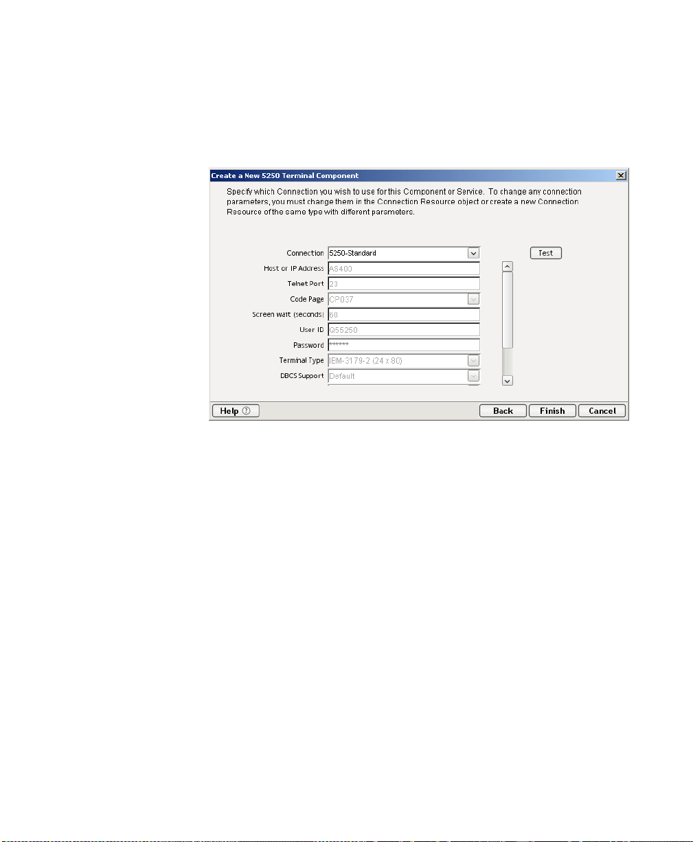
11 Click Next. The Connection Info panel of the Create a New 5250
Component Wizard appears.
12 Select a Connection name from the pull down list. For more information on
the 5250 Connection, see “Creating a 5250 Connection Resource” on page
-18.
13 Click Finish. The component is created and the 5250 Component Editor
appears.
30
5250 Connect User’s Guide
Page 31

About the 5250 Component Editor Window
The 5250 Component Editor includes all the functionality of the XML Map
Component Editor. It contains mapping panes for Input and Output XML
documents as well as an Action pane.
There are two key differences, howev er. The first is that the 5250 Component
Editor also includes a Native Environment pane common to all C onn ects. It
contains a 5250 emulator and appears black until you select the Record button in
the 5250 Component Editor window. Pressing the Record button establishes a
5250 emulation sess ion ins i de th e Nat i ve En viron ment p ane w it h the host
specified in the connection used by the 5250 comp onent. The second di fference is
the addition of a panel containing only an XML DOM called Screen Doc to th e
component editor window . This DOM presents an XML document representation
of each screen received from the ho st and is available f or r eferen ce and creating
mapping actions within the component. It is also available in the expression
builder, allowing the user to easily referen ce a screen field. Those who wish to do
so can create a quick HTML represent ation of the 52 50 screen by usin g the output
of the ScreenDoc DOM and apply a style sheet to it.
Creating a 5250 Component
31
Page 32

Input pane
Output
pane
ScreenDoc
DOM
Action Model pane
About the 5250 Native Environment Pane
The 5250 Native Env ironment pane provides 525 0 emu l atio n o f yo ur AS/400
environment. From this pane, you can perform the following:
Map data from an Input XML do cument (o r oth er avai lable DOM) and use it
as input for a 5250 screen field. For example, you could dr ag a SKU number
from an input DOM into the part field of a 5250 screen, which would then
query the host and return data associated with that part number, such as
description and price.
Map the data from the returned 5250 screen and put it into an Output XML
document (or other available DOM, e.g., Temp, MyDom, etc.).
Map header and detail information (such as an invoice with multiple line
items) from an XML document into the transaction accessed in the native
environment pane using a special Multi-Row action.
Map header and detail information (such as customer name and transaction
history) from the transaction in the native environment pane into an XML
document.
The transaction functionality of the Native Environment pane is identical to that
of a 5250 terminal or terminal emulator.
Native Environment pane
32
5250 Connect User’s Guide
Page 33

About 5250 Keyboard Support
The 5250 Native Environment pane supports the use of several attention identifier
or AID keys: Enter, Clear , PA1-3, and F1-24. The function for each attention key
varies, depending on the host application. These keys are mapped to the PC
keyboard as follows:
5250 Key PC Key
Enter Enter
Clear ESC
F1 through F12 F1 through F12
F13 through F24 Shift F1 through Shift F12
PA1 through PA3 Ctrl F1 through Ctrl F3
You can either use the keys directly from the keyboard as you create a 5250
component or you can use a k e ypad tool bar av ai labl e fro m t he View menu.
About the ScreenDoc DOM
The ScreenDoc DOM is an XML document representation of the cu rrent screen
received through the terminal data stream in th e Nativ e Env iron ment p ane. All
Mapping actions to and from t he screen display (in cluding drag and dro p) actually
reference elements in the ScreenDoc DOM. This provides you with the advantage
of being able to see and reference your familiar application screens while at the
same time working with them as XML documents.
Table 3-1
What it does
How it works
The 5250 component communicates with the ho st en viro nmen t via the b l ock
mode terminal data stream in an asynchronous fashi on. A block of dat a essentially
represents a screen. The host sends a screen bl ock that is displayed in the
component. The screen is edited by the user (and ultimately by the component you
create) and the modified screen is sent back to the host for processing after you
press an AID key.
During the recording mode, each time a screen block of data is received by the
component, four thi ngs h appen simultaneously:
Creating a 5250 Component
33
Page 34

The new screen is displayed in the Native Environment pane.
A Map Screen action appears in the Action Model. The Map Screen action is
where you will add, change, and delete actions for this particular screen.
Each time a new screen block is received as you build the component, a new
Map Screen action is created.
The Map Screen action calculates and records how many TDS fields were
received for this particular screen. This information is used for validation
purposes the next time the component is run.
The ScreenDoc DOM is refreshed with a new DOM that reflects the screen
just received. Block mode terminals send their data as a stream of fields.
These fields are defined using screen creation utilities in the host
environment (such as BMS in CICS).
The fields are represented in the ScreenDoc DOM in the or der they appear on the
screen starting from the upper left corner of the screen, moving across to the right,
then down a row starting again at the left an d s o on u ntil the entire 80x 24 or
132x27 screen area is cov e red. De pen ding on how the original scr een l ay out was
defined, there can be many fields. Some FIEL Ds are text labels o n the screen an d
usually have display attributes of protect ed ( pro t) and bright (brt). Some FIEL Ds
are for data entry and h ave an att ri bute of u np rotect ed ( unp rot ) . O ther FIELDs
contain data but are hidden from display with an attribu te of dark (d rk). Fin ally
there are special screen fields for implementing tabbin g features on the s creen,
which are protected from entering data and called bypas s fields with an attribute
of bypass.
34
The end result of listing all the TDS fields is that the ScreenDoc DOM can be quite
large. Its use i s primar ily i nte nd ed fo r f in ding hi dd en f ield s, verifying fields and
their locations by their attributes, and in cases where it is conve nient, m apping
from the ScreenDoc DOM to the Output DOM using Composer’s drag and drop
features.
NOTE: Normally it is much quicke r and more ef ficien t to map directl y to and fr om
the Native Envi ron me nt pane using drag and dro p i nstead of mapping to the
ScreenDoc DOM.
Each field in the TDS is represented in the ScreenDoc DOM as an eleme nt titled
FIELD. The ScreenDoc DOM contains as many FIELD elements as ther e are
fields in the TDS. The element displays any data defined for the field. Note that
screen fields are used for both field labels and data-en try f ields.
5250 Connect User’s Guide
Page 35

About the ScreenDoc DOM
Whenever a Map Screen action executes, a new screen is displayed in the Native
Environment Pane (NEP). Each time a screen displays in NEP, an XML
representation of the screen is created in the ScreenDoc DOM. (To make this
DOM visible, you may nee d to select a V iew from the menu bar , then the W indow
Layout choice next pick the XML Layout T a b, and finally move ScreenDoc to the
Visib le lis t and click OK. To help locate the screen cursor position
programatically, each ScreenDoc Field returned by the TDS will have an attribute
named “cursor.” The attribute value of the cursor will be “false” for all the Fields
except one whose value will be “true.” To determine which Field has the cursor,
you can write an expression to check the cursor attribute and return the Field ’s id
attribute as shown below.
In the sample list of ScreenDoc Fields in the abo ve g raphic , the XPath lo cation
ScreenDoc.XPath (“SCREEN/FIELD[@cursor= ‘true’]/@id”) would return the
number “4” indicating that Field 4 is the cu rren t curs or location.
Each element also displays the following attributes for the field:
Table 3-2
Attribute Meaning
Column The screen column (1-80) where the field begins
starting from the left
Display Display attributes defined for the field in the TDS
(prot = protected, brt = bright, unprot =
unprotected, dark = dark, bypass = bypass)
Id An absolute sequence number representing the
fields position in the TDS
Creating a 5250 Component
35
Page 36

Attribute Meaning
Length The fixed length of the field
Row The screen row (1-24) where the field begins
starting from the top
36
5250 Connect User’s Guide
Page 37

About 5250-Specific Menu Bar Items
View Menu
Keypad Tool Bar—This selection displays a keypad tool bar for the 5250
terminal keys. It is docked to the top of the native environment pan e. Y ou can dr ag
the keypad from this loca tio n, changi n g it t o a float ing w indo w. When you close
the floating window, the keypad returns to the native environmen t pane. To
remove the keypad from sight, select View, then Keypad T ool bar from the menu
bar.
Component Menu
Style Sheet—This selection displays the style sheet editor dialog. It cont ains a few
pre-defined style sheets that appear as r esources on the m ain Co mpo ser windo w.
Start/S top Recording—This selection manages the automatic creation of actions
as you interact with a screen transaction. Start will create actions as you interact
with the screen and Stop will end action creation.
Connect/Disconnect—This selection allows you to control the connection to the
host. When you are recording or animating, a con nection is au tomatically
established, so you are not required to use this button at that time. However, this
button is useful if yo u wa nt to establish a connection simply to navigate th rou gh
the 5250 environment when you are no t recor ding or animating.
Creating a 5250 Component
37
Page 38
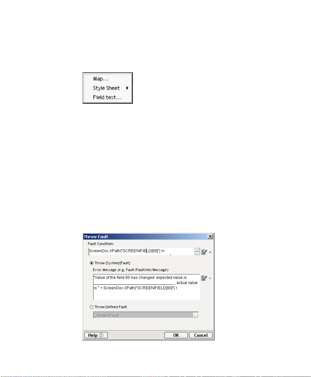
About 5250-Specific Context Menu Items
The 5250 Connect also includes context menu items that are specific to this
Connect. To view the context menu, place your curs or in a field in th e native
environment pane and click the right mouse bu tton. The con text menu app ears as
shown.
The function of the context menu items are as fo llows:
Map - Allows you to create a Map action. This is done by highlighting a source in
the Input DOM, then highlighting a source in the Native Environment Pane. As a
result, a map action is created. Also you can click the RMB in the Native
Environment pane, select Map, and an action is created. Map Screen actions will
be discussed in detail in the next chapter.
Style Sheet - Allows you to change the appearance of the native environment pane
by applying a different St y le Sheet.
Field Test - Allows you to create a Throw Fault action for the s elected field. An
expression for the fault condition will automatically be entered for you, based on
the field you clicked wh en y ou brought up the context menu . S el ect Throw
System Fault to define a new error message. (You have access to the ECMAScript
expression builder.) Alternatively, you may select Throw Defined Fault to select
a previously defined Fault Document from the dropdown list.
38
5250 Connect User’s Guide
Page 39

About 5250-Specific Buttons
The 5250 Connect includes t wo additional too ls on the component editor tool bar:
the Record button and the Connect/Disconnect button. The Record button
enables the automatic creation of actions in the Action Model as you interact with
screen transactions. The Connect/Disconnect button controls you r connect ion t o
the host. They appear as shown.
Off
Record
On Connected
Connect/Disconnect
Disconnected
Creating a 5250 Component
39
Page 40

40
5250 Connect User’s Guide
Page 41

4
Performing 5250 Actions Chapter 4
About Actions
An action is similar to a programming statement in that it takes input in the form
of parameters and performs specific tasks. Please see the chapters in the Composer
User’s Guide devoted to Actions.
Within the 5250 Component Editor, a set of instructions for processing XML
documents or communicating with non-XML data sources is created as part of an
Action Model. The Action Model performs all data mapping, data transformation,
data transfer between AS/400s and XML documents, and data tr ans fer within
components and services.
An Action Model is made up of a list of actions. All actions within an Action
Model work together. As an example, one Action Model might read in voice d ata
from a disk, retrieve data from a AS/400 inventory transaction, map the result to a
temporary XML document, mak e a conver sion, an d map t he conv erted dat a to an
output XML document.
The Action Model mentioned ab ove would be composed o f several actions. These
actions would:
Open an invoice document and perform a 5250 command to retrieve
inventory data from a AS/400 transaction.
Map the result to a temporary XML document
Convert a numeric code using a Code Table and map the result to an Output
XML document.
Performing 5250 Actions
41
Page 42

About 5250-Specific Actions
The 5250 Connect includes several actions that are specific to the 5250 and are not
a part of the core exteNd Composer pr odu ct.
5250 Action Description
Map Screen Indicates location in the Action Model to place
Multi Row This action allows you to specify the mapping of
Send Attention Key This action is created automatically by pressing
Map Screen
In addition to showing where in the Action Model a specific tran saction scr een
appears, the Map Screen action is also used for err or ch ecking . When a scr een is
first recorded, Composer saves a count of how many fields are in the screen. This
count is compared later during execution for er ror check ing to ens ure the action s
recorded will return the proper information. The Map Screen action appears in the
Action Model as shown.
Table 4-1
actions relative to a specific transaction screen.
many-to-many data relationships between a
DOM and the 5250 screen.
any Aid key. The action can be edited to change
the key sent back to the host.
42
Map Screen action
5250 Connect User’s Guide
Page 43

Multi Row
Send Attention Key
The Multi Row action can be used to input data from an XML do cumen t to a 5 250
screen, or to output data from a 5 250 screen to an XML d ocu ment. Th is action
essentially creates repeat loops within the Action Model that map multiple rows of
data automatically from one document or screen to another. The Multi Row action is
discussed in detail in “The 5250 Multi Row Wizard” on page -10 7.
Each time you select one of the AID keys displayed in the native environment tool bar ,
or its corresponding key boar d k e y, or keys, (See “About 5250 Keyboard S upp ort ” on
page 33) a Send Attention Key acti on is mapped in the Action Model .
Send Attention Key action
Double-clicking the Send Attention Key action in the Action Model displays a dialog
box that allows you to edit the key. Select from the dropdown list box the Value Key.
Click on the checkbox to override the cursor posi ti on. Edi t t he r ow an d col u mn i f
needed or click on the expression builder icon to ad d a calcu lation.
Performing 5250 Actions
43
Page 44

5250 Specific Expression Builder Extensions
TN5250 Connection Resources have two items that are accessible from Action
Expression Builder d ialogs: the UserID and Password. These are for the UserID
and Password fields that appear in the initial Composer screen when a connection
is established. The user can map these variables into the screen, which eliminates
the need for typing them into a map action that puts them into the screen.
A user may create a map action where the sour ce exp ression is defined as
$5250/LOGIN/PASSWORD and the Target XPath is defined as
$SCREENDOC/FIELD(5).
44
5250 Connect User’s Guide
Page 45

Recording a 5250 Session
The 5250 component, lik e al l UI co mpon ent s , di ffers from other components
because a major portion of the Action Model is built for you automatically. This
happens by interacting with a live session from the host in the Native Environment
pane and Composer recording you r activity as a set of actions in the Action Model.
In other components, you mu st man uall y cr eate act i ons i n th e Act ion Mo del ,
which then perform mapping, transformation, and transferring tasks.
create a 5250 component, you essentially record the requests and responses to and
from the AS/400, which generate actio ns in the Action Model pane s pecifying the
keystrokes and screen navigation required to bu ild a co mpo nent. For exam ple,
when you select the Enter button in the 5250 Nati ve Env ir onm ent pan e, t he
Action Model records th e act ion as s ho wn i n th e graphic below. In addition, you
can add actions to the Action Model just the s ame as oth er co mpon ents.
NOTE: You should be familiar with 5250 commands and the ap plication you are
interfacing into y our XML integration project in order to successfully bui ld a 5 250
component.
¾¾¾¾ T o r ec or d a 52 50 ses sion:
1 Create a 5250 component per the instructions in “Before Creating a 5250
Component” on page 27. Once created, the new 5250 comp on ent appear s in
the 5250 Component Editor window.
When you
Performing 5250 Actions
45
Page 46

Record button
NOTE: In addition to the buttons found on the XML Map Component Editor
tool bar, the 5250 Component Editor includes a Re cord and
Connect/Disconnect button as shown above.
Connect/Disconnect button
2 Click the Record button. An input screen appears in the Native Environm ent
pane and a “Map Screen” action is recorded in the Action Model pane.
46
Recorded action
5250 Connect User’s Guide
Page 47

3 Type in a UserID, Password, and any other requisite information. For the
example shown, a UserID, Password, Program/Procedure entry, and
Current Library entry are required.
4 Press the Enter key on the keyboard, or if you have the Toolbar visible
(View>Keypad Toolbar), click the Enter button. In this example, an
ENTER PART screen appears in the 5250 pane.
5 Drag the SKU data from the Input DOM to the SKU field in the 5250
ENTER PART screen. The action is recorded in the Action Model pane and
appears in the status bar.
Action Model and st atus b ar reflect
drag and drop action
Performing 5250 Actions
47
Page 48

NOTE: You can also use the Map Action to map the Input SKU to the
ENTER PART screen SKU field; however, dragging and dropping is much
quicker and easier. For more information on the Map Action feature, see the
exteNd Composer User’s Guide.
6 Click the Enter button in the 5250 pane. The 5250 ENTER PART screen is
populated with the SKU’s associated data.
7 Drag and drop an element from the ENTER PART screen to the Output
DOM, for example, the SKU number. The data you drag and drop appears in
red in the Output DOM.
48
8 Continue to drag and drop data elements from the ENTER PART screen to
the desired field in the Output Part until complete. Each time an element is
dragged from the ENTER PART screen to the Output Part an action is
recorded in the Action Model pane.
9 Click the Save button.
5250 Connect User’s Guide
Page 49

Editing a Previously Recorded Action Model
You will undoubtedly encounter times when you need to edit a previously
recorded action model. Unlike editing other components, editing a 5250
component requires extra attention. When a 5 250 comp onen t execu tes, it p lays
back a sequence of actions that expect cer tain s creens an d d ata to ap pear in order
to work properly. So when editing a component you must be careful not to make
the action model sequence inconsistent with the host transaction execution
sequence you recorded earlier.
In general, to ensure successful edits, th e following reco mmend ations app ly:
Do not cut or copy “Map Screen” action blocks and paste them into other
locations in your action model.
Carefully check and edit individual Map actions that interact with the screen
after copying and pasting them within an action model.
Use Composer's drag and drop features to add new Map action s that interact
with the screen. Animate to the line of interest in your Action Model, pause
animation, and turn on Record mode. This will prevent your Action Model
from getting out of sync with the proper ScreenDoc DOM and /or fields
within a specific ScreenDoc DOM.
Don't delete any Multi-Row related lines (or any actions for that matter) in
your Action Model during animation. This may prevent your component
from functioning properly.
Changing an Existing Action
The following procedure will explain how to change an existing action in a
previously recorded session.
¾¾¾¾ T o C ha nge an exi sting ac tion in a previously recorde d A ctio n M ode l:
1 Open the component that includes the previously recorded Action Model
that you’d like to edit. The component appears in the 5250 Component
Editor window.
Performing 5250 Actions
49
Page 50

2 Navigate to the action in the Action Model where you’d like to make your
edit and highlight the action.
3 Click the Toggle Breakpoint button. The highlighted action becomes red.
Start animation Toggle breakpoint
50
5250 Connect User’s Guide
Page 51

4 Click the Start Animation button. The animation tools become active.
Run to Breakpoint/End
5 Click the Step to Breakpoint/End button. The Action Model executes all of
the actions from the beginning to the breakpoint you set in step 3 above and
appears as shown.
Record button
Pause button
6 Click the Pause button on the animation tool bar.
7 In the Component Editor tool bar, click the Record button.
8 Execute any additional actions that you’d like to make to the Action Model.
Performing 5250 Actions
51
Page 52

9 Select File, then Save, or click the Save button on the Component Editor
10 Follow the instructions in “Using the Animation Tools” on page 58 to test
Editing Attention Keys
Whenever you press Enter on the keyboard or click o ne of the many attention
keys in the 5250 Native Environment pane while recording a session, an action is
recorded in the Action Model. An example of this is shown below.
These actions, like any o ther, can be deleted, moved, or copied, however,
remember that these actions perform navigation and will affect the running of your
component. You may also double click an Attent ion Key action and edi t it fro m a
dialog box.
tool bar.
your component.
Adding A New Action
The following procedure explains how to ad d a new action in a p revio usly
recorded session.
¾¾¾¾ T o Add a n Acti on to a p re viously rec orded Action Model:
1 Open the component that includes the previously recorded Action Model
into which you’d like to add an action. The component appears in the 5250
Component Editor window.
52
5250 Connect User’s Guide
Page 53

2 Navigate to the action in the Action Model after which you’d like to add the
action and highlight the action.
3 Click the Toggle Breakpoint button. The highlighted action becomes red.
Start animation
Toggle breakpoint
4 Click the Start Animation button. The animation tools become active.
Performing 5250 Actions
53
Page 54

Run to Breakpoint/End
5 Click the Run to Breakpoint/End button. The Action Model executes all of
the actions from the beginning to the breakpoint you set in step 3 above and
appears as shown.
Record button
54
6 Click the Pause button on the animation tool bar.
7 In the Component Editor tool bar, click the Record button.
8 Use Composer's drag and drop features to ad d new Map actions that interact
with the screen. The new action will be added directly under the highlighted
line.
5250 Connect User’s Guide
Page 55

9 Select File, then Save, or click the Save button on the Component Editor
tool bar.
10 Follow the instructi ons in “Using the Animation Tools” on page 58 to test
your component.
About Adding Alias Actions
If you are adding Map Acti o ns i n a lo op t h at will b e us ing an alias, perform the
following steps :
¾¾¾¾ T o A dd an Alias A ctio n to a pr e viou sly recorded Action Model:
1 Open a component.
2 From the Action menu, select New Action, then Map. The Map Action
dialog box displays.
3 Select the Xpath and from the drop-down list for Source, Order_Lines is
selected from the dropdown list.
4 Either type in the information, or click the Expression Builder button an d
create a new expression.
5 Create an XPath to be represented by the alias. C lick from the dropdown list
for the alias
6 Click OK.
7 The new action is inserted below the line you select. (New line is highlighted
in the screen below to show it was inserted.
Performing 5250 Actions
55
Page 56

Deleting an Action
The following procedure explains h ow to delete an action in a previous ly recorded
session
¾¾¾¾ T o D elet e an A ctio n to a previously recorded Action Model:
1 Highlight the action line you want to delete
2 Click the right mouse button and select Delete from the menu. You may also
highlight the line and press the Delete button on your keyboard.
Executing your 5250 Component
Composer includes animatio n tools that allow you to test your com ponent. On the
5250 Component Editor tool bar you ’ll find the Execute button, which allows you
to execute the entire Action Model and verify that y our com pon ent wor ks as you
intend.
56
5250 Connect User’s Guide
Page 57

¾¾¾¾ T o e xec ute a 5250 component:
1 Open a 5250 component. The 5250 Component Editor window appears.
Execute button
Animation tools
2 Select the Execute button. The actions in the Action Model execute and,
when complete, a message appears.
3 Click OK.
Performing 5250 Actions
57
Page 58

4 From the View menu, select Expand XML Documents. This expands all of
the parents, children, data elements, etc. of the XML Documents, which
allows you to see the results of the executed component. If you do not
expand the XML Docume nts, you won ’t see if the data you wanted to move
from the 5250 environment made it to the Output DOM.
Using the Animation Tools
In the Action Model, you’ll find animation tools that allow you to test a particular
section of the Action Model by setting one or more breakpoints. This way, you can
run through the actions that work pro perly, stop at the actions that are giving you
trouble, and then troubleshoot the problem actions one at a time.
NOTE: The following procedu r e i s a brief example of the f unc tio na lity o f th e
animation tools. For a complete desc rip tion of all the animation too ls an d th eir
functionality, please refer to the exteNd Co mp os er U s er’s Guide.
¾¾¾¾ T o run the an ima t ion:
1 Open a 5250 Component. The component appears in the 5250 Component
Editor window.
58
Start Animation button
NOTE: Animation and Recording are mutually exclusive modes in the
component. In order to record during animation, you must either pause, or
stop animation and then turn on record mode.
5250 Connect User’s Guide
Page 59

2 Click the Start Animation button in the Action Model tool bar, or press F5
on the keyboard. All of the tools on the tool bar become active.
Step Into button
3 Click the Step Into button. The first Map Screen action becomes
highlighted.
4 Click the Step Into button again. The instruction that enters the command
“PART” into the input field of the Native Environment pane becomes
highlighted.
5 Click the Step Into button again. The word “PART” appears in the input line
of the Native Environment pane.
Performing 5250 Actions
59
Page 60

6 Click the Step Into button again. The ENTER PART screen appears in the
Native Environment pane.
7 Click the Step Into button again. In the Action Model, the instruction for
dragging and dropping th e SKU from the Input DOM to the SKU field of the
ENTER PART screen field becomes highlighted.
60
5250 Connect User’s Guide
Page 61

8 Click the Step Into button again. The SKU data from the Input DOM
appears in the SKU field of the ENTER PART screen.
9 Click the Step Into button again. The ENTER PART screen becomes
populated with the data associated with the SKU number.
10 Click the Step Into button again. In the Action Model, the instruction to drag
the SKU data from the ENTER PART screen to the Output DOM becomes
highlighted.
Performing 5250 Actions
61
Page 62

11 Click the Step Into button again. The SKU data from the ENTER PART
screen appears in the SKU field of the Output DOM.
12 Continue to click the Step Into button until all the data elements from the
ENTER PART fields appear in the Output DOM, as shown.
62
13 Once complete, the following message appears.
5250 Connect User’s Guide
Page 63

Component with Connection Action
The Component with Connection Action is unique b ecaus e it lets y our 525 0
component call another component which will share the same connection. The
action allows you to break up a large component into a main 5250 componen t and
any number of sub-components so it is easier to maintain the Action Model. The
ability to have the main component share with the sub-component the connection
greatly reduces the amount of connection ov erhead and transaction navigation at
run time. Before you begin, determine how many sub-components you will
require and then build and save the shells (co ntaining no reco rded actions) f or
when you are ready to begin record ing.
¾¾¾¾ T o us e th e Com pon ent w ith Conne ct Ac tion
1 Create and record the basic structure of the main component to the point
where you are ready to call a sub-component. For this example, the main
component will be entitled “5250 Caller.”
2 From the Main menu, or by clicking the RMB, select New
Action>Component/w connection. The following dialog appears.
Performing 5250 Actions
63
Page 64

3 From the Component Type pull down list, select the name of the component
type. From the Component Name pull down list, select the name of the
Component.
4 Select the passed ID if you need to change it from the pull down list. Select
the returned ID if you need to change it from the pull down list. Click OK.
5 The following action appears in the map pane.
64
5250 Connect User’s Guide
Page 65

6 Animate the Main component and step into the Component with Connection
action, the sub-component will now open. See how the s creen changed to the
component entitled “5250Called.”
7 Click on the Pause button on the Animation tool bar to enable the Record
button.
Performing 5250 Actions
65
Page 66

8 Click on Record button and record the sub-component actions.
9 Save the component before stopping the animation process.
10 The 5250 Called window will now switch back to the 5250 Caller window.
66
5250 Connect User’s Guide
Page 67

Using Style Sheets in the Native Environment Pane
The Style Sheet feature of the 5250 Component E ditor provides you with optio ns
as to how you want to view the Native Environment pane.
¾¾¾¾ T o a pply a Style Sheet to the Native Env ironm ent pane:
1 From the Component menu on the 5250 Component Editor window, select
Style Sheets. The Style Sheet Editor dialog appears.
2 Choose a Style Sheet from the Style Sheet drop down list. For detailed
information on using the Style Sheet editor, see “Creating a Style Sheet
Resource” on page -23.
3 Click OK.
Performing 5250 Actions
67
Page 68

Using Other Actions in the 5250 Component Editor
In addition to the Map Screen and Multi Row action, you have all the standard Basi c
and Advanced Composer actions at your disposal as well. The complete listing of
Basic Composer Actions can be found in Chapter 7 of the Composer User’s Guide.
Chapter 8 contains a listing of the more Advanced Actions available to you.
Handling Errors and Messages
This section describes common errors you m ay s ee while ex ecuting the animation
tools.
Screen Field Count Changed
This error occurs during animation or execution of certain transactions. One condition
that can cause this is when a transaction sends one or more screens to the terminal that
do not requir e a res po ns e fro m t he us er (i.e., pressing an AID key) and then sends a
screen that does require a response. For instance, some tran saction s are designed to
display a message screen (e.g., “Please wait...”) and then display the actual transaction
screen that the user wants. The user cannot respon d to the message screen, since its
display is under the cont rol of the tran saction. The pr oblem with transact ions behaving
this way occurs during animation. As you step fr om action t o action, Com poser’s Map
Screen actions count how many fields each screen has and compares this number with
the original field count when you recorded the compo nent. Since the tran saction can
send a second screen before you h ave steppe d to its cor responding Map Screen action,
the field counts get out of s yn c.
68
5250 Connect User’s Guide
Page 69

T o correct this error, yo u must determine why the field count has changed and then
try one of the followin g rem edi al acti ons .
Double-click the Map Screen action that failed in the Action Model and
change the field count variable to the correct number of fields.
Double-click the Map Screen action, disable field count checking (see
illustration below), and wrap the whole Map Screen action block within a
Try/OnError action that will allow you to conditionally process a field count
error instead of an exception being thrown, which halts component
execution.
Map Screen field count
checking box.
The Navigator Options Dialog allows you to:
Enter the field count (number) for checking purposes. If the field count is
not correct at runtime, an error will occur . Your Try/OnError action (applied
in the previous step) will trap this error.
You MUST remember to re-select this check box before deployment.
Override connection defaults by clicking in the checkbox to allow an
override based on the seconds entered in the Screen Wait field for one
navigation action.
Set an expression that is checked each time a packet is received and
processed
Return to the next step (which may include Screen Field Count check) if the
Screen Evaluation Expression is true.
Disable the Map Screen field count checking and add your own action to
check the field count. You can do this by creating a Throw Fault action that
checks the field count (e.g.,
ScreenDoc.XPath(“count(SCREEN/FIELD)”)>68) needed for your
application. An example is shown below.
Performing 5250 Actions
69
Page 70

There are additional circumstances where field counts can get o ut of s ync. For
example:
A spooler message from a print job arrives unexpectedly. To remedy this, the
user would delete the errant Map Screen action from the Action Model.
Applications that send the same screen but with a variable number of fields.
70
5250 Connect User’s Guide
Page 71

5
Logon Componen ts,Connections
and Connection Pools Chapter 5
This section discusses certain features available in the 5250 Co nn ect des igned to
maximize performance of deployed s ervi ces.
About 5250 Terminal Session Performance
The overall performance of any service that uses back-end connectivity is usually
dependent on the time it takes to establish a connection and begin interacting with
the host. Obtaining the connection is “expensive” in terms of wait time. One
strategy for dealing with this is connection pooling, a scheme whereby an
intermediary process (whether the app server itself, o r s ome memor y-r esident
background process not associated with the server) maintains a set number of preestablished, pre-authenticated connections, and overs ees the “sh ar i ng out” of
these connections among client applications or end us ers.
Connection pooling overco mes the latency involv ed in op ening a connect ion and
authenticating to a host. But in terminal-based applications, a considerable
amount of time can be spent “drilling down” through menu selections and
navigating setup screens in order to get to the first bonafide application screen of
the session. So even when connections are reu sed through pooling, sess ion-prolog
overhead can be a serious obstacle to perfo rman ce.
Composer addresses th ese issues by providing connection po oling, managed by a
special kind of component (called a logon com pon ent) th at can m aintain an open
connection at a particular “drill-down” point in a terminal session, so that clients
can begin transactions immediately at the proper point in t he ses sio n.
When Will I Need Logon Components?
Logon Components are useful in several types of situations:
Logon Components,Connections and Connection Pools
71
Page 72

When you have a need for multiple tiers of pooling based on multiple
security challenges within your system. (For example, users may need one
set of logon credentials to get into the network, another to get into the
mainframe, and another to get into the CICS region.) Serial log-in
requirements may dictate the use of multiple logon components.
When your service needs stateful “session-based” connections.
When you need the performance advantages available through connection
pooling.
If performance under load is not a high-priority issue and your connectivity needs
are relatively uncomplicat ed, you may not need to use Logon Com ponents at all.
But there is no way to know if performance is adequate merely by testing services
at design time, on a desktop machine.
Components and services built with the 5250 Component Editor may appear to
execute quickly at design time (in Animation Mode , fo r ex ample). But in realworld conditions—which is to say under load, w it h dozen s o r even hundreds of
requests per second ar ri ving at t he se rv er—session overh ead can be a sig nificant
factor in overall transaction time. The only way to know whether you need to use
the special performance enhancement features described in this chapter is to do
load testing on a server , u nder test conditions that mimic real-world “worst c ase”
conditions.
Connection Pool Architecture
When you install th e 5250 Terminal Connect, two types of Connecti on Reso urces
are added to the Connection creation wizard : a TN52 50 C onnection and a 5250
Logon Connection (hencef ort h a Log on Connection).
The TN5250 connection is a true connection and , when used b y a 5 25 0 Terminal
component, can establish a session with a host system.
72
5250 Connect User’s Guide
Page 73

The TN5250 connection resource i s desi gned to make an ind ividual co nnectio n to the
host on an as-needed basis. The connection is made just-in-time and discarded as soon
as the client is done. It is not re used in any way. This is the type of connecti on resource
we created in Chapter 2 of this Guide.
The Logon Connection, on the other hand, is di fferent. It defines a poo l of User IDs
and passwords, each of which can make its o wn co nnection (TN52 50 ). Th e Log on
Connection also serves as an indirection layer to allow clients to connect to th e host at
exactly the point in the host program (exactly the scr een) wh ere the client needs to
start. This entry-point-location behavior is made possible by the Logon Component.
(A Logon Connection always us es a Lo gon Co mpo nent to get t o the act ual
connection.) The architecture is shown in the graph ic below.
Logon Components,Connections and Connection Pools
73
Page 74

A Connection Res our ce is always required in order to get to the host. (This is true
for any Composer service that us es 525 0 co mpo nents .) For s implicity, this
diagram shows the Connection Resource going dir ectly to the host; in the real
world, there may be intervening securi ty layers.
The Logon Component contains Actions (an action model) design ed t o find a
particular screen of interest in the host program. This drill-down location is the
effective entry point of the transaction for any up stream pro cess that u ses this
Logon Component. You can think of the Log on Com pon ent as a go -bet ween
between the physical connection (represented by the Co nnection Resou rce) and
the logic layer (represented by the 5250 Compo nent itself .
In order for a 5250 Com pon ent (at th e top of the diagram) to use a Logo n
Component, it needs to enlist the aid of a Logon Connecti on resource. The Log on
Connection is the bridg e bet ween t he 5 250 Co mpo nent and the Logon
Component.
The kinds and responsibilities of the various objects discussed above are
summarized in the following table.
Object Role
74
Connection Resource
(TN5250)
Logon Component Specialized type of component in which the
Logon Connection Specialized type of Connection Resource that
5250 Terminal
Component
5250 Connect User’s Guide
Allows a connection to be established with a
host system.
action model contains Logon, Keep Alive, and
Logoff action blocks. This component can
maintain a connection at a particular launch
screen in a host program.
associates a pool of UserIDs and passwords
with a given Logon Component type. At
runtime, connections are established for client
processes on demand (and reused), with one
Logon Component instance per connection.
Every connection in the pool provides ready
access to a given point (a particular launch
screen) in the host program, thanks to the
associated Logon Component (see above).
Contains the action model that comprises the
business logic for a particular 5250 inte ractio n
(or transaction).
Page 75

The Logon Connection’s Role in Pooling
The Logon Connection differs from the ordina ry “host-direct” connection
resource in that it manages pooling (th e sh ari ng of connection instanc es an d
Logon Component instances at runtime).
In the context of a Composer service, poo ling n ot only allows reu se of ( open )
connections at runtime, it also increases the ef fective b andwid th of a dep loyed
service. Consider the simple case where you’ve des i gn ed a 5 250 com ponent that
uses a regular connection resource. In creating the connection resource, you will
have specified a UserID and password for the res ou rce to use so that at ru ntime,
the component can log in to the host. When an actual ru nning ins tance o f y our
component is using that connection, no other instance of the componen t can log in
to the host using that same set of credentials. The bandwidth of your service is
limited to one connected instance at a time.
With a Logon Connection, on the other hand , n umero us ho st co nnect ion s can b e
maintained in a “live” state so that multiple instances of your component can
access the host (each on its own connection) without waiting. Throughput is
dramatically increased.
The diagram below shows one possib le run t ime case where th ree co mpon ent
instances (two instance of 5250 Terminal Component A and one instance of 5250
T ermin al Compon ent B ) are executing on the s erv er. Instance 1 of Component A
is using UserID ‘E’ to obtain a connection. This component has its own dedicated
instances of Logon Compon ent M an d C onn ectio n S .
T erminal Component B has just finished executing and is relinquishing its
connection (established thr oug h cred ent i als defi ned by U ID ‘F’) . Note that
because connection pooling is in effect, Component B’s downstream resources (its
Logon Component instance, M2, and its Connection ins tance, S2) are not simply
discarded; they remain live. As a result, Terminal Component A2 is able to obtain
(reuse) the M2/S2 resource instances that were prev ious ly held by Terminal
Component B.
Logon Components,Connections and Connection Pools
75
Page 76

In this diagram, Logon Connection D is associated with four connections based on
four UIDs (user IDs or credentials: A-thru-F). One is in use; another (UID ‘F’) is
alive but not being used; and two are inactive but available (i.e., valid UIDs have
been assigned, so these two connections can be mad e live at an y time).
How Many Pools Do I Need?
It’s possible for several different 5250 components to draw from the same
connection pool. It’s also possible for different components to draw fro m different
pools. This means different Logon Connect ions .
An important factor in deciding how many Logon Connection resour ces (in effect,
how many pools) your service needs is the nu mber of different start screens ( or
entry point screens) needed by the v ariou s components in your project. Suppose
T erminal Compo nent A needs to begin its work at a particular starting screen in a
host application, but you’ve also designed another component—Terminal
Component B—that needs to start on a dif ferent screen. Components A and B will
need separate Logon Conn ections, and the se parate Logon Conn ections will poi nt
to separate Logon Compo nents. (In any gi ven connection po ol, Composer object s
are shared in such a way that every user of the pool must start at the same screen.)
Pieces Required for Pooling
76
The combination of a Logon C onnection, a Logon Componen t, and its Connection
Resource form the basis of a co nnection po ol. Starting from the host layer and
working up the chain:
The Connection Resource defines the most basic parameters necessary for
establishing a connection with the host. When connection pooling is in
effect, runtime instances of this object are kept alive and reused.
The Logon Component defines the set of steps (actions) neces sary to get to a
particular entry point in the host program. (At runtime, an instance of this
component will actually carry out those steps in order to arrive at, and
maintain ready-to-use, a particular screen location in the host program.)
When connection pooling is in effect, instances of this object are kept alive
and reused.
The Logon Connection is a special type of resource that contains all the
information needed to define a connection pool. This resource is designed to
encapsulate pool-management info and does not establish host connections
directly; instead, it delegates those responsibilities to the Logon Component
(which delegates them, in turn, to the appropriate Connection Resource).
5250 Connect User’s Guide
Page 77

How Do I Implement Pooling?
T o create the various o bjects required for pooling , you’ll go through th e following
basic steps (each of which will be discuss ed in greater detail in the sections to
follow):
1 First, you’ll create a basic connection resource. The resource will be a
standard TN5250 terminal connection.
2 Next, you’ll create a Logon Component that uses the connection resource
defined in Step 1. As part of this process, you’ll create an action model
designed to navigate to a certain point in the host program.
3 You will create a Logon Connection resource, which is a specialized type of
connection resource that relies on a Logon Component (from Step 2) to
make the basic connection (through the resource defined in Step 1).
4 Finally, you’ll create a 5250 Terminal Component and associate it with the
Logon Conn ection resource of Step 3.
These steps are described in detail starting with the dis cus sio n in “Creating a
Connection Pool” fur ther b e low. Before going to that section, howev er, you
should become familiar with t he d esi g n pr i ncipl es behind the Logon Component
(and also the Logon Conn ection). W e’ll start with the Logon Component, since it’s
impossible to create a Lo gon Co nnection without using a Log on Component.
About the 5250 Logon Compon ent
The Logon Component is a special component. It has an Action Model, yet can be
used as a connection reso urce as we ll . Th e Ac ti on Mo del o f thi s t ype of
component is designed to manage a connection that will be used by multiple 5250
T ermin al Compon ents . In mos t res pects, the Logon Component is the same as a
5250 Terminal component. The differences are:
1 In a Logon Component, the Action Model is organized around connection-
management tasks. Those tasks are implemented via special actions: the
Logon Action, KeepAlive Action, and Logoff Action.
2 A Logon Component is not invoked directly by another component or
service. Its invocation is under the control of a Logon Connection.
NOTE: A Logon Componen t m ust and can only be use d in conjunction with
a Logon Connection.
Logon Components,Connections and Connection Pools
77
Page 78

Instead of calling the Logon Component directly, u sing (for example) a
Component Action, you will associate the Logon C omp onen t with a s pecial
connection resource called a Logon Connection. When y our 5250 Terminal
Component executes, it executes via the Log on Connection, which in turn
executes the Logon Component.
Logon, Keep Alive, and Logoff Actions
The Logon Component provides several screen-management capabilities that are
important factors in overall performance. These capabilities are implemented in
terms of Logon, Keep A liv e, and Lo goff actions:
Logon Actions —These actions navigate through the host environment and
park at a desired launch screen in the host system. The connection is
activated using UserIDs from the pool. The 5250 Terminal components that
subsequently reuse the connection have the performance benefit of already
being at the launch screen and won’t incur the overhead of navigating to the
launch screen as if they had come in under their own new session.
Keep Alive Actions—These actions do two important tasks. First, they
prevent the host from dropping a connection if it is not used within a
standard timeout period defined by the host. Second, these actions must
insure that the connection is always positioned at the “lau nch screen” in the
host, even after performing the Keep Alive actions needed to prevent the
connection from dropping (the first important task).
Logoff Actions—These actions exit the host environment in a manner you
prescribe for all the connections made by User IDs from the pool, when a
connection is being terminated.
78
These actions and their meanings will be discussed in greater detail below. For
now, it’s enough to know that these three action g rou ping s a re created for you
automatically when you first create a Logon Component. Note the (empty) Logon,
Keep Alive, and Logof f actio n b locks i n th e act ion model shown below:
5250 Connect User’s Guide
Page 79

Logon Actions
Actions you place in the Logon grou p ar e pr imarily con cerned with s igning into
the host security screen and then naviga tin g through the host menu system to a
launch screen where each 5250 Terminal component’s Action Model will start. It
is important that any 5250 T er minal component u sing a Logon co mponent be abl e
to start execution at the same common screen. Otherwise, the performance gains
of avoiding navigation overhead won’t be realized and more importantly, the odd
5250 terminal component won’t work.
Y ou can create actions under the Lo gon Actions block the sam e way as you would
in an ordinary 5250 T erminal Compon ent—namely by using the Record feature to
create (in real time) whatever actions are necessary in o rder to en ter s ign-o n info
such as User ID and Password (as well as your initial menu choices to arrive at the
launch screen).
NOTE: Remember to use the U se r IDs an d Pa ss w ords fro m the Log on
Connection Pool. (See the di sc us si on in “Creating a Logon Conne cti on U si ng a
Pool Connection” be low.) T o do this, you need to ma p th e tw o sp ec ial s ys tem
variables called USERID and PASSWORD to the appropriate fields on the scre en.
By specifying these tw o va riab le s, y ou make it possibl e fo r ex te Nd Com po se r to
automatically loca te and use values from the next active and fre e Po ol sl ot.
The launch screen is a common point of execu tio n for all the 5250 Terminal
Components that use the User ID pool provided by a Logon Connection. The
Logon actions in a Logon Component (wh ich are execu ted only once when a n ew
connection is established) let the calling component—your 5250 Terminal
Component—begin execution at a given sc reen in the h ost pro gram .
Logon Components,Connections and Connection Pools
79
Page 80

Maximizing Performance with the Logon Component
The Logon Actions must b e stru ct ured pr operly and therefore always b egi n and
end with a Map Screen Action as shown in the screen below.
The final Map Screen action in the Logon block g uarantees that contro l is n ot
turned over to the 5250 C omponent before the screen of in terest has arr ived in the
connection. Withou t this, the 5 250 Compo nent co uld start at an inv alid s creen,
throw an exception, and possibly corrupt a trans action. It is not neces sary fo r the
Map Screen to contain any actions, per se, but it is critical that the Map Screen
prevents control being passed to the 52 50 Comp on ent pr ematurely. It also
performs a field count check on the sc reen when it ar rives to m ake sure it is the
same screen captured during the initial recording session.
80
NOTE: Y ou may notice when an imating a Logon Compo nent that the ending Map
Screen is skipped. Thi s is norm al de si gn-t im e be ha vior. I n a pro duc tio n
environment , the ac tions in a Logon C ompone nt always execute in an interlea ved
manner with a 5250 Terminal componen t. An im atin g a Lo gon Com po nen t fro m
start to finish ac tually cr eates an abn ormal sequen ce of event s tha t would resul t in
two Map Screens be ing processed in succession, whic h is not allowed.
The performance benefit comes into play as a res ult no t on ly of con nection reus e
but launch-screen reuse. For example, if a User ID po ol o f thr ee entries is fully
used and (ultimately) reused by the execu tion of a co mpo nent fifteen times , the
overhead of navigating to a menu item that executes the transaction of interest will
occuro nly three times. Likewise, there will only be three logons to the host
because the Logon actions at the top of a Logon Component are executed only
once—when a new connection is activated (not when it is reused). This is key to
obtaining maximum performance in a high-transaction-volume production
settings.
5250 Connect User’s Guide
Page 81

NOTE: When possible, use the T ry/O n Error actio n to trap potenti al logon errors
that may be recoverable. Otherwise, th e UserID tryi ng to est ablish the failed logo n
will be discarded from the pool d ecreasing the p otential pool s ize. The pool siz e will
remain smaller until y ou ma nua lly re set the discarded con nec ti ons us in g th e
exteNd Composer Enterpri se Server Console for 525 0. See “Managing Pools” on
page -100 for mo re d et a ils.
Keep Alive Actions
The Keep Alive block is where you will place actions that “ping the host” in
whatever way necessary to keep the connection alive so that it can be r eus ed.
Keep Alive actions usually involve sending an AID key, such as <ENTER>, to the
host at some specified interval. However, if after sen ding the AID key th e sc reen
changes to some screen that is differ ent than the lau nch screen , y ou m ust be s ur e
to return the Logon Component to the launch screen in the Keep Alive section.
Failure to do so will leave the next component at an incorrect screen, causing it to
fail.
The Pool Info dialog of a Logon Connection (see discussion entitled “Creating a
Logon Connection Using a Pool Connection” below) is where you control how
often the Keep Alive actions will execute. If you specify in your Logon
Connection pool that you would like to keep a free connection active for three
minutes, but the host will normally drop a connection after two minutes of
inactivity , you can specify keyboard actions to take place at 30-secon d intervals to
let the host know the connection is still active.
Logon Components,Connections and Connection Pools
81
Page 82

Keep Alive actions will be executed multiple times, at intervals defined by the
Keep Alive parameter defi ned on th e Pool Info dialog of the Logon Co nnection.
The Inactivity Lifetime parameter (just below Keep Alive on the Pool Info dialog)
tells Composer how long it should wait, in the event the connection is not actually
used by a 5250 Terminal Component, before relinquishin g the conn ect ion.
NOTE: The execution of the Keep Alive actions of a Logon Component will not
cause the Inactivity Lifetime cloc k t o re set in the Logon Con nec tio n. O n ly a 5 250
Terminal component’s execution will reset the Inac tiv it y Lif etim e. In other words, if
a live connect ion is never actually used (bu t is merely kept ali ve by “Kee p Al iv e”
actions), then it will ti me out according to th e Inactivity Lifetime v alu e i n the Pool
Info dialog. But if the connec tion is used (by a 525 0 component) before it times out,
the timer is reset at that point.
The last action inside a Keep Alive block should be an empty but “enabled”
navigation action. If a user disables this last action, animation will not work
properly due to two consecutive empty navigation actions occurring. For example,
if an action in Logon and the first action in Keep Alive ar e dis abled, an error
occurs.
82
5250 Connect User’s Guide
Page 83

Maximizing Performance with Keep Alive Actions
Map Screens must also be processed at the beg inning and end of the Keep Alive
section.
Not only does the Keep Alive section prevent the connection fro m clos ing , bu t it
must make sure that the proper launch screen is present when the ex ecution is
completed. Therefore, the first Map Screen checks to make su re th at dur ing th e
time the connection was available but not in use, that an unexpected screen didn’t
arrive from the host. The ending Map Screen prevents the prematu re release of the
connection to the next 5250 Component. See below f or a typical Keep Alive
actions block.
Logoff Actions
Logoff actions ess enti al l y n avi gate the U ser ID properly out of the host s yst em
after a timeout.
Logoff actions execute once for a given con nection and only when a connection
times out (i.e. the Inactivity Lifetime expires) or the co nnection is closed via th e
5250 Server console.
In a “best practices” sense, it’s vitally important to make Logoff Actions
bulletproof. If an exception occurs during execution of the Logoff actions, exteNd
Composer will break its connection with the host, freeing the UserID in the pool.
But the UserID may still be active on the host. Until the host kills the UserID (from
inactivity), a subsequent attempt by the pool to log on with that UserID may fail,
unless you’ve cod ed y our logon to handle the s it uati on. Logon failures cause the
UserID to be discarded from t h e po ol , red ucing t he p otent ial po ol si ze and
performance overall. As with Lo gon and Keep Alive actions, the way to guarantee
you are on the proper screen a t th e end of the log off is to end with a Map Screen.
Logon Components,Connections and Connection Pools
83
Page 84

Logon Component Life Cycle
Each time a User ID is activated from the Logon Connection Pool, an instance of
the Logon Component is created and associated with that User ID. Then the Logon
actions are executed until the desired launch screen is reached. At this point the
5250 Terminal component execution b egins . When it is finis hed ano the r 5 250
T erminal component using the s ame Logon Connection may beg in ex ecut i ng,
starting from the same launch screen.
If no other component re quests the connection, then the connection-intance enters
an active but free state (an “idle state”) defined by the Inactivity Lifetime and
KeepAlive settings on the Pool Info dialog of the Logon Conn ection. If the Keep
Alive period (e.g. 2 minutes) is shorter than the Inactivity Lifetime (e.g. 120
minutes), then at the appropriate (2 minute) intervals, the KeepAlive actions will
be executed, preventing a host timeout and dro pped con nection; an d th e
KeepAlive Period begins an ew.
A Logon Component ’s execution lifetime is dependent on the activity of the
Logon Connection that uses it . As long as one entry in the Logon Connection poo l
is active, then one instance of the Logon Component will be in memory in a live
state. A Logon Component will go out of scope (cease executing) when the last
remaining pool entry expires due to inactivity. The only other way to stop
execution of a Logon Component is through the 5 250 Console on the Server.
About the 5250 Logon Connection
The Logon Connection is not a true connect ion ob ject like a TN52 50 Connect ion
Resource, but a pointer to a Log on Com pon ent (wh ich in tu rn co nnects to a host
either through a convent ional Connection Resource or yet mo re i nterv eni ng
Logon Connection/Log on Component pairs). The Logon Connection
encapsulates information needed to describe a pool of co nnection s. That includes
User IDs and passwords, plus pool settings involving the time interval between
retries on discarded co nnections, etc. Another func tio n of t he L ogo n C onn ect ion
is that it ensures the use of differ ent inst ances of the same Logon Component for
all the User IDs for which connections are made.
The dialogs you’ll use in setting up a pool of User IDs for a Log on Connection are
shown in the following set of illustrations. Arrows denote the buttons that lead to
continuation dialogs.
84
5250 Connect User’s Guide
Page 85

Every Logon Connection is associated with a g iven Lo gon Co mpo nent. In
addition, the Logon Con necti on pro vi des t he fol low ing U ser ID po ol
functionality:
1 It allows the specification of multiple User IDs in advance ensuring that
clients are able to secure a connection when one is needed
2 It allows the reuse of a User ID/connection once it is established to eliminate
repeated user authentications and disconnects
Logon Components,Connections and Connection Pools
85
Page 86

3 It allows a single User ID to use multiple connections if this is supported by
the host system
4 It keeps a connection active to prevent host timeouts during inactive periods
5 It lets you specify when to remove a connection from the active pool
6 It sets a timeout period to use for a fully active pool to provide a free
connection
7 It lets you specify error handling dependent on the state of the Logon
Component used by the Logon Connection
Many-to-One Relationship of Components to Logons
In order for multiple instances of a 5250 Terminal component or dif ferent 5250
T erminal components to use a same Logon Connection, the following conditions
must be met:
1 All the 5250 Terminal components must use the same Connection Resource
(thereby sharing the TN5250 Host, Port and data encoding parameters)
2 All the 5250 Terminal components must have a common launch screen in
the host system from which they can begin execution (see “About the 5250
Logon Component” above for more detail).
Connection Pooling with a Single Sign-On
If your host system s ecuri t y sup ports multiple logins from a s in gle u ser ID , y ou
may have circumstances where you wish to po ol the si ng le User ID. Th is can be
accomplished by performing the f ollowing step s:
Specify a User ID/Password in the Connection Resource used by the Logon
Component.
On the Pool Info dialog of the Logon Connection, specify a Pool Size g reater
than 1.
Do NOT check the Override the UID/PWD setting in the Pool Info dialog
of the logon Connection.
These steps will cause each pool slot to use the User ID and Password contained
in the Connection object and not use and user IDs from the pool.
86
5250 Connect User’s Guide
Page 87

Creating a Connection Pool
Overview
When creating a 5250 Terminal component, you normally first create the
Connection object it needs. Similarly, when creating the objects comprising a
Connection Pool, you must create certain o bjects firs t, starting (in es sence) at the
host and working your way backward s to the 5250 Terminal Component that will
access the host. A typical sequence of steps for creating a Co nnection Pool is :
Step One:
Create a basic host
Connection Resource
Step Two:
Create Logon Component
that uses basic Connection
Step Three:
Create Logon Connection
that uses Logon Component
Creating a Connection
This step is simple. C reat e a n ew TN525 0 C onnection Resource as desc ri bed in
“T o create a 5 250 Connection Resou rce:” on page -18. Even though you will be
using User IDs and Password s defined in th e Logon Connecti on later , yo u should
still define one in the Connection as well. This will be needed when you define the
Logon Component in the next st ep. Alte rnatively, you can simply use an existing
Connection Resource.
Logon Components,Connections and Connection Pools
Step Four:
Create standard Components
using Logon Connection
87
Page 88

Creating a Logon Component
¾¾¾¾ T o crea te a 5250 Logon Component:
1 From the Composer File menu, select New > xObject, then open the
Component tab and select 5250 Logon.
The Header Info panel of the New xObject Wizard appears.
2 Type a Name for the connection object.
88
3 Optionally, type Description text.
4 Click Next and the Connection Info panel appears.
5250 Connect User’s Guide
Page 89

5 Select a standard terminal Connection from the drop down list.
6 Click Finish and the Logon Component Editor appears.
NOTE: Recording actions follows a series of steps. The cursor must be
positioned over Logon; turn Record on; when you are done, turn Record off.
Position the cursor to KeepAlive; turn Record on; when you are done, turn
Record off. Positi on the c ursor to L ogof f; turn R eco rd on, when you are d one,
turn Record off.
7 Record Logon Actions for logging into the host and navigating to the launch
screen using the same Recording techniques described in Chapter 4 of this
Guide.
8 Edit the Logon Map actions that enter a Us er ID and Password to ins tead use
the special USERID and PASSWORD variables described in the section
titled “5250 Specific Expression Builder Extensions” in Chapter 4 of this
Guide.
Logon Components,Connections and Connection Pools
89
Page 90

9 Create the needed SEND Key actions in the KeepAlive section of the Action
Model (a quick way is to copy an existing SEND key action, Paste it, and
then modify the key code sent).
10 Record Logoff actions for properly exiting the host.
11 Save and Close the Logon Component.
Creating a Logon Connection Using a Pool Connection
¾¾¾¾ T o crea te a 525 0 Logon Connection:
1 From the Composer File menu, select New > xObject, then open the
Resource tab and select Connection or you can click on the icon. The
Header Info panel of the New xObject Wizard appears.
90
5250 Connect User’s Guide
Page 91

2 Type a Name for the connection object.
3 Optionally, type Description text.
4 Click Next and the Connection Info panel appears.
5 For the Connection Type select “5250 Logon Connection” from the drop
down list.
6 In the Connect Via control, select the Logon Component you just created.
7 Click on the Pool Info button and the Pool Info dialog appears.
Logon Components,Connections and Connection Pools
91
Page 92

8 Enter a Pool Size number. This represents the total number of connections
you wish to make available in this pool. For each connection, you will be
expected to supply a UserID/Password combination later.
9 Enter a KeepAlive time period. This number represents (in minutes) how
often you wish to execute the KeepAlive actions in the associated Logon
Component whenever the connection is active but free (i.e. not being used
by a 5250 Terminal component). The number you enter here should be less
than the Timeout period defined on the host for an inactive connection.
10 Enter an Inactivity Lifetime. This numb er represen ts (in mi nutes) h ow long
you wish to keep an active free connection available before closing out the
connection and returning it to the inactive portion of the connection pool.
Remember, that once the connection is returned to its inactive state in the
pool, it will incur the overhead of logging in and navigating host screens
when it is re-activated.
11 Enter an Entry Wai t time in seconds. This time represents how long a 5250
T erminal component will wait for a free connection when all the pool entries
are active and in use. If this time period is reached, an Exception will be
thrown to the Application Server.
92
5250 Connect User’s Guide
Page 93

12 Checking Override UID/PWD means you wish to specify User
ID/Password combinations for use in the connection pool. When checked,
this activates the Set USERIDs button. Click on the button to display the Set
USERIDs and PASSWORDS dialog.
Add
Delete Paste
On the Toolbar there are three icons: Add which adds an empty row, Delete,
which deletes a highlighted row and Paste which allows you to copy/paste
information from a spreadsheet into the table.
NOTE: Alternate and faster ways to enter data are to copy data from a
spread sheet and paste it into the table. Make sure your selection contains
two columns. The first column must contain UserID; the second Password.
Open the spreadsheet, copy the two columns and as many rows as needed.
Open the table and immediately click the Paste icon located on the toolbar.
Y ou can also copy data from tables in a Microsoft Word® document using the
same technique.
13 Enter as many USERID/PASSWORD combinations needed, until you
reach the size of the pool you specified . (If you enter mo re, then the po ol size
will be automatically adjusted to the new size.)
14 Click OK to dismiss th e “Se t User IDs and Password s” dialog and return to
the Pool Info dialog.
15 Optionally check the Pool Device Names checkbox to indicate that you wish
to specify Device Names for use in the conn ectio n pool. When checked, this
activates the Set Device Names button. Click on the button to display the Set
Device Names dialog.
Logon Components,Connections and Connection Pools
93
Page 94

NOTE: If the Enable T elnet Enviro nment checkbo x from the logon com ponent's
connection is not checked, both the Pool Device Names checkbox and th e Set
Device Names… button are disa ble d.
16 Enter the required Device Names and click OK.
On the T ool bar there are three icon s: Add which adds an empty row, Delete,
which deletes a highlighted row and Paste which allows you to copy/paste
information from a spreadsheet into the table. For more on this, see the
following Note.
94
NOTE: Alternate and faster way s t o en ter data are to copy da t a from a spread
sheet and paste it into the table. Make sure your selection contains a column
containing De vic e Names. Open the sp readsheet, copy the o lum n and as m any
rows as needed. O pe n th e table and immedia tely c lic k the Pas te ic on l oc ate d o n
the toolbar. You can als o c op y d at a from t ables in a Micros of t W ord® document
using the same tec hn iqu e.
17 Opt ionally click the Use Sequential Connections checkbox if you want
Composer to establish connections in the same order that User IDs were
listed in the “Set User IDs and Passwords” dialog. Connections will be made
in numerical sequence.
18 In the Retry discarded after field, enter a value representing the number of
minutes to wait between connection retries (attempts to reestablish a
connection).
19 In the Max retry discarded field, enter a value representing the number of
connection attempts to try before giving up (which means permanently
discarding the connection).
5250 Connect User’s Guide
Page 95

20 Optionally check the Reuse connection only if expression is true control.
This control allows you to enter an ECMAScript expression that evaluates to
true or false based on some test of the launch screen. The purpose of the
expression is to check to make sure the launch screen is the proper one each
time a new 5250 Component is about to reuse an active free connection.
Under circumstances unrelated to your Composer service, it’s possible that
the launch screen will be replaced by the host with a different screen. For
instance, if there is a system ABEND on the host, the launch screen in the
Logon Component may be replaced by a System Message screen.
NOTE: For instructions on how to create this expression, see the section
entitled: “Handling Sys tem Mes sag es” on page -128 of this Guide. Also refer
to “Maximizing Performance of 5250 Logon Connection” in this Chapte r.
The following is a sample Custom Script used to see if a particular screen is
present. If it is not, the script writes a message to the console stating that the
screen is bad and the Logon Connection is being released. This function is
called from the “Reuse connect only if expression is true” control on the
Pool Info dialog.
function checkValidLaunchScreen(ScreenDoc)
{
var screenText = ScreenDoc.XPath("SCREEN").item(0).text
if((screenText.indexOf( "MENU") != -1 || screenText.indexOf("APLS") != -1) &&
(screenText.indexOf("COMMAND UNRECOGNIZED") == -1 ||
screenText.indexOf("UNSUPP O RTE D FUNCTION") == -1))
{
return tru e ;
}
e ls e
{
java.lang.System.out.println("Warning - Releasing logon connection at bad screen");
java.lang.System.err.println("Warning - Releasing logon connection at bad screen");
return fals e ;
}
}
21 Click OK to return to the Connectio n In fo pane l.
22 Click Finish and the Logon Connection is saved.
Logon Components,Connections and Connection Pools
95
Page 96

Maximizing Performance of 5250 Logon Connection
T o prevent 5250 Components from beginning executi on on a connection t hat may
have been left on an invalid sc reen b y a prev ious 52 50 component, the Logon
Connection Resource allows the connection itself to check for the pr esence of the
launch screen. This is accomplished by using the option titled “Reuse connection
only if expression is true” on the Pool Info dialog of t h e Log on Connection. The
screen test you specify here is executed each time a 52 50 Compon ent co mpletes
execution. If the test fails, exteNd Composer will immediately disconnect from
the host, possibly leaving a dangling UserID on the host. As noted before, the host
will eventually kill the user, but the UserID may be discarded from the pool if it is
accessed again before being killed, thereby reducing the pool size and
consequently overall performance.
Another reason to use the “Reuse connection only if true” option is that you can
perform very detailed tests against the screen to make sure it is your launch screen.
While Map Screen actions do perform a screen check, they on ly loo k at th e
number of fields in the terminal data stream. In mo st ca ses, this is suf f icient.
However, it is possible two different screens can have the same number of fields
in which case the expression based test that examines the content of the scr een will
produce more rigorous results. A best pr actices ap pro ach man dates that yo u u se
this feature all the time.
Static versus Dynamically Created Documents/Elements
In some Composer applications, users have a need to place various control,
auditing, and/or meta -data in an XML d ocument. Thi s do cument may or m ay not
be in addition to the actual elements/documents being processed ( i.e. created from
an information source). If this docu ment structure and data is dy namically created
by multiple Map actions (i.e. over 100) per for mance o f th e comp onen t and
therefore the entire service may suffer . T o boost performance, create the portion of
the document structure without the dynamic content ahead of time , then load it
into the Service at runtime via an XML Interchange action and retain th e Map
actions for dynamic content. This can boost performance as much as 30% in so me
cases.
Creating a Logon Connection using a Session Connection
Sometimes, you may want the extra level of control over session parameters that
a Logon Connection afford s, without necessarily wan ting to use pooling. In this
case, you can follow the procedure outlined below.
96
5250 Connect User’s Guide
Page 97

¾¾¾¾ T o c reate a 5 250 Lo gon Co nnection:
1 From the Composer File menu, select New > xObject, then open the
Resource tab and select Connection, or you can click on the icon. The
Header Info panel of the New xObject Wizard appears.
2 Type a Name for the connection object.
3 Optionally, type Description text.
4 Click Next and the Connection Info panel appears.
5 For the Connection Type select “5250 Logon Connection” from the drop
down list.
Logon Components,Connections and Connection Pools
97
Page 98

6 In the Connect Via control, select the Logon Component you just created.
7 The Screen wait (seconds) field displays the amount of time in seconds that
a 5250 Terminal component will wait for a the next screen to arrive in the
Map Action Pane.
8 Click the Session Connections radio button and then on the Session Info
button.
9 The Keep Alive (minutes) number represents (in minutes) how often you
wish to execute the Keep Alive actions in the associated Logon Component
whenever the connection is active but free (i.e. not being used by a 5250
Terminal component). The number you enter here should be less than the
Timeout period defined on the host for an inactive connection.
10 The Inactivity Lifetime (minutes) number represents (in minutes) how long
you wish to keep an active free connection available before closing out the
connection and returning it to the inactive portion of the connection pool.
Remember, that once the connection is returned to its inactive state in the
pool, it will incur the overhead of logging in and navigating host screens
when it is re-activated.
11 Click in the checkmark box if you want to Reuse connection only if
expression is true (see discussion above). If you choose to do so, the
expression field automatically displays and you can click on the expression
icon to display the if the expression is true dialog.
98
5250 Connect User’s Guide
Page 99

Creating a 5250 Terminal Component That Uses Pooled Connections
At this point, you are ready to create a 5250 Logon Component that can use the
Connection Pool. For the mos t part, you will bu ild the component as yo u would a
normal 5250 Terminal Component, the only differen ce being the Con nection you
specify on the Connection Panel of the New Component Wizard. (You’ll specify a
Logon Connection inst ead o f a r egul ar TN 525 0 C onn ect ion.)
¾¾¾¾ T o c re ate a 5 250 Terminal Component:
1 From the Composer File menu, select New > xObject, then open the
Component tab and select 5250 Terminal. The Header Info panel of the
New xObject Wizard appears:
2 Type a Name for the component.
3 Optionally, type Description text.
4 Click Next and the XML Property Info panel appears.
5 Select the necessary Input and Output Templates and click Next, and the
Temp/Fault panel appears.
6 Select the necessary Temp and Fault Templates and click Next, and the
Connection Info panel appears.
7 Select the Logon Connection you created and click on Next, and the
Component editor appears.
8 Build the component according to the instructions found in “To create a new
5250 Component:” on page -27.
Logon Components,Connections and Connection Pools
99
Page 100

Maximizing Performance of 5250 Terminal Components
Once the launch screen is obtained by the logon Compo nent’s logon actions, it is
handed to the 5250 Terminal Component that uses the connection. Then the 5250
T erminal compo nent (when finished executing) leaves the screen handler back at
the launch screen. If th e 52 50 C omp on ent fini s hes w it hou t being on t he la u nch
screen,(i.e. it releases the connection back to the pool with an invalid screen) the n
it is possible that all subsequent 5250 Components that use the connection may
throw exceptions rendering the connection useless. It also will degrade overall
performance and possibly cause data integrity problems within the component
processing.
Once again, ensure that the launch screen is pr esent. The la st action to execu te in
a 5250 Component must be a Map Screen that checks for the launch screen. This
can be tricky if your compon ent has many d ecision paths t hat may in dependently
end component execution. You must be sure that each path ends with a Map
Screen action.
Errors Involving Logon Connections
If connection pooling is used, and there has been an attemp t to log on with a b ad
UserID or Password, that connection instance will not be usable and that member
of the pool will be s ki pp ed ov er i n su bs equen t con necti on requests. An error
message will be sent to the server log saying “Logon connection in pool <Pool
name> was discarded for User ID <User ID>.” You should check for messages of
this sort during p repr odu ctio n t es t ing an d/ or any time performance issu es ar i se.
There are a few different steps you can take to resolve a bad UserID or Password:
Alert your System Administrator that the UserID and Password doesn’t
work. If the administrator checks the ID and Password and it is good, then
reset the server from the Connection Manager Console.
If the UserID and Password is bad, remove it from the connection pool.
Managing Pools
Connections pools can be man aged through the 5250 Cons ol e Sc reen.
¾¾¾¾ How to Access the Console
1 If you are using the Novell exteNd Application Server, log on to your server
via your web browser using http://localhost/SilverMaster50 (or whatever
is appropriate for the version in use). In this example, Novell exteNd App
Server 5.0 is used.
100
5250 Connect User’s Guide
 Loading...