

Page 1

Novell Business Continuity Clustering 1.1 for NetWare Administration Guide
Novell
Business Continuity Clustering
novdocx (en) 11 December 2007
for NetWare
1.1
ADMINISTRATION GUIDE
February 15, 2008
®
www.novell.com
Page 2

Legal Notices
Novell, Inc., makes no representations or warranties with respect to the contents or use of this documentation, and
specifically disclaims any express or implied warranties of merchantability or fitness for any particular purpose.
Further, Novell, Inc., reserves the right to revise this publication and to make changes to its content, at any time,
without obligation to notify any person or entity of such revisions or changes.
Further, Novell, Inc., makes no representations or warranties with respect to any software, and specifically disclaims
any express or implied warranties of merchantability or fitness for any particular purpose. Further, Novell, Inc.,
reserves the right to make changes to any and all parts of Novell software, at any time, without any obligation to
notify any person or entity of such changes.
Any products or technical information provided under this Agreement may be subject to U.S. export controls and the
trade laws of other countries. You agree to comply with all export control regulations and to obtain any required
licenses or classification to export, re-export or import deliverables. You agree not to export or re-export to entities on
the current U.S. export exclusion lists or to any embargoed or terrorist countries as specified in the U.S. export laws.
You agree to not use deliverables for prohibited nuclear, missile, or chemical biological weaponry end uses. See the
Novell International Trade Services Web page (http://www.novell.com/info/exports/) for more information on
exporting Novell software. Novell assumes no responsibility for your failure to obtain any necessary export
approvals.
novdocx (en) 11 December 2007
Copyright © 2007-2008 Novell, Inc. All rights reserved. No part of this publication may be reproduced, photocopied,
stored on a retrieval system, or transmitted without the express written consent of the publisher.
Novell, Inc., has intellectual property rights relating to technology embodied in the product that is described in this
document. In particular, and without limitation, these intellectual property rights may include one or more of the U.S.
patents listed on the Novell Legal Patents Web page (http://www.novell.com/company/legal/patents/) and one or
more additional patents or pending patent applications in the U.S. and in other countries.
Novell, Inc.
404 Wyman Street, Suite 500
Waltham, MA 02451
U.S.A.
www.novell.com
Online Documentation: To access the latest online documentation for this and other Novell products, see
the Novell Documentation Web page (http://www.novell.com/documentation).
Page 3

Novell Trademarks
For Novell Trademarks, see the Novell Trademark and Service Mark list (http://www.novell.com/company/legal/
trademarks/tmlist.html).
Third-Party Materials
All third-party trademarks are the property of their respective owners.
novdocx (en) 11 December 2007
Page 4

novdocx (en) 11 December 2007
Page 5

Contents
About This Guide 9
1Overview 11
1.1 Disaster Recovery Implications . . . . . . . . . . . . . . . . . . . . . . . . . . . . . . . . . . . . . . . . . . . . . . . . 11
1.2 Disaster Recovery Implementations . . . . . . . . . . . . . . . . . . . . . . . . . . . . . . . . . . . . . . . . . . . . 11
1.2.1 Stretch Clusters vs. Cluster of Clusters. . . . . . . . . . . . . . . . . . . . . . . . . . . . . . . . . . . 12
1.2.2 Novell Business Continuity Clusters . . . . . . . . . . . . . . . . . . . . . . . . . . . . . . . . . . . . . 15
1.2.3 Usage Scenarios . . . . . . . . . . . . . . . . . . . . . . . . . . . . . . . . . . . . . . . . . . . . . . . . . . . . 16
2 Installation and Setup 19
2.1 Requirements . . . . . . . . . . . . . . . . . . . . . . . . . . . . . . . . . . . . . . . . . . . . . . . . . . . . . . . . . . . . . 19
2.1.1 NetWare 6.5 SP 5 or SP 6 (OES 1 SP2 or SP3 NetWare) . . . . . . . . . . . . . . . . . . . . 19
2.1.2 Novell eDirectory 8.8 . . . . . . . . . . . . . . . . . . . . . . . . . . . . . . . . . . . . . . . . . . . . . . . . . 20
2.1.3 Novell Cluster Services 1.8.2 for NetWare . . . . . . . . . . . . . . . . . . . . . . . . . . . . . . . . 20
2.1.4 OpenSLP. . . . . . . . . . . . . . . . . . . . . . . . . . . . . . . . . . . . . . . . . . . . . . . . . . . . . . . . . . 20
2.1.5 OpenWBEM . . . . . . . . . . . . . . . . . . . . . . . . . . . . . . . . . . . . . . . . . . . . . . . . . . . . . . . 21
2.1.6 BASH. . . . . . . . . . . . . . . . . . . . . . . . . . . . . . . . . . . . . . . . . . . . . . . . . . . . . . . . . . . . . 21
2.1.7 LIBC . . . . . . . . . . . . . . . . . . . . . . . . . . . . . . . . . . . . . . . . . . . . . . . . . . . . . . . . . . . . . 21
2.1.8 autoexec.ncf File . . . . . . . . . . . . . . . . . . . . . . . . . . . . . . . . . . . . . . . . . . . . . . . . . . . . 21
2.1.9 Shared Disk Systems . . . . . . . . . . . . . . . . . . . . . . . . . . . . . . . . . . . . . . . . . . . . . . . . 21
2.1.10 Link Speeds. . . . . . . . . . . . . . . . . . . . . . . . . . . . . . . . . . . . . . . . . . . . . . . . . . . . . . . . 21
2.2 Installing Identity Manager . . . . . . . . . . . . . . . . . . . . . . . . . . . . . . . . . . . . . . . . . . . . . . . . . . . . 21
2.3 Installing Novell Business Continuity Cluster Software . . . . . . . . . . . . . . . . . . . . . . . . . . . . . . 23
2.3.1 Business Continuity Cluster Licensing . . . . . . . . . . . . . . . . . . . . . . . . . . . . . . . . . . . 23
2.3.2 Running the Business Continuity Cluster Installation Program . . . . . . . . . . . . . . . . . 23
2.3.3 Business Continuity Cluster Component Locations . . . . . . . . . . . . . . . . . . . . . . . . . 25
2.4 Configuring File System Mirroring . . . . . . . . . . . . . . . . . . . . . . . . . . . . . . . . . . . . . . . . . . . . . . 25
2.4.1 Configuring NSS Mirroring . . . . . . . . . . . . . . . . . . . . . . . . . . . . . . . . . . . . . . . . . . . . 26
2.4.2 Configuring SAN-Based Mirroring . . . . . . . . . . . . . . . . . . . . . . . . . . . . . . . . . . . . . . . 29
2.4.3 LUN Masking. . . . . . . . . . . . . . . . . . . . . . . . . . . . . . . . . . . . . . . . . . . . . . . . . . . . . . . 29
2.5 Setting Up Novell Business Continuity Cluster Software . . . . . . . . . . . . . . . . . . . . . . . . . . . . . 29
2.5.1 Configuring Business-Continuity-Specific IDM Drivers . . . . . . . . . . . . . . . . . . . . . . . 29
2.5.2 Configuring Clusters for Business Continuity . . . . . . . . . . . . . . . . . . . . . . . . . . . . . . 35
2.5.3 Configuring Cluster Resources for Business Continuity . . . . . . . . . . . . . . . . . . . . . . 41
2.6 Managing a Novell Business Continuity Cluster . . . . . . . . . . . . . . . . . . . . . . . . . . . . . . . . . . . 43
2.6.1 Migrating a Cluster Resource to Another Cluster . . . . . . . . . . . . . . . . . . . . . . . . . . . 44
2.6.2 Changing Cluster Peer Credentials. . . . . . . . . . . . . . . . . . . . . . . . . . . . . . . . . . . . . . 45
2.6.3 Viewing the Current Status of a Business Continuity Cluster . . . . . . . . . . . . . . . . . . 46
2.6.4 Generating a Cluster Report . . . . . . . . . . . . . . . . . . . . . . . . . . . . . . . . . . . . . . . . . . . 46
2.6.5 Disabling Business Continuity Cluster Resources. . . . . . . . . . . . . . . . . . . . . . . . . . . 47
2.6.6 Business Continuity Cluster Console Commands . . . . . . . . . . . . . . . . . . . . . . . . . . . 47
2.7 Business Continuity Cluster Failure Types . . . . . . . . . . . . . . . . . . . . . . . . . . . . . . . . . . . . . . . 49
2.7.1 SAN-based Mirroring Failure Types and Responses . . . . . . . . . . . . . . . . . . . . . . . . 50
2.7.2 Host-Based Mirroring Failure Types and Responses . . . . . . . . . . . . . . . . . . . . . . . . 51
novdocx (en) 11 December 2007
3 Upgrading BCC 53
3.1 Upgrading BCC 1.0 to BCC 1.1 for NetWare. . . . . . . . . . . . . . . . . . . . . . . . . . . . . . . . . . . . . . 53
3.1.1 Upgrading NetWare. . . . . . . . . . . . . . . . . . . . . . . . . . . . . . . . . . . . . . . . . . . . . . . . . . 53
Contents 5
Page 6

3.1.2 Installing or Upgrading IDM . . . . . . . . . . . . . . . . . . . . . . . . . . . . . . . . . . . . . . . . . . . . 54
3.1.3 Installing BCC 1.1 . . . . . . . . . . . . . . . . . . . . . . . . . . . . . . . . . . . . . . . . . . . . . . . . . . . 54
3.1.4 Resetting BCC Administrative User Credentials . . . . . . . . . . . . . . . . . . . . . . . . . . . . 54
3.1.5 Authorizing the BCC Administrative User . . . . . . . . . . . . . . . . . . . . . . . . . . . . . . . . . 54
3.1.6 Verifying SAN Scripts. . . . . . . . . . . . . . . . . . . . . . . . . . . . . . . . . . . . . . . . . . . . . . . . . 55
3.1.7 Deleting and Re-Creating BCC IDM Drivers . . . . . . . . . . . . . . . . . . . . . . . . . . . . . . . 55
3.2 Upgrading BCC 1.0 to BCC 1.1 for Linux . . . . . . . . . . . . . . . . . . . . . . . . . . . . . . . . . . . . . . . . . 55
4 Troubleshooting BCC 1.1 57
4.1 Cluster Connection States . . . . . . . . . . . . . . . . . . . . . . . . . . . . . . . . . . . . . . . . . . . . . . . . . . . . 57
4.2 Driver Ports. . . . . . . . . . . . . . . . . . . . . . . . . . . . . . . . . . . . . . . . . . . . . . . . . . . . . . . . . . . . . . . . 59
4.3 Excluded Users . . . . . . . . . . . . . . . . . . . . . . . . . . . . . . . . . . . . . . . . . . . . . . . . . . . . . . . . . . . . 59
4.4 Security Equivalent User . . . . . . . . . . . . . . . . . . . . . . . . . . . . . . . . . . . . . . . . . . . . . . . . . . . . . 60
4.5 Certificates . . . . . . . . . . . . . . . . . . . . . . . . . . . . . . . . . . . . . . . . . . . . . . . . . . . . . . . . . . . . . . . . 61
4.6 Clusters Can’t Communicate . . . . . . . . . . . . . . . . . . . . . . . . . . . . . . . . . . . . . . . . . . . . . . . . . . 61
4.7 BCC Startup Flags . . . . . . . . . . . . . . . . . . . . . . . . . . . . . . . . . . . . . . . . . . . . . . . . . . . . . . . . . . 62
4.7.1 Using BCC Startup Flags . . . . . . . . . . . . . . . . . . . . . . . . . . . . . . . . . . . . . . . . . . . . . . 62
4.8 Problems With BCC Installation on NetWare . . . . . . . . . . . . . . . . . . . . . . . . . . . . . . . . . . . . . . 62
4.9 IDM Drivers for Cluster Synchronization Do Not Start . . . . . . . . . . . . . . . . . . . . . . . . . . . . . . . 63
4.10 IDM Drivers Do Not Synchronize Objects from One Cluster to Another. . . . . . . . . . . . . . . . . . 63
4.11 Tracing IDM . . . . . . . . . . . . . . . . . . . . . . . . . . . . . . . . . . . . . . . . . . . . . . . . . . . . . . . . . . . . . . . 64
4.12 Peer Cluster Communication Not Working . . . . . . . . . . . . . . . . . . . . . . . . . . . . . . . . . . . . . . . . 65
4.13 Administration of Peer Clusters Not Functional . . . . . . . . . . . . . . . . . . . . . . . . . . . . . . . . . . . . 65
4.14 Resource Does Not Migrate to Another Cluster . . . . . . . . . . . . . . . . . . . . . . . . . . . . . . . . . . . . 65
4.15 Resource Cannot Be Brought Online . . . . . . . . . . . . . . . . . . . . . . . . . . . . . . . . . . . . . . . . . . . . 65
4.16 Dumping Syslog on NetWare . . . . . . . . . . . . . . . . . . . . . . . . . . . . . . . . . . . . . . . . . . . . . . . . . . 66
4.17 Slow Failovers . . . . . . . . . . . . . . . . . . . . . . . . . . . . . . . . . . . . . . . . . . . . . . . . . . . . . . . . . . . . . 66
4.18 Resource Script Search and Replace Functions Do Not Work . . . . . . . . . . . . . . . . . . . . . . . . 66
4.19 Virtual NCP Server IP Addresses Won’t Change . . . . . . . . . . . . . . . . . . . . . . . . . . . . . . . . . . . 66
4.20 IP Address, Virtual Server DN, or Pool Name Does Not Appear on the iManager Cluster
Configuration Page. . . . . . . . . . . . . . . . . . . . . . . . . . . . . . . . . . . . . . . . . . . . . . . . . . . . . . . . . . 67
4.21 Blank Error String iManager Error Appears While Bringing a Resource Online. . . . . . . . . . . . 68
4.22 Best Practices. . . . . . . . . . . . . . . . . . . . . . . . . . . . . . . . . . . . . . . . . . . . . . . . . . . . . . . . . . . . . . 68
4.23 Mapping Drives in Login Scripts . . . . . . . . . . . . . . . . . . . . . . . . . . . . . . . . . . . . . . . . . . . . . . . . 68
4.24 Mapping Drives to Home Directories Using the %HOME_DIRECTORY Variable . . . . . . . . . . 69
4.25 BCC Error Codes . . . . . . . . . . . . . . . . . . . . . . . . . . . . . . . . . . . . . . . . . . . . . . . . . . . . . . . . . . . 70
novdocx (en) 11 December 2007
5 Virtual IP Addresses 73
5.1 Virtual IP Address Definitions and Characteristics . . . . . . . . . . . . . . . . . . . . . . . . . . . . . . . . . . 73
5.1.1 Definitions . . . . . . . . . . . . . . . . . . . . . . . . . . . . . . . . . . . . . . . . . . . . . . . . . . . . . . . . . 73
5.1.2 Characteristics . . . . . . . . . . . . . . . . . . . . . . . . . . . . . . . . . . . . . . . . . . . . . . . . . . . . . . 74
5.2 Virtual IP Address Benefits. . . . . . . . . . . . . . . . . . . . . . . . . . . . . . . . . . . . . . . . . . . . . . . . . . . . 74
5.2.1 High Availability . . . . . . . . . . . . . . . . . . . . . . . . . . . . . . . . . . . . . . . . . . . . . . . . . . . . . 74
5.2.2 Unlimited Mobility . . . . . . . . . . . . . . . . . . . . . . . . . . . . . . . . . . . . . . . . . . . . . . . . . . . . 77
5.3 Other Added Features . . . . . . . . . . . . . . . . . . . . . . . . . . . . . . . . . . . . . . . . . . . . . . . . . . . . . . . 77
5.3.1 Support for Host Mask . . . . . . . . . . . . . . . . . . . . . . . . . . . . . . . . . . . . . . . . . . . . . . . . 77
5.3.2 Source Address Selection for Outbound Connections . . . . . . . . . . . . . . . . . . . . . . . . 77
5.4 Reducing the Consumption of Additional IP Addresses . . . . . . . . . . . . . . . . . . . . . . . . . . . . . . 78
5.5 Configuring Virtual IP Addresses . . . . . . . . . . . . . . . . . . . . . . . . . . . . . . . . . . . . . . . . . . . . . . . 79
5.5.1 Displaying Bound Virtual IP Addresses . . . . . . . . . . . . . . . . . . . . . . . . . . . . . . . . . . . 80
6 Novell Business Continuity Clustering 1.1 for NetWare Administration Guide
Page 7

A Implementing a Multiple-Tree BCC 81
A.1 Copying User Objects Using IDM . . . . . . . . . . . . . . . . . . . . . . . . . . . . . . . . . . . . . . . . . . . . . . 81
A.2 Configuring User Object Synchronization . . . . . . . . . . . . . . . . . . . . . . . . . . . . . . . . . . . . . . . . 81
A.3 Creating SSL Certificates . . . . . . . . . . . . . . . . . . . . . . . . . . . . . . . . . . . . . . . . . . . . . . . . . . . . 82
A.4 Synchronizing IDM Drivers . . . . . . . . . . . . . . . . . . . . . . . . . . . . . . . . . . . . . . . . . . . . . . . . . . . 83
A.5 Preventing IDM Synchronization Loops. . . . . . . . . . . . . . . . . . . . . . . . . . . . . . . . . . . . . . . . . . 83
A.6 Migrating Resources to Another Cluster . . . . . . . . . . . . . . . . . . . . . . . . . . . . . . . . . . . . . . . . . 85
B Setting Up Auto-Failover 87
B.1 Enabling Auto-Failover . . . . . . . . . . . . . . . . . . . . . . . . . . . . . . . . . . . . . . . . . . . . . . . . . . . . . . 87
B.2 Creating an Auto-Failover Policy . . . . . . . . . . . . . . . . . . . . . . . . . . . . . . . . . . . . . . . . . . . . . . . 88
B.3 Refining the Auto-Failover Policy. . . . . . . . . . . . . . . . . . . . . . . . . . . . . . . . . . . . . . . . . . . . . . . 88
B.4 Adding or Editing Monitor Configurations . . . . . . . . . . . . . . . . . . . . . . . . . . . . . . . . . . . . . . . . 89
C Security Considerations 91
C.1 Security Features. . . . . . . . . . . . . . . . . . . . . . . . . . . . . . . . . . . . . . . . . . . . . . . . . . . . . . . . . . . 91
C.2 Security Configuration . . . . . . . . . . . . . . . . . . . . . . . . . . . . . . . . . . . . . . . . . . . . . . . . . . . . . . . 91
C.2.1 BCC Configuration Settings . . . . . . . . . . . . . . . . . . . . . . . . . . . . . . . . . . . . . . . . . . . 92
C.2.2 Security Information for Other Products . . . . . . . . . . . . . . . . . . . . . . . . . . . . . . . . . . 95
C.3 Other Security Considerations . . . . . . . . . . . . . . . . . . . . . . . . . . . . . . . . . . . . . . . . . . . . . . . . . 96
novdocx (en) 11 December 2007
D Documentation Updates 97
D.1 February 15, 2008 (Updates). . . . . . . . . . . . . . . . . . . . . . . . . . . . . . . . . . . . . . . . . . . . . . . . . . 97
D.1.1 Installation and Setup . . . . . . . . . . . . . . . . . . . . . . . . . . . . . . . . . . . . . . . . . . . . . . . . 97
D.1.2 Troubleshooting BCC 1.1 . . . . . . . . . . . . . . . . . . . . . . . . . . . . . . . . . . . . . . . . . . . . . 98
Contents 7
Page 8

novdocx (en) 11 December 2007
8 Novell Business Continuity Clustering 1.1 for NetWare Administration Guide
Page 9

About This Guide
novdocx (en) 11 December 2007
This guide describes how to install, configure, and manage Novell® Business Continuity Clustering
®
for NetWare
Chapter 1, “Overview,” on page 11
Chapter 2, “Installation and Setup,” on page 19
Chapter 3, “Upgrading BCC,” on page 53
Chapter 4, “Troubleshooting BCC 1.1,” on page 57
Chapter 5, “Virtual IP Addresses,” on page 73
Appendix A, “Implementing a Multiple-Tree BCC,” on page 81
Appendix B, “Setting Up Auto-Failover,” on page 87
Appendix C, “Security Considerations,” on page 91
. The guide is divided into the following sections:
Audience
This guide is intended for intended for anyone involved in installing, configuring, and managing
Novell Cluster Services.
Feedback
We want to hear your comments and suggestions about this manual and the other documentation
included with this product. Please use the User Comments feature at the bottom of each page of the
online documentation, or go to www.novell.com/documentation/feedback.html and enter your
comments there.
Documentation Updates
The latest version of this Novell Business Continuity Clustering for NetWare Administration Guide
is available on the BCC 1.1 Documentation Web site (http://www.novell.com/documentation/
bcc11/index.html).
Documentation Conventions
In Novell documentation, a greater-than symbol (>) is used to separate actions within a step and
items in a cross-reference path.
®
A trademark symbol (
, TM, etc.) denotes a Novell trademark. An asterisk (*) denotes a third-party
trademark.
About This Guide
9
Page 10

novdocx (en) 11 December 2007
10 Novell Business Continuity Clustering 1.1 for NetWare Administration Guide
Page 11

1
Overview
novdocx (en) 11 December 2007
1
As corporations become more international, fueled in part by the reach of the World Wide Web, the
requirement for service availability has increased. Novell
the ability to maintain 24x7x365 data and application services to their users while still being able to
perform maintenance and upgrades on their systems.
In the past few years, natural disasters (ice storms, earthquakes, hurricanes, tornadoes, and fires)
have caused unplanned outages of entire data centers. In addition, US federal agencies have realized
the disastrous effects that terrorist attacks could have on the US economy when corporations lose
their data and the ability to perform critical business practices. This has resulted in initial
recommendations for corporations to build mirrored or replicated data centers that are
geographically separated by 300 km or more (The minimum acceptable distance being 200 km).
Many companies have built and deployed geographically mirrored data centers. The problem is that
setting up and maintaining the two or more centers is a very manual process that takes a great deal of
planning and synchronizing. Even configuration changes have to be carefully planned and
replicated. One mistake and the redundant site is no longer able to effectively take over in the event
of a disaster.
®
Cluster Services™ offers corporations
1.1 Disaster Recovery Implications
The implications of disaster recovery are directly tied to your data. Is your data mission critical? In
many instances, critical systems and data drive the business. If these services stop, the business
stops. When calculating the cost of downtime, some things to consider are
File transfers and file storage
E-mail, calendaring and collaboration
Web hosting
Critical databases
Productivity
Reputation
Continuous availability of critical business systems is no longer a luxury, it is a competitive business
requirement.The Gartner Group estimates that 40% of enterprises that experience a disaster will go
out of business in five years and only 15% of enterprises have a full-fledged business continuity plan
that goes beyond core technology and infrastructure.
1.2 Disaster Recovery Implementations
There are two main Novell Cluster Services implementations that you can use to achieve your
desired level of disaster recovery. These include a stretch cluster and a cluster of clusters. The
Novell Business Continuity Cluster product automates some of the configuration and processes used
in a cluster of clusters.
Section 1.2.1, “Stretch Clusters vs. Cluster of Clusters,” on page 12
Section 1.2.2, “Novell Business Continuity Clusters,” on page 15
Overview
11
Page 12

Section 1.2.3, “Usage Scenarios,” on page 16
1.2.1 Stretch Clusters vs. Cluster of Clusters
“Stretch Clusters” on page 12
“Cluster of Clusters” on page 12
“Implementation Comparison” on page 14
Stretch Clusters
A stretch cluster consists of one cluster in which the nodes in the cluster are located in
geographically separate areas. All nodes in the cluster must be in the same eDirectory™ tree. In this
architecture, the data is mirrored between two data centers that are geographically separated. All the
machines in both data centers are part of one cluster, so that if a disaster occurs in one data center,
the other automatically takes over.
Figure 1-1 Stretch Cluster
novdocx (en) 11 December 2007
Building A Building B
Ethernet Switch Ethernet Switch
Server 2
Fibre Channel
Switch
Fibre Channel
Disk Array
Site 1
Cluster of Clusters
Server 3Server 1 Server 4
8-node cluster stretched
between two sites
WAN
Cluster
Heartbeat
SAN
Disk blocks
Server 6 Server 7Server 5 Server 8
Fibre Channel
Switch
Fibre Channel
Disk Array
Site 2
A cluster of clusters consists of two or more clusters in which each cluster is located in a
geographically separate area. A cluster of clusters provides the ability to fail over selected cluster
resources or all cluster resources from one cluster to another cluster. Typically, replication of data
blocks between SANs is performed by SAN hardware, but it can be done by host-based mirroring
for synchronous replication over short distances.
12 Novell Business Continuity Clustering 1.1 for NetWare Administration Guide
Page 13
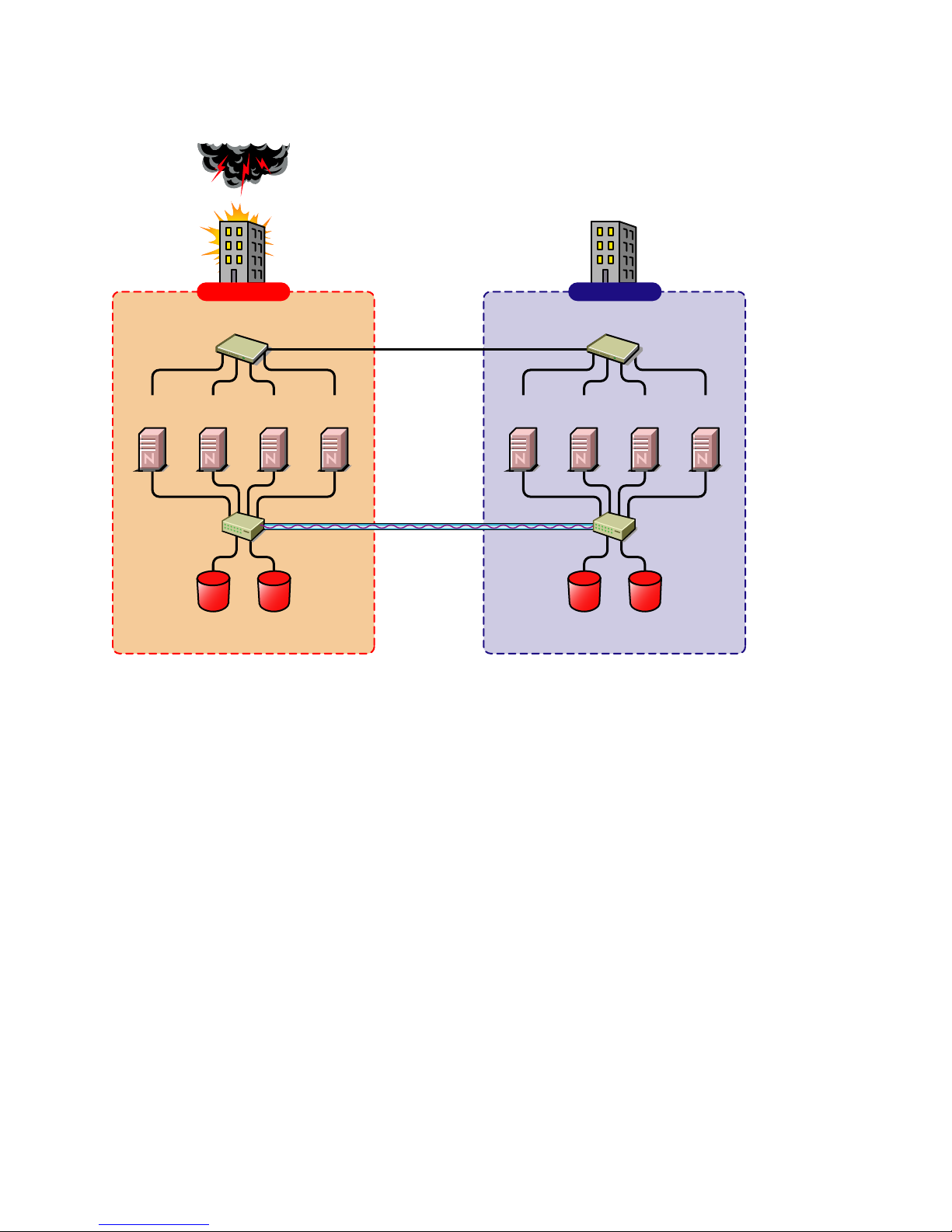
Figure 1-2 Cluster of Clusters
Building A Building B
novdocx (en) 11 December 2007
Two independent clusters at
geographically separate sites
Server
1A
Fibre Channel
Server
Switch
Ethernet Switch
2A
Fibre Channel
Cluster Site 1
Server
3A
Disk Arrays
Server
4A
WAN
eDirectory
DirXML
SAN
Disk blocks
Server
1B
Ethernet Switch
Server2BServer
3B
Fibre Channel
Switch
Fibre Channel
Disk Arrays
Cluster Site 2
Server
4B
Overview 13
Page 14

Implementation Comparison
Table 1-1 Disaster Recovery Implementation Comparison
Stretch Cluster Cluster of Clusters
novdocx (en) 11 December 2007
Advantages It automatically fails over.
It is easier to manage than
separate clusters.
Disadvantages
Failure of site interconnect can
result in LUNs becoming primary
at both locations (split brain
problem) if host-based mirroring
is used.
An SBD partition must be
mirrored between sites.
It accommodates only two sites.
All IP addresses must reside in
the same subnet.
The eDirectory partition must
span the cluster.
The chance of LUNs at both
locations becoming primary is
minimized.
eDirectory partitions don't need
to span the cluster.
Each cluster can be in a
separate eDirectory tree.
IP addresses for each cluster
can be on different IP subnets.
It accommodates more than two
sites and cluster resources can
fail over to separate clusters
(multiple-site fan-out failover
support).
SBD partitions are not mirrored
between sites.
Resource configurations must be
kept in sync manually.
14 Novell Business Continuity Clustering 1.1 for NetWare Administration Guide
Page 15

Stretch Cluster Cluster of Clusters
novdocx (en) 11 December 2007
Other Considerations Host-based mirroring is required
to mirror the SBD partition
between sites.
Link variations can cause false
failovers.
You could consider partitioning
the eDirectory tree to place the
cluster container in a partition
separate from the rest of the
tree.
The cluster heartbeat must be
increased to accommodate link
latency between sites.
You can set this as high as 30
seconds, monitor cluster
heartbeat statistics, and then
tune down as needed.
Because all IP addresses in the
cluster must be on the same
subnet, you must ensure that
your routers handle gratuitous
ARP.
Contact your router vendor or
consult your router
documentation for more
information.
Depending on the platform used,
storage arrays must be
controllable by scripts that run on
NetWare
are not SMI-S compliant.
®
or Linux if the SANs
1.2.2 Novell Business Continuity Clusters
Novell Business Continuity Clusters is a cluster of clusters similar to what is described above,
except that the cluster configuration, maintenance, and synchronization have been automated by
adding specialized software.
Novell Business Continuity Clustering software is an integrated set of tools to automate the setup
and maintenance of a Business Continuity infrastructure. Unlike competitive solutions that attempt
to build stretch clusters, Novell Business Continuity Clustering utilizes a cluster of clusters. Each
site has its own independent clusters, and the clusters in each of the geographically separate sites are
each treated as "nodes" in a larger cluster, allowing a whole site to do fan-out failover to other
multiple sites. Although this can currently be done manually with a cluster of clusters, Novell
Business Continuity Clustering automates the system using eDirectory and policy-based
management of the resources and storage systems.
Novell Business Continuity Clustering software provides the following advantages:
Integrates with SAN hardware devices to automate the failover process using standards based
mechanisms such as SMI-S.
Utilizes Novell Identity Manager technology to automatically synchronize and transfer cluster-
related eDirectory objects from one cluster to another.
Provides the capability to fail over as few as one cluster resource, or as many as all cluster
resources.
Overview 15
Page 16

Includes intelligent failover that lets you do site failover testing as a standard practice.
Provdes scripting capability for enhanced control and customization.
Provides simplified business continuity cluster configuration and management using the
browser-based iManager management tool.
Runs on Linux and NetWare.
1.2.3 Usage Scenarios
There are several Business Continuity Clustering usage scenarios that can be used to achieve the
desired level of disaster recovery. Three possible scenarios include:
A Two-Site Business Continuity Cluster Solution
A Multiple-Site Business Continuity Cluster Solution
A Low-Cost Business Continuity Cluster Solution
Two-Site Business Continuity Cluster Solution
The two-site solution can be used in one of two ways:
novdocx (en) 11 December 2007
A primary site in which all services are normally active, and a secondary site which is
effectively idle, with the data mirrored at it and the applications and services ready to load if
needed.
Two active sites each supporting different applications and services. Either site can take over
for the other site at any time.
The first option is typically used when the purpose of the secondary site is primarily testing by the
IT department. The second option is typically used in a company that has more than one large site of
operations.
16 Novell Business Continuity Clustering 1.1 for NetWare Administration Guide
Page 17

Figure 1-3 Two-Site Business Continuity Cluster
Two independent clusters at
geographically separate sites
Building A Building B
novdocx (en) 11 December 2007
Server
1A
Fibre Channel
Server
Switch
Ethernet Switch
2A
Fibre Channel
Cluster Site 1
Server
3A
Disk Arrays
Server
4A
WAN
eDirectory
DirXML
Server
1B
SAN
Disk blocks
Ethernet Switch
Server2BServer
3B
Fibre Channel
Switch
Fibre Channel
Disk Arrays
Cluster Site 2
Server
4B
Multiple-Site Business Continuity Cluster Solution
This is a large Business Continuity Cluster solution capable of supporting up to 32 nodes per site
and more than two sites. Services and applications can do fan-out failover between sites. Replication
of data blocks is typically done by SAN vendors, but can be done by host-based mirroring for
synchronous replication over short distances. The illustration below depicts a four-site business
continuity cluster.
Overview 17
Page 18

Figure 1-4 Multiple-Site Business Continuity Cluster
novdocx (en) 11 December 2007
Building D
Ethernet Switch
Server2DServer
3C
4B
Fibre Channel
Switch
Fibre Channel
Disk Arrays
Server
4C
Server
3D
Fibre Channel
Switch
4D
Server
1A
Fibre Channel
Switch
Four independent clusters in
geographically separate sites
Building A Building B
Ethernet Switch
Server
Server
2A
Fibre Channel
Disk Arrays
Cluster Site 1
WAN
eDirectory
DirXML
Server
3A
4A
SAN
Disk blocks
Server
Ethernet Switch
Server
Server2BServer
1B
Fibre Channel
Disk Arrays
Cluster Sites 2, 3, and 4
1C
Building C
Ethernet Switch
Server
1D
Server2CServer
Server
3B
Fibre Channel
Switch
Fibre Channel
Disk Arrays
Using the Novell Portal Services, iChain®, and ZENworks® products, all services, applications, and
data can be rendered through the internet, allowing for loss of service at one site but still providing
full access to the services and data by virtue of the ubiquity of the internet. Data and services
continue to be available from the other mirrored sites. Moving applications and services to the
Internet frees corporations from the restrictions of traditional LAN-based applications. Traditional
LAN applications require a LAN infrastructure that must be replicated at each site, and might
require relocation of employees to allow the business to continue. Internet-based applications allow
employees to work from any place that offers an internet connection, including homes and hotels.
Low-Cost Business Continuity Cluster Solution
The low-cost business continuity cluster solution is similar to the previous two solutions, but
replaces Fibre Channel arrays with iSCSI arrays. Data block mirroring can be accomplished either
with iSCSI-based block replication, or host-based mirroring. In either case, snapshot technology can
allow for asynchronous replication over long distances. However, the lower cost solution does not
necessarily have the performance associated with higher-end Fibre Channel storage arrays.
18 Novell Business Continuity Clustering 1.1 for NetWare Administration Guide
Page 19

2
Installation and Setup
This section covers the following information to help you install, set up, and configure Novell®
Business Continuity Clustering for your specific needs:
Section 2.1, “Requirements,” on page 19
Section 2.2, “Installing Identity Manager,” on page 21
Section 2.3, “Installing Novell Business Continuity Cluster Software,” on page 23
Section 2.4, “Configuring File System Mirroring,” on page 25
Section 2.5, “Setting Up Novell Business Continuity Cluster Software,” on page 29
Section 2.6, “Managing a Novell Business Continuity Cluster,” on page 43
Section 2.7, “Business Continuity Cluster Failure Types,” on page 49
2.1 Requirements
novdocx (en) 11 December 2007
2
The requirements in this section must be met prior to installing Novell Business Continuity Cluster
software.
Section 2.1.1, “NetWare 6.5 SP 5 or SP 6 (OES 1 SP2 or SP3 NetWare),” on page 19
Section 2.1.2, “Novell eDirectory 8.8,” on page 20
Section 2.1.3, “Novell Cluster Services 1.8.2 for NetWare,” on page 20
Section 2.1.4, “OpenSLP,” on page 20
Section 2.1.5, “OpenWBEM,” on page 21
Section 2.1.6, “BASH,” on page 21
Section 2.1.7, “LIBC,” on page 21
Section 2.1.8, “autoexec.ncf File,” on page 21
Section 2.1.9, “Shared Disk Systems,” on page 21
Section 2.1.10, “Link Speeds,” on page 21
2.1.1 NetWare 6.5 SP 5 or SP 6 (OES 1 SP2 or SP3 NetWare)
NetWare® 6.5 Support Pack 5 or 6 (same as OES 1 Support Pack 2 or 3 Netware) must be installed
and running on all servers that will be part of a business continuity cluster.
The requires the NetWare 6.5 post Support Pack 5 Update. See TID # 2974185 (http://
support.novell.com/cgi-bin/search/searchtid.cgi?/2974185.htm). If you have installed NetWare 6.5
Support Pack 6, the Support Pack 5 Update is not required.
See the OES NetWare Installation Guide for information on installing and configuring NetWare 6.5.
Installation and Setup
19
Page 20

2.1.2 Novell eDirectory 8.8
eDirectory 8.8 is supported with Business Continuity Clustering 1.1 Support Pack 1. See the
eDirectory 8.8 documentation (http://www.novell.com/documentation/edir88/index.html) for more
information.
2.1.3 Novell Cluster Services 1.8.2 for NetWare
Two to four clusters with Novell Cluster Services™ 1.8.2 (the version that ships with NetWare 6.5
Support Pack 5) or later installed and running on each node in the cluster.
Each cluster must have a unique name, even if the clusters reside in different Novell eDirectory™
trees, and clusters must not have the same name as any of the eDirectory trees in the business
continuity cluster.
See the OES Novell Cluster Services 1.8.2 Administration Guide for NetWare for information on
installing and configuring Novell Cluster Services.
The hardware requirements for Novell Business Continuity Cluster software are the same as for
Novell Cluster Services. For more information, see “Hardware Requirements” and “Shared
Disk System Requirements” in the OES Novell Cluster Services 1.8.2 Administration Guide for
NetWare.
Some SAN vendors require you to purchase or license their CLI (Command Line Interface)
separately. The CLI for the SAN might not initially be included with your hardware.
novdocx (en) 11 December 2007
Also, some SAN hardware may not be SMI-S compliant and can’t be managed using SMI-S
commands.
The recommended configuration is to have each cluster be in the same eDirectory tree. You can have
a business continuity cluster with clusters in separate eDirectory trees. See Appendix A,
“Implementing a Multiple-Tree BCC,” on page 81 for more information.
You must have the nwcs18pt3 or later cluster patch. See TID # 2974985 (http://support.novell.com/
cgi-bin/search/searchtid.cgi?/2974985.htm). This patch can only be applied to NetWare 6.5 Support
Pack 5. If you have upgraded to NetWare 6.5 Support Pack 6, this patch is not required.
The recommended configuration of a business continuity cluster is to have each Novell Cluster
Services cluster be in the same eDirectory tree. You can have a business continuity cluster with
clusters in separate eDirectory trees. See Appendix A, “Implementing a Multiple-Tree BCC,” on
page 81 for more information.
In order to add or change cluster peer credentials, you must access iManager on a server that is in the
same eDirectory tree as the cluster you are adding or changing peer credentials for.
2.1.4 OpenSLP
You must have SLP (Server Location Protocol) set up and configured properly. See Configuring
OpenSLP for eDirectory (http://www.novell.com/documentation/edir873/edir873/data/
aksbdp5.html#aksbdp5) in the Novell eDirectory 8.7.3 Administration Guide.
20 Novell Business Continuity Clustering 1.1 for NetWare Administration Guide
Page 21

2.1.5 OpenWBEM
OpenWBEM must be running and configured to start in autoexec.ncf. See the OpenWBEM
Services Administration Guide for OES (http://www.novell.com/documentation/oes/cimom/data/
front.html#front).
For the required OpenWBEM patch, see TID # 5004180 (http://www.novell.com/support/
search.do?cmd=displayKC&docType=kc&externalId=InfoDocument-patchbuilderreadme5004180&sliceId=&dialogID=34683729&stateId=0%200%2034689728).
2.1.6 BASH
BASH must be installed on all nodes that participate in the BCC. The BASH shell does not need to
be running, only installed.
2.1.7 LIBC
You must have the latest LIBC patch installed. This is currently libcsp6X. See TID # 5003460 (http:/
/www.novell.com/support/search.do?cmd=displayKC&docType=kc&externalId=InfoDocumentpatchbuilder-readme5003460&sliceId=&dialogID=36100275&stateId=0%200%2036102542).
novdocx (en) 11 December 2007
2.1.8 autoexec.ncf File
The sys:\system\autoexec.ncf file must be modified so that the call to sys:/bin/
unixenv.ncf is before the calls to openwbem.ncf and ldbcc.ncf.
2.1.9 Shared Disk Systems
For Business Continuity Clustering 1.1 on NetWare, a shared disk system (Storage Area Network or
SAN) is required for each cluster in the business continuity cluster. See “Shared Disk System
Requirements” in the OES Novell Cluster Services 1.8.2 Administration Guide for NetWare.
2.1.10 Link Speeds
For real-time mirroring, link speeds should be 1 GB or better, the fibre-channel cable length between
sites should be less than 200 kilometers, and the links should be dedicated.
Many factors should be considered for distances greater than 200 kilometers, some of which
include:
The amount of data being transferred
The bandwidth of the link
Whether or not snapshot technology is being used
2.2 Installing Identity Manager
DirXML® is now called Identity Manager (IDM). IDM 2.0.2 is part of the IDM 2 Bundle Edition
(formerly referred to as a starter pack) that is included with OES NetWare and OES Linux Support
Pack 2.
Installation and Setup 21
Page 22

The same installation program used to install the Identity Manager engine is also used to install the
Identity Manager drivers and management utilities. See Installing Identity Manager on NetWare
(http://www.novell.com/documentation/dirxml20/admin/data/abaa2oj.html) in the Novell Nsure
Identity Manager 2.0.1 Administration Guide.
NOTE: The IDM 2.0.1 documentation also applies to IDM 2.0.2.
The Identity Manager (IDM) 2.0.2 engine and eDirectory driver (or later version of IDM 2.x) must
be installed on one node in each cluster. The node where the Identity Manager engine and eDirectory
driver is installed must have an eDirectory replica with at least read/write access to all eDirectory
objects that will be synchronized between clusters (see the list in the Important reminder below).
This does not apply to all eDirectory objects in the tree.
The IDM 2.0.2 management utilities must also be installed, and can be installed on a cluster node,
but installing them on a non-cluster node is the recommended configuration. The management
utilities should be installed on the same server as iManager. See “Business Continuity Cluster
Component Locations” on page 25 for specific information on where to install IDM components.
NOTE: Filtered eDirectory replicas are not supported with this version of Business Continuity
Cluster software. Full replicas are required.
novdocx (en) 11 December 2007
IMPORTANT: The eDirectory replica must have at least read/write access to the following
containers:
The Identity Manager driver set container.
The container where the Cluster object resides.
The container where the Server objects reside.
If server objects reside in multiple containers, this must be a container high enough in the tree
to be above all containers that contain server objects.
Best practice is to have all server objects in one container.
The container where the cluster pool and volume objects will be placed when they are
synchronized to this cluster. This container is referred to as the landing zone. The NCP server
objects for the virtual server of a BCC enabled resource will also be placed in the landing zone.
If the eDirectory replica does not have read/write access to the containers listed above,
synchronization will not work properly.
Installing Identity Manager 3 Bundle Edition
IDM 3.0.1 is supported with BCC 1.1 Support Pack 1 and is included with the IDM 3.0.1 Bundle
Edition. Instructions for installing and configuring the IDM 3.0.1 Bundle Edition can be found with
the IDM 3.0.1 Bundle Edition Documentation (http://www.novell.com/documentation/oes/implgde/
index.html?page=/documentation/oes/implgde/data/b4dgr2g.html#b4dgr2k).
22 Novell Business Continuity Clustering 1.1 for NetWare Administration Guide
Page 23

2.3 Installing Novell Business Continuity Cluster
Software
It is necessary to run the Novell Business Continuity Clustering installation program when you want
to:
Install the Business Continuity Cluster engine software on cluster nodes for the clusters that
will be part of a business continuity cluster.
Install the iManager snap-ins for Business Continuity on either a NetWare 6.5 server or a
Windows server.
When you run the installation program to install the Business Continuity Cluster engine software,
the eDirectory schema is automatically extended in the eDirectory tree where the engine software is
installed.
The Business Continuity Cluster installation installs to only one cluster at a time You must run the
installation program again for each NetWare cluster.
The Business Continuity Cluster installation program is run from a Windows workstation. Prior to
running the installation program, the Windows workstation must have the latest Novell Client™
software installed and you must be authenticated to the eDirectory tree where the cluster resides.
novdocx (en) 11 December 2007
Information for installing BCC 1.1 is contained in the following sections:
Section 2.3.1, “Business Continuity Cluster Licensing,” on page 23
Section 2.3.2, “Running the Business Continuity Cluster Installation Program,” on page 23
Section 2.3.3, “Business Continuity Cluster Component Locations,” on page 25
2.3.1 Business Continuity Cluster Licensing
Novell Business Continuity Cluster software requires a paper license agreement for each business
continuity cluster.
2.3.2 Running the Business Continuity Cluster Installation
Program
To install Novell Business Continuity Clustering, download and copy the software to a directory on
your Windows workstation, then complete the following steps:
1 From the directory on your Windows workstation where you just copied the Business
Continuity Clustering software, run install.exe.
2 Continue through the installation wizard until you get to the page that prompts you to select the
components to install.
3 Select at least one of the Identity Manager templates for iManager installation options and the
Novell Business Continuity Cluster component, then click Next.
Selecting Identity Manager Templates for NetWare iManager Servers installs the templates on
a NetWare server. The templates add functionality to iManager so you can manage your
Business Continuity Cluster. You will be asked to specify the NetWare server where the
templates will be installed later in the installation.
Installation and Setup 23
Page 24

Selecting the Identity Manager Templates for Windows iManager Servers installs the templates
on the local Windows server. You must have iManager installed on the Windows server before
installing the templates. The templates add functionality to iManager so you can manage your
business continuity cluster. You will be asked to specify the path to Tomcat (a default path is
provided) on the Windows server later in the installation.
The Business Continuity Cluster component contains the core software engine files that make
up the Business Continuity Cluster product. The Business Continuity Cluster software must be
installed on all nodes in each cluster that will be part of a Business Continuity Cluster.
4 Do one of the following:
If you chose to install the IDM iManager templates on a NetWare server, specify the name
of the eDirectory tree and the fully distinguished name for the server where you want to
install the templates. Then click Next.
If you don’t know the fully distinguished name for the server, you can browse and select
it.
If you chose to install the IDM iManager templates on a Windows server, specify the path
to Tomcat (a default path is provided) on the server. Then click Next.
You must have iManager installed on the Windows server before installing the templates.
5 Continue through the Upgrade Reminder screen and then specify the name of the eDirectory
tree and the fully distinguished name for the cluster where you want to install the core software
files.
If you don’t know the fully distinguished name for the cluster, you can browse and select it.
novdocx (en) 11 December 2007
6 Select the servers in the cluster where you want to install the core software files for the
Business Continuity Cluster product.
All servers currently in the cluster you specified are listed and are selected by default.
You can choose to automatically start Business Continuity Cluster software on each selected
node after the installation is complete. If Business Continuity Cluster software is not started
automatically after the installation, you can start it manually later by rebooting the cluster
server or by entering LDBCC at the server console.
7 Enter the name and password of an eDirectory user (or browse and select one) with sufficient
rights to manage your BCC. This name should be entered in eDirectory dot format. For
example, admin.servers.novell.
This user should have at least Read and Write rights to the All Attribute Rights property on the
Cluster object of the remote cluster.
8 Continue through the final installation screen and then restart the cluster nodes where IDM is
running and where you have upgraded libc.nlm.
Restarting the cluster nodes can be performed in a rolling fashion in which one server is
restarted while the other servers in the cluster continue running. Then another server is
restarted, and then another, until all servers in the cluster have been restarted.
This lets you keep your cluster up and running and lets your users continue to access the
network while cluster nodes are being restarted.
9 Repeat the above procedure for each cluster that will be part of the business continuity cluster.
24 Novell Business Continuity Clustering 1.1 for NetWare Administration Guide
Page 25

2.3.3 Business Continuity Cluster Component Locations
The following figure illustrates where the various components needed for a business continuity
cluster are installed.
Figure 2-1 Business Continuity Cluster Component Locations
novdocx (en) 11 December 2007
Server
A
IDM
Managment
Utilities
BCC
iManager
plug-ins
Fibre Channel
Ethernet Switch
NW 6.5
iManager
Server
1A
Switch
Fibre Channel
Disk Arrays
Cluster Site 1
Building A
NW 6.5
NCS
BCC eng.
Server
2A
NW 6.5
NCS
BCC eng.
Server
3A
NW 6.5
NCS
BCC eng.
IDM eng.
IDM eDir
Driver
WAN
eDirectory
IDM
SAN
Disk blocks
NW 6.5
NCS
BCC eng.
IDM eng.
IDM eDir
Driver
NW 6.5
NCS
BCC eng.
Server
1B
Building B
Ethernet Switch
Server
2B
NW 6.5
NCS
BCC eng.
Fibre Channel
Disk Arrays
Cluster Site 2
NW 6.5
iManager
Server
Server
B
IDM
Managment
3B
Utilities
BCC
iManager
plug-ins
Fibre Channel
Switch
Figure 2-1 uses the following abbreviations:
BCC eng. -- Business Continuity Cluster engine
NCS -- Novell Cluster Services
IDM eng. -- Identity Manager engine
IDM eDir Driver -- Identity Manager eDirectory Driver
NW 6.5 -- NetWare 6.5
2.4 Configuring File System Mirroring
Several different methods and scenarios for mirroring data between geographically separate sites
exist. Each method has its own strengths and weaknesses. After considering the different methods,
you will need to choose either host-based mirroring or SAN-based mirroring (also called arraybased mirroring) and whether you want the mirroring to be synchronous or asynchronous.
Installation and Setup 25
Page 26

SAN-based synchronous mirroring is preferred and is provided by SAN hardware manufacturers.
Host-based synchronous mirroring functionality is included with the NSS file system (NSS
mirroring) that is part of NetWare 6.5.
NOTE: The Business Continuity Cluster 1.1 product does not perform data mirroring. You must
configure either SAN-based mirroring or host-based mirroring separately.
NSS mirroring is a checkpoint-based synchronous mirroring solution. Data blocks are written
synchronously to multiple storage devices. It is an alternative to SAN array-based synchronous
replication options.
IMPORTANT: NSS Snapshot technology does not work in a business continuity cluster.
Figure 2-2 Synchronous Mirroring
Synchronous
Mirroring
Building A Building B
novdocx (en) 11 December 2007
Ethernet Switch
Server 2
Fibre Channel
Switch
Server 3Server 1 Server 4
Changes
Completion
Fibre Channel
Disk Array
Ethernet Switch
Server 6 Server 7Server 5 Server 8
Fibre Channel
Switch
Fibre Channel
Disk Array
MirrorOriginal
2.4.1 Configuring NSS Mirroring
NSS partitions must be mirrored after they are created. If you have an existing partition that you
want to mirror, you can either create another partition of equal size on another device to mirror the
first partition to, or let the mirroring software automatically create another partition of equal size on
another device.
When you create a Novell Cluster Services system that utilizes shared storage space (a Storage Area
Network or SAN), it is important to remember that all servers attached to the shared device, whether
in the cluster or not, have access to all of the volumes on the shared storage space unless you
specifically prevent such access. Novell Cluster Services arbitrates access to shared volumes for all
cluster nodes, but cannot protect shared volumes from being corrupted by noncluster servers.
26 Novell Business Continuity Clustering 1.1 for NetWare Administration Guide
Page 27

NOTE: Software included with your SAN can be used to mask LUNs or provide zoning capabilities
that will prevent shared volumes from being corrupted by noncluster servers.
Creating and Mirroring NSS Partitions on Shared Storage
Prior to creating and mirroring NSS partitions on shared storage, ensure that you have
All servers in the cluster connected to a shared storage system
One or more drive arrays configured on the shared storage system
The drives on the shared storage system marked as shared.
To create and mirror NSS partitions:
1 Start NSSMU by entering NSSMU at the server console of a cluster server.
2 Select Partitions from the NSSMU main menu.
3 Press the Insert key and select the device on your shared storage system where you want to
create a partition.
With a device marked as sharable for clustering, all partitions on that device are automatically
sharable.
novdocx (en) 11 December 2007
Device names are not changeable and might be labeled something like 0x2 or 0x1.
4 Select NSS as the partition type, then specify the partition size and, if desired, an NSS pool
name and label.
If you specify a pool name, a pool by that name will automatically be created on the partition. If
no pool name is specified, you will have to create a pool on the partition later.
4a If you chose to create a pool, choose whether you want the pool to be activated and cluster
enabled when it is created.
The Activate on Creation feature is enabled by default. This causes the pool to be
activated as soon as it is created. If you choose not to activate the pool, you will have to
manually activate it later before it can be used.
The Cluster Enable on Creation feature is also enabled by default. If you want to cluster
enable the pool at the same time it is created, accept the default entry (Yes) and continue
with Step 4b. If you want to cluster enable the pool at a later date, see the OES Novell
Cluster Services 1.8.2 Administration Guide for NetWare for more information.
4b Specify the Virtual Server Name, IP Address, Advertising Protocols and, if necessary, the
CIFS Server Name.
When you cluster-enable a pool, a virtual Server object is automatically created and given
the name of the Cluster object plus the cluster-enabled pool. For example, if the cluster
name is cluster1 and the cluster-enabled pool name is pool1, then the default virtual server
name will be cluster1_pool1_server. You can edit the field to change the default virtual
server name.
Each cluster-enabled NSS pool requires its own IP address. The IP address is used to
provide access and failover capability to the cluster-enabled pool (virtual server). The IP
address you assign to the pool remains assigned to the pool regardless of which server in
the cluster is hosting the pool.
You can select one or all of the advertising protocols. NCP™ is the protocol used by
Novell clients, CIFS is the protocol used by Microsoft clients, and AFP is the protocol
Installation and Setup 27
Page 28

used by Macintosh* clients. Selecting any of the protocols causes lines to be added to the
pool resource load and unload scripts to activate the selected protocols on the cluster. This
lets you ensure that the cluster-enabled pool you just created is highly available to all your
clients.
If you select CIFS as one of the protocols, a CIFS Server Name is also required. This is the
server name CIFS clients see when they browse the network. A default server name is
listed, but you can change the server name by editing the text in the field.
4c Select Create to create and cluster-enable the pool.
5 Select the partition you want to mirror (this might be the partition you just created) and press
the F3 key.
6 Select the device with free space or the partition you want to mirror to, then select YES to
mirror the partition.
To ensure disaster recovery, the device you select to mirror should be in another storage array
in the other data center.
Creating an NSS Pool and Volumes
After an NSS partition has been created and mirrored, if you have not already done so, you must
create an NSS pool and volume on that partition. To do this, follow the instructions in "“Creating
NSS Pools” " in the “Installation and Setup” section of the Novell Cluster Services 1.8.2
Administration Guide for NetWare.
novdocx (en) 11 December 2007
Novell Cluster Services Configuration and Setup
After configuring NSS mirroring and creating a pool and volume on the mirrored NSS partition, if
you did not cluster-enable the NSS pool on the mirrored partition when you created it, do so by
following the instructions in the “Installation and Setup”section of the Novell Cluster Services 1.8.2
Administration Guide for NetWare.
When you cluster-enable a shared disk pool, the commands to start and stop the pool resource are
automatically added to the resource load and unload scripts.
Checking NSS Volume Mirror Status
After you have configured NSS mirroring with Novell Cluster Services, you should check to ensure
that it is working properly in a cluster environment.
1 Ensure that the volumes on the cluster-enabled pool are mounted on the assigned server by
entering volumes at the server console.
2 Check the mirror status of the mirrored partition by entering mirror status at the server
console of the server where the NSS pool on the mirrored partition is active.
After entering mirror status, you should see a message indicating that mirror status is 100
percent or a message indicating that the mirrored object is fully synchronized.
3 Migrate the pool to another server in the cluster and again check to ensure the volumes on the
pool are mounted by entering volumes at the server console.
4 Check the mirror status of the partition again by entering mirror status at the server
console.
28 Novell Business Continuity Clustering 1.1 for NetWare Administration Guide
Page 29

IMPORTANT: If you create or delete a pool or partition on shared storage that is part of a business
continuity cluster, you must run the cluster scan for new devices command on a server
in each of the other clusters that belong to the business continuity cluster.
2.4.2 Configuring SAN-Based Mirroring
Consult your SAN vendor or SAN vendor documentation for instructions on configuring SANbased mirroring.
2.4.3 LUN Masking
We recommend that you implement LUN masking in your business continuity cluster for data
protection. LUN masking is provided by your SAN vendor.
LUN masking is the ability to exclusively assign each LUN to one or more host connections. With it
you can assign appropriately sized pieces of storage from a common storage pool to various servers.
See your SAN vendor documentation for more information on configuring LUN masking.
novdocx (en) 11 December 2007
2.5 Setting Up Novell Business Continuity
Cluster Software
After you have installed and configured IDM and the Business Continuity Cluster software, and you
have configured file system mirroring, you need to set up Novell Business Continuity Cluster
software. Instructions contained in this section for setting up Novell Business Continuity Cluster
software consists of:
“Configuring Business-Continuity-Specific IDM Drivers” on page 29
“Configuring Clusters for Business Continuity” on page 35
“Configuring Cluster Resources for Business Continuity” on page 41
2.5.1 Configuring Business-Continuity-Specific IDM Drivers
The IDM preconfigured templates for iManager that were installed when you ran the Business
Continuity Cluster (BCC) installation must be configured so you can properly manage your business
continuity cluster. The preconfigured templates include a template for cluster resource
synchronization and a template for User object synchronization. Cluster resource synchronization
must always be configured, even in a single-tree BCC. User object synchronization is necessary
only if you have more than one eDirectory tree in your business continuity cluster. See Appendix A,
“Implementing a Multiple-Tree BCC,” on page 81 for more information.
IMPORTANT: The Identity Manager engine and eDirectory driver must be installed on one node in
each cluster. The node where Identity Manager is installed must have an eDirectory replica with at
least read/write access to all eDirectory objects that will be synchronized between clusters. This
does not apply to all eDirectory objects in the tree.
The eDirectory replica must have at least read/write access to the following containers:
The Identity Manager driver set container.
The container where the Cluster object resides.
Installation and Setup 29
Page 30

The container where the server objects reside.
If server objects reside in multiple containers, this must be a container high enough in the tree
to be above all containers that contain server objects.
Best practice is to have all server objects in one container.
The container where the cluster pool and volume objects will be placed when they are
synchronized to this cluster. This container is referred to as the landing zone. The NCP server
objects for the virtual server of a BCC enabled resource will also be placed in the landing zone.
If the eDirectory replica does not have read/write access to the containers listed above,
synchronization will not work properly.
NOTE: Filtered eDirectory replicas are not supported with this version of Business Continuity
Cluster software. Full replicas are required.
To configure the IDM drivers/templates:
1 Start your Internet browser and enter the URL for iManager.
novdocx (en) 11 December 2007
The URL is http://server_ip_address/nps/iManager.html. Replace server_ip_address with the
IP address or DNS name of the NetWare server that has iManager and the DirXML
preconfigured templates for iManager installed.
2 Enter your username and password.
3 In the left column, click DirXML Utilities, then click the New Driver link.
4 Choose to place the new driver in a new driver set, then click Next.
Both the User Object Synchronization Driver and the Cluster Resource Synchronization Driver
can be added to the same driver set.
5 Specify the driver set name, context, and the server that the driver set will be associated with.
The server is the same server where you installed the IDM engine and eDirectory driver.
6 Choose to not create a new partition for the driver set, then click Next.
7 Choose to import a preconfigured driver from the server, select the DirXML preconfigured
template for cluster resource synchronization, then click Next.
The template name is BCCClusterResourceSyncronization.XML.
8 Fill in the values on the wizard page as prompted, then click Next.
Each field contains an example of the type of information that should go into the field.
Descriptions of the information required are also included with each field.
Additional information for the wizard page fields includes:
Driver name: Specify a unique name for this driver that will identify its function. For
example, Cluster1SyncCluster2. If you use both preconfigured templates, you must
specify different driver names for each driver template.
Name of SSL Certificate: If you do not have an SSL certificate, leave this value set to the
default. The certificate will be created later in the configuration process. See Step 1 on
page 32 for instructions on creating SSL certificates.
DNS name of other IDM node: Specify the DNS name or IP address of the IDM server
in the other cluster.
30 Novell Business Continuity Clustering 1.1 for NetWare Administration Guide
Page 31

Port number for this driver: If you have a business continuity cluster that consists of
three or four clusters, you must specify unique port numbers for each driver template set.
The default port number is 2002.
You must specify the same port number for the same template in the other cluster. For
example, if you specify 2003 as the port number for the resource synchronization
template, you must specify 2003 as the port number for the resource synchronization
template in the peer driver for the other cluster.
Full Distinguished Name (DN) of the cluster this driver services: For example,
Cluster1.siteA.Novell.
Fully Distinguished Name (DN) of the landing zone container: Specify the context of
the container where the cluster pool and volume objects in the other cluster will be placed
when they are synchronized to this cluster. This container is referred to as the landing
zone. The NCP server objects for the virtual server of a BCC enabled resource will also be
placed in the landing zone.
IMPORTANT: The context must already exist and must be specified using dot format
without the tree name. For example, siteA.Novell.
Prior to performing this step, you could create a separate container in eDirectory specificly
for these cluster pool and volume objects. You would then specify the context of the new
container in this step.
The IDM Driver object must have sufficient rights to create, modify, and delete objects and
attributes in the following containers:
novdocx (en) 11 December 2007
The Identity Manager driver set container.
The container where the Cluster object resides.
The container where the Server objects reside.
If server objects reside in multiple containers, this must be a container high enough in the
tree to be above all containers that contain server objects.
Best practice is to have all server objects in one container.
The container where the cluster pool and volume objects will be placed when they are
synchronized to this cluster.
This container is referred to as the landing zone. The NCP server objects for the virtual
server of a BCC enabled resource will also be placed in the landing zone.
You can do this by making the IDM Driver object security equivalent to another user object
with those rights. See Step 9 on page 31.
If you choose to include User object synchronization, exclude the Admin User object from
being synchronized. See Step 7 on page 83.
9 Make the IDM Driver object security equivalent to an existing User object.
9a Click Define Security Equivalences, then click Add.
9b Browse to and select the desired User object, then click OK.
9c Click Next, then click Finish.
10 Repeat Step 1 through Step 9 above on the other clusters in your business continuity cluster.
This includes creating a new driver and driver set for each cluster.
Installation and Setup 31
Page 32

IMPORTANT: If you have upgraded to IDM 3 and click either the cluster synchronization driver or
the user synchronization driver, a message will be displayed prompting you to convert the driver to a
new architecture. Click OK to convert the driver.
Creating SSL Certificates
It is recommended that you create an an SSL certificate for the Cluster Resource Synchronization
Driver. Creating one certificate creates that certificate for a driver pair. For example, creating an SSL
certificate for the Cluster Resource Synchronization Driver creates the certificate for the Cluster
Resource Synchronization Drivers on both clusters.
To create an SSL certificate:
1 Start your Internet browser and enter the URL for iManager.
The URL is http://server_ip_address/nps/iManager.html. Replace server_ip_address with the
IP address or DNS name of the server that has iManager and the IDM preconfigured templates
for iManager installed.
2 Enter your username and password.
novdocx (en) 11 December 2007
3 In the left column, click DirXML Utilities, then click NDS-to-NDS Driver Certificates.
4 Specify the requested driver information for this cluster, then click Next.
You must specify the driver name (including the context) you supplied in Step 8 on page 30 for
this cluster. Use the following format when specifying the driver name:
DriverName.DriverSet.OrganizationalUnit.OrganizationName
Ensure that there are no spaces (beginning or end) in the specified context, and do not use the
following format:
cn=DriverName.ou=OrganizationalUnitName.o=OrganizationName
5 Specify the requested driver information for the driver in the other cluster, then click Next and
then Finish.
Use the same format specified in Step 4 above.
Synchronizing IDM Drivers
After creating BCC-specific IDM drivers and SSL certificates, if you are adding a new cluster to an
existing business continuity cluster, you must synchronize the BCC-specific IDM drivers. If BCCspecific IDM drivers are not synchronized, clusters can't be enabled for business continuity. This is
not necessary unless you are adding a new cluster to an existing business continuity cluster.
To synchronize BCC-specific IDM drivers:
1 Start your Internet browser and enter the URL for iManager.
The URL is http://server_ip_address/nps/iManager.html. Replace server_ip_address with the
IP address or DNS name of the server that has iManager and the IDM preconfigured templates
for iManager installed.
2 Enter your username and password.
3 In the left column, click DirXML, then click the DirXML Overview link.
4 Search for and find the BCC driver set.
32 Novell Business Continuity Clustering 1.1 for NetWare Administration Guide
Page 33

5 Click the red Cluster Sync icon for the driver you want to synchronize, then click the Migrate
from eDirectory button.
6 Click Add, browse to and select the cluster object for the new cluster you are adding, then click
OK.
Selecting the cluster object will cause the BCC-specific cluster IDM drivers to synchronize.
If you have multiple eDirectory trees in your BCC, see Section A.4, “Synchronizing IDM Drivers,”
on page 83.
Preventing IDM Synchronization Loops
If you have three or more clusters in your business continuity cluster, you should set up IDM user
object and cluster resource object synchronization in a manner that prevents IDM synchronization
loops. IDM synchronization loops can cause excessive network traffic and slow server
communication and performance.
For example, in a three-cluster business continuity cluster, an IDM synchronization loop occurs
when Cluster One is configured to synchronize with Cluster Two, Cluster Two is configured to
synchronize with Cluster Three, and Cluster Three is configured to synchronize back to Cluster One.
This is illustrated in Figure 2-3 below.
novdocx (en) 11 December 2007
Figure 2-3 Three-Cluster IDM Synchronization Loop
Cluster
One
DirXML Sync
DirXML Sync
DirXML Sync
Cluster
Three
Cluster
Tw o
A preferred method is to make Cluster One an IDM synchronization master in which Cluster One
synchronizes with cluster two and Cluster Two and Cluster Three both synchronize with Cluster
One. This is illustrated in Figure 2-4 below.
Installation and Setup 33
Page 34

Figure 2-4 Three-Cluster IDM Synchronization Master
Cluster
One
DirXML Sync
DirXML Sync
novdocx (en) 11 December 2007
Cluster
Three
Cluster
Tw o
You could also have Cluster One synchronize with Cluster Two, Cluster Two synchronize with
Cluster Three, and Cluster Three synchronize back to Cluster Two as is illustrated in Figure 2-5
below.
Figure 2-5 Alternate Three-Cluster IDM Synchronization Scenario
Cluster
One
DirXML Sync
DirXML Sync
Cluster
Three
Cluster
Tw o
To change your BCC synchronization scenario:
1 In the Connections section of the Business Continuity Cluster Properties page, select one or
more peer clusters that you want a cluster to synchronize to, then click Edit.
In order for a cluster to appear in the list of possible peer clusters, that cluster must:
Have Business Continuity Cluster software installed.
Have IDM installed.
Have business continuity-specific IDM drivers configured and running.
Be enabled for business continuity.
34 Novell Business Continuity Clustering 1.1 for NetWare Administration Guide
Page 35

2.5.2 Configuring Clusters for Business Continuity
This procedure consists of
“Enabling Clusters for Business Continuity” on page 35
“Adding Cluster Peer Credentials” on page 35
“Adding Resource Script Search and Replace Values” on page 36
These tasks must be performed on each separate cluster that you want to be part of the business
continuity cluster.
NOTE: Identity Manager must be configured and running before configuring clusters for business
continuity.
Enabling Clusters for Business Continuity
If you want to enable a cluster to fail over selected resources or all cluster resources to another
cluster, you must enable business continuity on that cluster.
novdocx (en) 11 December 2007
1 Start your Internet browser and enter the URL for iManager.
The URL is http://server_ip_address/nps/iManager.html. Replace server_ip_address with the
IP address or DNS name of the server that has iManager and the IDM preconfigured templates
for iManager installed. This server should be in the same eDirectory tree as the cluster you are
enabling for business continuity.
2 Enter your username and password.
3 Ensure that the Business Continuity-specific IDM drivers are running.
3a In the left column, click DirXML, and then click the DirXML Overview link.
3b Search the eDirectory Container or tree for the Business Continuity-specific DirXML
drivers.
3c Click the upper right corner of the driver icon(s) to see if the driver is started or stopped.
If the driver is stopped, you can start it by choosing Start.
4 In the left column, click Clusters, then click the Cluster Options link.
5 Specify a cluster name or browse and select one.
6 Click the Properties button, then click the Business Continuity tab.
7 Ensure that the Enable Business Continuity Features check box is selected.
8 Repeat Step 1 through Step 7 for the other cluster that this cluster will migrate resources to.
9 Continue with Step 1 in the Adding Cluster Peer Credentials section below.
Adding Cluster Peer Credentials
In order for one cluster to connect to a second cluster, the first cluster must be able to authenticate to
the second cluster. To make this possible, you must add the username and password of the user that
the selected cluster will use to connect to the selected peer cluster.
Installation and Setup 35
Page 36

IMPORTANT: In order to add or change cluster peer credentials, you must access iManager on a
server that is in the same eDirectory tree as the cluster you are adding or changing peer credentials
for.
1 In the Connections section of the Business Continuity Cluster Properties page, select the peer
cluster, then click Edit.
In order for a cluster to appear in the list of possible peer clusters, that cluster must
Have Business Continuity Cluster software installed.
Have Identity Manager installed and running.
Have business-continuity-specific Identity Manager drivers configured and running.
Be enabled for business continuity.
2 Add the administrator username and password that the selected cluster will use to connect to
the selected peer cluster.
When adding the administrator username, do not include the context for the user. For example,
bccadmin could be used instead of something like bccadmin.prv.novell.
novdocx (en) 11 December 2007
NOTE: Rather than using the Admin user to administer your BCC, you should consider
creating another user with sufficient rights to the appropriate contexts in your eDirectory tree to
manage your BCC.
3 Repeat Step 1 and Step 2 for the other cluster that this cluster will migrate resources to.
4 Continue with Step 1 in the Adding Resource Script Search and Replace Values section below.
Adding Resource Script Search and Replace Values
To enable a resource for business continuity, certain values (such as IP addresses) specified in
resource load and unload scripts need to be changed in corresponding resources in the other clusters.
You need to add the search and replace strings that are used to transform cluster resource load and
unload scripts from this cluster to another cluster.
TIP: You can see the IP addresses that are currently assigned to resources by entering the display
secondary ipaddress command at the NetWare server console of cluster servers.
The search and replace data is cluster specific, and it is not synchronized via Identity Manager
between the clusters in the business continuity cluster.
To add resource script search and replace values:
1 In the Resource Script Replacements section of the Business Continuity Cluster Properties
page, click New.
2 Add the desired search and replace values, then click OK.
The search and replace values you specify here apply to all resources in the cluster that have
been enabled for business continuity.
For example, if you specified 10.1.1.1 as the search value and 192.168.1.1 as the replace value,
the resource with the 10.1.1.1 IP address in its scripts would be searched for in the primary
cluster and, if found, the 192.168.1.1 IP address would be assigned to the corresponding
resource in the secondary cluster.
36 Novell Business Continuity Clustering 1.1 for NetWare Administration Guide
Page 37

You can also specify global search and replace addresses for multiple resources in one line.
This can be used only if the last digits in the IP addresses are the same in both clusters. For
example, if you specify 10.1.1. as the search value and 192.168.1. as the replace value, the
software finds the 10.1.1.1, 10.1.1.2, 10.1.1.3 and 10.1.1.4 addresses and then replaces them
with the 192.168.1.1, 192.168.1.2, 192.168.1.3, and 192.168.1.4 addresses, respectively.
NOTE: It is important in the above example that a trailing dot be used in the search and replace
value. If a trailing dot is not used, 10.1.1 could be replaced with an IP value such as
192.168.100 instead of 192.168.1.
You can check the Use Regular Expressions check box to use wildcard characters in your search and
replace values. The following links provide information on regular expressions and wildcard
characters:
Regular Expressions (http://www.opengroup.org/onlinepubs/007908799/xbd/re.html)
Regular-Expressions.info (http://www.regular-expressions.info/)
Wikipedia (http://en.wikipedia.org/wiki/Regular_expression)
oreilly.com (http://www.oreilly.com/catalog/regex/)
novdocx (en) 11 December 2007
You can find additional information on regular expressions and wildcard characters by searching the
Web.
Adding SAN Management Configuration Information
You can create scripts and add commands that are specific to your SAN hardware. These scripts and
commands might be needed to promote mirrored LUNs to primary on the cluster where the pool
resource is being migrated to, or demote mirrored LUNs to secondary on the cluster where the pool
resource is being migrated from.
You can also add Perl scripts and add commands to scripts to call other scripts. Any command that
can be run at the NetWare server console can be used. The scripts or commands you add are stored
in eDirectory. If you add commands to call outside scripts, those scripts must exist on every server in
the cluster.
To add SAN management configuration information:
1 Start your Internet browser and enter the URL for iManager.
The URL is http://server_ip_address/nps/iManager.html. Replace server_ip_address with the
IP address or DNS name of the server that has iManager and the IDM preconfigured templates
for iManager installed.
2 Enter your username and password.
3 In the left column, click Clusters, then click the Cluster Options link.
4 Specify a cluster name or browse and select one.
5 Under Cluster Objects, select a BCC-enabled resource, then click Details.
BCC-enabled resources have the BCC label on the resource type icon.
6 Click the Business Continuity tab, then click SAN Management.
7 Create BCC SAN management load and unload scripts.
7a Under BCC Load Scripts, click New to bring up a page that lets you create a script to
promote mirrored LUNs on a cluster.
Installation and Setup 37
Page 38

You can also delete a script, edit a script by clicking Details, or change the order that load
scripts execute by clicking the Move Up and Move Down links.
7b Fill in the values on the SAN Management Script Details page, click Apply and then OK,
and then click OK on the Resource Properties page.
NOTE: After clicking Apply and OK on the Script Details page, you are returned to the
Resource Properties page (with the Business Continuity tab selected) If you do not click
OK on the Resource Properties page, your script changes will not be saved.
Descriptions of the information required for the page fields and options include:
Name and Description: Specify a name, and if desired, a description of the script
you are creating.
CIMOM IP/DNS: If you are not using a template and checked the CIM Client check
box in the previous screen, specify the IP address or DNS name for your SAN. This
is the IP address or DNS name that is used for SAN management.
Namespace: If you checked the CIM Client check box in the previous screen, accept
the default namespace, or specify a different namespace for your SAN.
Namespace determines which models and classes are used with your SAN. Consult
your SAN documentation to determine which namespace is required for your SAN.
Username and Password: If you checked the CIM Client check box in the previous
screen, specify the username and password that is used to connect to and manage
your SAN.
Port: If you checked the CIM Client check box in the previous screen, accept the
default port number or specify a different port number. This is the port number that
CIMOM (your SAN manager) uses. Consult your SAN documentation to determine
which port number you should use.
novdocx (en) 11 December 2007
Secure: If you checked the CIM Client check box in the previous screen, check or
uncheck the Secure check box depending whether you want SAN management
communication to be secure (http or https).
Script Parameters: Script parameters let you specify variables and values for those
variables that are used in the SAN management script.
To specify a variable, click New and then provide the variable name and value in the
fields provided. Click OK to save your entries. You can specify additional variables
by clicking New again and providing variable names and values. You can also edit
and delete existing script parameters by clicking the applicable link.
Script Parameters Text Box: You can use the text box to add script commands to
the script you are creating.
These script commands are specific to your SAN hardware. You can add a Perl script,
or any commands that can be run on Linux or NetWare (depending on your
platform). If you add commands to call outside scripts, those scripts must exist on
every server in the cluster.
CIM Enabled: You can check this box if your SAN supports SMI-S and you did not
check the CIM Client checkbox on the previous screen. This will cause the CIMspecific fields to become active on this screen.
Synchronous: If this check box is left unchecked, multiple scripts can be run
concurrently. Checking the box causes scripts to run individually, one after another.
Most SAN vendors do not support running multiple scripts concurrently.
38 Novell Business Continuity Clustering 1.1 for NetWare Administration Guide
Page 39

Edit Flags: This is an advanced feature, and should not be used except under the
direction of Novell Technical Support.
IMPORTANT: The CIMOM daemons on all nodes in the BCC should be configured to bind to all
IP addresses on the server.
BCC connects to the CIMOM using the master IP address for the cluster. Because the master IP
address moves to other nodes during a failover or migration, the CIMOM must be configured to
bind to all IP addresses (secondary and primary), rather than just the primary IP address of the host.
You can do this by editing the openwbem.conf file. See Changing the OpenWBEM CIMOM
Configuration (http://www.novell.com/documentation/oes/cimom/data/bv3wn7m.html#bv3wn7m)
in the OpenWBEM Services Administration Guide for OES for more information.
Assigning BCC Administrative User Trustee Rights
You must ensure that the user who will manage your BCC (BCC admistrative user) is a trustee of the
cluster objects and has at least read and write eDirectory rights to the All Attributes Rights property.
You must also ensure that the BCC administrative user has file system rights to the
_ADMIN:\Novell\Cluster directory of all nodes in your BCC. This is necessary because
the_ADMIN volume is virtual, and is created each time the server starts. For this reason, you can’t
assign eDirectory trustee rights to the _Admin volume.
novdocx (en) 11 December 2007
To assign BCC administrative user eDirectory trustee rights:
1 Start your Internet browser and enter the URL for iManager.
The URL is http://server_ip_address/nps/iManager.html. Replace server_ip_address with the
IP address or DNS name of the NetWare server that has iManager and the Identity Manager
preconfigured templates for iManager installed.
2 Enter your username and password.
3 In the left column, click Rights, then click the Modify Trustees link.
4 Specify the cluster object name or browse and select it, then click OK.
5 If the BCC administrative user is not listed as a trustee, click the Add Trustee button, browse
and select the user object, then click OK.
6 Click Assigned Rights for the BCC administrative user, then ensure that the Read and Write
check boxes are selected for the All Attributes Rights property.
7 Click Done to save your changes.
8 Repeat Step 3 through Step 7 for the other cluster objects in your BCC.
You must also ensure that the BCC administrative user has Read, Write, Create, Erase, Modify, and
File Scan access rights to the sys:/tmp directory on every node in your clusters.
NOTE: If you are concerned about denial of service attacks with the BCC administrative user, you
can set a quota of 5 MB for that user. This would prevent the BCC administrative user from filling
the sys: volume by copying an excessive number of files to the sys:/tmp directory
Installation and Setup 39
Page 40

To assign BCC administrative user file system rights to the _ADMIN:\Novell\Cluster
directory:
1 Open the sys:/etc/trustrees.xml file
2 Add a trustee entry for the BCC Administrative user that assigns Read, Write, Modify, and File
Scan (RWMF) rights to the _ADMIN:\Novell\Cluster directory.
3 Repeat this process on all NetWare nodes that are part or your BCC.
The trustee entry could be similar to the following entry:
<addTrustee>
<name>BCCAdmin.users.lab.acme_tree</name>
<fileName>_ADMIN:\Novell\Cluster</fileName>
<rights>
<read/>
<write/>
<fileScan/>
<modify/>
</rights>
</addTrustee>
Note the following items with this example:
The <name> element is the BCC administrative user. The tree name is required.
novdocx (en) 11 December 2007
The <filename> element must be _ADMIN:\Novell\Cluster
The rights must be RWMF.
You must add the trustee entry to all the NetWare nodes in your BCC.
The following is an example of a complete trustees.xml file. Note the multiple trustee
entries. For this reason you should edit this file and add the BCC entry rather than copy the file
from server to server.
<specialTrustees>
<addTrustee>
<name>BCCAdmin.users.lab.acme_tree</name>
<fileName>_ADMIN:\Novell\Cluster</fileName>
<rights>
<read/>
<write/>
<fileScan/>
<modify/>
</rights>
</addTrustee>
<addTrustee>
<context />
<name>[public]</name>
<fileName>_admin:manage_nss\files.cmd</fileName>
<rights>
<read />
<write />
<fileScan />
</rights>
<background />
</addTrustee>
</specialTrustees>
40 Novell Business Continuity Clustering 1.1 for NetWare Administration Guide
Page 41

After the trustees.xml file has been modified on all NetWare nodes, the NetWare nodes
must be rebooted. This can be done in a rolling fashion. You should start with the node that has
the highest IP address first and work down in IP address order. This will speed the rate at which
the NCS master node acquires the change.
2.5.3 Configuring Cluster Resources for Business Continuity
Cluster resources can be configured for business continuity either at the same time they are created
or after they are created. Configuring a resource for business continuity consists of enabling that
resource for business continuity, adding load and unload script search and replace data specific to
the resource, and selecting peer clusters for the resource.
IMPORTANT: In a business continuity cluster, you should have only one NSS pool for each LUN
that could be failed over to another cluster. This is necessary because in a business continuity cluster,
entire LUNs fail over to other clusters, rather than individual pools, which fail over to other nodes
within a cluster.
A cluster-enabled NSS pool must contain at least one volume before it can be enabled for BCC. You
will get an error message if you attempt to BCC-enable an NSS pool that does not contain a volume.
novdocx (en) 11 December 2007
Also, if you have encrypted NSS volumes in your BCC, then all clusters in that BCC MUST be in
the same eDirectory tree. If not, then the clusters in the other eDirectory tree will not be able to
decrypt the NSS volumes. This rule applies to both NetWare and Linux BCCs
Enabling a Cluster Resource for Business Continuity
Cluster resources must be enabled for business continuity on the primary cluster before they can be
synchronized and appear as resources in the other clusters in the business continuity cluster.
Enabling a cluster resource makes it possible for that cluster resource or cluster pool resource to be
migrated to another cluster.
IMPORTANT: Although you can add search and replace data that is resource-specific after you
enable a resource for business continuity, we recommend adding the search and replace data for the
entire cluster before you enable resources for business continuity. See “Adding Resource Script
Search and Replace Values” on page 36 for instructions on adding search and replace data for the
entire cluster.
When you enable a resource for business continuity and that resource has been synchronized and
appears in the other clusters, the preferred nodes for the other clusters will by default be set to all
nodes in the cluster. If you want to change the resource’s preferred nodes for other clusters in your
BCC, you must manually do it. Changes to the preferred nodes list in the primary cluster do not
automatically replicate to the preferred nodes lists for other clusters in your BCC.
1 (Conditional) If you are creating a new cluster resource or cluster pool resource, follow the
instructions for creating a cluster resource or cluster pool resource using iManager in the OES
Novell Cluster Services 1.8.2 Administration Guide for NetWare, then continue with Step 3
below.
If you have Business Continuity Clustering software installed and configured, at the end of the
resource creation process, the wizard for creating a cluster resource will display a page for
enabling the resource for business continuity.
Installation and Setup 41
Page 42

2 (Conditional) If you are enabling an existing cluster resource or cluster pool resource for
business continuity, do the following:
2a Start your Internet browser and enter the URL for iManager.
The URL is http://server_ip_address/nps/iManager.html. Replace server_ip_address with
the IP address or DNS name of the server that has iManager and the IDM preconfigured
templates for iManager installed.
2b Enter your username and password.
2c In the left column, click Clusters, then click the Cluster Options link.
2d Specify a cluster name or browse and select one.
2e Select the desired cluster resource from the list of Cluster objects
2f Click the Details link, then click the Business Continuity tab.
3 Ensure that the Enable Business Continuity Features check box is selected.
4 Continue with Step 1 in the Adding Resource Script Search and Replace Values section.
Adding Resource Script Search and Replace Values
novdocx (en) 11 December 2007
If you did not previously add search and replace data specific to the entire cluster, you must now add
it for this resource.
IMPORTANT: Adding resource script search and replace values for the entire cluster is
recommended rather than adding those values for individual cluster resources. You should contact
Novell Technical Support prior to adding search and replace values for individual cluster resources.
To enable a resource for business continuity, certain values (such as IP addresses, DNS names, and
tree names) specified in resource load and unload scripts need to be changed in corresponding
resources in the other clusters. You need to add the search and replace strings that are used to
transform cluster resource load and unload scripts from this cluster to another cluster.
The search and replace data you add is resource specific, and it is not synchronized via IDM
between the clusters in the business continuity cluster.
To add resource script search and replace values specific to this resource:
1 In the Resource Replacement Script section of the page, click New.
If a resource has already been configured for business continuity, you can click Edit to change
existing search and replace values or click Delete to delete them.
2 Add the desired search and replace values, then click OK.
The search and replace values you specify here apply to only to the resource you are enabling
for business continuity. If you want the search and replace values to apply to any or all cluster
resources, add them to the entire cluster instead of just to a specific resource.
See “Adding Resource Script Search and Replace Values” on page 36 for more information on
resource script search and replace values and adding those values to the entire cluster.
3 If this is an existing cluster resource, continue with Step 1 in the Selecting Peer Clusters for the
Resource section below. If you are creating a new cluster resource, click Next, then continue
with Select the other clusters that this resource can be migrated to. in the Selecting Peer
Clusters for the Resource section below.
42 Novell Business Continuity Clustering 1.1 for NetWare Administration Guide
Page 43

You can check the Use Regular Expressions check box to use wildcard characters in your search and
replace values. The following links provide information on regular expressions and wildcard
characters:
Regular Expressions (http://www.opengroup.org/onlinepubs/007908799/xbd/re.html)
Regular-Expressions.info (http://www.regular-expressions.info/)
Wikipedia (http://en.wikipedia.org/wiki/Regular_expression)
oreilly.com (http://www.oreilly.com/catalog/regex/)
You can find additional information on regular expressions and wildcard characters by searching the
Web.
IMPORTANT: If you change the resource-specific search and replace data after initially adding it,
you must update the resource load and unload script in one of the other clusters by editing it and
adding a space or a comment to it. This will cause the script to be updated with the new search and
replace data.
You could also update the IP address on the cluster protocols page in iManager to cause IP address
search and replace values to be updated for both load and unload scripts. This might require you to
go back and change the IP addresses specified in the resource load and unload scripts in the source
cluster to their original values.
novdocx (en) 11 December 2007
Selecting Peer Clusters for the Resource
Peer clusters are the other clusters that this cluster resource can be migrated to. The cluster or
clusters that you select determine where the resource can be manually migrated. If you decide to
migrate this resource to another cluster, you must migrate it to one of the clusters that have been
selected.
1 Select the other clusters that this resource can be migrated to.
2 Do one of the following:
If you are creating a new nonpool resource, click Finish.
If this is an existing cluster resource, click Apply.
If you are creating a new cluster pool resource, click Next and continue with the Adding
Disk Array Mapping Information section below.
If this is an existing cluster pool resource, continue with the Adding Disk Array Mapping
Information section below.
Adding Disk Array Mapping Information
For information on adding disk array mapping information, see “Adding SAN Management
Configuration Information” on page 37.
2.6 Managing a Novell Business Continuity
Cluster
After you have installed, set up, and configured Novell Business Continuity Cluster software and
resources, some additional information can be useful to help you effectively manage your business
continuity cluster. This information consists of instructions for migrating resources from one cluster
Installation and Setup 43
Page 44

to another, changing existing cluster peer credentials, and generating a business continuity report
that provides cluster configuration and status information.
See the following sections for this additional information:
Section 2.6.1, “Migrating a Cluster Resource to Another Cluster,” on page 44
Section 2.6.2, “Changing Cluster Peer Credentials,” on page 45
Section 2.6.3, “Viewing the Current Status of a Business Continuity Cluster,” on page 46
Section 2.6.4, “Generating a Cluster Report,” on page 46
Section 2.6.5, “Disabling Business Continuity Cluster Resources,” on page 47
Section 2.6.6, “Business Continuity Cluster Console Commands,” on page 47
2.6.1 Migrating a Cluster Resource to Another Cluster
Although there is now an automatic failover feature for Novell Business Continuity Clustering, it is
recommended that you manually migrate resources from one cluster to another cluster. See
Appendix B, “Setting Up Auto-Failover,” on page 87. If the node where a resource is running fails,
if the entire cluster fails, or if you just want to migrate the resource to another cluster, you can
manually start the cluster resource on another cluster in the business continuity cluster. If the source
cluster site fails, you will have to go to the destination cluster site to manually migrate or bring up
resources at that site. Each resource will start on its preferred node on the destination cluster.
novdocx (en) 11 December 2007
TIP: You can use the cluster migrate command to start resources on nodes other than the
preferred node on the destination cluster.
To manually migrate cluster resources from one cluster to another:
1 Start your Internet browser and enter the URL for iManager.
The URL is http://server_ip_address/nps/iManager.html. Replace server_ip_address with the
IP address or DNS name of the server that has iManager and the IDM preconfigured templates
for iManager installed.
2 Enter your username and password.
3 In the left column, click Clusters, then click the BCC Manager link.
4 Specify a cluster name or browse and select one.
5 Select one or more cluster resources, then click BCC Migrate.
6 Select the cluster where you want to migrate the selected resources, then click OK.
The resources will migrate to their preferred node on the destination cluster. If you select Any
Configured Peer as the destination cluster, the business continuity cluster software will choose
a destination cluster for you. The destination cluster that is chosen is the first cluster that is up
in the peer clusters list for this resource.
Migrating a pool resource to another cluster causes the following to happen:
1. If the source cluster can be contacted, the state of the resource is changed to offline.
2. The resource changes from primary to secondary on the source cluster.
3. Any SAN script that is associated with the pool resource is run.
44 Novell Business Continuity Clustering 1.1 for NetWare Administration Guide
Page 45

4. On the destination cluster, the resource changes from secondary to primary so that it can be
brought online.
A custom Perl script can be created for disk mapping on fibre channel SANs. The purpose of
this script is to make the LUNs in the SAN available to the destination cluster. A reverse script
is also created for testing purposes so pool resources can be migrated back to the source cluster.
5. The cluster scan for new devices command is executed on the destination cluster
so that the cluster is aware of LUNs that are now available.
6. Resources are brought online and load on the their most preferred node in the cluster.
7. Resources appear as running and primary on the cluster where you have migrated them.
WARNING: Do not migrate resources for a test failover if the peer (LAN) connection between the
source and destination cluster is down. Possible disk problems and data corruption could occur. This
warning does not apply if resources are migrated during an actual cluster site failure.
2.6.2 Changing Cluster Peer Credentials
Changing cluster peer credentials consists of changing the username and password for the
administrative user that the selected cluster will use to connect to a selected peer cluster. You might
need to do this if the administrator username or password changes for any clusters in the business
continuity cluster.
novdocx (en) 11 December 2007
1 Start your Internet browser and enter the URL for iManager.
The URL is http://server_ip_address/nps/iManager.html. Replace server_ip_address with the
IP address or DNS name of the NetWare server that has iManager and the IDM preconfigured
templates for iManager installed.
IMPORTANT: In order to add or change cluster peer credentials, you must access iManager
on a server that is in the same eDirectory tree as the cluster you are adding or changing peer
credentials for.
2 Enter your username and password.
3 In the left column, click Cluster Administration, then click the Management link.
4 Specify a cluster name or browse and select one.
5 Click Connections and select a peer cluster.
6 Edit the administrator username and password that the selected cluster will use to connect to
the selected peer cluster, then click OK.
When specifying a username, you don’t need to include the Novell eDirectory context for the
user name.
NOTE: If you have a multiple eDirectory tree BCC, and you specify a common username and
password, each eDirectory tree in the business continuity cluster must have the same username
and password.
Installation and Setup 45
Page 46

2.6.3 Viewing the Current Status of a Business Continuity
Cluster
You can view the current status of your business continuity cluster by using either iManager or the
server console of a cluster in the business continuity cluster.
Using iManager
1 Start your Internet browser and enter the URL for iManager.
The URL is http://server_ip_address/nps/iManager.html. Replace server_ip_address with the
IP address or DNS name of the server that has iManager and the IDM preconfigured templates
for iManager installed.
2 Enter your username and password.
3 In the left column, click Clusters, then click the BCC Manager link.
4 Specify a cluster name or browse and select one.
Using this page, you can see if all cluster peer connections are up or if one or more peer connections
are down. You can also see the status of the BCC resources in the business continuity cluster.
novdocx (en) 11 December 2007
Using the Server Console
At the server console of a server in the business continuity cluster, enter the following commands to
get different kinds of status information:
cluster view
cluster status
cluster connections
2.6.4 Generating a Cluster Report
You can generate a report for each cluster in the business continuity cluster to list information on a
specific cluster, such as current cluster configuration, cluster nodes, and cluster resources. You can
print or save the report using your browser.
1 Start your Internet browser and enter the URL for iManager.
The URL is http://server_ip_address/nps/iManager.html. Replace server_ip_address with the
IP address or DNS name of the server that has iManager and the IDM preconfigured templates
for iManager installed.
2 Enter your username and password.
3 In the left column, click Clusters, then click the Cluster Manager link.
4 Specify a cluster name or browse and select one.
5 Click the Run Report button.
46 Novell Business Continuity Clustering 1.1 for NetWare Administration Guide
Page 47

2.6.5 Disabling Business Continuity Cluster Resources
After enabling a resource for business continuity, it is possible to disable it. You might want to do
this if you accidentally enabled the resource for business continuity, or if you no longer want a
specific resource to potentially run on another cluster.
If you enabled a cluster resource for business continuity and you want to disable it, do the following:
1 Start your Internet browser and enter the URL for iManager.
The URL is http://server_ip_address/nps/iManager.html. Replace server_ip_address with the
IP address or DNS name of the server that has iManager and the IDM preconfigured templates
for iManager installed.
2 Enter your username and password.
3 In the left column, click Clusters, then click the Cluster Options link.
4 Specify the cluster name or browse and select it.
5 Select the desired cluster resource from the list of Cluster objects
6 Click the Details link, then click the Business Continuity tab.
7 Uncheck the Enable Business Continuity Features check box, then click Apply.
8 Wait for IDM to synchronize the changes.
novdocx (en) 11 December 2007
This could take from 30 seconds to one minute, depending on your configuration.
9 Delete the cluster resource object on the clusters where you no longer want the resource to run.
IMPORTANT: If you disable BCC for a cluster using either iManager or the Cluster Disable
console command, BCC will also be disabled for those cluster resources that have been BCCenabled. If you re-enable BCC for the cluster, you must re-enable each individual cluster resource
that you want to be BCC-enabled.
This can be a time-consuming process if you have many BCC-enabled cluster resources. For this
reason, you should use caution when disabling BCC for an entire cluster.
2.6.6 Business Continuity Cluster Console Commands
Novell Business Continuity Cluster (BCC) Services provides some server console commands to
help you perform certain business continuity cluster-related tasks. Some of the commands can be
used both with Novell Cluster Services and with Novell Business Continuity Clustering. The
following table lists the BCC-related server console commands and gives a brief description of each
command. For other cluster console commands, see “Novell Cluster Services Console Commands”
in the OES Novell Cluster Services 1.8.2 Administration Guide for NetWare.
To execute a cluster console command, enter cluster followed by the command. For example, if
this cluster is a member of a business continuity cluster, and you want to see this cluster's peer
clusters, enter cluster view at the server console. You can also enter cluster help at the
console prompt to get information on the commands and their functions.
Installation and Setup 47
Page 48

BCC Console Commands Description
CLUSTER CREDENTIALS {cluster} Lets you change the administrator username and
password that this cluster will use to connect to the
specified peer cluster. The cluster you specify must
be a member of a cluster that has already been
enabled for Business Continuity Clustering.
CLUSTER DISABLE {resource} Disables Business Continuity Clustering for the
specified resource. The resource you specify must be
a member of a cluster that has already been enabled
for Business Continuity Clustering. If no resource is
specified, the entire cluster is disabled for Business
Continuity Clustering.
If you disable BCC for a cluster using the Cluster
Disable console command, BCC will also be disabled
for those cluster resources that have been BCCenabled. If you re-enable BCC for the cluster, you
must re-enable each individual cluster resource that
you want to be BCC-enabled.
novdocx (en) 11 December 2007
This can be a time-consuming process if you have
many BCC-enabled cluster resources. For this
reason, you should use caution when disabling BCC
for an entire cluster.
CLUSTER ENABLE {resource} Enables Business Continuity Clustering for the
specified resource. The resource you specify must be
a member of a cluster that has already been enabled
for Business Continuity Clustering. If no resource is
specified, the entire cluster is enabled for Business
Continuity Clustering.
When BCC-enabling a resource, previous versions of
the CLI would not set the peer clusters where the
resource was assigned to run. The only way to set
peer clusters for a resource was through iManager.
The new version of the cluster CLI automatically sets
all the clusters in the BCC on a resource. Assigning a
resource to specific clusters still must be done
through iManager.
CLUSTER MIGRATE {source/resource}
{destination/node name}
Migrates the specified resource from the specified
source cluster to the specified target (destination)
cluster. Specifying * for the resource name will
migrate all BCC-enabled resources. Specifying * for
the node name will bring the resource online at the
most preferred node.
48 Novell Business Continuity Clustering 1.1 for NetWare Administration Guide
Page 49

BCC Console Commands Description
CLUSTER RESETRESOURCES Changes the state of all resources on this cluster to
offline and secondary. This is a recovery procedure
that should be run when a cluster in a BCC is brought
back into service.
You should run this command when only one node is
a member of the cluster.
1. After a failure, bring up one node in the cluster.
All other nodes should remain powered off.
2. Run the cluster resetresources
command.
3. Bring up the remaining nodes in the cluster.
CLUSTER VIEW Displays the node name, cluster epoch number,
master node name, a list of nodes that are currently
members of the cluster, and peer clusters if this
cluster is a member of a Business Continuity Cluster.
novdocx (en) 11 December 2007
CLUSTER RESOURCES {resource} Lets you view the state and location of cluster
resources and whether resources are primary or
secondary. You can optionally specify a specific
resource name.
CLUSTER STATUS Lets you view the state and location of cluster
resources and whether resources are primary or
secondary. If the resource state is primary, the node
where the resource is running is displayed. If the
resource state is secondary, the cluster where the
resource is located is displayed.
CLUSTER CONNECTIONS {-a} Displays the connection status of the cluster.
Specifying -a will attempt to show the connection
status of all clusters in the BCC.
CLUSTER REFRESH This command should not be used except under the
direction of Novell Technical Services.
2.7 Business Continuity Cluster Failure Types
There are several failure types associated with a business continuity cluster that you should be aware
of. Understanding the failure types and knowing how to respond to each can help you more quickly
recover a cluster. Some of the failure types and responses differ depending on whether you have
implemented SAN-based mirroring or host-based mirroring. Promoting or demoting LUNs is
sometimes necessary when responding to certain types of failures.
NOTE: The terms promote and demote are used here in describing the process of changing LUNs to
a state of primary or secondary, but your SAN vendor documentation might use different terms such
as mask and unmask.
Installation and Setup 49
Page 50

2.7.1 SAN-based Mirroring Failure Types and Responses
SAN-based mirroring failure types and responses are described in the following sections:
“Primary Cluster Fails but Primary SAN Does Not” on page 50
“Primary Cluster and Primary SAN Both Fail” on page 50
“Secondary Cluster Fails but Secondary SAN Does Not” on page 50
“Secondary Cluster and Secondary SAN Both Fail” on page 50
“Primary SAN Fails but Primary Cluster Does Not” on page 51
“Secondary SAN Fails but Secondary Cluster Does Not” on page 51
“Intersite SAN Connectivity Is Lost” on page 51
“Intersite LAN Connectivity Is Lost” on page 51
Primary Cluster Fails but Primary SAN Does Not
This type of failure can be temporary (transient) or long-term. There should be an initial response
and then a long-term response based on whether the failure is transient or long-term. The initial
response is to restore the cluster to normal operations. The long-term response is total recovery from
the failure.
novdocx (en) 11 December 2007
Promote the secondary LUN to primary. Cluster resources load (and become primary on the second
cluster). If the former primary SAN has not been demoted to secondary, you might need to demote it
manually. The former primary SAN must be demoted to secondary before bringing cluster servers
back up. Consult your SAN hardware documentation for instructions on demoting and promoting
SANs. You can use the cluster resetresources console command to change resource
states to offline and secondary. See the cluster resetresources command.
Prior to bringing up the cluster servers, the administrator must ensure that the SAN is in a state in
which the cluster resources cannot come online and cause a divergence in data. Divergence in data
occurs when connectivity between SANs has been lost and both clusters assert that they have
ownership of their respective disks.
Primary Cluster and Primary SAN Both Fail
Bring the primary SAN back up and follow your SAN vendor’s instructions to remirror and, if
necessary, promote the former primary SAN back to primary. Then bring up the former primary
cluster servers and fail back the cluster resources.
Secondary Cluster Fails but Secondary SAN Does Not
No additional response is necessary for this failure other than recovering the secondary cluster.
When you bring the secondary cluster back up, the LUNs will still be in a secondary state to the
primary SAN.
Secondary Cluster and Secondary SAN Both Fail
Bring the secondary SAN back up and follow your SAN vendor's instructions to remirror. When you
bring the secondary cluster back up, the LUNs will still be in a secondary state to the primary SAN.
50 Novell Business Continuity Clustering 1.1 for NetWare Administration Guide
Page 51

Primary SAN Fails but Primary Cluster Does Not
When the primary SAN fails, the primary cluster will also fail. Bring the primary SAN back up and
follow your SAN vendor’s instructions to remirror and, if necessary promote the former primary
SAN back to primary. You might need to demote the LUNs and resources to secondary on the
primary SAN before bringing them back up. You can use the cluster resetresources
console command to change resource states to offline and secondary. See the cluster resetresources
command. Bring up the former primary cluster servers and fail back resources.
Secondary SAN Fails but Secondary Cluster Does Not
When the secondary SAN fails, the secondary cluster will also fail. Bring the secondary SAN back
up and follow your SAN vendor’s instructions to remirror. Then bring the secondary cluster back up.
When you bring the secondary SAN and cluster back up, resources will still be in a secondary state.
Intersite SAN Connectivity Is Lost
Recover your SANs first, then remirror from the good side to the bad side.
Intersite LAN Connectivity Is Lost
novdocx (en) 11 December 2007
Users might not be able to access servers in the primary cluster but can possibly access servers in the
secondary cluster. If both clusters are up, nothing additional is required. An error will be displayed.
Wait for connectivity to resume.
If you have configured the automatic failover feature, see Appendix B, “Setting Up Auto-Failover,”
on page 87.
2.7.2 Host-Based Mirroring Failure Types and Responses
Primary Cluster Fails but Primary SAN Does Not
Response for this failure is the same as for SAN-based mirroring described above. Do not disable
MSAP, which is enabled by default.
Primary Cluster and Primary SAN Both Fail
Bring up your primary SAN or iSCSI target before bringing up your cluster servers. Then run the
Cluster Scan For New Devices command from a secondary cluster server. Ensure
remirroring completes before bringing downed cluster servers back up.
Additional response is the same as for SAN-based mirroring described above.
Secondary Cluster Fails but Secondary SAN Does Not
Response for this failure is the same as for SAN-based mirroring described above.
Secondary Cluster and Secondary SAN Both Fail
Bring up your secondary SAN or iSCSI target before bringing up your cluster servers. Then run the
Cluster Scan For New Devices command on a primary cluster server to ensure that
remirroring takes place.
Installation and Setup 51
Page 52

Additional response is the same as for SAN-based mirroring described above.
Primary SAN Fails but Primary Cluster Does Not
If your primary SAN fails, all nodes in your primary cluster will also fail. Bring up your primary
SAN or iSCSI target and then bring up your cluster servers. Then run the Cluster Scan For
New Devices command from a secondary cluster server. Ensure remirroring completes before
bringing downed cluster servers back up.
Additional response is the same as for SAN-based mirroring described above.
Secondary SAN Fails but Secondary Cluster Does Not
Bring up your secondary SAN or iSCSI target before bringing up your cluster servers. Then run the
Cluster Scan For New Devices command on a primary cluster server to ensure
remirroring takes place.
Additional response is the same as for SAN-based mirroring described above.
Intersite SAN Connectivity is Lost
novdocx (en) 11 December 2007
You must run the Cluster Scan For New Devices command on both clusters to ensure
remirroring takes place. Additional response is the same as for SAN-based mirroring described
above.
Intersite LAN Connectivity is Lost
Response for this failure is the same as for SAN-based mirroring described above.
52 Novell Business Continuity Clustering 1.1 for NetWare Administration Guide
Page 53

3
Upgrading BCC
BCC 1.0 supports only Novell® Cluster ServicesTM for NetWare®. This section covers two upgrade
scenarios:
Section 3.1, “Upgrading BCC 1.0 to BCC 1.1 for NetWare,” on page 53
Section 3.2, “Upgrading BCC 1.0 to BCC 1.1 for Linux,” on page 55
3.1 Upgrading BCC 1.0 to BCC 1.1 for NetWare
To upgrade from BCC 1.0 to BCC 1.1 for NetWare you need to
1. Upgrade NetWare and apply the latest patches on the cluster servers in each cluster.
2. Install Identity Manager (IDM) 2 Bundle Edition on one server in each cluster.
3. Install BCC 1.1 on all nodes where BCC 1.0 is installed.
novdocx (en) 11 December 2007
3
4. Reset credentials for the BCC Administrative user.
5. Authorize the BCC Administrative user.
6. Verify SAN scripts.
7. Delete and re-create BCC-specific IDM drivers.
3.1.1 Upgrading NetWare
NetWare must be upgraded on each BCC cluster server to NetWare 6.5 Support Pack 5 (same as
OES NetWare Support Pack 2), which is the minimum requirement for BCC 1.1. See Section 2.1,
“Requirements,” on page 19 for more information on what is required for BCC 1.1. See Upgrading
to OES NetWare (http://www.novell.com/documentation/oes/install-nw/data/
hqwoj1yu.html#hqwoj1yu) for more information on upgrading NetWare.
In addition to upgrading NetWare, you must also apply the latest NetWare and Cluster Services
patches to the upgraded servers. See the BCC 1.1 Readme file (http://www.novell.com/
documentation/bcc11/readme/data/readme.html) for instructions on the necessary patches.
Performing a Rolling Cluster Upgrade
Performing a rolling upgrade to NetWare 6.5 Support Pack 5 (SP 5) and applying the latest patches
lets you keep your cluster up and running and lets your users continue to access the network while
the upgrade is being performed.
During a rolling cluster upgrade, one server is upgraded to NetWare 6.5 SP 5 and the latest patches
are applied while the other servers in the cluster continue running a previous support pack of
NetWare 6.5. Then another server is upgraded to NetWare 6.5 SP 5 with the latest patches, and then
another, until all servers in the cluster have been upgraded to NetWare 6.5 SP 5 with the latest
patches.
After upgrading NetWare and applying the latest patches, reboot the server to automatcially load
Cluster Services software.
Upgrading BCC
53
Page 54

During the upgrade process, cluster pools, volumes, and resources will fail over from the server
being upgraded to other servers in the cluster. After a cluster server is upgraded and brought back
online, the pools, volumes, and resources that failed over to other servers during the upgrade process
fail back to the upgraded server.
3.1.2 Installing or Upgrading IDM
You must upgrade to or install IDM 2 Bundle Edition on one cluster server in each cluster of your
BCC. If you are upgrading to IDM on a BCC server where DirXML is installed, see Upgrading
(http://www.novell.com/documentation/dirxml20/admin/data/ampxjxi.html) and Common
Installation Scenarios (http://www.novell.com/documentation/dirxml20/admin/data/
brpgxw9.html#brpgxw9) in the IDM 2.0.1 Administration Guide.
If you are installing IDM 2 Bundle Edition, see Section 2.2, “Installing Identity Manager,” on
page 21.
3.1.3 Installing BCC 1.1
After upgrading NetWare and IDM, you must install BCC 1.1 on all cluster nodes that will be part of
your BCC. See Section 2.3, “Installing Novell Business Continuity Cluster Software,” on page 23
for information on installing BCC 1.1.
novdocx (en) 11 December 2007
The BCC 1.1 installation program autodetects if BCC 1.0 is installed and performs the necessary
updates to convert BCC 1.0 to BCC 1.1. This includes searching eDirectory
updating those scripts to be SMI-S compliant.
TM
for SAN scripts and
3.1.4 Resetting BCC Administrative User Credentials
The BCC Administrative user credentials that were set for BCC 1.0 do not work with BCC 1.1. A
fully distinguished eDirectory name (FDN) was required for BCC 1.0, but BCC 1.1 requires only
the BCC administrator name. For instructions on resetting BCC Administrative user credentials, see
Section 2.6.2, “Changing Cluster Peer Credentials,” on page 45.
3.1.5 Authorizing the BCC Administrative User
The BCC admistrative user must be a trustee of the cluster objects in your BCC, and have at least
read and write rights to the all attributes rights property.
1 Start your Internet browser and enter the URL for iManager.
The URL is http://server_ip_address/nps/iManager.html. Replace server_ip_address with the
IP address or DNS name of the NetWare server that has iManager and the IDM preconfigured
templates for iManager installed.
2 Enter your username and password.
3 In the left column, click Rights, then click the Modify Trustees link.
4 Specify the cluster object name or browse and select it, then click OK.
5 If the BCC Administrative user is not listed as a trustee, click the Add Trustee button, browse
and select the user object, then click OK.
6 Click Assigned Rights for the BCC administrative user, then ensure that the Read and Write
check boxes are selected for the All Attributes Rights property.
54 Novell Business Continuity Clustering 1.1 for NetWare Administration Guide
Page 55

7 Click Done to save your changes.
8 Repeat Step 3 through Step 7 for the other cluster objects in your BCC.
3.1.6 Verifying SAN Scripts
The BCC 1.1 installation program searches for and updates any SAN scripts that you created for
BCC 1.0. The updates are performed to make the SAN scripts SMI-S compliant. You should check
all SAN scripts after installing BCC 1.1 to ensure that they will perform the desired functions.
3.1.7 Deleting and Re-Creating BCC IDM Drivers
After completing the upgrade procedures in the above sections you must delete the BCC IDM
drivers that were created when you installed and configured BCC 1.0. This includes the cluster
synchronization driver(s), and if you configured User object synchronization, the User object
synchronization driver. You must then re-create those drivers in order for them to work with BCC
1.1. See Section 2.5.1, “Configuring Business-Continuity-Specific IDM Drivers,” on page 29.
During a BCC upgrade, BCC 1.0 clusters will be unable to communicate with BCC 1.1 clusters.
This condition exists temporarily until the upgrade has been completed. If an actual disaster were to
occur during the upgrade, a BCC 1.0 cluster can be failed over to a BCC 1.1 cluster.
novdocx (en) 11 December 2007
3.2 Upgrading BCC 1.0 to BCC 1.1 for Linux
To upgrade from BCC 1.0 (NetWare only) to BCC 1.1 for Linux, you must first upgrade all nodes in
BCC 1.0 clusters to BCC 1.1 for NetWare. To do this, follow the instructions in Section 3.1,
“Upgrading BCC 1.0 to BCC 1.1 for NetWare,” on page 53.
IMPORTANT: All cluster nodes in every cluster in your BCC must be upgraded to BCC 1.1 for
NetWare before converting clusters to Novell Cluster Services for Linux.
On one cluster upgrade NetWare cluster nodes to Linux by following the instructions in Converting
a NetWare Cluster to Linux (http://www.novell.com/documentation/oes/cluster_admin_lx/data/
bu1b1x8.html) in the OES Novell Cluster Services 1.8.2 Administration Guide for Linux.
Clusters containing NetWare and Linux servers are only supported in a BCC as a temporary means
to convert a cluster from NetWare to Linux. Part of the temporary conversion state includes a
restriction that only one mixed cluster can exist in your BCC. For example, Cluster A can have both
NetWare and Linux nodes, but Cluster B cannot. All nodes in Cluster B must be either NetWare or
Linux.
You must re-create the BCC IDM drivers after converting to Linux. See “Configuring Business-
Continuity-Specific IDM Drivers” in the Novell Business Continuity Clustering for Linux
Adminitration Guide.
Normally, when converting a NetWare cluster to Linux, you need to run the cluster convert
command after the entire cluster has been converted to Linux. When converting a BCC to Linux, do
not run the cluster convert command until all clusters in the BCC have been upgraded and
converted to Linux. See “Finalizing the Cluster Conversion” in the Novell Business Continuity
Clustering for Linux Adminitration Guide.
Upgrading BCC 55
Page 56

The same restrictions that apply to migrating or failing over resources between nodes within a mixed
cluster also apply to migrating or failing over resources between clusters in a mixed BCC. You can
only migrate or fail over NSS pool/volume resources between clusters in a mixed BCC.
novdocx (en) 11 December 2007
56 Novell Business Continuity Clustering 1.1 for NetWare Administration Guide
Page 57

4
Troubleshooting BCC 1.1
This section contains the following topics to help you troubleshoot Novell® Business Continuity
Clustering (BCC) 1.1.
Section 4.1, “Cluster Connection States,” on page 57
Section 4.2, “Driver Ports,” on page 59
Section 4.3, “Excluded Users,” on page 59
Section 4.4, “Security Equivalent User,” on page 60
Section 4.5, “Certificates,” on page 61
Section 4.6, “Clusters Can’t Communicate,” on page 61
Section 4.7, “BCC Startup Flags,” on page 62
Section 4.8, “Problems With BCC Installation on NetWare,” on page 62
Section 4.9, “IDM Drivers for Cluster Synchronization Do Not Start,” on page 63
Section 4.10, “IDM Drivers Do Not Synchronize Objects from One Cluster to Another,” on
page 63
Section 4.11, “Tracing IDM,” on page 64
Section 4.12, “Peer Cluster Communication Not Working,” on page 65
novdocx (en) 11 December 2007
4
Section 4.13, “Administration of Peer Clusters Not Functional,” on page 65
Section 4.14, “Resource Does Not Migrate to Another Cluster,” on page 65
Section 4.15, “Resource Cannot Be Brought Online,” on page 65
Section 4.16, “Dumping Syslog on NetWare,” on page 66
Section 4.17, “Slow Failovers,” on page 66
Section 4.18, “Resource Script Search and Replace Functions Do Not Work,” on page 66
Section 4.19, “Virtual NCP Server IP Addresses Won’t Change,” on page 66
Section 4.20, “IP Address, Virtual Server DN, or Pool Name Does Not Appear on the iManager
Cluster Configuration Page,” on page 67
Section 4.21, “Blank Error String iManager Error Appears While Bringing a Resource Online,”
on page 68
Section 4.22, “Best Practices,” on page 68
Section 4.23, “Mapping Drives in Login Scripts,” on page 68
Section 4.24, “Mapping Drives to Home Directories Using the %HOME_DIRECTORY
Variable,” on page 69
Section 4.25, “BCC Error Codes,” on page 70
4.1 Cluster Connection States
The following table identifies the different cluster connection states and gives descriptions and
possible actions for each state.
Troubleshooting BCC 1.1
57
Page 58

Table 4-1 BCC Connection States
BCC Connection State Number Description Possible Actions
novdocx (en) 11 December 2007
Normal 0 The connections between
clusters are functioning
normally.
Authenticating 1 BCC is in the process of
authenticating to a peer
cluster.
Invalid Credentials 2 You entered the wrong
username and/or password
for the selected peer cluster.
Cannot Connect 3 This cluster cannot connect
to the selected peer cluster.
None required.
Wait until the authentication process
is finished.
Enter the correct username and
password that this cluster will use to
connect to the selected peer cluster.
Ping the peer cluster to see if it is up
and reachable.
Ensure that BCC is running on the
peer cluster and that Novell Cluster
Services
in the peer cluster.
Ensure that OPENWBEM is running
on the peer cluster.
Ensure that a firewall is not
preventing access on OPENWBEM
ports 5988 and 5989.
Ensure that the Admin file system is
running. To do this you can see if the
_admin volume is mounted on
NetWare, or on Linux enter etc/
init.d/adminfs status.
TM
is running on the servers
Not Authorized 4 The connected user does not
have sufficient rights for
permissions.
Connection Unknown 5 The connection state
between clusters is
unknown.
Assign the appropriate trustee rights
to the user who will manage your
BCC.
This connection state might be
caused by any number of problems,
including a severed cable or link
problems between geographic sites.
The connection state numbers are recorded in a log file that you can use to view connection and
status changes for BCC.
The default path to the log file on Linux is /var/log/messages. The administrator might have
changed this path from the default. You can search for BCCD to view BCC related messages and
entries in the log file.
®
To view the log file on NetWare
:
1 Enter log +copy syslog.
2 Using an editor, open the file that is referenced in the message that appears.
58 Novell Business Continuity Clustering 1.1 for NetWare Administration Guide
Page 59

You can get additional information on how to use the log file by entering help log at the
NetWare server console.
4.2 Driver Ports
If your IDM driver or drivers won’t start, check for a port number conflict. IDM driver port numbers
must not conflict (be the same) with other driver port numbers in the cluster or ports being used by
other services (Apache, etc.).
To check driver port numbers:
1 Start your Internet browser and enter the URL for iManager.
The URL is http://server_ip_address/nps/iManager.html. Replace server_ip_address with the
IP address or DNS name of the NetWare server that has iManager and the IDM preconfigured
templates for iManager installed.
2 Enter your username and password.
3 In the left column, click DirXML, then click the DirXML Overview link.
4 Select Search Entire Tree, then click Search.
novdocx (en) 11 December 2007
5 Select the driver you want to check by clicking the red Cluster Sync icon or the blue User Sync
icon.
6 Click the red or blue icon again, then click the DirXML tab (if it is not already selected).
7 In the Authentication context field, view and if necessary change the port numbers next to the
IP address.
For example, the Authentication context field might contain a value similar to
123.12.23.12:2003:2003. In this example, the first port number (2003) is the port number for
the corresponding IDM driver on the cluster this cluster is synchronizing with. The second port
number (2003) is the port number for the IDM driver on this cluster.
These port numbers should be the same, but should not conflict (be the same) as the port
numbers for other IDM drivers on either this or the remote cluster.
8 If you change the port numbers, restart the driver by clicking the upper right corner of the
Cluster Sync or User Sync icon (whichever you have chosen), then click Restart driver.
9 If you changed the port number in Step 7 above, change the port numbers to be the same for the
corresponding driver in the other cluster.
You can do this by repeating Step 1 through Step 8 for the IDM driver on the other cluster.
4.3 Excluded Users
If certain users do not synchronize between clusters, it is possible that those users are included in the
excluded users list.
NOTE: The eDirectory Admin user should never be synchronized between clusters.
To see the excluded users list:
1 Start your Internet browser and enter the URL for iManager.
Troubleshooting BCC 1.1 59
Page 60

The URL is http://server_ip_address/nps/iManager.html. Replace server_ip_address with the
IP address or DNS name of the NetWare server that has iManager and the IDM preconfigured
templates for iManager installed.
2 Enter your username and password.
3 In the left column, click DirXML, then click the DirXML Overview link.
4 Select Search Entire Tree, then click Search.
5 Select the user synchronization driver you want to check by clicking the blue User Sync icon.
This is not necessary for the cluster synchronization driver.
6 Click the blue icon again, then click the DirXML tab if it is not already selected.
7 Click Excluded Users, and view, add, or remove users as desired.
4.4 Security Equivalent User
If resources or peers don’t appear in other clusters in your BCC, it is possible that either a cluster or
user synchronization driver is not security equivalent to a user with administrative rights to the
cluster.
novdocx (en) 11 December 2007
NOTE: Rather than using the eDirectory Admin user to administer your BCC, you should consider
creating another user with sufficient rights to the appropriate contexts in your eDirectory tree to
manage your BCC.
The IDM Driver object must have sufficient rights to create, modify, and delete objects and
attributes in the following containers:
The Identity Manager driver set container.
The container where the Cluster object resides.
The container where the Server objects reside.
If server objects reside in multiple containers, this must be a container high enough in the tree
to be above all containers that contain server objects.
Best practice is to have all server objects in one container.
The container where the cluster pool and volume objects will be placed when they are
synchronized to this cluster. This container is sometimes referred to as the landing zone. The
NCP server objects for the virtual server of a BCC enabled resource will also be placed in the
landing zone.
To make the Cluster and/or User synchronization driver security equivalent to a user with
administrative rights:
1 Start your Internet browser and enter the URL for iManager.
The URL is http://server_ip_address/nps/iManager.html. Replace server_ip_address with the
IP address or DNS name of the NetWare server that has iManager and the IDM preconfigured
templates for iManager installed.
2 Enter your username and password.
3 In the left column, click DirXML, then click the DirXML Overview link.
4 Choose Search Entire Tree, then click Search.
60 Novell Business Continuity Clustering 1.1 for NetWare Administration Guide
Page 61

5 Select the driver you want to check by clicking the red Cluster Sync icon or the blue User Sync
icon.
6 Click the red or blue icon again, then click the DirXML tab if it is not already selected.
7 Click Security Equals, and view or add a security equivalent user as needed.
8 Repeat Step 5 through Step 7 for the other drivers in your BCC.
You must also ensure that the BCC Administrative user has Read, Write, Create, Erase, Modify, and
File Scan access rights to the sys:/tmp directory on every node in your NetWare clusters.
For Linux, ensure that the BCC Administrative user is a LUM-enabled user. To LUM-enable a user,
see Managing User and Group Objects in eDirectory (http://www.novell.com/documentation/oes/
lumadgd/data/aeucqum.html) in the Novell Linux User Management Technology Guide.
NOTE: For NetWare, if you are concerned about denial of service attacks with the BCC
Administrative user, you can set a quota of 5 MB for that user. This can prevent the BCC
Administrative user from filling the sys: volume by copying an excessive number of files to the
sys:/tmp directory
novdocx (en) 11 December 2007
4.5 Certificates
If SSL certificates are not present or have not been created, IDM drivers might not start or function
properly. Novell recommends using SSL certificates for encryption and security.
NOTE: You should create or use a different certificate than the default (dummy) certificate (BCC
Cluster Sync KMO) that is included with BCC.
See “Creating SSL Certificates” on page 32 for more information on creating SSL certificates for
BCC.
4.6 Clusters Can’t Communicate
If the clusters in your BCC can’t communicate with each other, it is possible that the user object you
are using to administer your BCC does not have sufficient rights to the cluster objects for each
cluster. To resolve this problem, ensure that the BCC admistrative user is a trustee of the cluster
objects and has at least read and write rights to the all attributes rights property.
1 Start your Internet browser and enter the URL for iManager.
The URL is http://server_ip_address/nps/iManager.html. Replace server_ip_address with the
IP address or DNS name of the NetWare server that has iManager and the IDM preconfigured
templates for iManager installed.
2 Enter your username and password.
3 In the left column, click Rights, then click the Modify Trustees link.
4 Specify the cluster object name or browse and select it, then click OK.
5 If the BCC Administrative user is not listed as a trustee, click the Add Trustee button, browse
and select the user object, then click OK.
6 Click Assigned Rights for the BCC administrative user, and then ensure the Read and Write
check boxes are selected for the All Attributes Rights property.
Troubleshooting BCC 1.1 61
Page 62

7 Click Done to save your changes.
8 Repeat Step 3 through Step 7 for the other cluster objects in your BCC.
4.7 BCC Startup Flags
There are three optional flags that can be used by BCC during startup. The table below lists the flags
and provides a description of each flag.
Table 4-2 Optional Startup Flags
Startup Flag Description
d On Linux, this flag keeps the bccd from forking (keeps the process in foreground) and log
messages are printed to the running terminal screen (stdout) along with the normal
syslog.
This flag is not used on NetWare.
v On both Linux and NetWare, this flag turns on more verbose logging.
novdocx (en) 11 December 2007
t On both Linux and NetWare, this flag turns on tracing. With tracing turned on, certain
sections of code that fail will report a message containing the condition that failed along
with a file and line number in the code indicating where the condition failed. This is
helpful for reporting problems to Novell Technical Support.
4.7.1 Using BCC Startup Flags
NetWare
On NetWare, edit the sys:\system\ldbcc.ncf file and change the load bccd.nlm line to
load bccd.nlm -flags. Replace flags with any combination of v and/or t. This could include
v, vt, t, or tv.
Linux
On Linux, there are two options:
To use the v and t flags, edit the /etc/init.d/novell-bcc file and change the
NOVELL_BCCD_ARGS= line to NOVELL_BCCD_ARGS=-flags. Replace flags with any
combination of v and/or t. This could include v, vt, t, or tv.
Do not use the d flag with this option.
Stop BCC by entering rcnovell-bccd stop at the server console, then restart it by
entering /opt/novell/bcc/sbin/bccd -flags. Replace flags with any combination
of v, t, and/or d.
4.8 Problems With BCC Installation on NetWare
Occasional problems might exist when installing BCC software on NetWare cluster servers. For
example, you might experience problems expanding an Organizational Unit (OU) when browsing
the eDirectory tree during the BCC installation.
62 Novell Business Continuity Clustering 1.1 for NetWare Administration Guide
Page 63

To resolve this and similar problems, rename the c:\program files\common
files\novell directory on the Windows machine where the installation is being run and restart
the BCC 1.1 installation program.
4.9 IDM Drivers for Cluster Synchronization Do
Not Start
If the IDM drivers for cluster synchronization will not start, the problem may be caused by one of
the following conditions:
A certificate has not been created.
The ports used by the driver are not unique and available.
Each eDirectory driver must listen on a different port number. To specify the port number,
access the driver properties in iManager and specify the appropriate port number in the IP
address field. See Section 2.5.1, “Configuring Business-Continuity-Specific IDM Drivers,” on
page 29 for more information.
The format for specifying the port number in the IP address field is remote IP:remote
port:local port. For example, you could specify something similar to 10.1.1.1:2001:2001. If it
is not being used for other drivers, port 2001 can be used for the user object driver and port
2002 for the cluster object driver.
The driver has been disabled.
Click the red icon for the driver on the DirXML Driver Overview page. You can enable the
driver using the radio buttons in the Driver Startup section of the page that displays.
Selecting the Auto Start option is recommended.
See Section 4.11, “Tracing IDM,” on page 64.
novdocx (en) 11 December 2007
-670 errors in the DSTrace logs. See TID # 10090395 (http://support.novell.com/docs/Tids/
Solutions/10090395.html)
This is commonly caused by rconag6.nlm loading before SAS, which causes problems
when IDM tries to load. The load order is sometimes changed by the installation of a product
that changes the order of the lines within the autoexec.ncf file.
4.10 IDM Drivers Do Not Synchronize Objects
from One Cluster to Another
If objects are not synchronizing between clusters, the problem might be caused by one of the
following conditions:
The drivers are not running.
A driver is not security equivalent to an object with the necessary rights in the tree.
You have underscores and spaces in object names.
eDirectory interprets underscores and spaces as the same character. For example, if you have a
cluster template named iFolder Server and you try to synchronize a resource named
iFolder_Server, the synchronization will fail. This is because the underscore character is
mapped to a space. eDirectory will return an error that the entry already exists.
The eDirectory partition on the IDM node is incorrect.
Troubleshooting BCC 1.1 63
Page 64

novdocx (en) 11 December 2007
This partition must contain the cluster container, the DriverSet, the Landing Zone OU, and the
TM
server containers (Virtual NCP
The drivers are not communicating on the same port.
Servers, Volumes, and Pools).
For example, if the driver on Cluster A is listening on port 2002, the driver on Cluster B must
bind to port 2002 on Cluster A in order for the driver communication to work properly.
The format for specifying the port number in the IP address field is remote IP:remote
port:local port. For example, you could specify something similar to 10.1.1.1:2001:2001. If it
is not being used for other drivers, port 2001 can be used for the user object driver and port
2002 for the cluster object driver.
See Tracing IDM below.
4.11 Tracing IDM
DSTRACE is used to trace IDM communications. In a BCC, it is generally best to trace both sides
of the communication channel (both drivers).
To trace the communications for the BCC IDM drivers on a NetWare BCC
1 Modify two attributes on both DriverSet objects.
1a Start your Internet browser and enter the URL for iManager.
The URL is http://server_ip_address/nps/iManager.html. Replace server_ip_address with
the IP address or DNS name of the server that has iManager and the IDM preconfigured
templates for iManager installed.
1b Enter your username and password.
1c Click the View Objects button at the top of the iManager page.
1d In the left column, browse to and right-click the desired DriverSet object, then select
Modify Object.
1e Click the General tab, and in the list of valued attributes, click DirXML-DriverTraceLevel,
then click Edit.
1f Ensure that the Trace Level is set to 4, then click OK.
1g Repeat Step 1e and Step 1f for the DirXML-XSLTraceLevel attribute, also setting the
trace level to 4.
1h Repeat Step 1d through Step 1g for the other driver sets you want to trace.
2 At the NetWare server console, load DSTRACE by entering dstrace.
3 Configure DSTRACE by entering dstrace inline -all +dvrs +dxml at the
NetWare server console.
4 Enable DSTRACE by again entering dstrace at the NetWare server console.
5 Run the desired actions for the information you want traced.
6 Disable DSTRACE by entering dstrace off at the NetWare server console.
The trace file is located at sys:/system/dstrace.log. You might want to delete this file
before starting a trace so the events logged in the file are specific to the actions you are tracing.
64 Novell Business Continuity Clustering 1.1 for NetWare Administration Guide
Page 65

4.12 Peer Cluster Communication Not Working
If BCC communication between peer clusters is not functioning, the problem might be caused by
one of the following conditions:
The credentials for the remote cluster have not been set.
You cannot use iManager on a server in one tree to set credentials for a BCC cluster in another
tree. This is because BCC and iManager use the tree key to encrypt the credentials. Setting
credentials using iManager in a different tree uses an invalid tree encryption.
LIBC has not been updated. See TID # 2974119 (http://support.novell.com/docs/Readmes/
InfoDocument/2974119.html).
A firewall is blocking port 5988 or 5989 (CIM).
4.13 Administration of Peer Clusters Not
Functional
This problem is normally caused by the BCC Administrative user not having file system rights to the
cluster administration files. See “Assigning BCC Administrative User Trustee Rights” on page 39.
novdocx (en) 11 December 2007
4.14 Resource Does Not Migrate to Another
Cluster
If you can’t migrate a resource from one cluster to another, the problem might be caused by one of
the following conditions:
The resource has not been BCC-enabled.
Remote clusters cannot communicate.
See Section 4.12, “Peer Cluster Communication Not Working,” on page 65.
Syslog shows error 1019 (NSMI error).
There could be a partial script in sys:/tmp. The scripts are named NSMIT-######.tmp.
If there is a partial script, NSMI is experiencing an error and not communicating with the SAN
to make disks visible. One reason for this is that the script might have a single % character in it
that needs to be an escape (%% instead of %). For example, hashes in Perl need to have escape
characters.
4.15 Resource Cannot Be Brought Online
If you cannot bring a BCC-enabled resource online, it is possible the resource might be set as
secondary. If the NCS:BCC State attribute is equal to 1, the resource is set to secondary and cannot
be brought online.
On the resource object, change the NCS:BCC State attribute to 0 to set the resource to the primary
state. Also, increment the NCS:Revision attribute one number so that Novell Cluster Services
recognizes that the resource properties have been updated. See Step 1 on page 64 for an example of
how to modify object attributes.
Troubleshooting BCC 1.1 65
Page 66

4.16 Dumping Syslog on NetWare
The command log +dump syslog sends the output of the syslog to the console screen. This
command has limited use because only the last few entries of the log can be viewed.
You can use the log +copy syslog command to copy the syslog to a file and then use the
NetWare Edit utility to view it. The output file syslog is copied to is displayed after the command is
executed.
You can enter log help at the NetWare server console to get additional information on syslog.
4.17 Slow Failovers
Failovers might be slow because the resource is slow to go offline on the source cluster. This can
happen if the failover occurs during a time when file I/O is taking place on the cluster.
To resolve this problem, in the resource unload script, change the NUDP DEL name ip line to
NUDP ODEL name ip. Unlike the DEL command, the ODEL command does not wait for all
NCP connections to close. This makes it much faster.
novdocx (en) 11 December 2007
NOTE: The cluster resource must be brought offline and then back online for changes to the unload
script to take effect. Be aware that client data may be lost if clients are accessing the resource when
it is brought offline.
4.18 Resource Script Search and Replace
Functions Do Not Work
If resource script search and replace functions are not working, the problem might be caused by one
of the following conditions:
You did not click the Apply button on the Properties page. Clicking OK when entering the
scripts does not apply the changes to the directory.
You added the search and replace values to the resource instead of to the cluster.
You might have expected the search and replace values to apply to all resources in the cluster
instead of to just a specific resource.
If you are testing search and replace functionality, you might have made the changes too
rapidly.
IDM merges all changes into one, so if you quickly add a change and then delete it, IDM might
view it as no change. You should make a change and verify that the change has synchronized
with the other cluster before deleting it.
4.19 Virtual NCP Server IP Addresses Won’t
Change
If the IP address for a virtual (NCP) server does not change properly, the problem may be caused by
one of the following conditions:
The IP address has been changed only on the load and unload script pages.
66 Novell Business Continuity Clustering 1.1 for NetWare Administration Guide
Page 67

You must also change the IP address on the protocols page for the virtual server. Changing the
IP address on the protocols page will cause the load and unload scripts to automatically update.
The virtual server has an extra IP address.
Use the General tab in ConsoleOne
extra IP addresses, do the following:
1. Click Page Options and disable the General tab.
2. Click Cancel to exit the properties dialog box.
3. Access the properties dialog box again.
4. Click the Other tab and delete the extra IP addresses.
The attribute is Network Address. Do not delete the entire attribute, just the values for the
extra IP addresses.
5. Click Page Options and enable the General tab.
6. Click Apply to save your changes.
®
to view the IP addresses for the virtual server. If there are
4.20 IP Address, Virtual Server DN, or Pool Name
novdocx (en) 11 December 2007
Does Not Appear on the iManager Cluster
Configuration Page
You might see a DSML read error if you select properties for a cluster object and then click the BCC
tab.
The eDirectory pointers for the cluster resource are either missing or are invalid. The following list
shows the required attributes. The format for the list is:
Object in the directory (Object Class Name)
Attribute Name -->The object in the directory the attribute points to
Attribute Name -->The object in the directory the attribute points to
Clustered Volume (Object Class “NCS:Volume Resource”)
NCS:NCP Server -->Virtual NCP Servers
NCS:Volumes-->All Volumes
Virtual NCP Server (Object Class “NCP Server”)
Resource-->Cluster Resource
NCS:NetWare Cluster-->Cluster Object
NCS:Volumes-->All Volumes
Volume (Object Class “Volume”)
nssfsPool-->Pool Object
Host Server-->Virtual NCP Server
Pool (Object Class “nssfsPool”)
Troubleshooting BCC 1.1 67
Page 68

Host Server-->Virtual NCP Server
4.21 Blank Error String iManager Error Appears
While Bringing a Resource Online
If you get an error in iManager with a blank error string (no text appears with the error message)
while attempting to bring a resource online, it is possible that Novell Cluster Services views the
resource as secondary even though BCC has changed the resource to primary and iManager shows
the resource as primary.
To resolve this problem, make a change to the cluster properties to cause the NCS:Revision attribute
to increment. You could add a comment to the resource load script to cause this to happen.
4.22 Best Practices
The following practices will help you avoid potential problems with your BCC:
IP address changes should always be made on the Protocols page of the iManager cluster plug-
in, not in load and unload scripts.
novdocx (en) 11 December 2007
This is the only way to change the IP address on the virtual NCP server object in eDirectory.
Ensure that eDirectory and your clusters are stable before implementing BCC.
Engage Novell Consulting.
Engage a consulting group from your SAN vendor.
The cluster node that hosts the IDM driver should have a read/write replica with the following
containers in the replica (filtered replicas were not supported in BCC 1.0):
Driver set container
Cluster container
(Parent) container where the servers reside
Landing zone container
Full read/write replicas of the entire tree at each data center.
4.23 Mapping Drives in Login Scripts
Consider the following when mapping drives in login scripts in a BCC:
Using an FDN (such as map s:=BCCP_Cluster_HOMES.servers.:shared) to a cluster-enabled
volume has been tested and does not work.
When the resource fails over to the secondary cluster, the DN does not resolve to a server/
volume that is online. This causes the map command to fail.
Using the SLP Server Name/VOL:shared syntax has been tested and works.
SLP Server Name is the name being advertised in SLP as specified in the resource load script.
This method requires a client reboot.
See TID 10057730 (http://support.novell.com/docs/Tids/Solutions/10057730.html) for
information on modifying the server cache Time To Live (TTL) value on the Novell Client
68 Novell Business Continuity Clustering 1.1 for NetWare Administration Guide
TM
.
Page 69

4.24 Mapping Drives to Home Directories Using
the %HOME_DIRECTORY Variable
Consider the following when mapping drives in login scripts in a BCC.
Using the %HOME_DIRECTORY variable (such as map u:=%HOME_DIRECTORY) has
been tested and does not work.
When you fail the resource over to the secondary cluster, the %HOME_DIRECTORY variable
still resolves to the old volume object, and the map command fails.
Using a temporary environment variable has been tested and does not work.
For example:
set FOO=%HOME_DIRECTORY
MAP u:=%FOO
Using a false volume object along with ICE and LDIF has been tested and works.
Create a new volume object that will reference the real volume object.
The Host Server attribute must point to the virtual NCP server in the primary cluster, and
the Host Resource Name attribute must specify the name of the volume. This new volume
object can be referred to as a volume reference.
novdocx (en) 11 December 2007
All user objects must be modified to have their Home Directory attribute reference the
new volume object (volume reference).
Use LDIF and ICE in the NSMI script (Disk Array Mapping Information) area.
This script modifies the new volume reference object and updates the Host Server
attribute to point to the virtual NCP server in the secondary cluster.
NOTE: Using LDIF/ICE prevents you from using the NSMI script to control the SAN. If
you want to use LDIF/ICE and the NSMI script, you must have two NCF files: one for the
SAN, and one for LDIF/ICE. The NSMI script must then call each NCF file separately.
A sample NSMI script is included below.
#!ICE -b -D LDAP -d cn=root,ou=servers,o=lab -w novell -S LDIF -f
#@ -s0 -w20
version: 1
dn: cn=HOMES_REF, ou=servers,o=lab
changetype: modify
replace: hostServer
hostServer:
cn=BCC_CLUSTER_HOMES_SERVER,ou=From_BCCP,ou=servers,o=lab
The first line in the sample script instructs NSMI to run the ICE utility.
The -b parameter automatically closes the ICE window.
The -d parameter is the administrator DN that is used to modify eDirectory.
The -w parameter is the password.
There must be a trailing space after the -f parameter.
Troubleshooting BCC 1.1 69
Page 70

The second line in the sample script includes NSMI-specific options.
-s0 causes NSMI to not wait for a signal file.
-w20 causes NSMI to wait 20 seconds before proceeding
Failure to add the wait will cause the temporary LDIF file to be deleted before ICE can
read it. This will cause ICE to fail.
See TID 10057730 (http://support.novell.com/docs/Tids/Solutions/10057730.html) for
information on modifying the server cache Time To Live (TTL) value on the Novell
Client.
4.25 BCC Error Codes
The following table lists the different BCC error codes by number and gives a brief description for
each error code.
Table 4-3 BCC Error Codes and Messages
novdocx (en) 11 December 2007
Error Code Number Message
1000 Unknown error.
1001 Received XML is invalid.
1002 The object pointers in eDirectory for the given cluster resource are invalid.
1003 The referenced object is not a valid NCS/BCC object.
1004 The referenced cluster resource is in an invalid state.
1005 The specified resource or cluster is not enabled for Business Continuity.
1006 An invalid parameter was passed to the BCC API.
1007 Attempt to allocate memory failed.
1008 Attempt to communicate with the BCC VFS system failed.
1009 The size of the specified buffer is not large enough.
1010 Error performing a DSML read.
1011 Error performing a DSML modify.
1012 Operation not supported
1013 Error obtaining lock on synchronization object
1014 Invalid credentials
1015 Error returned from the NICI API
1016 Cannot find peer cluster data
1017 Invalid BCC API version
1018 Could not find a pool for the specified cluster resource
1019 Error managing the SAN via the Novell SAN Management Interface
70 Novell Business Continuity Clustering 1.1 for NetWare Administration Guide
Page 71

Error Code Number Message
1020 CIM Client error
1021 Error creating a system resource (mutex, semaphore, etc.)
1022 File IO error
1023 No Data
1024 Not a member of cluster
1025 Invalid token in script
1026 Invalid or unknown cluster
1027 The NSMI script is too long. It must be less than 64KB.
1028 The cluster-enabled pool resource does not contain a volume.
1029 An operation has timed out.
1030 The specified resource is already busy.
novdocx (en) 11 December 2007
The error code numbers are recorded in a log file that you can use to view status changes for BCC.
The path to the log file on Linux is /var/log/messages. You can search for BCCD to view
BCC related messages and entries in the log file.
To view the log file on NetWare:
1 Enter log +copy syslog.
2 Open the file that is referenced in the message that appears.
You can get additional information on how to use the log file by entering help log at the
NetWare server console.
Troubleshooting BCC 1.1 71
Page 72

novdocx (en) 11 December 2007
72 Novell Business Continuity Clustering 1.1 for NetWare Administration Guide
Page 73

5
Virtual IP Addresses
With the release of NetWare® 6.5, Novell® has enhanced the TCP/IP stack to support virtual IP
addresses. This new feature is another high-availability offering that enables administrators to easily
manage the name-to-IP address associations of business services. It complements the existing load
balancing and fault tolerance features of the TCP/IP stack and enhances the availability of servers
that reside on multiple subnets.
A virtual IP address is an IP address that is bound to a virtual Network Interface Card (NIC) and is
driven by a new virtual driver named vnic.lan. As the name suggests, this virtual NIC is a purely
virtual entity that has no physical hardware counterpart. A virtual NIC can be thought of as a
conventional TCP/IP loopback interface with added external visibility. Virtual IP addresses can also
be thought of as conventional loopback addresses with the 127.0.0.0 IP network constraint relaxed.
A server with a virtual NIC and a virtual IP address acts as an interface to a virtual internal IP
network that contains the server as the one and only host.
Regardless of their virtual nature, virtual IP addresses and virtual NICs behave like physical IP
addresses and physical NICs, and they are similarly configured using either the INETCFG serverbased utility or the NetWare Remote Manager (NRM) Web-based utility.
novdocx (en) 11 December 2007
5
Section 5.1, “Virtual IP Address Definitions and Characteristics,” on page 73
Section 5.2, “Virtual IP Address Benefits,” on page 74
Section 5.3, “Other Added Features,” on page 77
Section 5.4, “Reducing the Consumption of Additional IP Addresses,” on page 78
Section 5.5, “Configuring Virtual IP Addresses,” on page 79
5.1 Virtual IP Address Definitions and
Characteristics
This section contains the following subsections:
Section 5.1.1, “Definitions,” on page 73
Section 5.1.2, “Characteristics,” on page 74
5.1.1 Definitions
Virtual driver: The vnic.lan driver provided by Novell.
Virtual board (NIC): Any board configured to use the virtual driver.
Virtual IP address: Any IP address that is bound to a virtual board.
Virtual IP network : The IP network that the virtual IP address is a part of. In practical terms, this is
defined by the virtual IP address together with the IP network mask that it is configured with.
Host mask: The IP network mask consisting of all 1s - FF.FF.FF.FF (255.255.255.255).
Physical IP address : Any IP address that is not a virtual IP address. In practical terms, it is an IP
address that is configured over a physical hardware NIC.
Virtual IP Addresses
73
Page 74

Physical IP network: An IP network that a physical IP address is a part of. In practical terms, a
physical IP network identifies a logical IP network that is configured over a physical hardware
wire.
5.1.2 Characteristics
Virtual IP addresses are unique in that they are bound to a virtual “ether” medium instead of to a
“physical” network medium such as Ethernet or token ring. In other words, the virtual IP address
space is exclusive from the physical IP address space. As a result, virtual IP network numbers need
to be different from physical IP network numbers. However, this mutual exclusivity of the IP
address space for the physical and virtual networks doesn’t preclude the possibility of configuring
multiple virtual IP networks in a single network domain.
5.2 Virtual IP Address Benefits
In spite of their simplicity, virtual IP addresses offer two main advantages over their physical
counterparts:
“High Availability” on page 74
novdocx (en) 11 December 2007
“Unlimited Mobility” on page 77
These advantages exist because virtual IP addresses are purely virtual and are not bound to a
physical network wire.
5.2.1 High Availability
If a virtual IP address is defined on a multihomed server with more than one physical NIC, a virtual
IP address is a highly reachable IP address on the server when compared to any of the physical IP
addresses. This is especially true in the event of server NIC failures. This assumes that the server is
running a routing protocol and is advertising its “internal” virtual IP network—which only it knows
about and can reach—to other network nodes.
Physical IP addresses might not be reachable because:
TCP/IP protocols use link-based (network-based) addressing to identify network nodes. As a
result, the routing protocols preferentially deliver a packet to the server through the network
that the target IP address is part of.
Dynamic routing protocols are extremely resilient to intermediate link and router failures, but
they do not adapt well to failures of links at the last hop that ultimately delivers a packet to its
destination.
This is because the last hop link is typically a stub link that does not carry any routing
heartbeats. Therefore, if one of the physical cards in a server fails, the server as well as any
service that it hosts on the corresponding physical IP address can become inaccessible. This
could occur in spite of the fact that the server is still up and running and can be reached through
the other network card.
The virtual IP address feature circumvents this problem by creating a virtual IP network different
from any of the existing physical IP networks. As a result, any packet that is destined for the virtual
IP address is forced to use a virtual link as its last hop link. Because it is purely virtual, this last hop
link can be expected to always be up. Also, because all other real links are forcibly made to act as
intermediate links, their failures are easily worked around by the dynamic routing protocols.
74 Novell Business Continuity Clustering 1.1 for NetWare Administration Guide
Page 75

The following figure illustrates a multihomed server with all nodes running a dynamic routing
protocol.
Figure 5-1 Multihomed Server Running a Dynamic Routing Protocol
Server
2.2.2.11.1.1.1
X
novdocx (en) 11 December 2007
1.1.1.2
Router 2Rout er 1
3.3.3.1
3.3.3.3
Client
2.2.2.2
3.3.3.2
In this network, the server is a multihomed server hosting a critical network service. For simplicity,
assume that all nodes are running some dynamic routing protocol.
If the client attempts to communicate with the server with the 1.1.1.1 IP address, it will try to reach
the server through the nearest router, which is Router 1. If the 1.1.1.1 interface were to fail, Router 1
would continue to advertise reachability to the 1.0.0.0/FF.0.0.0 network and the client would
continue to forward packets to Router 1. Being undeliverable, these packets would ultimately be
dropped by Router 1. Therefore, in spite of the fact that the service is still up and running and can be
reached through the other active interface, it is rendered unreachable. In this scenario, a recovery
would involve the ability of the client application to retry the alternate IP address 2.2.2.1 returned by
the name server.
Now consider the same scenario but with the server configured with a virtual IP address and the
client communicating with the virtual IP address instead of one of the server’s real IP addresses, as
shown in the following figure.
Virtual IP Addresses 75
Page 76

Figure 5-2 Multihomed Server Using Virtual IP Addresses
4.4.4.1 (Virtual IP)
Server
2.2.2.11.1.1.1
X
novdocx (en) 11 December 2007
1.1.1.2
Router 2Router 1
3.3.3.1
3.3.3.3
Client
2.2.2.2
3.3.3.2
In this configuration, if the 1.1.1.1 interface were to fail, the client would ultimately learn the new
route through Router 2 and would correctly forward packets to Router 2 instead of Router 1. Thus,
despite physical interface failures, a virtual IP address on a multihomed server acts as an alwaysreachable IP address for the server.
Generally speaking, if a connection between two machines is established using a virtual IP address
as the end-point address at either end, the connection will be resilient to interface failures at either
end.
There are two important side effects that directly follow from the highly reachable nature of virtual
IP addresses:
They completely and uniquely identify a multihomed server
A multihomed server with a virtual IP address no longer needs to carry multiple DNS entries
for its name in the naming system.
They significantly enhance the LAN redundancy inherent in a multihomed server
If one of the subnets that a server interfaces to fails completely or is taken out of service for
maintenance, the routing protocols reroute the packets addressed to the virtual IP address
through one of the other active subnets.
The resilience against interface failures provided by virtual IP addresses depends on the fault
resilience provided by the dynamic routing protocols, as well as on fault recovery features such as
retransmissions built into the application logic.
76 Novell Business Continuity Clustering 1.1 for NetWare Administration Guide
Page 77

5.2.2 Unlimited Mobility
Unlike physical IP addresses which are limited in their mobility, virtual IP addresses are highly
mobile. The degree of mobility is determined by the number of servers that an IP address on a
specific server could be moved to. In other words, if you choose a physical IP address as an IP
address of a network resource, you are limiting the set of potential servers to which this resource
could be transparently failed-over to.
If you choose a virtual IP address, the set of servers that the resource could be transparently moved
to is potentially unlimited. This is due to the nature of virtual IP addresses; they are not bound to a
physical wire and, as a result, carry their virtual network to wherever they are moved. Again, there is
an implicit assumption here that the location of a virtual IP address, wherever it be, is advertised to
the owning server through some routing protocol. The ability to move an IP address across different
machines becomes particularly important when it is required to transparently move or fail over a
network resource that is identified by an IP address (which could be a shared volume or a missioncritical service) to another server on another network.
This unlimited mobility of virtual IP addresses is an advantage to network administrators, offering
them more ease of manageability and greatly minimizing network reorganization overhead. For
network administrators, shuffling services between different IP networks is the rule rather than the
exception. The need often arises to move a machine hosting a particular service to some other IP
network, or to move a service hosted on a particular machine to be rehosted on some other machine
connected to a different IP network. If the service is hosted on a physical IP address,
accommodating these changes involves rehosting the service on a different IP address pulled out
from the new network and appropriately changing the DNS entry for the service to point to the new
IP address. However, if the service is hosted on a virtual IP address, the necessity of changing the
DNS entries for the service is eliminated.
novdocx (en) 11 December 2007
5.3 Other Added Features
This section contains the following subsections:
Section 5.3.1, “Support for Host Mask,” on page 77
Section 5.3.2, “Source Address Selection for Outbound Connections,” on page 77
5.3.1 Support for Host Mask
Virtual boards support configuring virtual IP addresses with a host mask. This results in a single
address being used rather than an entire subnet. See Section 5.4, “Reducing the Consumption of
Additional IP Addresses,” on page 78.
5.3.2 Source Address Selection for Outbound Connections
Full resilience of connections to interface failures can be ensured only when the connections are
established between machines using virtual IP addresses as end point addresses. This means an
application that initiates outbound connections to a virtual IP address should also preferably use a
virtual IP address as its local end point address.
This isn’t difficult if the application binds its local socket end point address with a virtual IP address.
But there are some legacy applications that bind their sockets to a wildcard address (such as 0.0.0.0).
When these applications initiate an outbound connection to other machines, TCP/IP chooses the
Virtual IP Addresses 77
Page 78

outbound interface’s IP address as the local socket end point address. In order for these legacy
applications to take advantage of the fault resilience provided by the virtual IP address feature, the
default source address selection behavior of TCP/IP has been enhanced to accommodate the use of a
virtual IP address as the source IP address. As a result, whenever a TCP or UDP application initiates
an outbound connection with a wildcard source IP address, TCP/IP will choose the first bound
virtual IP address as the source IP address for the connection.
This enhanced source address selection feature can be enabled or disabled globally as well as on a
per-interface basis. This feature is enabled by default on all interfaces.
5.4 Reducing the Consumption of Additional IP
Addresses
The only drawback in reaping the benefits of virtual IP addresses is the consumption of additional IP
addresses. This constraint stems from the requirement that virtual IP network addresses must be
different from all other real IP network addresses. Although this constraint is not particularly severe
in enterprises that use private addressing (where the IP address space is potentially large), it could
become limiting in organizations that do not use private addresses.
novdocx (en) 11 December 2007
In enterprises that use fixed-length subnetting together with a dynamic routing protocol like RIP-1,
each virtual IP address could consume a large number of host IP addresses. One way to circumvent
this problem is to configure a virtual IP address with a host mask of all 1s (that is, FF.FF.FF.FF),
thereby consuming only one host IP address. Of course, the viability of this option depends on the
ability of the RIP-1 routers on the network to recognize and honor the advertised host routes.
In autonomous systems that use variable-length subnet masking (VLSM) together with routing
protocols like RIP-II or OSPF, the consumption of additional IP addresses is not a major problem.
You could simply configure a virtual IP address with as large an IP network mask as possible
(including a host mask of all 1s), thereby limiting the number of addresses consumed by the virtual
IP address space.
In any network environment, one of the first obstacles is how clients locate and connect to the
services. A business continuity cluster can exacerbate this problem because services can migrate to
nodes on a completely different network segment. While there are many potential solutions to this
problem, such as DNS and SLP, none of them offers the simplicity and elegance of virtual IP
addresses. With virtual IP addresses, the IP address of the service can follow the service from node
to node in a single cluster, as well as from node to node in separate, distinct clusters. This makes the
client reconnection problem trivial; the client just waits for the new route information to be
propagated to the routers on the network. No manual steps are required, such as modifying a DNS
server.
To use a virtual IP address in a business continuity cluster, we recommend using a host mask. To
understand why, consider the fact that each service in a clustered environment must have its own
unique IP address or, a unique virtual IP address. Furthermore, consider that each virtual IP address
belongs to a virtual IP network whose route is being advertised by a single node within a cluster.
Because Novell Cluster Services™ can migrate a service and its virtual IP address from one node to
another, the virtual IP network must migrate to the same node as the service. If multiple virtual IP
addresses belong to a given virtual IP network, one of two events must occur:
All services associated with the virtual IP addresses on a given virtual IP network must fail
over together.
78 Novell Business Continuity Clustering 1.1 for NetWare Administration Guide
Page 79

The virtual IP addresses on a given virtual IP network must go unused, thereby wasting a
portion of the available address space.
Neither of these situations is desirable. Fortunately, the use of host masks remedies both.
5.5 Configuring Virtual IP Addresses
The routers in a virtual IP address configuration must be running the RIP I or RIP II protocols. For a
business continuity cluster, RIP II is the preferred protocol and should be used whenever possible. In
NetWare, this can be accomplished by configuring the NetWare RIP Bind Options to use RIP I and
RIP II, or RIP II only. Also, the command SET RIP2 AGGREGATION OVERRIDE=ON must be
added to the autoexec.ncf file of any NetWare routers in this configuration.
After the appropriate virtual IP addresses and host masks have been determined, you can enable
virtual IP addresses in a Business Continuity Cluster via a four-step process:
1. The autoexec.ncf file on each node in both clusters must be modified to add the following
two lines. The first line loads the virtual driver and creates a virtual board named VNIC. The
second line disables RIP 2 route aggregation on the cluster nodes.
novdocx (en) 11 December 2007
LOAD VNIC NAME=VNIC
SET RIP2 AGGREGATION OVERRIDE=ON
2. The command to bind a virtual IP address for the service must be added to the cluster resource
load script.
The following is an example of a cluster resource load script for a standard NetWare volume
called Homes. This example uses host masks and assumes the virtual board has been named
VNIC. Notice that the command to add a secondary IP address has been replaced with the
BIND IP VNIC Mask=255.255.255.255 Address=10.1.1.1 command, which
binds the virtual IP address 10.1.1.1 to the virtual board.
nss /poolactivate=HOMES
mount HOMES VOLID=254
CLUSTER CVSBIND ADD BCC_HOMES_SERVER 10.1.1.1
NUDP ADD BCC_HOMES_SERVER 10.1.1.1
BIND IP VNIC Mask=255.255.255.255 Address=10.1.1.1
3. The command to unbind the virtual IP address must be added to the cluster resource unload
script.
The following is the matching cluster resource unload script for the same NetWare volume
discussed above. Notice the command to delete the secondary IP address has been replaced
with the UNBIND IP VNIC Address=10.1.1.1 command, which unbinds the virtual IP
address 10.1.1.1 from the virtual board.
UNBIND IP VNIC Address=10.1.1.1
CLUSTER CVSBIND DEL BCC_HOMES_SERVER 10.1.1.1
NUDP DEL BCC_HOMES_SERVER 10.1.1.1
nss /pooldeactivate=HOMES /overridetype=question
4. If the cluster resource is a clustered-enabled pool or volume, the IP address of that resource
needs to be changed to the virtual IP address. You can do this using either ConsoleOne
®
,
Virtual IP Addresses 79
Page 80

NetWare Remote Manager, or iManager. This change is not needed for any nonvolume cluster
resources like DHCP.
5.5.1 Displaying Bound Virtual IP Addresses
To verify that a virtual IP address is bound, enter display secondary ipaddress at the
server console of the cluster server where the virtual IP address is assigned. This will display all
bound virtual IP addresses. A maximum of 256 virtual IP addresses can be bound.
novdocx (en) 11 December 2007
80 Novell Business Continuity Clustering 1.1 for NetWare Administration Guide
Page 81

A
Implementing a Multiple-Tree BCC
novdocx (en) 11 December 2007
A
While the information contained in the other sections of this document describe a single
eDirectory
in a multiple eDirectory tree environment. This section contains additional instructions and
information for multiple eDirectory tree BCC implementations.
Section A.1, “Copying User Objects Using IDM,” on page 81
Section A.2, “Configuring User Object Synchronization,” on page 81
Section A.3, “Creating SSL Certificates,” on page 82
Section A.4, “Synchronizing IDM Drivers,” on page 83
Section A.5, “Preventing IDM Synchronization Loops,” on page 83
Section A.6, “Migrating Resources to Another Cluster,” on page 85
TM
tree BCC implementation, most of it is also useful for configuring and managing BCC
A.1 Copying User Objects Using IDM
The procedures explained in this section would normally be performed after completing Section 2.2,
“Installing Identity Manager,” on page 21.
The IDM eDirectory driver has a synchronization feature that will copy objects that exist in one tree
to another tree where they don’t exist. For business continuity clusters, this feature can be used to
copy User objects from one cluster to another cluster in a separate eDirectory tree. For example, if
you have one tree that has 10,000 users and a second new tree that does not yet have users defined,
you can use DirXML to quickly copy the 10,000 users to the new tree.
For more information on copying User objects using IDM, see Migrating or Copying User objects
(http://www.novell.com/documentation/idmdrivers/index.html?page=/documentation/idmdrivers/
edirectory/data/brj81j4.html) in the Identity Manager Driver for eDirectory Implementation Guide.
A.2 Configuring User Object Synchronization
If the clusters in your business continuity cluster are in separate eDirectory trees and you require
user-based access control, then User object synchronization is required.
To configure the IDM driver for User object synchronization
1 Start your Internet browser and enter the URL for iManager.
The URL is http://server_ip_address/nps/iManager.html. Replace server_ip_address with the
IP address or DNS name of the NetWare server that has iManager and the DirXML
preconfigured templates for iManager installed.
2 Enter your username and password.
3 In the left column, click DirXML Utilities, then click the New Driver link.
4 Choose to either place the new driver in a new driver set, or add the driver to the driver set you
created for cluster resource synchronization, then click Next.
Both the User Object Synchronization Driver and the Cluster Resource Synchronization Driver
can be added to the same driver set.
Implementing a Multiple-Tree BCC
81
Page 82

5 Specify the driver set name, context, and the server that the driver set will be associated with.
The server is the same server where you installed the IDM engine and eDirectory driver.
6 Choose to not create a new partition for the driver set, then click Next.
7 Choose to import a preconfigured driver from the server, select the DirXML preconfigured
template for User object synchronization, then click Next.
The template name is BCCUserObjectSyncronization.XML.
8 Fill in the values on the wizard page as prompted, then click Next.
Each field contains an example of the type of information that should go into the field.
Descriptions of the information required are also included with each field.
Additional information for the wizard page fields can be found in the Importing the Sample
Driver Configuration (http://www.novell.com/documentation/dirxmldrivers/edirectory/data/
bozojif.html) section of the DirXML Driver for eDirectory Implementation Guide.
9 In the left column of the iManager page, click DirXML and then click DirXML Overview.
10 Search the eDirectory tree for the IDM driver sets by clicking Search.
11 Click the User Sync driver icon, then click Migrate from eDirectory.
novdocx (en) 11 December 2007
12 Click Add, browse to and select the context that contains the User objects, then click OK.
13 (Optional) Exclude the Admin User object from being synchronized.
13a Click the Exclude Administrative Roles button, then click Add.
13b Browse to and select the Admin User object, then click OK.
14 Perform Step 1 through Step 13 for each cluster that is in a separate tree.
A.3 Creating SSL Certificates
In a multiple eDirectory tree BCC, you must create an an SSL certificate for the Cluster Resource
Synchronization Driver, and an SSL certificate for the User Object Synchronization Driver. Creating
one certificate creates that certificate for a driver pair. For example, creating an SSL certificate for
the Cluster Resource Synchronization Driver creates the certificate for the Cluster Resource
Synchronization Drivers on both clusters.
To create an SSL certificate:
1 Start your internet browser and enter the URL for iManager.
The URL is http://server_ip_address/nps/iManager.html. Replace server_ip_address with the
IP address or DNS name of the server that has iManager and the DirXML preconfigured
templates for iManager installed.
2 Enter your username and password.
3 In the left column, click DirXML Utilities, then click NDS-to-NDS Driver Certificates.
4 Enter the requested driver information for both eDirectory trees.
You must specify the driver name (including the context) you supplied in Step 8 on page 30 for
the current tree. Use the following format when specifying the driver name:
DriverName.DriverSet.OrganizationalUnit.OrganizationName
Ensure that there are no spaces (beginning or end) in the specified context, and do not use the
following format:
82 Novell Business Continuity Clustering 1.1 for NetWare Administration Guide
Page 83

cn=DriverName.ou=OrganizationalUnitName.o=OrganizationName
A.4 Synchronizing IDM Drivers
After creating BCC-specific IDM drivers and SSL certificates, if you are adding a new cluster to an
existing business continuity cluster in a multiple eDirectory tree BCC, you must synchronize the
BCC-specific IDM drivers for the Cluster and User objects. If BCC-specific IDM drivers are not
synchronized, clusters can’t be enabled for business continuity. This is not necessary unless you are
adding a new cluster to an existing business continuity cluster.
To synchronize BCC-specific IDM drivers:
1 Start your internet browser and enter the URL for iManager.
The URL is http://server_ip_address/nps/iManager.html. Replace server_ip_address with the
IP address or DNS name of the server that has iManager and the IDM preconfigured templates
for iManager installed.
2 Enter your username and password.
3 In the left column, click DirXML, then click the DirXMLOverview link.
novdocx (en) 11 December 2007
4 Search for and find the BCC driver set.
5 Click the red Cluster Sync icon for the driver you want to sync, then click the Migrate from
eDirectory button.
6 Click Add, browse to and select the cluster object for the new cluster you are adding, then click
OK.
Selecting the cluster object will cause the BCC-specific cluster IDM drivers to synchronize.
7 If you chose to include User object synchronization, repeat the above steps, and in Step 5 click
the User Sync icon.
A.5 Preventing IDM Synchronization Loops
If you have three or more clusters each in separate eDirectory trees in your business continuity
cluster, you should set up IDM user object and cluster resource object synchronization in a manner
that prevents IDM synchronization loops. IDM synchronization loops can cause excessive network
traffic and slow server communication and performance.
For example, in a three-cluster business continuity cluster, a IDM synchronization loop occurs when
Cluster One is configured to synchronize with Cluster Two, Cluster Two is configured to
synchronize with Cluster Three, and Cluster Three is configured to synchronize back to Cluster One.
This is illustrated in Figure 2-3 below.
Implementing a Multiple-Tree BCC 83
Page 84

Figure A-1 Three-Cluster IDM Synchronization Loop
Cluster
One
DirXML Sync
DirXML Sync
DirXML Sync
novdocx (en) 11 December 2007
Cluster
Three
Cluster
Tw o
A preferred method is to make Cluster One an IDM synchronization master in which Cluster One
synchronizes with cluster two and Cluster Two and Cluster Three both synchronize with Cluster
One. This is illustrated in Figure 2-4 below.
Figure A-2 Three-Cluster IDM Synchronization Master
Cluster
One
DirXML Sync
DirXML Sync
Cluster
Three
Cluster
Tw o
You could also have Cluster One synchronize with Cluster Two, Cluster Two synchronize with
Cluster Three, and Cluster Three synchronize back to Cluster Two as is illustrated in Figure 2-5
below.
84 Novell Business Continuity Clustering 1.1 for NetWare Administration Guide
Page 85

Figure A-3 Alternate Three-Cluster IDM Synchronization Scenario
Cluster
One
DirXML Sync
DirXML Sync
novdocx (en) 11 December 2007
Cluster
Three
Cluster
Tw o
To change your BCC synchronization scenario:
1 In the Connections section of the Business Continuity Cluster Properties page, select one or
more peer clusters that you want a cluster to synchronize to, then click Edit.
In order for a cluster to appear in the list of possible peer clusters, that cluster must
Have Business Continuity Cluster software installed.
Have IDM installed.
Have business continuity-specific IDM drivers configured and running.
Be enabled for business continuity.
A.6 Migrating Resources to Another Cluster
IMPORTANT: If you are migrating a pool to a cluster in another tree and you want to maintain that
pool’s volume trustee assignments, you must migrate the pool to a server with an eDirectory replica.
The replica must be at least read-only and must contain all users. After migrating the pool to a server
with an eDirectory replica, enter the following console command on that server for each volume in
the pool:
NSS/ResetObjectIDStore=volumename
This command updates all volume trustee assignments and should be run at night, on a weekend, or
during a period of low network utilization. Trustee assignments become effective immediately, but
might take a few hours to display correctly in management utilities.
If you migrate the pool to a server in another tree without an eDirectory replica, you must, within 90
days, migrate that pool to a server with an eDirectory replica and then run the command for each
volume.
Implementing a Multiple-Tree BCC 85
Page 86

novdocx (en) 11 December 2007
86 Novell Business Continuity Clustering 1.1 for NetWare Administration Guide
Page 87

B
Setting Up Auto-Failover
Auto-Failover is available in Business Continuity Clustering 1.1 and later. To set up the autofailover feature, you must enable it, then configure the auto-failover settings.
WARNING: Auto-Failover is disabled by default and is not recommended. It should only be
enabled after a thorough examination and review of your network and geographic site infrastructure.
You should seriously consider the adverse conditions that might occur as a result of enabling this
feature.
These conditions may include but are not limited to:
Data loss at one or more geographic sites
Data corruption at one or more geographic sites
Data divergence at one or more geographic sites
For example, if there is a loss of communication between two clusters and auto-failover has been
enabled and configured, each cluster will assert ownership of BCC-enabled cluster resources. These
resources will then automatically load on both clusters.
novdocx (en) 11 December 2007
B
When communication between cluster has been restored, some of the data on each cluster will be
different. This is called data divergence. Also, the mirroring or synchronization process will either
fail, or will attempt to overwrite any changed data on one cluster. This will cause either data loss or
data corruption.
B.1 Enabling Auto-Failover
To enable auto-failover for all Business Continuity Cluster resources in a cluster:
1 Start your Internet browser and enter the URL for iManager.
The URL is http://server_ip_address/nps/iManager.html. Replace server_ip_address with the
IP address or DNS name of the server that has iManager and the IDM preconfigured templates
for iManager installed.
2 Enter your username and password.
3 In the left column, click Clusters, then click the Cluster Options link.
4 Specify a cluster name or browse and select one.
5 Click the Properties button and then click the Business Continuity tab.
6 Click the Auto-Failover link just under the tabs.
7 Click the Enable Automatic Failover of Business Continuity Cluster Resources check box, then
click Apply.
8 Continue with Section B.2, “Creating an Auto-Failover Policy,” on page 88 to create a failover
policy.
Auto-failover is not completely enabled until you create a failover policy.
Setting Up Auto-Failover
87
Page 88

B.2 Creating an Auto-Failover Policy
By default, no auto-failover policy exists for BCC. You must create an auto-failover policy for each
cluster in your BCC where you want auto-failover enabled. This is required to automatically fail
over resources from one cluster to another.
To create an auto-failover policy:
1 Under Cluster Membership Monitoring Settings, select a cluster and click the Edit link.
2 Under Membership Threshold, select the Enable check box, select either Percent Fail or Nodes
Fail, and enter either the percentage of failed nodes or the number of failed nodes.
The node failure number or pecentage you specify must be met for the selected cluster before
resources will automatically fail over to another cluster.
3 Under Communication Timeout, select the Enable check box and enter the number of minutes
that must elapse without any communication between clusters before resources will
automatically fail over to another cluster.
4 Click OK to finish editing the policy.
5 Click the Apply button to save your settings.
novdocx (en) 11 December 2007
B.3 Refining the Auto-Failover Policy
You can further refine auto-failover policies to give you more control over if or when an autofailover occurs. To do this, click the Advanced button to display additional fields for specifying
auto-failover criteria and adding monitoring information.
The policy for automatic failover is configured by creating rules. Each row in the Failover Policy
Configuration table represents a rule that applies to a single cluster, or to all clusters in the BCC.
Each rule contains a set of conditions. Each condition tests one of the following criteria:
The value of an indication reported by a monitor
The amount of time the connection to a cluster has been down
If the connection to a cluster is up
These conditions can be combined in any order to construct a more robust rule that helps to avoid an
undesired failover. For failover to occur, each condition of only one rule must be satisfied for the
specified cluster or clusters.
For example, a rule might contain only one condition that tests whether a connection to a specific
cluster has been down for five or more minutes. Failover would occur when peer clusters agree that
the connection to the cluster specified in the rule has been down for five or more minutes. If the peer
clusters do not agree about the connection being down (that is, one cluster has a valid connection to
the specified cluster), failover will not occur. More complex rules can be constructed that contain
multiple conditions.
If previously configured, the fields under Failover Policy Configuration should already contain
information on the policies that were created in the Cluster Membership Monitoring Settings section
of the page.
1 Under Failover Policy Configuration, select a policy and click Edit to further refine that rule.
Click Delete to remove that rule, or click New to create a new rule that you can add the
additional failover conditions to.
88 Novell Business Continuity Clustering 1.1 for NetWare Administration Guide
Page 89

2 Select the cluster that you want the rule to apply to, or select All to apply the policy to all
clusters.
3 Under Conditions, choose the type of condition and the appropriate values. To add multiple
conditions to the rule, click the Add button below the condition.
You can use the default setting of Monitor if you don't want to apply the cluster up or cluster
down criteria to this policy. You can also specify or change the percent or number of nodes
criteria that are used to determine if an auto failover can occur.
4 Click Apply to save your settings.
For rules with monitor conditions automatically created using the Cluster Membership Monitoring
Settings table, you can add a condition that tests if the connection to the peer cluster is up. Adding
this condition changes the behavior of the rule. With this rule a graceful automatic failover of
resources can happen when the connection to the peer cluster is up.
You can also specify or change the percent or number of nodes criteria that is used to determine if an
automatic failover can occur. Do not however use a membership condition of total node failure
(either one-hundred percent or the total number of nodes) because the condition can't be satisfied,
since the cluster won't be up to report this state. Also, adding a connection down condition to a rule
with a condition that tests cluster membership is not recommended. It is highly unlikely that cluster
membership information for a specific cluster will be reported to peer clusters when the connection
to that specific cluster is down. For these reasons, you should create a separate rule with a
connection down condition.
novdocx (en) 11 December 2007
B.4 Adding or Editing Monitor Configurations
Clicking the Advanced button will also display an additional section on this page called Health
Monitor Configuration. Monitors are an important part of the automatic failover feature, and are
separate processes that perform a specialized task to analyze the health of a specific cluster or all
clusters in the BCC. These monitors report an indication of health to BCC. BCC in turn uses the
reported information to analyze the failover policy to determine if resources should be migrated
from a specific cluster. BCC 1.1 ships with two monitors (nodecnt and node pnt) that report an
indication of health that represents either the percentage or number of nodes that are not a member
of a specific cluster.
If configured using the Cluster Membership Monitoring Settings table, the fields under Health
Monitor Configuration should already contain information for the health monitor (nodepnt or
nodecnt) included with BCC 1.1. Although default values have already been set, you can customize
some of the monitor settings for the cluster membership monitors. If you have created your own
custom monitor, you can click New to add configuration settings to your monitor.
1 Under Monitor Name in the Health Monitor Configuration section, select a monitor and click
Edit.
2 Under Clusters, select the cluster or clusters that you want this monitor to apply to.
3 Enter the maximum health indication that the monitor will report.
This value is used when creating a failover policy to validate the rules. This is the maximum
value that can be used for the threshold type when you create a failover policy. For example, if
you specified percent fail membership monitoring, the maximum values would be 100 (for 100
percent) for the nodepnt monitor. If you specified nodes fail membership monitoring, the
maximum value for the nodecnt monitor is the maximum number of nodes permitted in a
cluster, which is 32. If you created your own custom monitor, the values could be different.
Setting Up Auto-Failover 89
Page 90

For the nodepnt and nodecnt monitors, the Maximum Health Indication value is for information
only, and should not be changed.
4 Under Short Polling Interval, specify the number of seconds the monitor will wait each time it
contacts the cluster or clusters to get health information.
The Long Polling Interval is not used with the default nodepnt and nodecnt monitors. This
value may be used for some custom monitors.
®
5 Specify which platforms (Linux or NetWare
) you want to be monitored by the health monitor
and whether you want the monitor enabled for the selected clusters.
The Optional Parameter field specifies a monitor-specific string value that is passed to the
monitor as a startup parameter.
The nodepnt and nodecnt monitors do not support optional parameters.
6 Click Apply to save your settings.
NOTE: See the BCC NDK documentation (http://developer.novell.com/documentation/cluster/
index.html?page=/documentation/cluster/ncss_enu/data/bktitle.html) for more information on
creating custom failover policies.
novdocx (en) 11 December 2007
90 Novell Business Continuity Clustering 1.1 for NetWare Administration Guide
Page 91

C
Security Considerations
This section contains specific instructions on how to configure and maintain a Business Continuity
Cluster in the most secure way possible. It contains the following subsections:
Section C.1, “Security Features,” on page 91
Section C.2, “Security Configuration,” on page 91
Section C.3, “Other Security Considerations,” on page 96
C.1 Security Features
The following table contains a summary of the security features of BCC 1.1:
Table C-1 BCC 1.1 Security Features
novdocx (en) 11 December 2007
C
Feature Yes/No Details
Users are authenticated Yes Administrative users are authenticated via
eDirectory™.
Users are authorized Yes Users are authorized via eDirectory trustees.
Access to configuration information is
controlled
Roles are used to control access Yes Configurable through iManager
Logging and/or security auditing is done Yes Syslog on Linux. Fake syslog on NetWare.
Data on the wire is encrypted by default Yes The following data is encrypted on the wire:
Data stored is encrypted No
Passwords, keys, and any other
authentication materials are stored
encrypted
Security is on by default Yes
Yes Access to the administrative interface is
restricted to valid users that have write rights
to the configuration files.
Intercluster communications
IDM data can be encrypted
Yes Intercluster communications for usernames
and passwords are encrypted. Cluster
credentials are stored encrypted in eDirectory.
C.2 Security Configuration
The following subsections provide a summary of security-related configuration settings for BCC
1.1:
Section C.2.1, “BCC Configuration Settings,” on page 92
Section C.2.2, “Security Information for Other Products,” on page 95
Security Considerations
91
Page 92

C.2.1 BCC Configuration Settings
The following table lists the BCC configuration settings that are security related or impact the
security of BCC:
Table C-2 BCC Security Configuration Settings
novdocx (en) 11 December 2007
Configuration Setting Possible Values Default Value
Intercluster communications
scheme
IDM communications Secure/Non-secure Secure
BCC administrative user quota in
sys:tmp
BCC administrative user Any LUM-enabled eDirectory
BCC administrative group Any LUM-enabled eDirectory
Peer cluster CIMOM URL http://cluster_ip_address
HTTP/HTTPS HTTPS HTTPS
0 MB to unlimited MB Unlimited MB 5 MB
User
bccgroup Unique group
group
cluster_ip_addr
https://cluster_ip_address
ess
Recommended
Value for Best
Security
Unique BCC
administrative
user (not Admin
user)
used for BCC
administration
Default value
Changing the BCC XML Configuration
WARNING: You should not change these configuration settings unless instructed to do so by
Novell Technical Services. Doing so may have adverse affects on your cluster nodes and BCC.
The following XML is saved on the NCS:BCC Settings attribute on the local cluster object in
eDirectory. The BCC must be restarted for changes to these settings to take effect.
<bccSettings>
<adminGroupName>bccgroup</adminGroupName>
<authorizationCacheTTL>300</authorizationCacheTTL>
<cimConnectTimeout>15</cimConnectTimeout>
<cimReceiveTimeout>30</cimReceiveTimeout>
<cimSendTimeout>30</cimSendTimeout>
<idlePriorityThreshold>3</idlePriorityThreshold>
<initialNormalThreads>3</initialNormalThreads>
<initialPriorityThreads>2</initialPriorityThreads>
92 Novell Business Continuity Clustering 1.1 for NetWare Administration Guide
Page 93

<ipcResponseTimeout>15</ipcResponseTimeout>
<maximumPriorityThreads>20</maximumPriorityThreads>
<minimumPriorityThreads>2</minimumPriorityThreads>
<resourceOfflineTimeout>300</resourceOfflineTimeout>
<resourceOnlineTimeout>300</resourceOnlineTimeout>
<scanForNewDevicesDelay>5</scanForNewDevicesDelay>
</bccSettings>
On linux, the above XML is written to /etc/opt/novell/bcc/bccsettings.xml. It
should be noted that on linux this file might be overritten by BCC at any time. Therefore, any
changes to this file on linux will be ignored and lost. All changes should be made in eDirectory.
The following table provides additional information on each setting:
Table C-3 BCC XML Settings
novdocx (en) 11 December 2007
Setting Description Default Value
<adminGroupName> The name of the LUM enabled group BCC
uses on Linux.
<authorizationCacheTTL> The number of seconds the authorization
rights are cached in the BCC OpenWBEM
provider.
<cimConnectTimeout> BCC CIM client connect timeout in seconds. 15 seconds
<cimReceiveTimeout> BCC CIM client receive timeout in seconds. 30 seconds
<cimSendTimeout> BCC CIM client send timeout in seconds. 30 seconds
<idlePriorityThreshold> The number of idle high priority threads before
BCC starts killing priority threads.
<initialNormalThreads> The number of normal threads created by
BCC.
<initialPriorityThreads> The number of high priority threads created by
BCC at startup.
<ipcResponseTimeout> The timeout in seconds that BCC will wait for
an IPC response.
<maximumPriorityThreads> The maximum number of high priority threads
BCC will create.
bccgroup
300 seconds
This is not supported
until the first support
pack.
3
3
2
15
20
<minimumPriorityThreads> The minimum number of high priority threads
BCC will keep after killing idle high priority
threads.
<resourceOfflineTimeout> The number of seconds BCC will wait for a
resource to go offline during a BCC migrate.
2
300
Security Considerations 93
Page 94

Setting Description Default Value
novdocx (en) 11 December 2007
<resourceOnlineTimeout> The number of seconds BCC will wait for a
resource to go online during a BCC migrate.
<scanForNewDevicesDelay> The number of seconds BCC sleeps after
performing a "Scan for new Devices" during a
BCC migrate of a resource.
300
5
Disabling SSL for Inter-Cluster Communication
Disabling SSL for inter-cluster communication should only be done for debugging purposes, and
should not be done in a production environment or for an extended period of time.
To turn off SSL for inter-cluster communication, or to specify adifferent communication port, you
need to modify the NCS cluster object that is stored in eDirectory using an eDirectory management
tool such as iManager or ConsoleOne. See the Novell iManager 2.5 Administration Guide for
information on using iManager.
Disabling SSL communication to a specific peer cluster requires changing the BCC management
address to the peer cluster. The address is contained in the NCS:BCC Peers attribute that is stored on
the NCS cluster object.
For example, a default NCS:BCC Peers attribute could appear similar to the following sample:
<peer><cluster>chicago_cluster</cluster><tree>DIGITALAIRLINES-TREE</
tree><address>123.45.78.10</address></peer>
To disable SSL for intercluster communication, you would change the attribute to the following:
<peer><cluster>chicago_cluster</cluster><tree>DIGITALAIRLINES-TREE</
tree><address>http://123.45.78.10</address></peer>
The BCC management address of 'chicago_cluster' now specifies non-secure http communication.
The BCC management port can also be changed by modifying the NCS:BCC Peers attribute values.
The default ports for secure and non-secure inter-cluster communication are 5989 and 5988
respectively.
For example, if you want to change the secure port on which OpenWBEM listens to 1234, you
would change the attribute value in the above example to:
<peer><cluster>chicago_cluster</cluster><tree>DIGITALAIRLINES-TREE</
tree><address>123.45.78.10:1234</address></peer>
The attribute now specifies that inter-cluster communication will use https over port number 1234.
The 'NCS:BCC Peers' attribute has a value for each peer cluster in the BCC. Attribute values are
synchronized among peer cluster by the BCC IDM driver, so a change to an attribute value on one
cluster will cause that attribute value to be synchronized to each peer cluster in the BCC.
The changes will not take effect until either a reboot of each cluster node, or by a restart of BCC
software on each cluster node.
The following table provides an example of possible combinations of scheme and port specifier for
the <address> tag for values of the NCS:BCC Peers attribute:
94 Novell Business Continuity Clustering 1.1 for NetWare Administration Guide
Page 95

Table C-4 Example of Scheme and Port Specifier values for the NCS:BCC Peers Attribute
Value Protocol Used Port Used
123.45.78.10 https 5989
123.45.78.10:1234 https 1234
http://123.45.78.10 http 5988
http://123.45.78.10:1234 http 1234
https://123.45.78.10 https 5989
https://123.45.78.10:1234 https 1234
C.2.2 Security Information for Other Products
The following table provides links to security-related information for other products that impact the
security of BCC:
novdocx (en) 11 December 2007
Table C-5 Security Information for Other Products
Product Name Links to Security Information
NSS Securing Access to NSS Volumes, Directories, and Files
(http://www.novell.com/documentation/oes/nss_enu/data/
bv8n39l.html#bv8n39l).
and
Security Considerations (http://www.novell.com/
documentation/oes/nss_enu/data/bx8gp06.html).
eDirectory Security for eDirectory is provided by NICI. See the NICI 2.7x
Administration Guide (http://www.novell.com/documentation/
nici27x/nici_admin_guide/data/a20gkue.html)
Identity Manager (IDM) Security: Best Practices (http://www.novell.com/
documentation/idm/admin/data/b1bsw73.html) in the IDM
Administration Guide.
iSCSI Configuring Access Control to iSCSI Targets (http://
www.novell.com/documentation/iscsi1_nak/iscsi/data/
h2mdblj1.html) and Enabling and Configuring iSCSI Initiator
Security (http://www.novell.com/documentation/iscsi1_nak/
iscsi/data/hclny85e.html) in the iSCSI 1.1.3 Administration
Guide for NetWare 6.5.
OpenWBEM OpenWBEM should be configured on each node to allow
only the necessary users. OpenWBEM by default allows all
users. For more information, see Changing the
Authentication Method (http://www.novell.com/
documentation/oes/cimom/data/bv4xqz9.html) in the
OpenWBEM Services Administration Guide for OES.
Security Considerations 95
Page 96

Product Name Links to Security Information
Linux User Management (LUM) Linux User Management Technology Guide (http://
www.novell.com/documentation/oes/lumadgd/data/
bookinfo.html#bookinfo).
C.3 Other Security Considerations
Servers should be kept in a physically secure location with access by authorized personnel only.
The corporate network should be physically secured against eavesdropping or packet sniffing.
Any packets associated with the administration of BCC should be the most secured.
Access to BCC configuration settings and logs should be restricted. This includes file system
access rights, FTP access, access via Web utilities, SSH, and any other type of access to these
files.
Services that are used to send BCC data to other servers or e-mail accounts or that protect BCC
data should be examined periodically to ensure that they have not been tampered with.
When synchronizing cluster or user information between servers outside the corporate firewall,
the HTTPS protocol should be employed. Because resource script information is passed
between clusters, strong security precautions should be taken.
When a BCC is administered by users outside of the corporate firewall, the HTTPS protocol
should be used. A VPN should also be employed.
novdocx (en) 11 December 2007
If a server is accessible from outside the corporate network, a local server firewall should be
employed to prevent direct access by a would-be intruder.
Audit logs should be kept and analyzed periodically.
96 Novell Business Continuity Clustering 1.1 for NetWare Administration Guide
Page 97

D
Documentation Updates
This section contains information about documentation content changes made to the Novell Business
Continuity Clustering 1.1 for NetWare Administration Guide since the 1.1 release. If you are an
existing user, review the change entries to readily identify modified content. If you are a new user,
simply read the guide in its current state.
Refer to the publication date, which appears on the title page, to determine the release date of this
guide. For the most recent version of the Novell Business Continuity Clustering 1.1 for NetWare
Administration Guide, see the Business Continuity Clustering Documentation Web site (http://
www.novell.com/documentation/bcc/index.html).
In this section, content changes appear in reverse chronological order, according to the publication
date. Within a dated entry, changes are grouped and sequenced alphabetically. Each change entry
provides a link to the related topic and a brief description of the change.
This document was updated on the following dates:
novdocx (en) 11 December 2007
D
Section D.1, “February 15, 2008 (Updates),” on page 97
D.1 February 15, 2008 (Updates)
Updates were made to the following sections. The changes are explained below.
Section D.1.1, “Installation and Setup,” on page 97
Section D.1.2, “Troubleshooting BCC 1.1,” on page 98
D.1.1 Installation and Setup
Location Change
Section 2.1, “Requirements,”
on page 19
Section 2.2, “Installing
Identity Manager,” on
page 21
Section 2.5.1, “Configuring
Business-Continuity-Specific
IDM Drivers,” on page 29
Added requirements for BASH and changes in the autoexec.ncf file.
The NCP server objects for the virtual server of a BCC enabled resource
will also be placed in the landing zone.
The NCP server objects for the virtual server of a BCC enabled resource
will also be placed in the landing zone.
Section 2.6, “Managing a
Novell Business Continuity
Cluster,” on page 43
The definition for CLUSTER ENABLE {resource} was updated.
Documentation Updates
97
Page 98

D.1.2 Troubleshooting BCC 1.1
Location Change
novdocx (en) 11 December 2007
Section 4.4, “Security
Equivalent User,” on page 60
The NCP server objects for the virtual server of a BCC enabled resource
will also be placed in the landing zone.
98 Novell Business Continuity Clustering 1.1 for NetWare Administration Guide
 Loading...