

Page 1

Novell Business Continuity Cluster Services 1.0 Administration Guide
Novell
Business Continuity Clustering
novdocx (ENU) 10 August 2006
1.0
May 22, 2006
www.novell.com
ADMINISTRATION GUIDE
Page 2

Legal Notices
Novell, Inc. makes no representations or warranties with respect to the contents or use of this documentation, and
specifically disclaims any express or implied warranties of merchantability or fitness for any particular purpose.
Further, Novell, Inc. reserves the right to revise this publication and to make changes to its content, at any time,
without obligation to notify any person or entity of such revisions or changes.
Further, Novell, Inc. makes no representations or warranties with respect to any software, and specifically disclaims
any express or implied warranties of merchantability or fitness for any particular purpose. Further, Novell, Inc.
reserves the right to make changes to any and all parts of Novell software, at any time, without any obligation to
notify any person or entity of such changes.
You may not use, export, or re-export this product in violation of any applicable laws or regulations including,
without limitation, U.S. export regulations or the laws of the country in which you reside.
Copyright © 2005 Novell, Inc. All rights reserved. No part of this publication may be reproduced, photocopied,
stored on a retrieval system, or transmitted without the express written consent of the publisher.
U.S. Patent No. 5,157,663; 5,349,642; 5,455,932; 5,553,139; 5,553,143; 5,572,528; 5,594,863; 5,608,903; 5,633,931;
5,652,854; 5,671,414; 5,677,851; 5,692,129; 5,701,459; 5,717,912; 5,758,069; 5,758,344; 5,781,724; 5,781,733;
5,784,560; 5,787,439; 5,818,936; 5,828,882; 5,832,274; 5,832,275; 5,832,483; 5,832,487; 5,859,978; 5,870,561;
5,870,739; 5,873,079; 5,878,415; 5,884,304; 5,893,118; 5,903,650; 5,903,720; 5,905,860; 5,910,803; 5,913,025;
5,913,209; 5,915,253; 5,925,108; 5,933,503; 5,933,826; 5,946,002; 5,946,467; 5,956,718; 5,956,745; 5,964,872;
5,974,474; 5,983,223; 5,983,234; 5,987,471; 5,991,810; 6,002,398; 6,014,667; 6,016,499; 6,023,586; 6,029,247;
6,052,724; 6,061,726; 6,061,740; 6,061,743; 6,065,017; 6,081,774; 6,081,814; 6,094,672; 6,098,090; 6,105,062;
6,105,069; 6,105,132; 6,115,039; 6,119,122; 6,144,959; 6,151,688; 6,157,925; 6,167,393; 6,173,289; 6,216,123;
6,219,652; 6,233,859; 6,247,149; 6,269,391; 6,286,010; 6,308,181; 6,314,520; 6,324,670; 6,338,112; 6,345,266;
6,353,898; 6,424,976; 6,466,944; 6,477,583; 6,477,648; 6,484,186; 6,496,865; 6,510,450; 6,516,325; 6,519,610;
6,532,451; 6,532,491; 6,539,381; 6,560,615; 6,567,873; 6,578,035; 6,591,397; 6,609,158; 6,615,350; 6,629,105;
6,629,132; 6,647,408; 6,651,242 & RE37,178. Patents Pending.
novdocx (ENU) 10 August 2006
Novell, Inc.
404 Wyman Street, Suite 500
Waltham, MA 02451
U.S.A.
www.novell.com
October 25, 2005
To access the online documentation for this and other Novell products, and to get updates, see www.novell.com/
documentation.
Page 3

Novell Trademarks
ConsoleOne is a registered trademark of Novell, Inc. in the United States and other countries.
DirXML is a registered trademark of Novell, Inc. in the United States and other countries.
eDirectory is a trademark of Novell, Inc.
Hot Fix is a trademark of Novell, Inc.
iChain is a registered trademark of Novell, Inc. in the United States and other countries.
NetWare is a registered trademark of Novell, Inc. in the United States and other countries.
NetWare Core Protocol and NCP are trademarks of Novell, Inc.
Netware Loadable Module and NLM are trademarks of Novell, Inc.
Novell is a registered trademark of Novell, Inc. in the United States and other countries.
Novell Authorized Reseller is a service mark of Novell, Inc.
Novell Client is a trademark of Novell, Inc.
novdocx (ENU) 10 August 2006
Novell Cluster Services is a trademark of Novell, Inc.
Novell Directory Services and NDS are registered trademarks of Novell, Inc. in the United States and other countries.
Novell Storage Services is a trademark of Novell, Inc.
ZENworks is a registered trademark of Novell, Inc. in the United States and other countries.
Third-Party Materials
All third-party trademarks are the property of their respective owners.
Page 4

novdocx (ENU) 10 August 2006
Page 5

Contents
About This Guide 7
1Overview 9
1.1 Disaster Recovery Implications . . . . . . . . . . . . . . . . . . . . . . . . . . . . . . . . . . . . . . . . . . . . . . . . . 9
1.2 Disaster Recovery Implementations . . . . . . . . . . . . . . . . . . . . . . . . . . . . . . . . . . . . . . . . . . . . . 9
1.2.1 Stretch Clusters vs. Cluster of Clusters. . . . . . . . . . . . . . . . . . . . . . . . . . . . . . . . . . . 10
1.2.2 Novell Business Continuity Clusters . . . . . . . . . . . . . . . . . . . . . . . . . . . . . . . . . . . . . 13
1.2.3 Usage Scenarios . . . . . . . . . . . . . . . . . . . . . . . . . . . . . . . . . . . . . . . . . . . . . . . . . . . . 14
2 Installation and Setup 17
2.1 Requirements . . . . . . . . . . . . . . . . . . . . . . . . . . . . . . . . . . . . . . . . . . . . . . . . . . . . . . . . . . . . . 17
2.2 Installing the DirXML 1.1a Engine . . . . . . . . . . . . . . . . . . . . . . . . . . . . . . . . . . . . . . . . . . . . . . 18
2.3 Installing the DirXML 1.1a Management Utilities . . . . . . . . . . . . . . . . . . . . . . . . . . . . . . . . . . . 19
2.3.1 Installing the DirXML Management Utilities on a NetWare Server . . . . . . . . . . . . . . 19
2.3.2 Installing the DirXML Management Utilities on a Windows Server . . . . . . . . . . . . . . 21
2.4 Installing DirXML 2.01 (Identity Manager 2.01) . . . . . . . . . . . . . . . . . . . . . . . . . . . . . . . . . . . . 21
2.5 Copying User Objects Using DirXML. . . . . . . . . . . . . . . . . . . . . . . . . . . . . . . . . . . . . . . . . . . . 22
2.6 Installing Novell Business Continuity Cluster Software . . . . . . . . . . . . . . . . . . . . . . . . . . . . . . 22
2.6.1 Business Continuity Cluster Licensing . . . . . . . . . . . . . . . . . . . . . . . . . . . . . . . . . . . 22
2.6.2 Running the Business Continuity Cluster Installation Program . . . . . . . . . . . . . . . . . 23
2.6.3 Business Continuity Cluster Component Locations . . . . . . . . . . . . . . . . . . . . . . . . . 24
2.7 Installing Perl . . . . . . . . . . . . . . . . . . . . . . . . . . . . . . . . . . . . . . . . . . . . . . . . . . . . . . . . . . . . . . 25
2.8 Configuring File System Mirroring . . . . . . . . . . . . . . . . . . . . . . . . . . . . . . . . . . . . . . . . . . . . . . 25
2.8.1 Configuring NSS Mirroring . . . . . . . . . . . . . . . . . . . . . . . . . . . . . . . . . . . . . . . . . . . . 26
2.8.2 LUN Masking. . . . . . . . . . . . . . . . . . . . . . . . . . . . . . . . . . . . . . . . . . . . . . . . . . . . . . . 28
2.9 Setting Up Novell Business Continuity Cluster Software . . . . . . . . . . . . . . . . . . . . . . . . . . . . . 29
2.9.1 Ensuring that Clusters and Trees are Resolvable . . . . . . . . . . . . . . . . . . . . . . . . . . . 29
2.9.2 Configuring Business Continuity-Specific DirXML Drivers . . . . . . . . . . . . . . . . . . . . 29
2.9.3 Configuring Clusters for Business Continuity . . . . . . . . . . . . . . . . . . . . . . . . . . . . . . 34
2.9.4 Configuring Cluster Resources for Business Continuity . . . . . . . . . . . . . . . . . . . . . . 36
2.10 Managing Novell Business Continuity Clustering . . . . . . . . . . . . . . . . . . . . . . . . . . . . . . . . . . 39
2.10.1 Migrating a Cluster Resource to Another Cluster . . . . . . . . . . . . . . . . . . . . . . . . . . . 39
2.10.2 Changing Cluster Peer Credentials. . . . . . . . . . . . . . . . . . . . . . . . . . . . . . . . . . . . . . 40
2.10.3 Viewing the Current Status of a Business Continuity Cluster . . . . . . . . . . . . . . . . . . 41
2.10.4 Generating a Cluster Report . . . . . . . . . . . . . . . . . . . . . . . . . . . . . . . . . . . . . . . . . . . 41
2.10.5 Disabling Business Continuity Cluster Resources. . . . . . . . . . . . . . . . . . . . . . . . . . . 42
2.10.6 Business Continuity Cluster Console Commands . . . . . . . . . . . . . . . . . . . . . . . . . . . 42
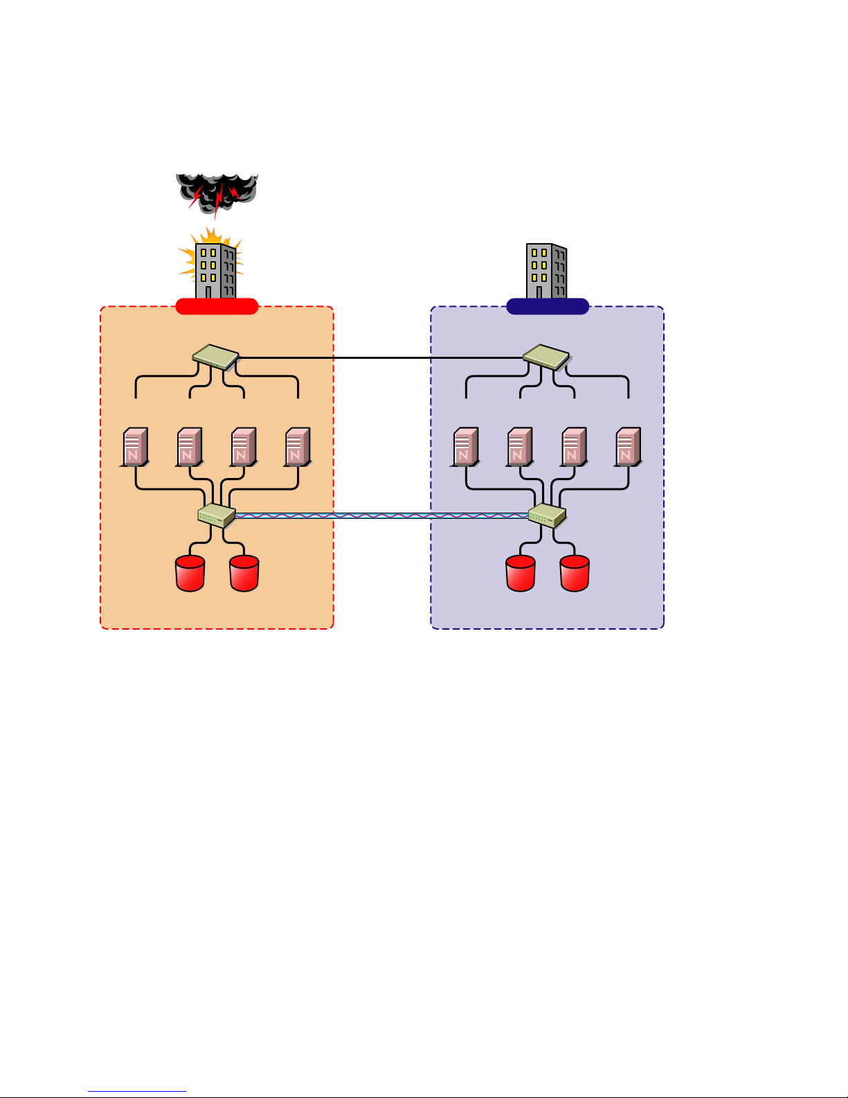
2.11 Business Continuity Cluster Failure Types . . . . . . . . . . . . . . . . . . . . . . . . . . . . . . . . . . . . . . . 43
2.11.1 San-based Mirroring Failure Types and Responses . . . . . . . . . . . . . . . . . . . . . . . . . 44
2.11.2 Host-based Mirroring Failure Types and Responses . . . . . . . . . . . . . . . . . . . . . . . . 45
novdocx (ENU) 10 August 2006
3 Virtual IP Addresses 47
3.1 Virtual IP Address Definitions and Characteristics. . . . . . . . . . . . . . . . . . . . . . . . . . . . . . . . . . 47
3.1.1 Definitions . . . . . . . . . . . . . . . . . . . . . . . . . . . . . . . . . . . . . . . . . . . . . . . . . . . . . . . . . 47
3.1.2 Characteristics. . . . . . . . . . . . . . . . . . . . . . . . . . . . . . . . . . . . . . . . . . . . . . . . . . . . . . 47
3.2 Virtual IP Address Benefits . . . . . . . . . . . . . . . . . . . . . . . . . . . . . . . . . . . . . . . . . . . . . . . . . . . 48
3.2.1 High Availability . . . . . . . . . . . . . . . . . . . . . . . . . . . . . . . . . . . . . . . . . . . . . . . . . . . . . 48
Contents 5
Page 6

3.2.2 Unlimited Mobility . . . . . . . . . . . . . . . . . . . . . . . . . . . . . . . . . . . . . . . . . . . . . . . . . . . . 51
3.3 Other Added Features . . . . . . . . . . . . . . . . . . . . . . . . . . . . . . . . . . . . . . . . . . . . . . . . . . . . . . . 51
3.3.1 Support for Host Mask . . . . . . . . . . . . . . . . . . . . . . . . . . . . . . . . . . . . . . . . . . . . . . . . 51
3.3.2 Source Address Selection for Outbound Connections . . . . . . . . . . . . . . . . . . . . . . . . 51
3.4 Reducing the Consumption of Additional IP Addresses . . . . . . . . . . . . . . . . . . . . . . . . . . . . . . 52
3.5 Configuring Virtual IP Addresses . . . . . . . . . . . . . . . . . . . . . . . . . . . . . . . . . . . . . . . . . . . . . . . 53
3.5.1 Displaying Bound Virtual IP Addresses . . . . . . . . . . . . . . . . . . . . . . . . . . . . . . . . . . . 54
novdocx (ENU) 10 August 2006
6 Novell Business Continuity Cluster Services 1.0 Administration Guide
Page 7

About This Guide
This guide describes how to install, configure, and manage Novell® Business Continuity Clustering.
The guide is intended for cluster administrators and is divided into the following sections:
Chapter 1, “Overview,” on page 9
Chapter 2, “Installation and Setup,” on page 17
Chapter 3, “Virtual IP Addresses,” on page 47
Documentation Conventions
In this documentation, a greater-than symbol (>) is used to separate actions within a step and items
in a cross-reference path.
A trademark symbol (®, ™, etc.) denotes a Novell trademark. An asterisk (*) denotes a third-party
trademark.
novdocx (ENU) 10 August 2006
When a single pathname can be written with a backslash for some platforms or a forward slash for
other platforms, the pathname is presented with a backslash. Users of platforms that require a
forward slash, such as UNIX*, should use forward slashes as required by your software.
About This Guide
7
Page 8

novdocx (ENU) 10 August 2006
8 Novell Business Continuity Cluster Services 1.0 Administration Guide
Page 9

1
Overview
As corporations grow more international, fueled in part by the reach of the World Wide Web, the
requirement for service availability has increased. Novell® Cluster Services™ offers corporations
the ability to maintain 24x7x365 data and application services to their users while still being able to
perform maintenance and upgrades on their systems.
In the past few years, natural disasters (ice storms, earthquakes, tornadoes, and fires) have caused
unplanned outages of entire data centers. In addition, US federal agencies have realized the
disastrous effects that terrorist attacks could have on the US economy when corporations lose their
data and the ability to perform critical business practices. This has resulted in initial
recommendations for corporations to build mirrored or replicated data centers that are
geographically separated by 300 km or more (minimum acceptable being 200 km).
Many companies have built and deployed geographically mirrored data centers. The problem is that
setting up and maintaining the two or more centers is a very manual process that takes a great deal of
planning and synchronizing. Even configuration changes have to be carefully planned and
replicated. One mistake and the redundant site is no longer able to effectively take over in the event
of a disaster.
novdocx (ENU) 10 August 2006
1
1.1 Disaster Recovery Implications
The implications of disaster recovery are directly tied to your data. Is your data mission critical? In
many instances, critical systems and data drive the business. If these services stop, the business
stops. When calculating the cost of downtime, some things to consider are
File transfers and file storage
Calendaring and collaboration
Web hosting
Critical databases
Productivity
Reputation
Continuous availability of critical business systems is no longer a luxury, it is a competitive business
requirement.The Gartner Group estimates that 40% of enterprises that experience a disaster will go
out of business in five years and only 15% of enterprises have a full-fledged business continuity plan
that goes beyond core technology and infrastructure.
1.2 Disaster Recovery Implementations
There are two main Novell Cluster Services implementations that you can use to achieve your
desired level of disaster recovery. These include a stretch cluster and a cluster of clusters. The
Novell Business Continuity Cluster product automates some of the configuration and processes used
in a cluster of clusters.
Overview
9
Page 10

1.2.1 Stretch Clusters vs. Cluster of Clusters
Stretch Clusters
A stretch cluster consists of one cluster in which the nodes in the cluster are located in
geographically separate areas. All nodes in the cluster must be in the same eDirectory™ tree. In this
architecture, the data is mirrored between two data centers that are geographically separated. All the
machines in both data centers are part of one cluster, so that if a disaster occurs in one data center,
the other automatically takes over.
Figure 1-1 Stretch Cluster
8-node cluster stretched
between two sites
Building A Building B
novdocx (ENU) 10 August 2006
Ethernet Switch Ethernet Switch
Server 2
Fibre Channel
Switch
Server 3Server 1 Server 4
Fibre Channel
Disk Array
Site 1
WAN
Cluster
Heartbeat
SAN
Disk blocks
Server 6 Server 7Server 5 Server 8
Fibre Channel
Switch
Fibre Channel
Disk Array
Site 2
Cluster of Clusters
A cluster of clusters consists of two or more clusters in which each cluster is located in a
geographically separate area. A cluster of clusters provides the ability to fail over selected or all
cluster resources from one cluster to another cluster. Typically, replication of data blocks between
10 Novell Business Continuity Cluster Services 1.0 Administration Guide
Page 11
SANs is performed by SAN hardware, but it can be done by host-based mirroring for synchronous
replication over short distances.
Figure 1-2 Cluster of Clusters
Two independent clusters at
geographically separate sites
Building A Building B
novdocx (ENU) 10 August 2006
Server
1A
Fibre Channel
Server
Switch
Ethernet Switch
2A
Fibre Channel
Cluster Site 1
Server
3A
Disk Arrays
Server
4A
WAN
eDirectory
DirXML
SAN
Disk blocks
Server
1B
Ethernet Switch
Server2BServer
3B
Fibre Channel
Switch
Fibre Channel
Disk Arrays
Cluster Site 2
Server
4B
Overview 11
Page 12

Implementation Comparison
Table 1-1 Disaster Recovery Implementation Comparison
Stretch Cluster Cluster of Clusters
novdocx (ENU) 10 August 2006
Advantages It automatically fails over.
It is easier to manage than
separate clusters.
Disadvantages
Failure of site interconnect can
result in LUNs becoming primary
at both locations (split brain
problem) if host-based mirroring
is used.
An SBD partition must be
mirrored between sites.
It accommodates only two sites.
All IP addresses must reside in
the same subnet.
The eDirectory partition must
span the cluster.
The chance of LUNs at both
locations becoming primary is
minimized.
eDirectory partitions don't need
to span the cluster.
Each cluster can be in a
separate eDirectory tree.
IP addresses for each cluster
can be on different IP subnets.
It accommodates more than two
sites and cluster resources can
fail over to separate clusters
(multiple-site fan-out failover
support).
SBD partitions are not mirrored
between sites.
Resource configurations must be
kept in sync manually.
12 Novell Business Continuity Cluster Services 1.0 Administration Guide
Page 13

Stretch Cluster Cluster of Clusters
novdocx (ENU) 10 August 2006
Other Considerations Host-based mirroring is required
to mirror the SBD partition
between sites.
Link variations can cause false
failovers.
You could consider partitioning
the eDirectory tree to place the
cluster container in a partition
separate from the rest of the
tree.
The cluster heartbeat must be
increased to accommodate link
latency between sites.
You can set this as high as 30
seconds, monitor cluster
heartbeat statistics, and then
tune down as needed.
Because all IP addresses in the
cluster must be on the same
subnet, you must ensure that
your routers handle gratuitous
ARP.
Contact your router vendor or
consult your router
documentation for more
information.
Storage arrays must be
controllable by scripts that run on
NetWare.
1.2.2 Novell Business Continuity Clusters
Novell Business Continuity Clusters is a cluster of clusters similar to what is described above,
except that the cluster configuration, maintenance, and synchronization have been automated by
adding specialized software.
Novell Business Continuity Clustering software is an integrated set of tools to automate the setup
and maintenance of a Business Continuity infrastructure. Unlike competitive solutions that attempt
to build stretch clusters, Novell Business Continuity Clustering utilizes a cluster of clusters. Each
site has its own independent cluster(s), and the clusters in each of the geographically separate sites
are each treated as "nodes" in a larger cluster, allowing a whole site to fan-out failover to other
multiple sites. Although this can currently be done manually with a cluster of clusters, Novell
Business Continuity Clustering automates the system using eDirectory and policy-based
management of the resources and storage systems.
Novell Business Continuity Clustering software
Integrates with SAN hardware devices to automate the failover process.
Utilizes Novell's DirXML® technology to automatically synchronize and transfer cluster-
related eDirectory objects from one cluster to another.
Provides the capability to fail over as few as one cluster resource, or as many as all cluster
resources.
Includes a test mode that lets you do site failover testing as a standard practice.
Overview 13
Page 14

Provdes scripting capability for enhanced control and customization.
Provides simplified business coninuity cluster configuration and management using the
browser-based iManager management tool.
1.2.3 Usage Scenarios
There are several Business Continuity Clustering usage scenarios that can be used to achieve the
desired level of disaster recovery. Three possible scenarios include:
A simple two-site Business Continuity Cluster
A multiple-site Business Continuity Cluster
A low-cost Business Continuity Cluster
Two-Site Business Continuity Cluster Solution
The two-site solution can be used in one of two ways:
A primary site in which all services are normally active, and a secondary site which is
effectively idle, with the data mirrored at it and the applications/services ready to load if
needed.
Two active sites each supporting different applications/services. Either site can take over for
the other site at any time.
novdocx (ENU) 10 August 2006
14 Novell Business Continuity Cluster Services 1.0 Administration Guide
Page 15
The first option is typically used when the purpose of the secondary site is primarily testing by the
IT department. The second option is typically used in a company that has more than one large site of
operations.
Figure 1-3 Two Site Business Continuity Cluster
Two independent clusters at
geographically separate sites
Building A Building B
novdocx (ENU) 10 August 2006
Server
1A
Fibre Channel
Server
Switch
Ethernet Switch
2A
Fibre Channel
Cluster Site 1
Server
3A
Disk Arrays
Server
4A
WAN
eDirectory
DirXML
Server
1B
SAN
Disk blocks
Ethernet Switch
Server2BServer
3B
Fibre Channel
Switch
Fibre Channel
Disk Arrays
Cluster Site 2
Server
4B
Multiple-Site Business Continuity Cluster Solution
This is a large Business Continuity Cluster solution capable of supporting up to 32 nodes per site
and more than two sites. Services and applications can do fan-out failover between sites. Replication
of data blocks is typically done by SAN vendors, but can be done by host-based mirroring for
Overview 15
Page 16
synchronous replication over short distances. The illustration below depicts a four-site business
continuity cluster.
Figure 1-4 Multiple Site Business Continuity Cluster
novdocx (ENU) 10 August 2006
Building D
Ethernet Switch
Server2DServer
3C
4B
Fibre Channel
Switch
Fibre Channel
Disk Arrays
Server
4C
Server
3D
Fibre Channel
Switch
4D
Server
1A
Fibre Channel
Switch
Four independent clusters in
geographically separate sites
Building A Building B
Ethernet Switch
Server
Server
2A
Fibre Channel
Disk Arrays
Cluster Site 1
WAN
eDirectory
DirXML
Server
3A
4A
SAN
Disk blocks
Server
Ethernet Switch
Server
Server2BServer
1B
Fibre Channel
Disk Arrays
Cluster Sites 2, 3, and 4
1C
Building C
Ethernet Switch
Server
1D
Server2CServer
Server
3B
Fibre Channel
Switch
Fibre Channel
Disk Arrays
Using Novell’s Portal Services, iChain®, and ZENworks® products, all services, applications, and
data can be rendered through the internet, allowing for loss of service at one site but still providing
full access to the services and data by virtue of the ubiquity of the internet. Data and services
continue to be available from the other mirrored sites. Moving applications and services to the
Internet frees corporations from the restrictions of traditional LAN-based applications. Traditional
LAN applications require a LAN infrastructure that must be replicated at each site, and might
require relocation of employees to allow the business to continue. Internet-based applications allow
employees to work from any place that offers an internet connection, including homes and hotels.
Low Cost Business Continuity Cluster Solution
The low cost business continuity cluster solution is similar to the previous two solutions, but
replaces Fibre Channel arrays with iSCSI arrays. Data block mirroring can be accomplished using
iSCSI-based block replication. In this case, snapshot technology can allow for asynchronous
replication over long distances. However, the lower cost solution does not necessarily have the
performance associated with higher-end Fibre Channel storage arrays.
16 Novell Business Continuity Cluster Services 1.0 Administration Guide
Page 17

2
Installation and Setup
This section covers the following information to help you install, set up, and configure Novell®
Business Continuity Clustering for your specific needs:
“Requirements” on page 17
“Installing the DirXML 1.1a Engine” on page 18
“Installing the DirXML 1.1a Management Utilities” on page 19
“Copying User Objects Using DirXML” on page 22
“Installing Novell Business Continuity Cluster Software” on page 22
“Installing Perl” on page 25
“Configuring File System Mirroring” on page 25
“Setting Up Novell Business Continuity Cluster Software” on page 29
“Managing Novell Business Continuity Clustering” on page 39
“Business Continuity Cluster Failure Types” on page 43
novdocx (ENU) 10 August 2006
2
2.1 Requirements
The following requirements must be met prior to installing Novell Business Continuity Cluster
software.
NetWare® 6.5 Support Pack 2 or later installed and running on all servers that will be part of a
business continuity cluster.
See the NetWare 6.5 Overview and Installation Guide for information on installing and
configuring NetWare 6.5.
Two to four clusters with Novell Cluster Services™ 1.7 (the version that ships with NetWare
6.5 Support Pack 1) or later installed and running on each node in the cluster.
Each cluster must have a unique name, even if the clusters reside in different Novell
eDirectory™ trees, and clusters must not have the same name as any of the eDirectory trees in
the business continuity cluster.
See the Novell Cluster Services 1.7 Administration Guide for information on installing and
configuring Novell Cluster Services.
NOTE: The hardware requirements for Novell Business Continuity Cluster software are the
same as for Novell Cluster Services. For more information, see Hardware Requirements and
Shared Disk System Requirementsin the Novell Cluster Services 1.7 Administration Guide.
NOTE: Some SAN vendors require you to purchase or license their CLI (Command Line
Interface) separately. The CLI for the SAN might not initially be included with your hardware.
The following software modules upgraded on all servers that will be part of the business
continuity cluster:
DSLOADER.NLM--See TID # 2973090 (http://support.novell.com/cgi-bin/search/
searchtid.cgi?/2973090.htm) to download this NLM. It is included with the eDirectory patch.
Installation and Setup
17
Page 18

LIBC.NLM--See TID # 2973643 (http://support.novell.com/cgi-bin/search/searchtid.cgi?/
2973643.htm) to download this NLM.
WINSOCK Suite--See TID # 2971768 (http://support.novell.com/cgi-bin/search/
searchtid.cgi?/2971768.htm) to download this suite. This patch is not needed if you have
installed OES NetWare or NetWare 6.5 SP 3.
DirXML 1.1a Patch--See TID # 2966617 (http://support.novell.com/cgi-bin/search/
searchtid.cgi?/2966617.htm) to download this patch. This patch is not needed for IDM 2.0.x.
For real time mirroring, link speeds should be 1 GB or better, the distance between sites should
be less than 200 kilometers, and the links should be dedicated.
Many factors should be considered for distances greater than 200 kilometers, some of which
include:
The distance between sites
The amount of data being transferred
The bandwidth of the link
Whether or not snapshot technology is being used
novdocx (ENU) 10 August 2006
2.2 Installing the DirXML 1.1a Engine
DirXML® 1.1a or later must be installed on one node in each cluster. DirXML 1.1a is part of the
DirXML Starter Pack that is included with NetWare 6.5. The node where DirXML is installed must
have an eDirectory replica with at least read/write access to all eDirectory objects that will be
synchronized between clusters. This does not apply to all eDirectory objects in the tree.
NOTE: Filtered eDirectory replicas are not supported with this version of Business Continuity
Cluster software. Full replicas are required.
IMPORTANT: The eDirectory replica must have at least read/write access to the following
containers.
The container where the DirXML drivers are located.
The container where the cluster object resides.
The parent container of the container where the server objects reside.
The container where the cluster pool and volume objects will be placed when they are
synchronized to this cluster.
If the eDirectory replica does not have read/write access to the containers listed above,
synchronization will not work properly.
IMPORTANT: If you downloaded NetWare 6.5, DirXML 1.1a might not be included with the
download. You may have to download it separately.
Instructions for installing the DirXML Starter Pack are provided here. For additional information on
installing and configuring DirXML, see the DirXML 1.1a Administration Guide (http://
www.novell.com/documentation/dirxml11a/dirxml/data/a2iii88.html).
To install the DirXML Starter Pack:
1 At the NetWare 6.5 server, insert the DirXML CD into the CD drive.
18 Novell Business Continuity Cluster Services 1.0 Administration Guide
Page 19

2 At the GUI server console, click Novell > Install and then click Add.
If the GUI server console isn't running, launch it by entering STARTX at the console.
3 In the Path to Install From field, browse to and select nw\product.ni on the DirXML CD and
then click OK twice.
4 On the DirXML Product Installation page, click Next.
5 Read the license agreement; if you agree to the terms, click I Accept.
6 On the Components page, mark DirXML Engine and Drivers, then click Next.
7 On the Schema Extension page, enter the following information and then click Next:
User Name: Specify the context of a user who has rights to extend the schema, for
example, CN=admin.O=hq.
User Password: Specify the password for the admin or equivalent user you specified.
8 Select the DirXML Driver for eDirectory, even if you only have one eDirectory tree (your
clusters are in the same eDirectory tree). Click Next.
NOTE: This screen lists all DirXML drivers. Those that cannot be installed on NetWare are
disabled. Drivers that aren't licensed in this bundle, but that can run on NetWare, are labeled
Evaluation. Evaluation drivers require a separate purchase and activation within 90 days of
their installation.
novdocx (ENU) 10 August 2006
NOTE: The DirXML 1.1a driver for eDirectory must be installed on one node in each cluster.
Business Continuity Cluster software will not function correctly if the driver is installed on a
NetWare server that is not a cluster node.
9 Read the Summary page, then click Finish.
The file copy might take a few minutes.
10 After the Installation Complete dialog box is displayed, click Close.
2.3 Installing the DirXML 1.1a Management
Utilities
The DirXML management utilities add the necessary roles and iManager functionality for the
Business Continuity Cluster software. The management utilities can be installed on either a NetWare
6.5 server or a Windows server. Where you install the management utilities depends on where you
access and run iManager. If you choose to install the management utilities on a NetWare server, you
might want to consider a server that is not part of a cluster, but is in the same eDirectory tree as the
cluster. This is because DirXML cannot be failed over from one cluster server to another.
IMPORTANT: Do not install DirXML 2.x management utilities with the DirXML 1.1a engine. If
you do, the DirXML Driver for eDirectory will be converted to version 2.x, and the DirXML 1.1a
engine will no longer be able to get the driver information.
2.3.1 Installing the DirXML Management Utilities on a NetWare
Server
1 At the NetWare 6.5 server where iManager is installed, insert the DirXML CD into the CD
drive.
Installation and Setup 19
Page 20

2 From the GUI server console, click Novell > Install > Add.
If the GUI server console isn't running, launch it by entering STARTX at the console.
3 In the Path to Install From field, browse to and select DirXML_STRTR_PCK\nw\product.ni on
the DirXML CD, then click OK.
4 On the DirXML Product Installation page, click Next.
5 Read the license agreement; if you agree to the terms, click I Accept.
6 On the Components page, mark the following items, then click Next.
DirXML Preconfigured Drivers
Novell iManager Plug-ins for DirXML
7 Verify that all the preconfigured driver files are selected, then click Next.
8 Read the Summary page, then click Finish.
If you are presented with an LDAP warning message, verify that no conflicts exist, then click
OK.
Plug-ins and preconfigured drivers are copied to the Tomcat directory (typically,
sys:tomcat\4\webapps\nps\portal\modules\plugins and
sys:tomcat\4\webapps\nps\DirXML.Drivers) for use during iManager and driver configuration.
The file copy might take a few minutes.
9 At the message directing you to restart your Web services, click OK.
novdocx (ENU) 10 August 2006
10 After the Installation Complete dialog box is displayed, click Close.
11 Restart your Web services using the following sequence:
11a To stop Tomcat, at the System Console prompt, type tc4stop, then press Enter.
Verify that this service is stopped by going to the Logger screen and finding the message
Bootstrap exited successfully.
11b To restart Tomcat, at the System Console prompt, type tomcat4, then press Enter.
Verify that this service is started by going to the Logger screen and finding the message
Jk running....
12 (Conditional) If you are using Assigned Access or Collection Owner Access, make DirXML
roles available by using the iManager Configuration Wizard as explained in the steps that
follow.
12a Launch iManager by going to http://serveripaddress/nps/iManager.html.
IMPORTANT: This URL is case sensitive.
12b Click the Configure button , then click RBS Configuration > Configure iManager.
12c Select either Create a New Collection or Upgrade Collections, then click Next.
NOTE: Fewer collections will improve iManager performance.
12d Select the collections to be updated, then click Next.
12e Select DirXML Utilities and assign a Scope.
TIP: Assign the Scope high enough in the tree to allow access to all DirXML objects
including the server object representing the server where DirXML is installed,
20 Novell Business Continuity Cluster Services 1.0 Administration Guide
Page 21

12f If you are configuring multiple collections, click Next to assign a Scope for each
collection.
12g If you are configuring only one collection, or if this is the final collection that will be
configured, click Start to launch the wizard.
iManager RBS collections are updated.
12h Upon notice of completion, click Close, click Roles and Tasks , then verify that the
following DirXML roles are present:
DirXML Management
DirXML Planning
2.3.2 Installing the DirXML Management Utilities on a Windows
Server
To install the DirXML management utilities on a Windows server where iManager is installed, insert
the DirXML CD into the server, wait for the installation program to start, and then continue through
the installation wizard. During the install, you are given a list of possible components to install.
Ensure that the DirXML Management Utilities component is selected.
novdocx (ENU) 10 August 2006
2.4 Installing DirXML 2.01 (Identity Manager 2.01)
While DirXML 1.1a is the minimum DirXML version required for Business Continuity Clustering,
you can optionally install Identity Manager 2.01 if desired. DirXML is now called Identity Manager.
The same installation program used to install the Identity Manager engine is also used to install the
Identity Manager management utilities. See Installing Identity Manager on NetWare (http://
www.novell.com/documentation/dirxml20/admin/data/abaa2oj.html#abaa2oj) in the Novell Nsure
Identity Manager 2.0.2 Administration Guide.
Identity Manager must be installed on one node in each cluster. The node where Identity Manager is
installed must have an eDirectory replica with at least read/write access to all eDirectory objects that
will be synchronized between clusters. This does not apply to all eDirectory objects in the tree.
NOTE: Filtered eDirectory replicas are not supported with this version of Business Continuity
Cluster software. Full replicas are required.
IMPORTANT: The eDirectory replica must have at least read/write access to the following
containers
The container where the Identity Manager drivers are located.
The container where the cluster object resides.
The parent container of the container where the server objects reside.
The container where the cluster pool and volume objects will be placed when they are
synchronized to this cluster.
If the eDirectory replica does not have read/write access to the containers listed above,
synchronization will not work properly.
Installation and Setup 21
Page 22

2.5 Copying User Objects Using DirXML
The DirXML eDirectory driver has a synchronization feature that will copy objects that exist in one
tree to another tree where they don’t exist. For business continuity clusters, this feature can be used
to copy User objects from one cluster to another cluster in a separate eDirectory tree. For example, if
you have one tree that has 10,000 users and a second new tree that does not yet have users defined,
you can use DirXML to quickly copy the 10,000 users to the new tree.
For more information on copying User objects using DirXML, see Migrating or Copying Objects
(http://www.novell.com/documentation/idmdrivers/index.html?page=/documentation/idmdrivers/
edirectory/data/brj81j4.html) in the Identity Manager Driver for eDirectory Implementation Guide.
2.6 Installing Novell Business Continuity Cluster
Software
It is necessary to run the Novell Business Continuity Clustering installation program when you want
to
Install the Business Continuity Cluster engine software on the cluster nodes that will be part of
a business continuity cluster.
novdocx (ENU) 10 August 2006
Install the iManager snap-ins for Business Continuity on either a NetWare 6.5 server or a
Windows server.
When you run the installation program to install the Business Continuity Cluster engine software,
the eDirectory schema is automatically extended in the eDirectory tree where the engine software is
installed.
The Business Continuity Cluster installation installs to only one cluster at a time You must run the
installation program again for each cluster.
The Business Continuity Cluster installation program is run from a Windows workstation. Prior to
running the installation program, the Windows workstation must have the latest Novell Client™
software installed and you must be authenticated to the eDirectory tree where the cluster resides.
You must also have a client connection established from the workstation running the installation
program to all servers in the cluster where Business Continuity Cluster software will be installed.
The easiest way to do this is to use Windows Explorer to browse the eDirectory tree to the sys:
volume of each server in your cluster to be upgraded or installed. Opening the sys: volume folder on
a server automatically creates a connection to that server.
2.6.1 Business Continuity Cluster Licensing
Novell Business Continuity Cluster software requires a paper license agreement for each business
continuity cluster.
22 Novell Business Continuity Cluster Services 1.0 Administration Guide
Page 23

2.6.2 Running the Business Continuity Cluster Installation
Program
To install Novell Business Continuity Clustering, download and copy the software to a directory on
your Windows workstation, then complete the following steps:
1 From the directory on your Windows workstation where you just copied the Business
Continuity software, run install.exe.
2 Continue through the installation wizard until you get to the screen that prompts you to select
the components to install.
3 Select the Business Continuity Cluster engine component and at least one of the iManager
snap-ins installation options, then click Next.
The Business Continuity Cluster Engine contains the core software engine files that make up
the Business Continuity Cluster product. The Business Continuity Cluster engine must be
installed on the cluster nodes in each cluster that will be part of a Business Continuity Cluster.
Selecting the iManager Snap-ins for Novell NetWare-Based Management Servers installs the
snap-ins on a NetWare server. The snap-ins add functionality to iManager so you can manage
your Business Continuity Cluster. You will be asked to specify the NetWare server where the
snap-ins will be installed later in the installation.
novdocx (ENU) 10 August 2006
Selecting the iManager Snap-ins for Microsoft* Windows-Based Management Servers installs
the snap-ins on the Windows server you specify. You must have iManager installed on the
Windows server before installing the snap-ins. The snap-ins add functionality to iManager so
you can manage your business continuity cluster. You will be asked to specify the path to
Tomcat (a default path is provided) on the Windows server later in the installation.
4 Specify the name of the eDirectory tree and the fully distinguished name for the cluster where
you want to install the core software engine files.
If you don’t know the fully distinguished name for the cluster, you can browse and select it.
5 Select the servers in the cluster where you want to install the core software engine files for the
Business Continuity Cluster product.
All servers currently in the cluster you specified are listed and are selected by default.
You can choose to automatically start Business Continuity Cluster software on each selected
node after the installation is complete. If Business Continuity Cluster software is not started
automatically after the installation, you can start it manually later by rebooting the cluster
server or by entering LDBCC at the server console.
6 Do one of the following:
(Conditional) If you chose to install the iManager snap-ins on a NetWare server, specify
the name of the eDirectory tree and the fully distinguished name for the server where you
want to install the iManager snap-ins. Then click Next.
If you don’t know the fully distinguished name for the server, you can browse and select
it.
(Conditional) If you chose to install the iManager snap-ins on a Windows server, specify
the path to Tomcat (a default path is provided) on the server. Then click Next.
You must have iManager installed on the Windows server before installing the snap-ins.
7 Continue through the final installation screen and then restart each node in the cluster.
Installation and Setup 23
Page 24

The Business Continuity Cluster software installation program upgrades some of the core
cluster NLM™ programs (or files). Because of this, you must restart each cluster node before
performing further configuration or using your business continuity clusters.
Restarting the cluster nodes can be performed in a rolling fashion in which one server is
restarted while the other servers in the cluster continue running. Then another server is
restarted, and then another, until all servers in the cluster have been restarted.
This lets you keep your cluster up and running and lets your users continue to access the
network while cluster nodes are being restarted.
8 Repeat the above procedure for each cluster that will be part of the business continuity cluster.
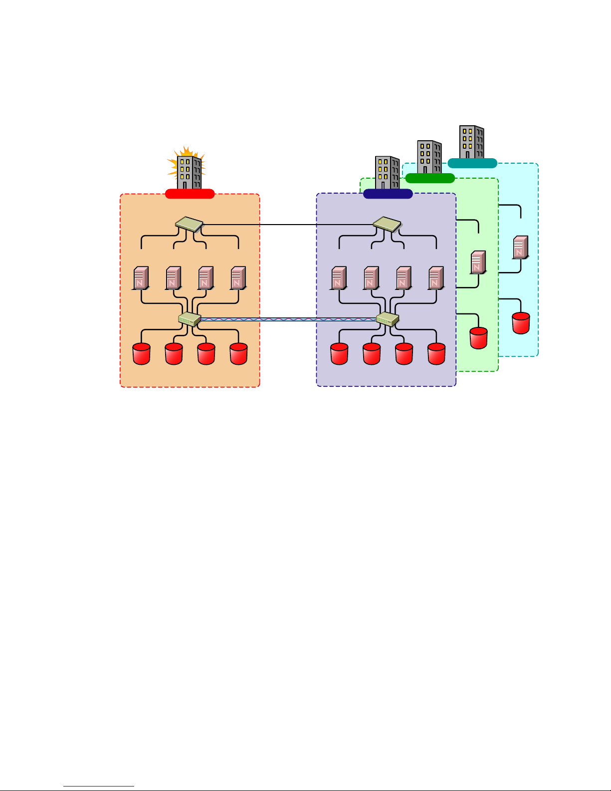
2.6.3 Business Continuity Cluster Component Locations
The following figure illustrates where the various components needed for a business continuity
cluster are installed.
Figure 2-1 Business Continuity Cluster Component Locations
novdocx (ENU) 10 August 2006
Server
A
DirXML
Managment
Utilities
BCC
iManager
plug-ins
Fibre Channel
Building A
Ethernet Switch
NW 6.5
iManager
Server
1A
Switch
Fibre Channel
Disk Arrays
Cluster Site 1
Server
2A
NW 6.5
NCS
BCC eng.
NW 6.5
NCS
BCC eng.
Server
3A
NW 6.5
NCS
BCC eng.
DirXML eng.
WAN
eDirectory
DirXML
SAN
Disk blocks
NW 6.5
NCS
BCC eng.
DirXML eng.
NW 6.5
NCS
BCC eng.
Server
1B
Building B
Ethernet Switch
Server
2B
NW 6.5
iManager
NW 6.5
NCS
BCC eng.
Fibre Channel
Disk Arrays
Cluster Site 2
Server
DirXML
Server
Managment
3B
Utilities
BCC
iManager
plug-ins
Fibre Channel
Switch
B
Figure 2-1 uses the following abbreviations:
BCC eng. -- Business Continuity Cluster engine
NCS -- Novell Cluster Services
NW 6.5 -- NetWare 6.5
24 Novell Business Continuity Cluster Services 1.0 Administration Guide
Page 25

2.7 Installing Perl
Perl scripts are included with the Novell Business Continuity Clustering product and add
functionality that lets you manage your business continuity cluster using cluster-specific commands
either at the NetWare server console or in a DOS window on a Windows workstation.
The Perl script engine needed for Business Continuity Cluster software is included and installed
with NetWare 6.5 Support Pack 2. The Perl scripts needed for Business Continuity Clustering are
installed on cluster servers with the Business Continuity Cluster engine.
If you want to install the Perl script engine (version 5.8.0 or later is required) on a Windows
management workstation, you can download it for free from Perl Web site (http://
www.activestate.com). The Perl scripts needed for Business Continuity Clustering can also be
installed on your Windows workstation. To do this, copy the following files from the
sys:\perl\scripts directory on your NetWare server to a directory on you Windows workstation:
ClusterCli.pl
ClusterCliSnapinInterface.pm
ClusterCliUtils.pm
novdocx (ENU) 10 August 2006
A snapins directory is located under the directory where the files listed above are located on the
NetWare server. You must also copy the snapins directory and its entire contents so that it appears as
a subdirectory under the directory on your Windows workstation where you copied the files listed
above.
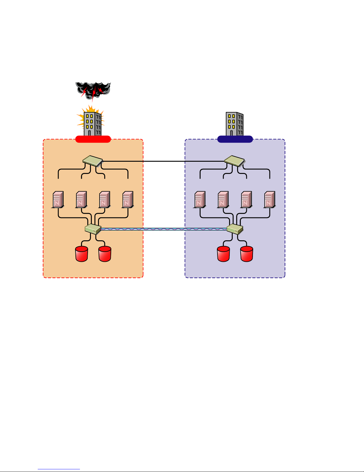
2.8 Configuring File System Mirroring
Several different methods and scenarios for mirroring data between geographically separate sites
exist. Each method has its own strengths and weaknesses. After considering the different methods,
you will need to choose either host-based mirroring or SAN-based mirroring (also called arraybased mirroring) and whether you want the mirroring to be synchronous or asynchronous.
SAN-based synchronous mirroring is preferred and is provided by SAN hardware manufacturers.
Host-based synchronous mirroring functionality is included with the NSS file system (NSS
mirroring) that is part of NetWare 6.5.
Installation and Setup 25
Page 26

NSS mirroring is a checkpoint-based synchronous mirroring solution. Data blocks are written
synchronously to multiple storage devices. It is an alternative to SAN array-based synchronous
replication options.
Figure 2-2 Synchronous Mirroring
Synchronous
Mirroring
Building A Building B
novdocx (ENU) 10 August 2006
Ethernet Switch
Server 2
Fibre Channel
Switch
Server 3Server 1 Server 4
Changes
Completion
Fibre Channel
Disk Array
Ethernet Switch
Server 6 Server 7Server 5 Server 8
Fibre Channel
Switch
Fibre Channel
Disk Array
MirrorOriginal
2.8.1 Configuring NSS Mirroring
NSS partitions must be mirrored after they are created. If you have an existing partition that you
want to mirror, you can either create another partition of equal size on another device to mirror the
first partition to, or let the mirroring software automatically create another partition of equal size on
another device.
When you create a Novell Cluster Services system that utilizes shared storage space (a Storage Area
Network or SAN), it is important to remember that all servers attached to the shared device, whether
in the cluster or not, have access to all of the volumes on the shared storage space unless you
specifically prevent such access. Novell Cluster Services arbitrates access to shared volumes for all
cluster nodes, but cannot protect shared volumes from being corrupted by noncluster servers.
Creating and Mirroring NSS Partitions on Shared Storage
Prior to creating and mirroring NSS partitions on shared storage, ensure that you have
All servers in the cluster connected to a shared storage system
One or more drive arrays configured on the shared storage system
At least 15 MB of free space on the shared storage system for a special cluster partition
26 Novell Business Continuity Cluster Services 1.0 Administration Guide
Page 27

To create and mirror NSS partitions:
1 Start NSSMU by entering NSSMU at the server console of a cluster server.
2 Select Partitions from the NSSMU main menu.
3 Press the Insert key and select the device on your shared storage system where you want to
create a partition.
If a device is marked as sharable for clustering, all partitions on that device are automatically
sharable.
Device names are not changeable and might be labeled something like 0x2 or 0x1.
If Cluster Services was previously installed and shared disk partitions were already created, the
Partitions List will include this information.
4 Select NSS as the partition type, then specify the partition size and, if desired, an NSS pool
name and label.
If you specify a pool name, a pool by that name will automatically be created on the partition. If
no pool name is specified, you will have to create a pool on the partition later.
4a If you chose to create a pool, choose whether you want the pool to be activated and cluster
enabled when it is created.
novdocx (ENU) 10 August 2006
The Activate on Creation feature is enabled by default. This causes the pool to be
activated as soon as it is created. If you choose not to activate the pool, you will have to
manually activate it later before it can be used.
The Cluster Enable on Creation feature is also enabled by default. If you want to cluster
enable the pool at the same time it is created, accept the default entry (Yes) and continue
with Step 4b. If you want to cluster enable the pool at a later date, see the Novell Cluster
Services 1.7 Administration Guide for more information.
4b Specify the Virtual Server Name, IP Address, Advertising Protocols and, if necessary, the
CIFS Server Name.
When you cluster-enable a pool, a virtual Server object is automatically created and given
the name of the Cluster object plus the cluster-enabled pool. For example, if the cluster
name is cluster1 and the cluster-enabled pool name is pool1, then the default virtual server
name will be cluster1_pool1_server. You can edit the field to change the default virtual
server name.
Each cluster-enabled NSS pool requires its own IP address. The IP address is used to
provide access and failover capability to the cluster-enabled pool (virtual server). The IP
address you assign to the pool remains assigned to the pool regardless of which server in
the cluster is accessing the pool.
You can select one or all of the advertising protocols. NCP™ is the protocol used by
Novell clients, CIFS is the protocol used by Microsoft clients, and AFP is the protocol
used by Macintosh* clients. Selecting any of the protocols causes lines to be added to the
pool resource load and unload scripts to activate the selected protocols on the cluster. This
lets you ensure that the cluster-enabled pool you just created is highly available to all your
clients.
If you select CIFS as one of the protocols, a CIFS Server Name is also required. This is the
server name CIFS clients see when they browse the network. A default server name is
listed, but you can change the server name by editing the text in the field.
4c Select Create to create and cluster-enable the pool.
Installation and Setup 27
Page 28

5 Select the partition you want to mirror (this might be the partition you just created) and press
the F3 key.
6 Select the device with free space or the partition you want to mirror to, then select YES to
mirror the partition.
To ensure disaster recovery, the device you select to mirror should be in another storage array.
Creating an NSS Pool and Volumes
After an NSS partition has been created and mirrored, if you have not already done so, you must
create an NSS pool and volume on that partition. To do this, follow the instructions in "Create NSS
Pools " in the Installation and Setup section of the Novell Cluster Services 1.7 Administration Guide.
Novell Cluster Services Configuration and Setup
After configuring NSS mirroring and creating a pool and volume on the mirrored NSS partition, if
you did not cluster-enable the NSS pool on the mirrored partition when you created it, do so by
following the instructions in the Installation and Setup section of the Novell Cluster Services 1.7
Administration Guide.
novdocx (ENU) 10 August 2006
When you cluster-enable a shared disk pool, the commands to start and stop the pool resource are
automatically added to the resource load and unload scripts.
Checking NSS Volume Mirror Status
After you have configured NSS mirroring with Novell Cluster Services, you should check to ensure
that it is working properly in a cluster environment.
1 Ensure that the volumes on the cluster-enabled pool are mounted on an assigned server by
entering volumes at the server console.
2 Check the mirror status of the mirrored partition by entering mirror status at the server
console of the server where the NSS pool on the mirrored partition is active.
After entering mirror status, you should see a message indicating that mirror status is 100
percent or a message indicating that the mirrored object is fully synchronized.
3 Migrate the pool to another server in the cluster and again check to ensure the volumes on the
pool are mounted by entering volumes at the server console.
4 Check the mirror status of the partition again by entering mirror status at the server
console.
IMPORTANT: If you create or delete a pool or partition on shared storage that is part of a business
continuity cluster, you must run the cluster scan for new devices command on a server
in each of the other clusters that belong to the business continuity cluster.
2.8.2 LUN Masking
We recommend that you implement LUN masking in your business continuity cluster for data
protection. LUN masking is provided by your SAN vendor.
LUN masking is the ability to exclusively assign each LUN to one or more host connections. With it
you can assign appropriately sized pieces of storage from a common storage pool to various servers.
See your SAN vendor documentation for more information on configuring LUN masking.
28 Novell Business Continuity Cluster Services 1.0 Administration Guide
Page 29

2.9 Setting Up Novell Business Continuity
Cluster Software
After you have installed and configured DirXML, the Business Continuity Cluster software, and
Perl, and you have configured file system mirroring, you need to set up Novell Business Continuity
Cluster software. Instructions contained in this section for setting up Novell Business Continuity
Cluster software consists of:
“Ensuring that Clusters and Trees are Resolvable” on page 29
“Configuring Business Continuity-Specific DirXML Drivers” on page 29
“Configuring Clusters for Business Continuity” on page 34
“Configuring Cluster Resources for Business Continuity” on page 36
2.9.1 Ensuring that Clusters and Trees are Resolvable
Ensuring that each cluster is resolvable to other cluster nodes and eDirectory trees means that each
cluster can contact all nodes in the other clusters in the business continuity cluster, even if other
nodes are in different eDirectory trees. You can do this by pinging the IP addresses of the nodes in
the other clusters in the business continuity cluster. You can further ensure that each cluster is
resolvable by adding the cluster name with the master IP address and the eDirectory tree name with
the master IP address to the host file of each node in the business continuity cluster.
novdocx (ENU) 10 August 2006
Using a text editor, edit the sys:\etc\hosts file of each server in each cluster and add the cluster name
and the cluster IP address for each cluster in the business continuity cluster. Also add the eDirectory
tree name and master IP address. The new entries to the host file may look similar to the following
example:
# Entries for the Business Continuity Cluster (BCC)
123.45.67.181 BCC_Cluster.provo.novell.com BCC_Cluster
123.45.67.180 BCC_TREE
You can also use the other server names, eDirectory tree names, and IP addresses listed in the Hosts
file as an example of the proper format. Each cluster should resolve to an eDirectory master replica
holder of the cluster container and server container objects.
2.9.2 Configuring Business Continuity-Specific DirXML Drivers
The DirXML preconfigured templates for iManager that were installed when you ran the Business
Continuity Cluster (BCC) installation must be configured so you can properly manage your business
continuity cluster. The preconfigured templates include a template for User object synchronization
and a template for cluster resource synchronization. User object synchronization must be configured
if you have more than one eDirectory tree in your business continuity cluster. Cluster resource
synchronization must always be configured.
IMPORTANT: DirXML or Identity Manager must be installed on one node in each cluster. The
node where DirXML or Identity Manager is installed must have an eDirectory replica with at least
read/write access to all eDirectory objects that will be synchronized between clusters. This does not
apply to all eDirectory objects in the tree.
Installation and Setup 29
Page 30

The eDirectory replica must have at least read/write access to the following containers
The container where the DirXML or Identity Manager drivers are located.
The container where the cluster object resides.
The parent container of the container where the server objects reside.
The container where the cluster pool and volume objects will be placed when they are
synchronized to this cluster.
If the eDirectory replica does not have read/write access to the containers listed above,
synchronization will not work properly.
NOTE: Filtered eDirectory replicas are not supported with this version of Business Continuity
Cluster software. Full replicas are required.
To configure the DirXML drivers/templates:
1 Start Internet Explorer 5 or later and enter the URL for iManager.
The URL is http://server_ip_address/nps/imanager.html. Replace server_ip_address with the
IP address or DNS name of the NetWare 6.5 server that has iManager and the DirXML
preconfigured templates for iManager installed.
2 Enter your username and password.
3 In the left column, click DirXML Management (or DirXML Utilities if the iManager plug-in
has been updated), then click the Create Driver link.
4 Choose to place the new driver in a new driver set.
Both the User object synchronization driver and the cluster resource synchronization driver can
be added to the same driver set.
5 Specify the driver set name, context, and the server that the driver set will be associated with.
The server is the same server where you installed the DirXML engine and eDirectory driver.
novdocx (ENU) 10 August 2006
6 Choose to create a new partition for the driver set, then click Next.
Choosing to create a new partition helps keep the driver set separate from other partition
operations.
7 Choose to import a preconfigured driver from the server, then select the DirXML
preconfigured template for cluster resource synchronization.
The template name is BCCClusterResourceSynchronization.XML.
8 Fill in the values on the wizard page as prompted, then click Next.
Each field contains an example of the type of information that should go into the field.
Descriptions of the information required are also included with each field.
Additional information for the wizard page fields includes:
Driver name: Enter a unique name for this driver that will identify its function. For
example, Cluster1SyncCluster2. If you use both preconfigured templates, you must
specify different driver names for each driver template.
Name of SSL Certificate: If you do not have an SSL certificate, leave this value set to
the default. The certificate will be created later in the configuration process. See Step 1 on
page 32 for instructions on creating SSL certificates.
30 Novell Business Continuity Cluster Services 1.0 Administration Guide
Page 31

Name of other DirXML server: Enter the DNS name or IP address of the DirXML
server in the other cluster.
Port number for this driver : If you use both preconfigured templates, you must specify
different port numbers for each driver template.
The default port number is 2002. You might want to specify 2001 as the port number for
one of the driver templates.
You must specify the same port number for the same template in the other clusters. For
example, if you specify 2001 as the port number for the resource synchronization
template, you must specify 2001 as the port number for the resource synchronization
template in the other clusters.
Full Distinguished Name (DN) of this cluster : For example, Cluster1.siteA.Novell.
Full Distinguished Name (DN) of other cluster : Enter the fully Distinuished Name
(DN) of the cluster in the other tree that is to be mirrored. For example
Cluster2.siteB.Novell.
Context where cluster-enabled pool and volume objects will be synchronized for this
cluster : Enter the context of the container where the cluster pool and volume objects in
the other cluster will be placed when they are synchronized to this cluster. The context
must already exist and must be specified using dot format without the tree name. For
example, siteA.Novell.
Prior to performing this step, you could create a separate container in eDirectory specificly
for these cluster pool and volume objects. You would then specify the context of the new
container in this step.
Parent container context of cluster-enabled pool and volume objects for other
cluster : Enter the context (using dot format without the tree name) of the container where
the cluster pool and volume objects in the other cluster currently reside. This context must
be a parent container to all contexts where cluster-enabled pool and voume objects for the
other cluster reside. For example siteB.Novell.
novdocx (ENU) 10 August 2006
Prior to performing this step, you could create a separate container in eDirectory specificly
for these cluster pool and volume objects. You would then specify the context of the new
container in this step.
Name of other tree : Enter the name of the tree where the other cluster is located. This
could be the same tree if the clusters are in the same eDirectory tree.
The DirXML Driver object must have sufficient rights to create, mofify, and delete objects and
attributes in the container where the cluster objects reside, and if necessary, in the container
where the user objects reside. You can do this by making the DirXML Driver object security
equivalent to the Admin User object or to another user object with those rights. See Step 9 on
page 31.
If you choose to include User object synchronization, exclude the Admin User object from
being synchronized. See Step 11 on page 32.
You can also exclude the Cluster Resource Driver object from being synchronized. This is
recommended, but not required.
9 Make the DirXML Driver object security equivalent to an administrative User object.
The DirXML Driver object must have sufficient rights to create, mofify, and delete objects and
attributes in the container where the cluster objects reside, and if necessary, in the container
where the user objects reside. You can do this by making the DirXML Driver object security
equivalent to the Admin User object or to another user object with those rights.
Installation and Setup 31
Page 32

9a Click the Define Security Equivalences button, then click Add.
9b Browse to and select the desired User object, then click OK.
9c Click Next, and then click Finish.
10 (Optional) If you want to synchronize User objects between clusters in separate trees, repeat
Step 1 through Step 9, and in Step 7, select the preconfigured template for User object
synchronization.
The template name is BCCUserObjectSynchronization.XML.
To synchronize User objects
10a In the left column of the iManager page, click DirXML and then click DirXML Overview.
10b Search for the eDirectory tree for the DirXML driver sets by clicking Search.
10c Click the User Sync driver icon, then click Migrate from eDirectory.
10d Click Add, browse to and select the context that contains the User objects, then click OK.
11 (Optional) If you choose to include user object synchronization, exclude the Admin User object
from being synchronized.
11a Click the Exclude Administrative Roles button, then click Add.
novdocx (ENU) 10 August 2006
11b Browse to and select the Admin User object, then click OK.
12 If the other clusters in your business continuity cluster are in different eDirectory trees, perform
Step 1 through Step 11 for each cluster that is in a separate tree.
Creating SSL Certificates
You must create an an SSL certificate for the cluster resource synchronization driver, and if you
have configured user object synchronization, an SSL certificate for the user object synchronization
driver. Creating one certificate creates that certificate for a driver pair. For example, creating an SSL
certificate for the cluster resource synchronization driver creates the certificate for the cluster
resource synchronization drivers on both clusters.
To create an SSL certificate:
1 Start Internet Explorer 5 or later and enter the URL for iManager.
The URL is http://server_ip_address/nps/imanager.html. Replace server_ip_address with the
IP address or DNS name of the NetWare 6.5 server that has iManager and the DirXML
preconfigured templates for iManager installed.
2 Enter your username and password.
3 In the left column, click DirXML Management, then click NDS2NDS Driver Certificates.
4 Enter the requested driver information for both eDirectory trees.
You must specify the driver name (including the context) you supplied in Step 8 on page 30 for
the current tree. Use the following format when specifying the driver name:
DriverName.DriverSet.OrganizationalUnit.OrganizationName
Ensure there are no spaces (beginning or end) in the specified context, and do not use the
following format:
cn=DriverName.ou=OrganizationalUnitName.o=OrganizationName
32 Novell Business Continuity Cluster Services 1.0 Administration Guide
Page 33

Synchronizing DirXML Drivers
After creating BCC-specific DirXML drivers and SSL certificates, if you are adding a new cluster to
an existing business continuity cluster, you must synchronize the BCC-specific DirXML drivers. If
BCC-specific DirXML drivers are not synchronized, clusters can't be enabled for business
continuity. This is not necessary unless you are adding a new cluster to an existing business
continuity cluster.
To synchronize BCC-specific DirXML drivers:
1 Start Internet Explorer 5 or later and enter the URL for iManager.
The URL is http://server_ip_address/nps/imanager.html. Replace server_ip_address with the
IP address or DNS name of the NetWare 6.5 server that has iManager and the DirXML
preconfigured templates for iManager installed.
2 Enter your username and password.
3 In the left column, click DirXML Management, then click the Overview link.
4 Search for and find the BCC driver set.
5 Click the Cluster Sync icon and then click the Synchronize button.
6 If you chose to include User object synchronization, repeat the above steps, and in Step 5 click
the User Sync icon.
novdocx (ENU) 10 August 2006
Preventing DirXML Synchronization Loops
If you have three or more clusters each in separate eDirectory trees in your business continuity
cluster, you should set up DirXML user object and cluster resource object synchronization in a
manner that prevents DirXML synchronization loops. DirXML synchronization loops can cause
excessive network traffic and slow server communication and performance.
For example, in a three cluster business continuity cluster, a DirXML synchronization loop occurrs
when cluster one is configured to synchronize with cluster two, cluster two is configured to
synchronize with cluster three, and cluster three is configured to synchronize back to cluster one.
This is illustrated in Figure 2-3 below.
Figure 2-3 Three Cluster DirXML Synchronization Loop
Cluster
One
DirXML Sync
DirXML Sync
DirXML Sync
Cluster
Three
Cluster
Tw o
Installation and Setup 33
Page 34

A preferred method is to make cluster one a DirXML synchronization master in which cluster one
synchronizes with cluster two and cluster two and cluster three both synchronize with cluster one.
This is illustrated in Figure 2-4 below.
Figure 2-4 Three Cluster DirXML Synchronization Master
Cluster
One
DirXML Sync
DirXML Sync
novdocx (ENU) 10 August 2006
Cluster
Three
Cluster
Tw o
You could also have cluster one synchronize with cluster two, cluster two synchronize with cluster
three, and cluster three synchronize back to cluster two as is illustrated in Figure 2-5 below.
Figure 2-5 Alternate Three Cluster DirXML Synchronization Scenario
Cluster
One
DirXML Sync
DirXML Sync
Cluster
Three
Cluster
Tw o
2.9.3 Configuring Clusters for Business Continuity
This procedure consists of
“Enabling Clusters for Business Continuity” on page 35
“Adding Cluster Peer Credentials” on page 35
“Adding Resource Script Search and Replace Values” on page 36
These tasks must be performed on each separate cluster that you want to be part of the business
continuity cluster.
34 Novell Business Continuity Cluster Services 1.0 Administration Guide
Page 35

Enabling Clusters for Business Continuity
If you want to enable the ability for a cluster to fail over selected resources or all cluster resources to
another cluster, you must enable business continuity on that cluster.
1 Start Internet Explorer 5 or later and enter the URL for iManager.
The URL is http://server_ip_address/nps/imanager.html. Replace server_ip_address with the
IP address or DNS name of the NetWare 6.5 server that has iManager and the DirXML
preconfigured templates for iManager installed. This server should be in the same eDirectory
tree as the cluster you are enabling for business continuity.
2 Enter your username and password.
3 Ensure the Business Continuity-specific DirXML drivers are running.
3a In the left column, click DirXML Management and then click the Overview link.
3b Search the eDirectory Container or tree for the Business Continuity-specific DirXML
drivers.
3c Click the upper-right corner of the driver icon(s) to see if the driver is started or stopped.
If the driver is stopped, you can start it by choosing Start.
novdocx (ENU) 10 August 2006
4 In the left column, click Cluster Administration and then click the Configuration link.
5 Specify a cluster name or browse and select one.
6 Click the Properties button, then click the Business Continuity tab.
7 Ensure the Enable Business Continuity Features check box is selected.
8 Repeat Step 1 through Step 7 for the other cluster that this cluster will migrate resources to.
9 Continue with Step 1 in the Adding Cluster Peer Credentials section below.
Adding Cluster Peer Credentials
In order for one cluster to connect to a second cluster, the first cluster must be able to authenticate to
the second cluster. To make this possible, you must add the administrator username and password
that the selected cluster will use to connect to the selected peer cluster.
IMPORTANT: In order to add or change cluster peer credentials, you must access iManager on a
server that is in the same eDirectory tree as the cluster you are adding or changing peer credentials
for.
1 In the Connections section of the Business Continuity Cluster Properties page, select one or
more peer clusters and then click Edit.
In order for a cluster to appear in the list of possible peer clusters, that cluster must
Have Business Continuity Cluster software installed.
Have DirXML installed.
Be resolvable to the other clusters and eDirectory trees.
Have business continuity-specific DirXML drivers configured and running.
Be enabled for business continuity.
2 Add the administrator username and password that the selected cluster will use to connect to
the selected peer cluster.
Installation and Setup 35
Page 36

When specifying a username, include the Novell eDirectory context for it.
If you selected multiple peer clusters, specify a common administrator username and password
for the selected peer clusters. Each cluster can then use the same username and password to
connect to multiple peer clusters.
3 Repeat Step 1 and Step 2 for the other cluster that this cluster will migrate resources to.
4 Continue with Step 1 in the Adding Resource Script Search and Replace Values section below.
Adding Resource Script Search and Replace Values
To enable a resource for business continuity, certain values (such as IP addresses) specified in
resource load and unload scripts need to be changed in corresponding resources in the other clusters.
You need to add the search and replace strings that are used to transform cluster resource load and
unload scripts from this cluster to another cluster.
TIP: You can see the IP addresses that are currently assigned to resources by entering the display
secondary ipaddress command at the NetWare server console of cluster servers.
The search and replace data is cluster specific, and it is not synchronized via DirXML between the
clusters in the business continuity cluster.
novdocx (ENU) 10 August 2006
To add resource script search and replace values:
1 In the Resource Script Replacements section of the Business Continuity Cluster Properties
page, click New.
2 Add the desired search and replace values, then click OK.
The search and replace values you specify here apply to all resources in the cluster that have
been enabled for business continuity.
For example, if you specified 10.1.1.1 as the search value and 192.168.1.1 as the replace value,
the resource with the 10.1.1.1 IP address in its scripts would be searched for in the primary
cluster and, if found, the 192.168.1.1 IP address would be assigned to the corresponding
resource in the secondary cluster.
You can also specify global search and replace addresses for multiple resources in one line.
This can be used only if the last digits in the IP addresses are the same in both clusters. For
example, if you specify 10.1.1 as the search value and 192.168.1 as the replace value, the
software finds the 10.1.1.1, 10.1.1.2, 10.1.1.3 and 10.1.1.4 addresses and then replaces them
with the 192.168.1.1, 192.168.1.2, 192.168.1.3, and 192.168.1.4 addresses, respectivley.
2.9.4 Configuring Cluster Resources for Business Continuity
Cluster resources can be configured for business continuity either at the same time they are created
or after they are created. Configuring a resource for business continuity consists of enabling that
resource for business continuity, adding load and unload script search and replace data specific to
the resource, and selecting peer clusters for the resource.
NOTE: In a business continuity cluster, you should have only one NSS pool for each LUN that
could be failed over to another cluster. This is necessary because in a business continuity cluster,
entire LUNs fail over to other clusters, rather than individual pools, which fail over to other nodes
within a cluster.
36 Novell Business Continuity Cluster Services 1.0 Administration Guide
Page 37

Enabling a Cluster Resource for Business Continuity
Cluster resources must be enabled for business continuity on the primary cluster before they can be
synchronized and appear as resources in the other clusters in the business continuity cluster.
Enabling a cluster resource makes it possible for that cluster resource or cluster pool resource to be
migrated to another cluster.
IMPORTANT: Although you can add search and replace data that is resource-specific after you
enable a resource for business continuity, we recommend adding the search and replace data for the
entire cluster before you enable resources for business continuity. See “Adding Resource Script
Search and Replace Values” on page 36 for instructions on adding search and replace data for the
entire cluster.
1 (Conditional) If you are creating a new cluster resource or cluster pool resource, follow the
instructions for creating a cluster resource or cluster pool resource using iManager in the Novell
Cluster Services 1.7 Administration Guide, then continue with Step 3 below.
If you have Business Continuity Clustering software installed and configured, at the end of the
resource creation process, the wizard for creating a cluster resource will display a page for
enabling the resource for business continuity.
novdocx (ENU) 10 August 2006
2 (Conditional) If you are enabling an existing cluster resource or cluster pool resource for
business continuity, do the following:
2a Start Internet Explorer 5 or later and enter the URL for iManager.
The URL is http://server_ip_address/nps/imanager.html. Replace server_ip_address with
the IP address or DNS name of the NetWare 6.5 server that has iManager and the DirXML
preconfigured templates for iManager installed.
2b Enter your username and password.
2c In the left column, click Cluster Administration, then click the Configuration link.
2d Specify a cluster name or browse and select one.
2e Select the desired cluster resource from the list of Cluster objects
2f Click the Properties link (not the Properties button), then click the Business Continuity
tab.
3 Ensure that the Enable Business Continuity Features check box is selected.
4 Continue with Step 1 in the Adding Resource Script Search and Replace Values section.
Adding Resource Script Search and Replace Values
If you did not previously add search and replace data specific to the entire cluster, you must now add
it for this resource.
To enable a resource for business continuity, certain values (such as IP addresses, DNS names, and
tree names) specified in resource load and unload scripts need to be changed in corresponding
resources in the other clusters. You need to add the search and replace strings that are used to
transform cluster resource load and unload scripts from this cluster to another cluster.
The search and replace data you add is resource specific, and it is not synchronized via DirXML
between the clusters in the business continuity cluster.
Installation and Setup 37
Page 38

To add resource script search and replace values specific to this resource:
1 In the Resource Script Replacements section of the page, click New.
If a resource has already been configured for business continuity, you can click Edit to change
existing search and replace values or click Delete to delete them.
2 Add the desired search and replace values, then click OK.
The search and replace values you specify here apply to only to the resource you are enabling
for business continuity. If you want the search and replace values to apply to any or all cluster
resources, add them to the entire cluster instead of just to a specific resource.
See “Adding Resource Script Search and Replace Values” on page 36 for more information on
resource script search and replace values and adding those values to the entire cluster.
3 If this is an existing cluster resource, continue with Step 1 in the Selecting Peer Clusters for the
Resource section below. If you are creating a new cluster resource, click Next, then continue
with Step 1 in the Selecting Peer Clusters for the Resource section below.
IMPORTANT: If you change the resource-specific search and replace data after intitially adding it,
you must update the resource load script in one of the other clusters by editing it and adding a space
or a comment to it. This will cause the script to be updated with the new search and replace data.
novdocx (ENU) 10 August 2006
Selecting Peer Clusters for the Resource
Peer clusters are the other clusters that this cluster resource can be migrated to. The cluster or
clusters that you select determine where the resource can be manually migrated. If you decide to
migrate this resource to another cluster, you must migrate it to one of the clusters that have been
selected.
1 Select the other clusters that this resource can be migrated to.
2 Do one of the following:
If you are creating a new nonpool resource, click Finish.
If this is an existing cluster resource, click Apply.
If you are creating a new cluster pool resource, click Next and continue with the Adding
Disk Array Mapping Information section below.
If this is an existing cluster pool resource, continue with the Adding Disk Array Mapping
Information section below.
Adding Disk Array Mapping Information
You can add commands specific to your SAN hardware that might be needed during a migration to
promote mirrored LUNs to primary on the cluster where the pool resource is being migrated.
Consult your SAN hardware documentation for information and commands necessary to promote
LUNs on one side of a mirrored group to primary.
If necessary, add disk array mapping information for this pool resource. The maximum size of the
data that can be included here is 64 KB. Click Apply after adding the necessary data. You can add a
Perl script or any commands that can be run on the NetWare server console. You can also add
commands to call other scripts. Any data or information added here is stored in eDirectory. If you
add commands to call outside scripts, those scripts must exist on every server in the cluster.
38 Novell Business Continuity Cluster Services 1.0 Administration Guide
Page 39

2.10 Managing Novell Business Continuity
Clustering
After you have installed, set up, and configured Novell Business Continuity Cluster software and
resources, some additional information can be useful to help you effectively manage your business
continuity cluster. This information consists of instructions for migrating resources from one cluster
to another, changing existing cluster peer credentials, and generating a business continuity report
that provides cluster configuration and status information.
2.10.1 Migrating a Cluster Resource to Another Cluster
There is no automatic failover and failback of cluster resources from one cluster to another as exists
within a cluster. You must manually migrate resources from one cluster to another cluster. If the
node where a resource is running fails, if the entire cluster fails, or if you just want to migrate the
resource to another cluster, you must manually start the cluster resource on another cluster in the
business continuity cluster. If the source cluster site fails, you will have to go to the destination
cluster site to migrate or bring up resources at that site. The resource will start on its preferred node
on the desination cluster.
novdocx (ENU) 10 August 2006
To manually migrate cluster resources from one cluster to another:
1 Start Internet Explorer 5 or later and enter the URL for iManager.
The URL is http://server_ip_address/nps/imanager.html. Replace server_ip_address with the
IP address or DNS name of the NetWare 6.5 server that has iManager and the DirXML
preconfigured templates for iManager installed.
2 Enter your username and password.
3 In the left column, click Cluster Administration, then click the Management link.
4 Specify a cluster name or browse and select one.
5 Click one of the cluster tabs.
This can be the cluster where the resource is currently located or a peer cluster for the resource.
6 Select one or more cluster resources, then click BCC Migrate.
7 Select the cluster where you want to migrate the selected resources, then click OK.
The resources will migrate to their preferred node on the destination cluster. If you select Any
Configured Peer as the destination cluster, the business continuity cluster software will choose
a destination cluster for you. The destination cluster that is chosen is the first cluster that is up
in the peer clusters list for this resource. All resources will be migrated to the cluster you select,
even if you select a cluster that is not currently a peer cluster for one or more of the selected
resources.
Migrating a pool resource to another cluster causes the following to happen:
1. If the source cluster can be contacted, the state of the resource is changed to offline.
2. On the destination cluster, the resource changes from secondary to primary so that it can be
brought online.
A custom Perl script can be created for disk mapping on fibre channel SANs. The purpose of
this script is to make the LUNs in the SAN available to the destination cluster. A reverse script
can also be created for testing purposes so pool resources can be migrated back to the source
cluster.
Installation and Setup 39
Page 40

3. The cluster scan for new devices command is executed on the destination cluster so that the
cluster is aware of LUNs that are now available.
4. Resources are brought online and load on the their most preferred node in the cluster.
5. Resources appear as running and primary on the cluster where you have migrated them.
IMPORTANT: If you are migrating a pool to a cluster in another tree and you want to maintain that
pool's volume trustee assignments, you must migrate the pool to a server with an eDirectory replica.
The replica must be as least read-only and must contain all users. After migrating the pool to a
server with an eDirectory replica, enter the following console command on that server for each
volume in the pool:
NSS/ResetObjectIDStore=volumename
This command updates all volume trustee assignments and should be run at night, on a weekend, or
during a period of low network utilization. Trustee assignments become effective immediately, but
may take a few hours to display correctly in management utilities.
If you migrate the pool to a server in another tree without an eDirectory replica, you must, within 90
days, migrate that pool to a server with an eDirectory replica and then run the command for each
volume.
novdocx (ENU) 10 August 2006
WARNING: Do not migrate resources for a test failover if the peer (LAN) connection between the
source and destination cluster is down. Possible disk problems and/or data corruption could occur.
This warning does not apply if resources are migrated during an actual cluster site failure.
2.10.2 Changing Cluster Peer Credentials
Changing cluster peer credentials consists of changing the administrator username and password
that the selected cluster will use to connect to a selected peer cluster. You might need to do this if the
administrator username or password changes for any eDirectory tree in the business continuity
cluster.
1 Start Internet Explorer 5 or later and enter the URL for iManager.
The URL is http://server_ip_address/nps/imanager.html. Replace server_ip_address with the
IP address or DNS name of the NetWare 6.5 server that has iManager and the DirXML
preconfigured templates for iManager installed.
IMPORTANT: In order to add or change cluster peer credentials, you must access iManager
on a server that is in the same eDirectory tree as the cluster you are adding or changing peer
credentials for.
2 Enter your username and password.
3 In the left column, click Cluster Administration, then click the Management link.
4 Specify a cluster name or browse and select one.
5 Click Connections and select one or more peer clusters.
6 Edit the administrator username and password that the selected cluster will use to connect to
the selected peer cluster, then click OK.
When specifying a username, include the Novell eDirectory context for the user name.
40 Novell Business Continuity Cluster Services 1.0 Administration Guide
Page 41

If you selected multiple peer clusters, specify a common administrator username and password
for the selected peer clusters. Each cluster can then use the same username and password to
connect to multiple peer clusters.
If you specify a common username and password, each eDirectory tree in the business
continuity cluster must have the same administrator username and password.
2.10.3 Viewing the Current Status of a Business Continuity
Cluster
You can view the current status of your business continuity cluster by using either iManager or the
server console of a cluster in the business continuity cluster.
Using iManager
1 Start Internet Explorer 5 or later and enter the URL for iManager.
The URL is http://server_ip_address/nps/imanager.html. Replace server_ip_address with the
IP address or DNS name of the NetWare 6.5 server that has iManager and the DirXML
preconfigured templates for iManager installed.
2 Enter your username and password.
novdocx (ENU) 10 August 2006
3 In the left column, click Cluster Administration, then click the Management link.
4 Specify a cluster name or browse and select one.
Using this page, you can see if all cluster peer connections are up or if one or more peer connections
are down. You can also see the status of the resources in the business continuity cluster.
Using the Server Console
At the server console of a server in the business continuity cluster, switch to the BCC console by
selecting it from the console screen list or by entering cluster console at the command
prompt, then enter the following command:
cluster view
2.10.4 Generating a Cluster Report
You can generate a report for each cluster in the business continuity cluster that includes information
on a specific cluster, such as current cluster configuration, cluster nodes, and cluster resources. You
can print or save the report using your browser.
1 Start Internet Explorer 5 or later and enter the URL for iManager.
The URL is http://server_ip_address/nps/imanager.html. Replace server_ip_address with the
IP address or DNS name of the NetWare 6.5 server that has iManager and the DirXML
preconfigured templates for iManager installed.
2 Enter your username and password.
3 In the left column, click Cluster Administration, then click the Management link.
4 Specify a cluster name or browse and select one.
5 Click one of the cluster tabs, then click the Report link.
Installation and Setup 41
Page 42

2.10.5 Disabling Business Continuity Cluster Resources
After enabling a resource for business continuity, it is possible to disable it. You might want to do
this if you accidently enabled the resource for business continuity, or if you no longer want a specific
resource to potentially run on another cluster.
If you enabled a cluster resource for business continuity and you want to disable it, do the following:
1 Disable the resource for business continuity.
1a Start Internet Explorer 5 or later and enter the URL for iManager.
The URL is http://server_ip_address/nps/imanager.html. Replace server_ip_address with
the IP address or DNS name of the NetWare 6.5 server that has iManager and the DirXML
preconfigured templates for iManager installed.
1b Enter your username and password.
1c In the left column, click Cluster Administration, then click the Configuration link.
1d Specify the cluster name or browse and select it.
1e Select the desired cluster resource from the list of Cluster objects
1f Click the Properties link (not the Properties button), then click the Business Continuity
tab.
1g Uncheck the Enable Business Continuity Features check box.
2 Wait for DirXML to synchronize the changes.
novdocx (ENU) 10 August 2006
This could take from 30 seconds to one minute, depending on your configuration.
3 Delete the cluster resource object on the clusters where you no longer want the resource to run.
2.10.6 Business Continuity Cluster Console Commands
Novell Business Continuity Cluster (BCC) Services provides some server console commands to
help you perform certain business continuity cluster-related tasks. Some of the commands can be
used both with Novell Cluster Services and with Novell Business Continuity Clustering. The
following table lists the BCC-related server console commands and gives a brief description of each
command. For other cluster console commands, see Novell Cluster Services Console Commands in
the Novell Cluster Services 1.7 Administration GuideTo execute a cluster console command, switch
to the BCC console by selecting it from the console screen list or by entering cluster console
at the command prompt. Then enter cluster followed by the command. For example, if this cluster is
a member of a business continuity cluster, and you want to see this cluster's peer clusters, enter
cluster view at the server console. You can also enter help cluster at the console prompt
to get information on the commands and their functions.
BCC Console Commands Description
CLUSTER CREDENTIALS {cluster} Lets you change the administrator username and
password that this cluster will use to connect to the
specified peer cluster. The cluster you specify must
be a member of a cluster that has already been
enabled for Business Continuity Clustering.
42 Novell Business Continuity Cluster Services 1.0 Administration Guide
Page 43

BCC Console Commands Description
CLUSTER DISABLE {resource} Disables Business Continuity Clustering for the
specified resource. The resource you specify must be
a member of a cluster that has already been enabled
for Business Continuity Clustering. If no resource is
specified, the entire cluster is disabled for Business
Continuity Clustering.
CLUSTER ENABLE {resource} Enables Business Continuity Clustering for the
specified resource. The resource you specify must be
a member of a cluster that has already been enabled
for Business Continuity Clustering. If no resource is
specified, the entire cluster is enabled for Business
Continuity Clustering.
novdocx (ENU) 10 August 2006
CLUSTER MIGRATE {source/resource}
{destination/node name}
CLUSTER RESETRESOURCES Changes the state of all resources on this cluster to
CLUSTER VIEW Displays the node name, cluster epoch number,
CLUSTER RESOURCES {resource} Lets you view the state and location of cluster
CLUSTER STATUS Lets you view the state and location of cluster
Migrates the specified resource from the specified
source cluster to the specified target (destination)
cluster. Specifying ’*’ for the resource name will
migrate all BCC-enabled resources. Specifying ’*’ for
the node name will bring the resource online at the
most preferred node.
offline and secondary. This is a recovery procedure
that should be run when a cluster in a BCC is brought
back into service.
master node name, a list of nodes that are currently
members of the cluster, and peer clusters if this
cluster is a member of a Business Continuity Cluster.
resources and whether resources are primary or
secondary. You can optionally specify a specific
resource name.
resources and whether resources are primary or
secondary. If the resource state is primary, the node
where the resource is running is displayed. If the
resource state is secondary, the cluster where the
resource is located is displayed.
2.11 Business Continuity Cluster Failure Types
There are several failure types associated with a business continuity cluster that you should be aware
of. Understanding the failure types and knowing how to respond to each can help you more quickly
recover a cluster. Some of the failure types and responses differ depending on whether you have
implemented SAN-based mirroring or host-based mirroring. Promoting or demoting LUNs is
sometimes necessary when responding to certain types of failures.
NOTE: The terms promote and demote are used here in describing the process of changing LUNs to
a state of primary or secondary, but your SAN vendor documentation might use different terms such
as mask and unmask.
Installation and Setup 43
Page 44

2.11.1 San-based Mirroring Failure Types and Responses
Primary Cluster Fails but Primary SAN Does Not
This type of failure can be temporary (transient) or long-term. There should be an initial response
and then a long term response based on whether the failure is transient or long term. The initial
response is to restore the cluster to normal operations. The long-term response is total recovery from
the failure.
Promote the secondary LUN to primary. Cluster resources load (and become primary on the second
cluster). If the former primary SAN has not been demoted to secondary, you might need to demote it
manually. The former primary SAN must be demoted to secondary before bringing cluster servers
back up. Consult your SAN hardware documentation for instructions on demoting and promoting
SANs. You can use the cluster resetresources console command to change resource
states to offline and secondary. See the cluster resetresources command.
Prior to bringing up the cluster servers, the administrator must ensure the SAN is in a state in which
the cluster resources cannot come online and cause a divergence in data. Divergence in data occurs
when connectivity between SANS has been lost and both clusters assert they have ownership of
their respective disks.
novdocx (ENU) 10 August 2006
Primary Cluster and Primary SAN Both Fail
Bring the primary SAN back up and follow your SAN vendor’s instructions to remirror and, if
necessary, promote the former primary SAN back to primary. Then bring up the former primary
cluster servers and fail back the cluster resources.
Secondary Cluster Fails but Secondary SAN Does Not
No additional response is necessary for this failure other than recovering the secondary cluster.
When you bring the secondary cluster back up, the LUNs will still be in a secondary state to the
primary SAN.
Secondary Cluster and Secondary SAN Both Fail
Bring the secondary SAN back up and follow your SAN vendor's instructions to remirror. When you
bring the secondary cluster back up, the LUNs will still be in a secondary state to the primary SAN.
Primary SAN Fails but Primary Cluster Does Not
When the primary SAN fails, the primary cluster will also fail. Bring the primary SAN back up and
follow your SAN vendor’s instructions to remirror and, if necessary promote the former primary
SAN back to primary. You might need to demote the LUNs and resources to secondary on the
primary SAN before bringing them back up. You can use the cluster resetresources
console command to change resource states to offline and secondary. See the cluster resetresources
command. Bring up the former primary cluster servers and failback resources.
Secondary SAN Fails but Secondary Cluster Does Not
When the secondary SAN fails, the secondary cluster will also fail. Bring the secondary SAN back
up and follow your SAN vendor’s instructions to remirror. Then bring the secondary cluster back up.
When you bring the secondary SAN and cluster back up, resources will still be in a secondary state.
44 Novell Business Continuity Cluster Services 1.0 Administration Guide
Page 45

Intersite SAN Connectivity Is Lost
Recover your SANs first, then remirror from the good side to the bad side.
Intersite LAN Connectivity Is Lost
Users might not be able to access servers in the primary cluster but can possibly access servers in the
secondary cluster. If both clusters are up, nothing additional is required. An error will be displayed.
Wait for connectivity to resume.
2.11.2 Host-based Mirroring Failure Types and Responses
Primary Cluster Fails but Primary SAN Does Not
Response for this failure is the same as for SAN-based mirroring described above. Do not disable
MSAP, which is enabled by default.
Primary Cluster and Primary SAN Both Fail
novdocx (ENU) 10 August 2006
Bring up your SAN or iSCSI target before bringing up your cluster servers. Then run the Cluster
Scan For New Devices command from a secondary cluster server. Ensure remirroring completes
before bringing downed cluster servers back up.
Additional response is the same as for SAN-based mirroring described above.
Secondary Cluster Fails but Secondary SAN Does Not
Response for this failure is the same as for SAN-based mirroring described above.
Secondary Cluster and Secondary SAN Both Fail
Run the Cluster Scan For New Devices command on a primary cluster server to ensure remirroring
takes place.
Additional response is the same as for SAN-based mirroring described above.
Primary SAN Fails but Primary Cluster Does Not
Bring up your SAN or iSCSI target before bringing up your cluster servers. Then run the Cluster
Scan For New Devices command from a secondary cluster server. Ensure remirroring completes
before bringing downed cluster servers back up.
Additional response is the same as for SAN-based mirroring described above.
Secondary SAN Fails but Secondary Cluster Does Not
Run the Cluster Scan For New Devices command on a primary cluster server to ensure remirroring
takes place.
Additional response is the same as for SAN-based mirroring described above.
Installation and Setup 45
Page 46

Intersite SAN Connectivity is Lost
You must run the Cluster Scan For New Devices command on both clusters to ensure remirroring
takes place. Additional response is the same as for SAN-based mirroring described above.
Intersite LAN Connectivity is Lost
Response for this failure is the same as for SAN-based mirroring described above.
novdocx (ENU) 10 August 2006
46 Novell Business Continuity Cluster Services 1.0 Administration Guide
Page 47

3
Virtual IP Addresses
With the release of NetWare® 6.5, Novell® has enhanced the TCP/IP stack to support virtual IP
addresses. This new feature is another high-availability offering that enables administrators to easily
manage the name-to-IP address associations of business services. It complements the existing load
balancing and fault tolerance features of the TCP/IP stack and enhances the availability of servers
that reside on multiple subnets.
A virtual IP address is an IP address that is bound to a virtual Network Interface Card (NIC) and is
driven by a new virtual driver named vnic.lan. As the name suggests, this virtual NIC is a purely
virtual entity that has no physical hardware counterpart. A virtual NIC can be thought of as a
conventional TCP/IP Loopback Interface with added external visibility. Virtual IP addresses can
also be thought of as conventional Loopback addresses with the 127.0.0.0 IP network constraint
relaxed. A server with a virtual NIC and a virtual IP address acts as an interface to a virtual internal
IP network that contains the server as the one and only host.
Regardless of their virtual nature, virtual IP addresses and virtual NICs essentially behave like
physical IP addresses and physical NICs, and they are similarly configured using either the
INETCFG server-based utility or the NetWare Remote Manager (NRM) Web-based utility.
novdocx (ENU) 10 August 2006
3
3.1 Virtual IP Address Definitions and
Characteristics
Text goes here
3.1.1 Definitions
Virtual driver: The vnic.lan driver provided by Novell.
Virtual board (NIC): Any board configured to use the virtual driver.
Virtual IP address: Any IP address that is bound to a virtual board.
Virtual IP network : The IP network that the virtual IP address is a part of. In practical terms, this is
defined by the virtual IP address together with the IP network mask that it is configured with.
Host mask: The IP network mask consisting of all 1s - FF.FF.FF.FF (255.255.255.255).
Physical IP address : Any IP address that is not a virtual IP address. In practical terms, it is an IP
address that is configured over a physical hardware NIC.
Physical IP network: An IP network that a physical IP address is a part of. In practical terms, a
physical IP network identifies a logical IP network that is configured over a physical hardware
wire.
3.1.2 Characteristics
Virtual IP addresses are unique in that they are bound to a virtual “ether” medium instead of to a
“physical” network medium such as Ethernet or token ring. In other words, the virtual IP address
space is exclusive from the physical IP address space. As a result, virtual IP network numbers need
to be different from physical IP network numbers. However, this mutual exclusivity of the IP
address space for the physical and virtual networks doesn't preclude the possibility of configuring
multiple virtual IP networks in a single network domain.
Virtual IP Addresses
47
Page 48

3.2 Virtual IP Address Benefits
In spite of their simplicity, virtual IP addresses offer two main advantages over their physical
counterparts:
“High Availability” on page 48
“Unlimited Mobility” on page 51
These advantages exist because virtual IP addresses are purely virtual and are not bound to a
physical network wire.
3.2.1 High Availability
If a virtual IP address is defined on a multihomed server with more than one physical NIC, a virtual
IP address is a highly reachable IP address on the server when compared to any of the physical IP
addresses. This is especially true in the event of server NIC failures. This assumes that the server is
running a routing protocol and is advertising its “internal” virtual IP network-which only it knows
about and can reach-to other network nodes.
novdocx (ENU) 10 August 2006
Physical IP addresses might not be reachable because
TCP/IP protocols use link-based (network-based) addressing to identify network nodes. As a
result, the routing protocols preferentially deliver a packet to the server through the network
that the target IP address is part of.
Dynamic routing protocols are extremely resilient to intermediate link and router failures, but
they do not adapt well to failures of links at the last hop that ultimately delivers a packet to its
destination.
This is because the last hop link is typically a stub link that does not carry any routing
heartbeats. Therefore, if one of the physical cards in a server fails, the server as well as any
service that it hosts on the corresponding physical IP address can become inaccessible. This
could occur in spite of the fact that the server is still up and running and can be reached through
the other network card.
The virtual IP address feature circumvents this problem by creating a virtual IP network different
from any of the existing physical IP networks. As a result, any packet that is destined for the virtual
IP address is forced to use a virtual link as its last hop link. Because it is purely virtual, this last hop
link can be expected to always be up. Also, because all other real links are forcibly made to act as
intermediate links, their failures are easily worked around by the dynamic routing protocols.
48 Novell Business Continuity Cluster Services 1.0 Administration Guide
Page 49

The following figure illustrates a multihomed server with all nodes running a dynamic routing
protocol.
Figure 3-1 Multihomed Server Running a Dynamic Routing Protocol
Server
2.2.2.11.1.1.1
X
novdocx (ENU) 10 August 2006
1.1.1.2
Router 2Rout er 1
3.3.3.1
3.3.3.3
Client
2.2.2.2
3.3.3.2
In this network, the server is a multihomed server hosting a critical network service. For simplicity's
sake, assume that all nodes are running some dynamic routing protocol.
If the client attempts to communicate with the server with the 1.1.1.1 IP address, it will try to reach
the server through the nearest router, which is Router 1. If the 1.1.1.1 interface were to fail, Router 1
would continue to advertise reachability to the 1.0.0.0/FF.0.0.0 network and the client would
continue to forward packets to Router 1. Being undeliverable, these packets would ultimately be
dropped by Router 1. Therefore, in spite of the fact that the service is still up and running and can be
reached through the other active interface, it is rendered unreachable. In this scenario, a recovery
would involve the ability of the client application to retry the alternate IP address 2.2.2.1 returned by
the name server.
Virtual IP Addresses 49
Page 50

Now consider the same scenario but with the server configured with a virtual IP address and the
client communicating with the virtual IP address instead of one of the server's real IP addresses, as
shown in the following figure.
Figure 3-2 Multihomed Server Using Virtual IP Addresses
4.4.4.1 (Virtual IP)
Server
2.2.2.11.1.1.1
X
novdocx (ENU) 10 August 2006
1.1.1.2
Router 2Router 1
3.3.3.1
3.3.3.3
Client
2.2.2.2
3.3.3.2
In this configuration, if the 1.1.1.1 interface were to fail, the client would ultimately learn the new
route through Router 2 and would correctly forward packets to Router 2 instead of Router 1. Thus,
despite physical interface failures, a virtual IP address on a multihomed server acts as an alwaysreachable IP address of the server.
Generaly speaking, if a connection between two machines is established using a virtual IP address as
the end-point address at either end, the connection will be resilient to interface failures at either end.
There are two important side effects that directly follow from the highly reachable nature of virtual
IP addresses:
They completely and uniquely identify a multihomed server
A multihomed server with a virtual IP address no longer needs to carry multiple DNS entries
for its name in the naming system.
They significantly enhance the LAN redundancy inherent in a multihomed server
If one of the subnets that a server interfaces to fails completely or is taken out of service for
maintenance, the routing protocols reroute the packets addressed to the virtual IP address
through one of the other active subnets.
50 Novell Business Continuity Cluster Services 1.0 Administration Guide
Page 51

The resilience against interface failures provided by virtual IP addresses depends on the fault
resilience provided by the dynamic routing protocols, as well as on fault recovery features such as
retransmissions built into the application logic.
3.2.2 Unlimited Mobility
Unlike physical IP addresses which are limited in their mobility, virtual IP addresses are highly
mobile. The degree of mobility is determined by the number of servers that an IP address on a
specific server could be moved to. In other words, if you choose a physical IP address as an IP
address of a network resource, you are limiting the set of potential servers to which this resource
could be transparently failed-over to.
If you choose a virtual IP address, the set of servers that the resource could be transparently moved
to is potentially unlimited. This is due to the nature of virtual IP addresses; they are not bound to a
physical wire and, as a result, carry their virtual network to wherever they are moved. Again, there is
an implicit assumption here that the location of a virtual IP address, wherever it be, is advertised to
the owning server through some routing protocol. The ability to move an IP address across different
machines becomes particularly important when it is required to transparently move (or fail over in
clustering parlance) a network resource that is identified by an IP address (which could be a shared
volume or a mission-critical service) to another server.
novdocx (ENU) 10 August 2006
This unlimited mobility of virtual IP addresses is an advantage to network administrators, offering
them more ease of manageability and greatly minimizing network reorganization overhead. For
network administrators, shuffling services between different IP networks is the rule rather than the
exception. The need often arises to move a machine hosting a particular service to some other IP
network, or to move a service hosted on a particular machine to be rehosted on some other machine
connected to a different IP network. If the service is hosted on a physical IP address,
accommodating these changes involves rehosting the service on a different IP address pulled out
from the new network and appropriately changing the DNS entry for the service to point to the new
IP address. However, if the service is hosted on a virtual IP address, the necessity of changing the
DNS entries for the service is eliminated.
3.3 Other Added Features
Text goes here
3.3.1 Support for Host Mask
Virtual boards support configuring virtual IP addresses with a host mask.
3.3.2 Source Address Selection for Outbound Connections
Full resilience of connections to interface failures can be ensured only when the connections are
established between machines using virtual IP addresses as end point addresses. This means an
application that initiates outbound connections to a virtual IP address should also preferably use a
virtual IP address as its local end point address.
This isn't difficult if the application binds its local socket end point address with a virtual IP address.
But there are some legacy applications that bind their sockets to a wildcard address (such as 0.0.0.0).
When these applications initiate an outbound connection to other machines, TCP/IP chooses the
outbound interface's IP address as the local socket end point address. In order for these legacy
Virtual IP Addresses 51
Page 52

applications to take advantage of the fault resilience provided by the virtual IP address feature, the
default source address selection behavior of TCP/IP has been enhanced to accommodate the use of a
virtual IP address as the source IP address. As a result, whenever a TCP or UDP application initiates
an outbound connection with a wildcard source IP address, TCP/IP will choose the first bound
virtual IP address as the source IP address for the connection.
This enhanced source address selection feature can be enabled or disabled globally as well as on a
per-interface basis. This feature is enabled by default on all interfaces.
3.4 Reducing the Consumption of Additional IP
Addresses
The only drawback in reaping the benefits of virtual IP addresses is the consumption of additional IP
addresses. This constraint stems from the requirement that virtual IP network addresses must be
different from all other real IP network addresses. Although this constraint is not particularly severe
in enterprises that use private addressing (where the IP address space is potentially large), it could
become limiting in organizations that do not use private addresses.
In enterprises that use fixed-length subnetting together with a dynamic routing protocol like RIP-1,
each virtual IP address could consume a large number of host IP addresses. One way to circumvent
this problem is to configure a virtual IP address with a host mask of all 1s (that is, FF.FF.FF.FF),
thereby consuming only one host IP address. Of course, the viability of this option depends on the
ability of the RIP-1 routers on the network to recognize and honor the advertised host routes.
novdocx (ENU) 10 August 2006
In autonomous systems that use variable-length subnet masking (VLSM) together with routing
protocols like RIP-II or OSPF, the consumption of additional IP addresses is not a major problem.
You could simply configure a virtual IP address with as large an IP network mask as possible
(including a host mask of all 1s), thereby limiting the number of addresses consumed by the virtual
IP address space.
In any network environment, one of the first obstacles is how clients locate and connect to the
services. A business continuity cluster can exacerbate this problem because services can migrate to
nodes on a completely different network segment. While there are many potential solutions to this
problem, such as DNS and SLP, none of them offers the simplicity and elegance of virtual IP
addresses. With virtual IP addresses, the IP address of the service can follow the service from node
to node in a single cluster, as well as from node to node in separate, distinct clusters. This makes the
client reconnection problem trivial; the client just waits for the new route information to be
propagated to the routers on the network. No manual steps are required, such as modifying a DNS
server.
To use a virtual IP address in a business continuity cluster, we recommend using a host mask. To
understand why, consider the fact that each service in a clustered environment must have its own
unique IP address or, a unique virtual IP address. Furthermore, consider that each virtual IP address
belongs to a virtual IP network whose route is being advertised by a single node within a cluster.
Because Novell Cluster Services™ can migrate a service and its virtual IP address from one node to
another, the virtual IP network must migrate to the same node as the service. If multiple virtual IP
addresses belong to a given virtual IP network, one of two events must occur:
All services associated with the virtual IP addresses on a given virtual IP network must fail
over together.
The virtual IP addresses on a given virtual IP network must go unused, thereby wasting a
portion of the available address space.
52 Novell Business Continuity Cluster Services 1.0 Administration Guide
Page 53

Neither of these situations is desirable. Fortunately, the use of host masks remedies both.
3.5 Configuring Virtual IP Addresses
The routers in a virtual IP address configuration must be running the RIP I or RIP II protocols. For a
business continuity cluster, RIP II is the preferred protocol and should be used whenever possible. In
NetWare, this can be accomplished by configuring the NetWare RIP Bind Options to use RIP I and
RIPII, or RIPII only. Also, the command SET RIP2 AGGREGATION OVERRIDE=ON must be
added to the autoexec.ncf file of any NetWare routers in this configuration.
After the appropriate virtual IP addresses and host masks have been determined, you can enable
virtual IP addresses in a Business Continuity Cluster via a four-step process:
1. The autoexec.ncf file on each node in both clusters must be modified to add the following two
lines. The first line loads the virtual driver and creates a virtual board named VNIC. The second
line disables RIP 2 route aggregation on the cluster nodes.
LOAD VNIC NAME=VNIC
SET RIP2 AGGREGATION OVERRIDE=ON
2. The command to bind a virtual IP address for the service must be added to the cluster resource
load script. The following is an example of a cluster resource load script for a standard
NetWare volume called Homes. This example uses host masks and assumes the virtual board
has been named VNIC. Notice the command to bind a secondary IP address has been replaced
with the BIND IP VNIC Mask=255.255.255.255 Address=10.1.1.1 command, which binds the
virtual IP address 10.1.1.1 to the virtual board.
nss /poolactivate=HOMES
novdocx (ENU) 10 August 2006
mount HOMES VOLID=254
CLUSTER CVSBIND ADD BCC_HOMES_SERVER 10.1.1.1
NUDP ADD BCC_HOMES_SERVER 10.1.1.1
BIND IP VNIC Mask=255.255.255.255 Address=10.1.1.1
3. The command to unbind the virtual IP address must be added to the cluster resource unload
script. The following is the matching cluster resource unload script for the same NetWare
volume discussed above. Notice the command to delete the secondary IP address has been
replaced with the UNBIND IP VNIC Address=10.1.1.1 command, which unbinds the virtual IP
address 10.1.1.1 from the virtual board.
UNBIND IP VNIC Address=10.1.1.1
CLUSTER CVSBIND DEL BCC_HOMES_SERVER 10.1.1.1
NUDP DEL BCC_HOMES_SERVER 10.1.1.1
nss /pooldeactivate=HOMES /overridetype=question
4. If the cluster resource is a clustered-enabled pool or volume, the IP address of that resource
needs to be changed to the virtual IP address. You can do this using either ConsoleOne®,
NetWare Remote Manager, or iManager. This change is not needed for any nonvolume cluster
resources like DHCP.
Virtual IP Addresses 53
Page 54

3.5.1 Displaying Bound Virtual IP Addresses
To verify that a virtual IP address is bound, enter display secondary ipaddress at the
server console of the cluster server where the virtual IP address is assigned. This will display all
bound virtual IP addresses. A maximum of 256 virtual IP addresses can be bound.
novdocx (ENU) 10 August 2006
54 Novell Business Continuity Cluster Services 1.0 Administration Guide
 Loading...