

Page 1

Novell®
www.novell.com
AUTHORIZED DOCUMENTATION
Administration Guide for Novell Open Enterprise Server 2 Support
Pack 1 for Linux
*
Business Continuity Clustering
novdocx (en) 7 January 2010
1.2
February 18, 2010
BCC 1.2: Administration Guide for OES 2 SP1 Linux
Page 2

Legal Notices
Novell, Inc., makes no representations or warranties with respect to the contents or use of this documentation, and
specifically disclaims any express or implied warranties of merchantability or fitness for any particular purpose.
Further, Novell, Inc., reserves the right to revise this publication and to make changes to its content, at any time,
without obligation to notify any person or entity of such revisions or changes.
Further, Novell, Inc., makes no representations or warranties with respect to any software, and specifically disclaims
any express or implied warranties of merchantability or fitness for any particular purpose. Further, Novell, Inc.,
reserves the right to make changes to any and all parts of Novell software, at any time, without any obligation to
notify any person or entity of such changes.
Any products or technical information provided under this Agreement may be subject to U.S. export controls and the
trade laws of other countries. You agree to comply with all export control regulations and to obtain any required
licenses or classification to export, re-export or import deliverables. You agree not to export or re-export to entities on
the current U.S. export exclusion lists or to any embargoed or terrorist countries as specified in the U.S. export laws.
You agree to not use deliverables for prohibited nuclear, missile, or chemical biological weaponry end uses. See the
Novell International Trade Services Web page (http://www.novell.com/info/exports/) for more information on
exporting Novell software. Novell assumes no responsibility for your failure to obtain any necessary export
approvals.
novdocx (en) 7 January 2010
Copyright © 2008–2010 Novell, Inc. All rights reserved. No part of this publication may be reproduced,
photocopied, stored on a retrieval system, or transmitted without the express written consent of the publisher.
Novell, Inc., has intellectual property rights relating to technology embodied in the product that is described in this
document. In particular, and without limitation, these intellectual property rights may include one or more of the U.S.
patents listed on the Novell Legal Patents Web page (http://www.novell.com/company/legal/patents/) and one or
more additional patents or pending patent applications in the U.S. and in other countries.
Novell, Inc.
404 Wyman Street, Suite 500
Waltham, MA 02451
U.S.A.
www.novell.com
Online Documentation: To access the latest online documentation for this and other Novell products, see
the Novell Documentation Web page (http://www.novell.com/documentation).
Page 3

Novell Trademarks
For Novell trademarks, see the Novell Trademark and Service Mark list (http://www.novell.com/company/legal/
trademarks/tmlist.html).
Third-Party Materials
All third-party trademarks are the property of their respective owners.
novdocx (en) 7 January 2010
Page 4

novdocx (en) 7 January 2010
4 BCC 1.2: Administration Guide for OES 2 SP1 Linux
Page 5

Contents
About This Guide 11
1 Overview of Business Continuity Clustering 13
1.1 Disaster Recovery Implications . . . . . . . . . . . . . . . . . . . . . . . . . . . . . . . . . . . . . . . . . . . . . . . . 13
1.2 Disaster Recovery Implementations . . . . . . . . . . . . . . . . . . . . . . . . . . . . . . . . . . . . . . . . . . . . 14
1.2.1 LAN-Based versus Internet-Based Applications . . . . . . . . . . . . . . . . . . . . . . . . . . . . 14
1.2.2 Host-Based versus Storage-Based Data Mirroring . . . . . . . . . . . . . . . . . . . . . . . . . . 14
1.2.3 Stretch Clusters vs. Cluster of Clusters . . . . . . . . . . . . . . . . . . . . . . . . . . . . . . . . . . . 15
1.3 Business Continuity Clustering . . . . . . . . . . . . . . . . . . . . . . . . . . . . . . . . . . . . . . . . . . . . . . . . 20
1.4 BCC Deployment Scenarios . . . . . . . . . . . . . . . . . . . . . . . . . . . . . . . . . . . . . . . . . . . . . . . . . . 21
1.4.1 Two-Site Business Continuity Cluster Solution . . . . . . . . . . . . . . . . . . . . . . . . . . . . . 21
1.4.2 Multiple-Site Business Continuity Cluster Solution . . . . . . . . . . . . . . . . . . . . . . . . . . 22
1.4.3 Low-Cost Business Continuity Cluster Solution. . . . . . . . . . . . . . . . . . . . . . . . . . . . . 23
1.5 Key Concepts. . . . . . . . . . . . . . . . . . . . . . . . . . . . . . . . . . . . . . . . . . . . . . . . . . . . . . . . . . . . . . 24
1.5.1 Business Continuity Clusters . . . . . . . . . . . . . . . . . . . . . . . . . . . . . . . . . . . . . . . . . . . 24
1.5.2 Cluster Resources . . . . . . . . . . . . . . . . . . . . . . . . . . . . . . . . . . . . . . . . . . . . . . . . . . . 24
1.5.3 Landing Zone. . . . . . . . . . . . . . . . . . . . . . . . . . . . . . . . . . . . . . . . . . . . . . . . . . . . . . . 24
1.5.4 BCC Drivers for Identity Manager . . . . . . . . . . . . . . . . . . . . . . . . . . . . . . . . . . . . . . . 24
novdocx (en) 7 January 2010
2 What’s New for BCC 1.2 25
2.1 BCC 1.2.0 Patch (January 2010) . . . . . . . . . . . . . . . . . . . . . . . . . . . . . . . . . . . . . . . . . . . . . . . 25
2.1.1 BCC Engine . . . . . . . . . . . . . . . . . . . . . . . . . . . . . . . . . . . . . . . . . . . . . . . . . . . . . . . . 25
2.1.2 BCC Resource Driver Template for Identity Manager . . . . . . . . . . . . . . . . . . . . . . . . 25
2.2 Identity Manager 3.6.1 Support (June 2009) . . . . . . . . . . . . . . . . . . . . . . . . . . . . . . . . . . . . . . 26
2.3 BCC 1.2 for OES 2 SP1 Linux . . . . . . . . . . . . . . . . . . . . . . . . . . . . . . . . . . . . . . . . . . . . . . . . . 26
3 Planning a Business Continuity Cluster 29
3.1 Determining Design Criteria . . . . . . . . . . . . . . . . . . . . . . . . . . . . . . . . . . . . . . . . . . . . . . . . . . . 29
3.2 Best Practices . . . . . . . . . . . . . . . . . . . . . . . . . . . . . . . . . . . . . . . . . . . . . . . . . . . . . . . . . . . . . 29
3.3 LAN Connectivity Guidelines . . . . . . . . . . . . . . . . . . . . . . . . . . . . . . . . . . . . . . . . . . . . . . . . . . 30
3.3.1 VLAN . . . . . . . . . . . . . . . . . . . . . . . . . . . . . . . . . . . . . . . . . . . . . . . . . . . . . . . . . . . . . 30
3.3.2 Channel Bonding . . . . . . . . . . . . . . . . . . . . . . . . . . . . . . . . . . . . . . . . . . . . . . . . . . . . 30
3.3.3 IP Addresses . . . . . . . . . . . . . . . . . . . . . . . . . . . . . . . . . . . . . . . . . . . . . . . . . . . . . . . 31
3.3.4 Name Resolution . . . . . . . . . . . . . . . . . . . . . . . . . . . . . . . . . . . . . . . . . . . . . . . . . . . . 31
3.3.5 IP Addresses for BCC-Enabled Cluster Resources. . . . . . . . . . . . . . . . . . . . . . . . . . 31
3.4 SAN Connectivity Guidelines . . . . . . . . . . . . . . . . . . . . . . . . . . . . . . . . . . . . . . . . . . . . . . . . . . 31
3.5 Storage Design Guidelines . . . . . . . . . . . . . . . . . . . . . . . . . . . . . . . . . . . . . . . . . . . . . . . . . . . 32
3.6 eDirectory Design Guidelines. . . . . . . . . . . . . . . . . . . . . . . . . . . . . . . . . . . . . . . . . . . . . . . . . . 32
3.6.1 Object Location . . . . . . . . . . . . . . . . . . . . . . . . . . . . . . . . . . . . . . . . . . . . . . . . . . . . . 32
3.6.2 Cluster Context . . . . . . . . . . . . . . . . . . . . . . . . . . . . . . . . . . . . . . . . . . . . . . . . . . . . . 33
3.6.3 Partitioning and Replication . . . . . . . . . . . . . . . . . . . . . . . . . . . . . . . . . . . . . . . . . . . . 33
3.6.4 Objects Created by the BCC Drivers for Identity Manager . . . . . . . . . . . . . . . . . . . . 33
3.6.5 Landing Zone. . . . . . . . . . . . . . . . . . . . . . . . . . . . . . . . . . . . . . . . . . . . . . . . . . . . . . . 33
3.6.6 Naming Conventions for BCC-Enabled Resources . . . . . . . . . . . . . . . . . . . . . . . . . . 34
3.7 Cluster Design Guidelines . . . . . . . . . . . . . . . . . . . . . . . . . . . . . . . . . . . . . . . . . . . . . . . . . . . . 34
Contents 5
Page 6

4 Installing Business Continuity Clustering 37
4.1 Requirements for BCC 1.2 for OES 2 SP1 Linux. . . . . . . . . . . . . . . . . . . . . . . . . . . . . . . . . . . 37
4.1.1 Business Continuity Clustering License. . . . . . . . . . . . . . . . . . . . . . . . . . . . . . . . . . . 38
4.1.2 Business Continuity Cluster Component Locations. . . . . . . . . . . . . . . . . . . . . . . . . . 38
4.1.3 OES 2 SP1 Linux. . . . . . . . . . . . . . . . . . . . . . . . . . . . . . . . . . . . . . . . . . . . . . . . . . . . 39
4.1.4 Novell Cluster Services 1.8.6 for Linux . . . . . . . . . . . . . . . . . . . . . . . . . . . . . . . . . . . 39
4.1.5 Novell eDirectory 8.8 . . . . . . . . . . . . . . . . . . . . . . . . . . . . . . . . . . . . . . . . . . . . . . . . . 40
4.1.6 SLP . . . . . . . . . . . . . . . . . . . . . . . . . . . . . . . . . . . . . . . . . . . . . . . . . . . . . . . . . . . . . . 42
4.1.7 Identity Manager 3.6 Bundle Edition . . . . . . . . . . . . . . . . . . . . . . . . . . . . . . . . . . . . . 42
4.1.8 Novell iManager 2.7.2 . . . . . . . . . . . . . . . . . . . . . . . . . . . . . . . . . . . . . . . . . . . . . . . . 44
4.1.9 Storage-Related Plug-Ins for iManager 2.7.2 . . . . . . . . . . . . . . . . . . . . . . . . . . . . . . 44
4.1.10 OpenWBEM. . . . . . . . . . . . . . . . . . . . . . . . . . . . . . . . . . . . . . . . . . . . . . . . . . . . . . . . 45
4.1.11 Shared Disk Systems . . . . . . . . . . . . . . . . . . . . . . . . . . . . . . . . . . . . . . . . . . . . . . . . 45
4.1.12 Mirroring Shared Disk Systems Between Peer Clusters . . . . . . . . . . . . . . . . . . . . . . 46
4.1.13 LUN Masking for Shared Devices . . . . . . . . . . . . . . . . . . . . . . . . . . . . . . . . . . . . . . . 46
4.1.14 Link Speeds . . . . . . . . . . . . . . . . . . . . . . . . . . . . . . . . . . . . . . . . . . . . . . . . . . . . . . . . 46
4.1.15 Ports . . . . . . . . . . . . . . . . . . . . . . . . . . . . . . . . . . . . . . . . . . . . . . . . . . . . . . . . . . . . . 47
4.1.16 Web Browser . . . . . . . . . . . . . . . . . . . . . . . . . . . . . . . . . . . . . . . . . . . . . . . . . . . . . . . 47
4.2 Downloading the Business Continuity Clustering Software . . . . . . . . . . . . . . . . . . . . . . . . . . . 48
4.3 Configuring a BCC Administrator User and Group. . . . . . . . . . . . . . . . . . . . . . . . . . . . . . . . . . 48
4.3.1 Creating the BCC Group and Administrative User . . . . . . . . . . . . . . . . . . . . . . . . . . 48
4.3.2 Assigning Trustee Rights for the BCC Administrator User to the Cluster Objects. . . 49
4.3.3 Adding the BCC Administrator User to the ncsgroup on Each Cluster Node . . . . . . 49
4.4 Installing and Configuring the Novell Business Continuity Clustering Software. . . . . . . . . . . . 50
4.4.1 Installing the Business Continuity Clustering RPMs . . . . . . . . . . . . . . . . . . . . . . . . . 51
4.4.2 Configuring BCC Software. . . . . . . . . . . . . . . . . . . . . . . . . . . . . . . . . . . . . . . . . . . . . 52
4.4.3 Installing the BCC Identity Manager Templates . . . . . . . . . . . . . . . . . . . . . . . . . . . . 52
4.5 Using a YaST Auto-Configuration File to Install and Configure Business Continuity Clustering
Software . . . . . . . . . . . . . . . . . . . . . . . . . . . . . . . . . . . . . . . . . . . . . . . . . . . . . . . . . . . . . . . . . . 53
4.5.1 Creating a YaST Auto-Configuration Profile . . . . . . . . . . . . . . . . . . . . . . . . . . . . . . . 53
4.5.2 Setting Up an NFS Server to Host the Business Continuity Clustering Installation
Media . . . . . . . . . . . . . . . . . . . . . . . . . . . . . . . . . . . . . . . . . . . . . . . . . . . . . . . . . . . . . 54
4.5.3 Installing and Configuring Business Continuity Clustering on Each Cluster Node . . 55
4.5.4 Removing the NFS Share from Your Server . . . . . . . . . . . . . . . . . . . . . . . . . . . . . . . 55
4.5.5 Cleaning Up the Business Continuity Clustering Installation Source. . . . . . . . . . . . . 55
4.6 What’s Next . . . . . . . . . . . . . . . . . . . . . . . . . . . . . . . . . . . . . . . . . . . . . . . . . . . . . . . . . . . . . . . 56
novdocx (en) 7 January 2010
5 Updating (Patching) BCC 1.2.0 on OES 2 SP1 Linux 57
5.1 Preparing for Updating (Patching) BCC 1.2.0 on OES 2 SP1 Linux . . . . . . . . . . . . . . . . . . . . 57
5.2 Installing the BCC Patch on a Fully Patched OES 2 SP1 Linux BCC Cluster . . . . . . . . . . . . . 58
5.3 Installing the BCC Patch Along With the OES 2 SP1 Linux Patches . . . . . . . . . . . . . . . . . . . . 58
6 Upgrading the Identity Manager Nodes to Identity Manager 3.6.1 61
6.1 Upgrading to 32-Bit Identity Manager 3.6.1 . . . . . . . . . . . . . . . . . . . . . . . . . . . . . . . . . . . . . . . 61
6.2 Upgrading to 64-Bit Identity Manager 3.6.1 . . . . . . . . . . . . . . . . . . . . . . . . . . . . . . . . . . . . . . . 61
7 Converting BCC Clusters from NetWare to Linux 63
7.1 Understanding the Conversion Process. . . . . . . . . . . . . . . . . . . . . . . . . . . . . . . . . . . . . . . . . . 63
7.2 Prerequisites for Converting from NetWare to Linux . . . . . . . . . . . . . . . . . . . . . . . . . . . . . . . . 63
7.3 Converting Clusters from NetWare to Linux. . . . . . . . . . . . . . . . . . . . . . . . . . . . . . . . . . . . . . . 64
7.4 Deleting and Re-Creating the BCC Identity Manager Drivers . . . . . . . . . . . . . . . . . . . . . . . . . 65
7.5 Finalizing the BCC Cluster Conversion . . . . . . . . . . . . . . . . . . . . . . . . . . . . . . . . . . . . . . . . . . 65
6 BCC 1.2: Administration Guide for OES 2 SP1 Linux
Page 7

7.6 What’s Next . . . . . . . . . . . . . . . . . . . . . . . . . . . . . . . . . . . . . . . . . . . . . . . . . . . . . . . . . . . . . . . 65
8 Configuring the Identity Manager Drivers for BCC 67
8.1 Understanding the BCC Drivers. . . . . . . . . . . . . . . . . . . . . . . . . . . . . . . . . . . . . . . . . . . . . . . . 67
8.2 Prerequisites for Configuring the BCC Drivers for Identity Manager . . . . . . . . . . . . . . . . . . . . 72
8.2.1 Identity Manager . . . . . . . . . . . . . . . . . . . . . . . . . . . . . . . . . . . . . . . . . . . . . . . . . . . . 72
8.2.2 Novell eDirectory . . . . . . . . . . . . . . . . . . . . . . . . . . . . . . . . . . . . . . . . . . . . . . . . . . . . 73
8.2.3 Landing Zone Container . . . . . . . . . . . . . . . . . . . . . . . . . . . . . . . . . . . . . . . . . . . . . . 73
8.3 Configuring the BCC Drivers . . . . . . . . . . . . . . . . . . . . . . . . . . . . . . . . . . . . . . . . . . . . . . . . . . 73
8.4 Creating SSL Certificates. . . . . . . . . . . . . . . . . . . . . . . . . . . . . . . . . . . . . . . . . . . . . . . . . . . . . 76
8.5 Enabling or Disabling the Synchronization of e-Mail Settings . . . . . . . . . . . . . . . . . . . . . . . . . 76
8.6 Synchronizing Identity Manager Drivers . . . . . . . . . . . . . . . . . . . . . . . . . . . . . . . . . . . . . . . . . 77
8.7 Preventing Synchronization Loops for Identity Manager Drivers . . . . . . . . . . . . . . . . . . . . . . . 77
8.8 Changing the Identity Manager Synchronization Drivers . . . . . . . . . . . . . . . . . . . . . . . . . . . . . 79
8.9 What’s Next . . . . . . . . . . . . . . . . . . . . . . . . . . . . . . . . . . . . . . . . . . . . . . . . . . . . . . . . . . . . . . . 80
9 Configuring BCC for Peer Clusters 81
9.1 Enabling Clusters for Business Continuity . . . . . . . . . . . . . . . . . . . . . . . . . . . . . . . . . . . . . . . . 81
9.2 Adding Peer Cluster Credentials . . . . . . . . . . . . . . . . . . . . . . . . . . . . . . . . . . . . . . . . . . . . . . . 82
9.2.1 Using Console Commands to Add Credentials . . . . . . . . . . . . . . . . . . . . . . . . . . . . . 82
9.2.2 Using iManager to Add Credentials . . . . . . . . . . . . . . . . . . . . . . . . . . . . . . . . . . . . . . 83
9.3 Adding Search-and-Replace Values to the Resource Replacement Script . . . . . . . . . . . . . . . 84
9.4 Adding Storage Management Configuration Information . . . . . . . . . . . . . . . . . . . . . . . . . . . . . 85
9.5 Configuring CIMOM Daemons to Bind to IP Addresses. . . . . . . . . . . . . . . . . . . . . . . . . . . . . . 88
9.6 Enabling Linux POSIX File Systems to Run on Secondary Clusters . . . . . . . . . . . . . . . . . . . . 88
9.7 Verifying BCC Administrator User Trustee Rights and Credentials . . . . . . . . . . . . . . . . . . . . . 89
9.8 Disabling BCC for a Peer Cluster. . . . . . . . . . . . . . . . . . . . . . . . . . . . . . . . . . . . . . . . . . . . . . . 90
9.9 What’s Next . . . . . . . . . . . . . . . . . . . . . . . . . . . . . . . . . . . . . . . . . . . . . . . . . . . . . . . . . . . . . . . 90
novdocx (en) 7 January 2010
10 Managing a Business Continuity Cluster 91
10.1 Migrating a Cluster Resource to a Peer Cluster. . . . . . . . . . . . . . . . . . . . . . . . . . . . . . . . . . . . 91
10.1.1 Understanding BCC Resource Migration. . . . . . . . . . . . . . . . . . . . . . . . . . . . . . . . . . 91
10.1.2 Migrating Cluster Resources between Clusters. . . . . . . . . . . . . . . . . . . . . . . . . . . . . 92
10.2 Bringing a Downed Cluster Back in Service. . . . . . . . . . . . . . . . . . . . . . . . . . . . . . . . . . . . . . . 93
10.3 Changing Peer Cluster Credentials . . . . . . . . . . . . . . . . . . . . . . . . . . . . . . . . . . . . . . . . . . . . . 93
10.4 Viewing the Current Status of a Business Continuity Cluster. . . . . . . . . . . . . . . . . . . . . . . . . . 94
10.4.1 Using iManager to View the Cluster Status . . . . . . . . . . . . . . . . . . . . . . . . . . . . . . . . 94
10.4.2 Using Console Commands to View the Cluster Status . . . . . . . . . . . . . . . . . . . . . . . 94
10.5 Generating a Cluster Report . . . . . . . . . . . . . . . . . . . . . . . . . . . . . . . . . . . . . . . . . . . . . . . . . . 95
10.6 Resolving Business Continuity Cluster Failures . . . . . . . . . . . . . . . . . . . . . . . . . . . . . . . . . . . . 95
10.6.1 Storage-Based Mirroring Failure Types and Responses . . . . . . . . . . . . . . . . . . . . . . 95
10.6.2 Host-based Mirroring Failure Types and Responses . . . . . . . . . . . . . . . . . . . . . . . . 97
11 Configuring BCC for Cluster Resources 99
11.1 Requirements for Cluster Resources . . . . . . . . . . . . . . . . . . . . . . . . . . . . . . . . . . . . . . . . . . . . 99
11.1.1 LUNs for Cluster Pool Resources . . . . . . . . . . . . . . . . . . . . . . . . . . . . . . . . . . . . . . . 99
11.1.2 Volumes for Cluster Pool Resources . . . . . . . . . . . . . . . . . . . . . . . . . . . . . . . . . . . . . 99
11.1.3 Shared Disk Cluster Resources. . . . . . . . . . . . . . . . . . . . . . . . . . . . . . . . . . . . . . . . 100
11.1.4 Cluster Resources for OES 2 Linux Services . . . . . . . . . . . . . . . . . . . . . . . . . . . . . 100
11.2 BCC-Enabling Cluster Resources . . . . . . . . . . . . . . . . . . . . . . . . . . . . . . . . . . . . . . . . . . . . . 100
Contents 7
Page 8

11.3 Configuring Search-and-Replace Values for an Individual Cluster Resource . . . . . . . . . . . . 101
11.4 Assigning Preferred Peer Clusters for the Resource . . . . . . . . . . . . . . . . . . . . . . . . . . . . . . . 102
11.5 Assigning Preferred Nodes in Peer Clusters . . . . . . . . . . . . . . . . . . . . . . . . . . . . . . . . . . . . . 103
11.6 Disabling BCC for a Cluster Resource . . . . . . . . . . . . . . . . . . . . . . . . . . . . . . . . . . . . . . . . . . 104
11.7 Changing the IP Address of a Cluster Resource . . . . . . . . . . . . . . . . . . . . . . . . . . . . . . . . . . 105
11.8 Deleting or Unsharing a BCC-Enabled Shared NSS Pool Resource . . . . . . . . . . . . . . . . . . . 105
12 Troubleshooting Business Continuity Clustering 107
12.1 NSS Takes Up to 10 Minutes to Load When the Server Is Rebooted . . . . . . . . . . . . . . . . . . 108
12.2 Identity Manager Plug-Ins Do Not Appear in iManager . . . . . . . . . . . . . . . . . . . . . . . . . . . . . 108
12.3 Cluster Connection States . . . . . . . . . . . . . . . . . . . . . . . . . . . . . . . . . . . . . . . . . . . . . . . . . . . 108
12.4 Driver Port Number Conflicts . . . . . . . . . . . . . . . . . . . . . . . . . . . . . . . . . . . . . . . . . . . . . . . . . 109
12.5 Excluded Users . . . . . . . . . . . . . . . . . . . . . . . . . . . . . . . . . . . . . . . . . . . . . . . . . . . . . . . . . . . 110
12.6 Security Equivalent User . . . . . . . . . . . . . . . . . . . . . . . . . . . . . . . . . . . . . . . . . . . . . . . . . . . . 110
12.7 SSL Certificates . . . . . . . . . . . . . . . . . . . . . . . . . . . . . . . . . . . . . . . . . . . . . . . . . . . . . . . . . . . 111
12.8 Clusters Cannot Communicate . . . . . . . . . . . . . . . . . . . . . . . . . . . . . . . . . . . . . . . . . . . . . . . 112
12.9 BCC Startup Flags . . . . . . . . . . . . . . . . . . . . . . . . . . . . . . . . . . . . . . . . . . . . . . . . . . . . . . . . . 112
12.10 Identity Manager Drivers for Cluster Synchronization Do Not Start . . . . . . . . . . . . . . . . . . . . 113
12.11 Identity Manager Drivers Do Not Synchronize Objects from One Cluster to Another . . . . . . 113
12.12 Tracing Identity Manager Communications . . . . . . . . . . . . . . . . . . . . . . . . . . . . . . . . . . . . . . 114
12.13 Peer Cluster Communication Is Not Working. . . . . . . . . . . . . . . . . . . . . . . . . . . . . . . . . . . . . 115
12.14 A Resource Does Not Migrate to a Peer Cluster . . . . . . . . . . . . . . . . . . . . . . . . . . . . . . . . . . 115
12.15 Resource Cannot Be Brought Online . . . . . . . . . . . . . . . . . . . . . . . . . . . . . . . . . . . . . . . . . . . 115
12.16 Administration of Peer Clusters Is Not Functional . . . . . . . . . . . . . . . . . . . . . . . . . . . . . . . . . 116
12.17 Resource Script Search-and-Replace Functions Do Not Work . . . . . . . . . . . . . . . . . . . . . . . 116
12.18 Virtual NCP Server IP Addresses Won’t Change. . . . . . . . . . . . . . . . . . . . . . . . . . . . . . . . . . 116
12.19 The IP Address, Virtual Server DN, or Pool Name Does Not Appear on the iManager Cluster
Configuration Page . . . . . . . . . . . . . . . . . . . . . . . . . . . . . . . . . . . . . . . . . . . . . . . . . . . . . . . . 117
12.20 Blank Error String iManager Error Appears While Bringing a Resource Online. . . . . . . . . . . 117
12.21 Mapping Drives in Login Scripts. . . . . . . . . . . . . . . . . . . . . . . . . . . . . . . . . . . . . . . . . . . . . . . 117
12.22 Mapping Drives to Home Directories by Using the %HOME_DIRECTORY Variable . . . . . . 118
12.23 BCC Error Codes . . . . . . . . . . . . . . . . . . . . . . . . . . . . . . . . . . . . . . . . . . . . . . . . . . . . . . . . . . 119
12.24 Clustered Pool Is Stuck in an eDirectory Synchronization State . . . . . . . . . . . . . . . . . . . . . . 120
novdocx (en) 7 January 2010
13 Security Considerations 121
13.1 Security Features . . . . . . . . . . . . . . . . . . . . . . . . . . . . . . . . . . . . . . . . . . . . . . . . . . . . . . . . . . 121
13.2 Security Configuration . . . . . . . . . . . . . . . . . . . . . . . . . . . . . . . . . . . . . . . . . . . . . . . . . . . . . . 122
13.2.1 BCC Configuration Settings. . . . . . . . . . . . . . . . . . . . . . . . . . . . . . . . . . . . . . . . . . . 122
13.2.2 Changing the NCS: BCC Settings Attributes in the BCC XML Configuration . . . . . 123
13.2.3 Disabling SSL for Inter-Cluster Communication . . . . . . . . . . . . . . . . . . . . . . . . . . . 124
13.2.4 Restricting the Network Address for Administration . . . . . . . . . . . . . . . . . . . . . . . . 126
13.3 General Security Guidelines . . . . . . . . . . . . . . . . . . . . . . . . . . . . . . . . . . . . . . . . . . . . . . . . . 126
13.4 Security Information for Dependent Products . . . . . . . . . . . . . . . . . . . . . . . . . . . . . . . . . . . . 126
A Console Commands for BCC 129
A.1 Using Console Commands . . . . . . . . . . . . . . . . . . . . . . . . . . . . . . . . . . . . . . . . . . . . . . . . . . 129
A.2 Setting Up Linux Scan Commands in /opt/novell/ncs/bin/device_scan.sh . . . . . . . . . . . . . . . 132
8 BCC 1.2: Administration Guide for OES 2 SP1 Linux
Page 9

B Setting Up Auto-Failover 133
B.1 Enabling Auto-Failover. . . . . . . . . . . . . . . . . . . . . . . . . . . . . . . . . . . . . . . . . . . . . . . . . . . . . . 133
B.2 Creating an Auto-Failover Policy . . . . . . . . . . . . . . . . . . . . . . . . . . . . . . . . . . . . . . . . . . . . . . 134
B.3 Refining the Auto-Failover Policy . . . . . . . . . . . . . . . . . . . . . . . . . . . . . . . . . . . . . . . . . . . . . . 134
B.4 Adding or Editing Monitor Configurations. . . . . . . . . . . . . . . . . . . . . . . . . . . . . . . . . . . . . . . . 136
C Configuring Host-Based File System Mirroring for NSS Pools 137
C.1 Creating and Mirroring NSS Pools on Shared Storage . . . . . . . . . . . . . . . . . . . . . . . . . . . . . 138
C.2 Creating NSS Volumes . . . . . . . . . . . . . . . . . . . . . . . . . . . . . . . . . . . . . . . . . . . . . . . . . . . . . 140
C.3 Novell Cluster Services Configuration and Setup . . . . . . . . . . . . . . . . . . . . . . . . . . . . . . . . . 140
C.4 Checking NSS Volume Mirror Status . . . . . . . . . . . . . . . . . . . . . . . . . . . . . . . . . . . . . . . . . . . 140
D Configuration Worksheet for the BCC Drivers for Identity Manager 143
D.1 Cluster1 to Cluster2 . . . . . . . . . . . . . . . . . . . . . . . . . . . . . . . . . . . . . . . . . . . . . . . . . . . . . . . . 143
D.2 Cluster2 to Cluster1 . . . . . . . . . . . . . . . . . . . . . . . . . . . . . . . . . . . . . . . . . . . . . . . . . . . . . . . . 145
E Using Dynamic DNS with BCC 1.2 149
novdocx (en) 7 January 2010
E.1 Requirements and Assumptions . . . . . . . . . . . . . . . . . . . . . . . . . . . . . . . . . . . . . . . . . . . . . . 149
E.1.1 Software Requirements . . . . . . . . . . . . . . . . . . . . . . . . . . . . . . . . . . . . . . . . . . . . . . 149
E.1.2 DNS Server . . . . . . . . . . . . . . . . . . . . . . . . . . . . . . . . . . . . . . . . . . . . . . . . . . . . . . . 149
E.1.3 TSIG Keys . . . . . . . . . . . . . . . . . . . . . . . . . . . . . . . . . . . . . . . . . . . . . . . . . . . . . . . . 150
E.1.4 DNS Record Time-to-Live Values . . . . . . . . . . . . . . . . . . . . . . . . . . . . . . . . . . . . . . 150
E.2 Configuring the DNS Server for Dynamic DNS . . . . . . . . . . . . . . . . . . . . . . . . . . . . . . . . . . . 150
E.2.1 Creating the TSIG Keys for DNS Server Authentication . . . . . . . . . . . . . . . . . . . . . 150
E.2.2 Configuring the DNS Server with the Public Key . . . . . . . . . . . . . . . . . . . . . . . . . . . 151
E.2.3 Configuring the DNS Server Zones . . . . . . . . . . . . . . . . . . . . . . . . . . . . . . . . . . . . . 152
E.2.4 Testing the DNS Server. . . . . . . . . . . . . . . . . . . . . . . . . . . . . . . . . . . . . . . . . . . . . . 152
E.3 Configuring the Cluster Resources for Dynamic DNS . . . . . . . . . . . . . . . . . . . . . . . . . . . . . . 157
E.3.1 Modifying the BCC Load Script . . . . . . . . . . . . . . . . . . . . . . . . . . . . . . . . . . . . . . . . 157
E.3.2 Public and Private Keys . . . . . . . . . . . . . . . . . . . . . . . . . . . . . . . . . . . . . . . . . . . . . . 160
E.3.3 Testing the Perl Wrapper Script. . . . . . . . . . . . . . . . . . . . . . . . . . . . . . . . . . . . . . . . 160
E.4 Testing the Dynamic DNS Solution . . . . . . . . . . . . . . . . . . . . . . . . . . . . . . . . . . . . . . . . . . . . 161
F Using Virtual IP Addresses with BCC 1.2 163
F.1 Understanding Internal Virtual IP Networks . . . . . . . . . . . . . . . . . . . . . . . . . . . . . . . . . . . . . . 163
F.1.1 Virtual Adapter. . . . . . . . . . . . . . . . . . . . . . . . . . . . . . . . . . . . . . . . . . . . . . . . . . . . . 163
F.1.2 Host Mask . . . . . . . . . . . . . . . . . . . . . . . . . . . . . . . . . . . . . . . . . . . . . . . . . . . . . . . . 163
F.1.3 Internal Router. . . . . . . . . . . . . . . . . . . . . . . . . . . . . . . . . . . . . . . . . . . . . . . . . . . . . 163
F.2 Virtual IP Address Benefits . . . . . . . . . . . . . . . . . . . . . . . . . . . . . . . . . . . . . . . . . . . . . . . . . . 164
F.2.1 High Availability . . . . . . . . . . . . . . . . . . . . . . . . . . . . . . . . . . . . . . . . . . . . . . . . . . . . 164
F.2.2 Unlimited Mobility. . . . . . . . . . . . . . . . . . . . . . . . . . . . . . . . . . . . . . . . . . . . . . . . . . . 165
F.2.3 Automatic Name Resolution . . . . . . . . . . . . . . . . . . . . . . . . . . . . . . . . . . . . . . . . . . 165
F.3 Planning a Virtual IP Network Implementation . . . . . . . . . . . . . . . . . . . . . . . . . . . . . . . . . . . . 165
F.3.1 Routing Protocol . . . . . . . . . . . . . . . . . . . . . . . . . . . . . . . . . . . . . . . . . . . . . . . . . . . 166
F.3.2 LAN Routers . . . . . . . . . . . . . . . . . . . . . . . . . . . . . . . . . . . . . . . . . . . . . . . . . . . . . . 166
F.3.3 Internal Router. . . . . . . . . . . . . . . . . . . . . . . . . . . . . . . . . . . . . . . . . . . . . . . . . . . . . 166
F.3.4 IP Addresses for BCC-Enabled Cluster Resources. . . . . . . . . . . . . . . . . . . . . . . . . 166
F.3.5 Host Mask . . . . . . . . . . . . . . . . . . . . . . . . . . . . . . . . . . . . . . . . . . . . . . . . . . . . . . . . 167
F.4 Configuring a Virtual Router with OSPF. . . . . . . . . . . . . . . . . . . . . . . . . . . . . . . . . . . . . . . . . 167
F.5 Configuring Virtual IP Addresses . . . . . . . . . . . . . . . . . . . . . . . . . . . . . . . . . . . . . . . . . . . . . . 168
Contents 9
Page 10

G Removing Business Continuity Clustering Core Software 171
H Documentation Updates 173
H.1 February 18, 2010 . . . . . . . . . . . . . . . . . . . . . . . . . . . . . . . . . . . . . . . . . . . . . . . . . . . . . . . . . 173
H.1.1 Updating (Patching) BCC 1.2.0 on OES 2 SP1 Linux . . . . . . . . . . . . . . . . . . . . . . . 173
H.2 February 7, 2010 (BCC 1.2.0 Patch for OES 2 SP1 Linux) . . . . . . . . . . . . . . . . . . . . . . . . . . 173
H.2.1 Updating (Patching) BCC 1.2 on OES 2 SP1 Linux . . . . . . . . . . . . . . . . . . . . . . . . 173
H.2.2 What’s New for BCC 1.2 . . . . . . . . . . . . . . . . . . . . . . . . . . . . . . . . . . . . . . . . . . . . . 174
H.3 January 7, 2010 . . . . . . . . . . . . . . . . . . . . . . . . . . . . . . . . . . . . . . . . . . . . . . . . . . . . . . . . . . . 174
H.3.1 Configuring BCC for Peer Clusters . . . . . . . . . . . . . . . . . . . . . . . . . . . . . . . . . . . . . 174
H.3.2 Console Commands for BCC . . . . . . . . . . . . . . . . . . . . . . . . . . . . . . . . . . . . . . . . . 174
H.3.3 Installing Business Continuity Clustering . . . . . . . . . . . . . . . . . . . . . . . . . . . . . . . . . 175
H.3.4 Managing a Business Continuity Cluster . . . . . . . . . . . . . . . . . . . . . . . . . . . . . . . . . 175
H.3.5 Removing Business Continuity Clustering Core Software . . . . . . . . . . . . . . . . . . . . 175
H.3.6 Troubleshooting Business Continuity Clustering . . . . . . . . . . . . . . . . . . . . . . . . . . . 175
H.3.7 Upgrading Identity Manager Nodes to Identity Manager 3.6.1 . . . . . . . . . . . . . . . . 175
H.3.8 Using Virtual IP Addresses with BCC 1.2 . . . . . . . . . . . . . . . . . . . . . . . . . . . . . . . . 176
H.4 September 9, 2009. . . . . . . . . . . . . . . . . . . . . . . . . . . . . . . . . . . . . . . . . . . . . . . . . . . . . . . . . 176
H.4.1 Configuring BCC for Cluster Resources . . . . . . . . . . . . . . . . . . . . . . . . . . . . . . . . . 176
H.4.2 Converting BCC Clusters from NetWare to Linux . . . . . . . . . . . . . . . . . . . . . . . . . . 176
H.5 August 14, 2009. . . . . . . . . . . . . . . . . . . . . . . . . . . . . . . . . . . . . . . . . . . . . . . . . . . . . . . . . . . 176
H.5.1 Console Commands for BCC . . . . . . . . . . . . . . . . . . . . . . . . . . . . . . . . . . . . . . . . . 177
H.5.2 Installing Business Continuity Clustering . . . . . . . . . . . . . . . . . . . . . . . . . . . . . . . . . 177
H.5.3 Upgrading Identity Manager Nodes to Identity Manager 3.6.1 . . . . . . . . . . . . . . . . 177
H.5.4 What’s New for BCC 1.2 . . . . . . . . . . . . . . . . . . . . . . . . . . . . . . . . . . . . . . . . . . . . . 177
H.6 May 11, 2009 . . . . . . . . . . . . . . . . . . . . . . . . . . . . . . . . . . . . . . . . . . . . . . . . . . . . . . . . . . . . . 177
H.6.1 Converting BCC Clusters from NetWare to Linux . . . . . . . . . . . . . . . . . . . . . . . . . . 177
H.7 April 28, 2009. . . . . . . . . . . . . . . . . . . . . . . . . . . . . . . . . . . . . . . . . . . . . . . . . . . . . . . . . . . . . 178
H.7.1 Converting BCC Clusters from NetWare to Linux . . . . . . . . . . . . . . . . . . . . . . . . . . 178
novdocx (en) 7 January 2010
10 BCC 1.2: Administration Guide for OES 2 SP1 Linux
Page 11

About This Guide
This guide describes how to install, configure, and manage Novell® Business Continuity Clustering
1.2 for Novell Open Enterprise Server (OES) 2 Support Pack 1 (SP1) for Linux servers in
combination with Novell Cluster Services
SP1 Linux).
Chapter 1, “Overview of Business Continuity Clustering,” on page 13
Chapter 2, “What’s New for BCC 1.2,” on page 25
Chapter 3, “Planning a Business Continuity Cluster,” on page 29
Chapter 4, “Installing Business Continuity Clustering,” on page 37
Chapter 5, “Updating (Patching) BCC 1.2.0 on OES 2 SP1 Linux,” on page 57
Chapter 6, “Upgrading the Identity Manager Nodes to Identity Manager 3.6.1,” on page 61
Chapter 7, “Converting BCC Clusters from NetWare to Linux,” on page 63
Chapter 8, “Configuring the Identity Manager Drivers for BCC,” on page 67
TM
1.8.6 for Linux clusters (the version released in OES 2
novdocx (en) 7 January 2010
Chapter 9, “Configuring BCC for Peer Clusters,” on page 81
Chapter 10, “Managing a Business Continuity Cluster,” on page 91
Chapter 11, “Configuring BCC for Cluster Resources,” on page 99
Chapter 12, “Troubleshooting Business Continuity Clustering,” on page 107
Chapter 13, “Security Considerations,” on page 121
Appendix A, “Console Commands for BCC,” on page 129
Appendix B, “Setting Up Auto-Failover,” on page 133
Appendix C, “Configuring Host-Based File System Mirroring for NSS Pools,” on page 137
Appendix D, “Configuration Worksheet for the BCC Drivers for Identity Manager,” on
page 143
Appendix E, “Using Dynamic DNS with BCC 1.2,” on page 149
Appendix F, “Using Virtual IP Addresses with BCC 1.2,” on page 163
Appendix G, “Removing Business Continuity Clustering Core Software,” on page 171
Audience
This guide is intended for anyone involved in installing, configuring, and managing Novell Cluster
Services for Linux in combination with Novell Business Continuity Clustering.
The Security Considerations section provides information of interest for security administrators or
anyone who is responsible for the security of the system.
Feedback
We want to hear your comments and suggestions about this manual and the other documentation
included with this product. Please use the User Comments feature at the bottom of each page of the
online documentation, or go to www.novell.com/documentation/feedback.html (http://
www.novell.com/documentation/feedback.html) and enter your comments there.
About This Guide 11
Page 12

Documentation Updates
The latest version of this Novell Business Continuity Clustering 1.2 Administration Guide for Linux
is available on the Business Continuity Clustering Documentation Web site (http://www.novell.com/
documentation/bcc/index.html) under BCC 1.2.0 for OES 2 SP1 Linux.
Additional Documentation
For BCC 1.2.1 for OES 2 SP2 Linux, see:
BCC 1.2.1 Administration Guide for Linux (http://www.novell.com/documentation/bcc/
bcc121_admin_lx/data/bookinfo.html)
OES 2 SP2: Novell Cluster Services 1.8.7 for Linux Administration Guide (http://
www.novell.com/documentation/oes2/clus_admin_lx/data/h4hgu4hs.html)
Identity Manager 3.6.x Documentation Web site (http://www.novell.com/documentation/
idm36/index.html)
For BCC 1.2.0 for OES 2 SP1 Linux, see:
BCC 1.2 Administration Guide for Linux (http://www.novell.com/documentation/bcc/
bcc12_admin_lx/data/bookinfo.html)
novdocx (en) 7 January 2010
OES 2 SP1: Novell Cluster Services 1.8.6 for Linux Administration Guide (http://
www.novell.com/documentation/oes2/clus_admin_lx/data/h4hgu4hs.html)
Identity Manager 3.6.x Documentation Web site (http://www.novell.com/documentation/
idm36/index.html)
®
For BCC 1.1 SP2 for NetWare
BCC 1.1 SP2: Administration Guide for NetWare 6.5 SP8
NW65 SP8: Novell Cluster Services 1.8.5 Administration Guide (http://www.novell.com/
6.5 SP8, see:
documentation/nw65/clus_admin_nw/data/h4hgu4hs.html)
Identity Manager 3.5.1 Documentation Web site (http://www.novell.com/documentation/
idm35/)
For information about OES 2 Linux, see the OES 2 Documentation Web site (http://
www.novell.com/documentation/oes2/index.html).
For information about NetWare 6.5 SP8, see the NetWare 6.5 SP8 Documentation Web site (http://
www.novell.com/documentation/nw65/index.html).
Documentation Conventions
In Novell documentation, a greater-than symbol (>) is used to separate actions within a step and
items in a cross-reference path.
®
A trademark symbol (
, TM, etc.) denotes a Novell trademark. An asterisk (*) denotes a third-party
trademark.
12 BCC 1.2: Administration Guide for OES 2 SP1 Linux
Page 13

1
Overview of Business Continuity
novdocx (en) 7 January 2010
Clustering
As corporations become more international, fueled in part by the reach of the Internet, the
requirement for service availability has increased. Novell
offers corporations the ability to maintain mission-critical (24x7x365) data and application services
to their users while still being able to perform maintenance and upgrades on their systems.
In the past few years, natural disasters (ice storms, earthquakes, hurricanes, tornadoes, and fires)
have caused unplanned outages of entire data centers. In addition, U.S. federal agencies have
realized the disastrous effects that terrorist attacks could have on the U.S. economy when
corporations lose their data and the ability to perform critical business practices. This has resulted in
initial recommendations for corporations to build mirrored or replicated data centers that are
geographically separated by 300 kilometers (km) or more. (The minimum acceptable distance is 200
km.)
Many companies have built and deployed geographically mirrored data centers. The problem is that
setting up and maintaining the multiple centers is a manual process that takes a great deal of
planning and synchronizing. Even configuration changes must be carefully planned and replicated.
One mistake and the redundant site is no longer able to effectively take over in the event of a
disaster.
This section identifies the implications for disaster recovery, provides an overview of some of the
network implementations today that attempt to address disaster recovery, and describes how
Business Continuity Clustering can improve your disaster recovery solution by providing
specialized software that automates cluster configuration, maintenance, and synchronization across
two to four geographically separate sites.
®
Business Continuity Clustering (BCC)
1
Section 1.1, “Disaster Recovery Implications,” on page 13
Section 1.2, “Disaster Recovery Implementations,” on page 14
Section 1.3, “Business Continuity Clustering,” on page 20
Section 1.4, “BCC Deployment Scenarios,” on page 21
Section 1.5, “Key Concepts,” on page 24
1.1 Disaster Recovery Implications
The implications of disaster recovery are directly tied to your data. Is your data mission critical? In
many instances, critical systems and data drive the business. If these services stop, the business
stops. When calculating the cost of downtime, some things to consider are
File transfers and file storage
E-mail, calendaring, and collaboration
Web hosting
Critical databases
Productivity
Reputation
Overview of Business Continuity Clustering
13
Page 14

Continuous availability of critical business systems is no longer a luxury, it is a competitive business
requirement.The Gartner Group estimates that 40% of enterprises that experience a disaster will go
out of business in five years, and only 15% of enterprises have a full-fledged business continuity
plan that goes beyond core technology and infrastructure.
The cost to the business for each one hour of service outage includes the following:
Income loss measured as the income-generating ability of the service, data, or impacted group
Productivity loss measured as the hourly cost of impacted employees
Recovery cost measured as the hourly cost of IT personnel to get services back online
Future lost revenue because of customer and partner perception
1.2 Disaster Recovery Implementations
Stretch clusters and cluster-of-clusters are two approaches for making shared resources available
across geographically distributed sites so that a second site can be called into action after one site
fails. To use these approaches, you must first understand how the applications you use and the
storage subsystems in your network deployment can determine whether a stretch cluster or cluster of
clusters solution is possible for your environment.
novdocx (en) 7 January 2010
Section 1.2.1, “LAN-Based versus Internet-Based Applications,” on page 14
Section 1.2.2, “Host-Based versus Storage-Based Data Mirroring,” on page 14
Section 1.2.3, “Stretch Clusters vs. Cluster of Clusters,” on page 15
1.2.1 LAN-Based versus Internet-Based Applications
Traditional LAN applications require a LAN infrastructure that must be replicated at each site, and
might require relocation of employees to allow the business to continue. Internet-based applications
allow employees to work from any place that offers an Internet connection, including homes and
hotels. Moving applications and services to the Internet frees corporations from the restrictions of
traditional LAN-based applications.
®
By using Novell exteNd Director portal services, Novell Access Manager, and ZENworks
services, applications, and data can be rendered through the Internet, allowing for loss of service at
one site but still providing full access to the services and data by virtue of the ubiquity of the
Internet. Data and services continue to be available from the other mirrored sites.
, all
1.2.2 Host-Based versus Storage-Based Data Mirroring
For clustering implementations that are deployed in data centers in different geographic locations,
the data must be replicated between the storage subsystems at each data center. Data-block
replication can be done by host-based mirroring for synchronous replication over short distances up
to 10 km. Typically, replication of data blocks between storage systems in the data centers is
performed by SAN hardware that allows synchronous mirrors over a greater distance.
For stretch clusters, host-based mirroring is required to provide synchronous mirroring of the SBD
(split-brain detector) partition between sites. This means that stretch-cluster solutions are limited to
distances of 10 km.
14 BCC 1.2: Administration Guide for OES 2 SP1 Linux
Page 15

Table 1-1 compares the benefits and limitations of host-based and storage-based mirroring.
Table 1-1 Comparison of Host-Based and Storage-Based Data Mirroring
Capability Host-Based Mirroring Storage-Based Mirroring
novdocx (en) 7 January 2010
Geographic distance between
sites
Mirroring the SBD partition An SBD can be mirrored between
Synchronous data-block
replication of data between sites
Failover support No additional configuration of the
Failure of the site interconnect LUNs can become primary at
SMI-S compliance If the storage subsystems are not
Up to 10 km Can be up to and over 300 km.
two sites.
Yes Yes, requires a Fibre Channel
hardware is required.
both locations (split brain
problem).
SMI-S compliant, the storage
subsystems must be controllable
by scripts running on the nodes of
the cluster.
The actual distance is limited only
by the SAN hardware and media
interconnects for your
deployment.
Yes, if mirroring is supported by
the SAN hardware and media
interconnects for your
deployment.
SAN or iSCSI SAN.
Requires additional configuration
of the SAN hardware.
Clusters continue to function
independently. Minimizes the
chance of LUNs at both locations
becoming primary (split brain
problem).
If the storage subsystems are not
SMI-S compliant, the storage
subsystems must be controllable
by scripts running on the nodes of
the cluster.
1.2.3 Stretch Clusters vs. Cluster of Clusters
A stretch cluster and a cluster of clusters are two clustering implementations that you can use with
Novell Cluster Services
each deployment type, then compares the capabilities of each.
Novell Business Continuity Clustering automates some of the configuration and processes used in a
cluster of clusters. For information, see Section 1.3, “Business Continuity Clustering,” on page 20.
“Stretch Clusters” on page 15
“Cluster of Clusters” on page 16
“Comparison of Stretch Clusters and Cluster of Clusters” on page 17
“Evaluating Disaster Recovery Implementations for Clusters” on page 19
Stretch Clusters
A stretch cluster consists of a single cluster where the nodes are located in two geographically
separate data centers. All nodes in the cluster must be in the same Novell eDirectory
requires the eDirectory replica ring to span data centers. The IP addresses for nodes and cluster
resources in the cluster must share a common IP subnet.
TM
to achieve your desired level of disaster recovery. This section describes
TM
tree, which
Overview of Business Continuity Clustering 15
Page 16

At least one storage system must reside in each data center. The data is replicated between locations
Server 6 Server 7Server 5 Server 8
Fibre Channel
Switch
Server 2 Server 3Server 1 Server 4
Fibre Channel
Switch
Fibre Channel
Disk Array
Disk blocks
WAN
Cluster
Heartbeat
SAN
Ethernet Switch Ethernet Switch
Fibre Channel
Disk Array
Building A Building B
8-node cluster stretched
between two sites
Site 2Site 1
by using host-based mirroring or storage-based mirroring. For information about using mirroring
solutions for data replication, see Section 1.2.2, “Host-Based versus Storage-Based Data Mirroring,”
on page 14. Link latency can occur between nodes at different sites, so the heartbeat tolerance
between nodes of the cluster must be increased to allow for the delay.
The split-brain detector (SBD) is mirrored between the sites. Failure of the site interconnect can
result in LUNs becoming primary at both locations (split brain problem) if host-based mirroring is
used.
In the stretch-cluster architecture shown in Figure 1-1, the data is mirrored between two data centers
that are geographically separated. The server nodes in both data centers are part of one cluster, so
that if a disaster occurs in one data center, the nodes in the other data center automatically take over.
Figure 1-1 Stretch Cluster
novdocx (en) 7 January 2010
Cluster of Clusters
A cluster of clusters consists of multiple clusters in which each cluster is located in a geographically
separate data center. Each cluster can be in different Organizational Unit (OU) containers in the
same eDirectory tree, or in different eDirectory trees. Each cluster can be in a different IP subnet.
A cluster of clusters provides the ability to fail over selected cluster resources or all cluster resources
from one cluster to another cluster. For example, the cluster resources in one cluster can fail over to
separate clusters by using a multiple-site fan-out failover approach. A given service can be provided
by multiple clusters. Resource configurations are replicated to each peer cluster and synchronized
16 BCC 1.2: Administration Guide for OES 2 SP1 Linux
manually. Failover between clusters requires manual management of the storage systems and the
cluster.
Page 17

Nodes in each cluster access only the storage systems co-located in the same data center. Typically,
Cluster Site 2Cluster Site 1
Fibre Channel
Switch
Fibre Channel
Disk Arrays
Building A Building B
Ethernet Switch
Fibre Channel
Switch
Fibre Channel
Disk Arrays
Disk blocks
Ethernet Switch
WAN
eDirectory
IDM
Two independent clusters at
geographically separate sites
SAN
Server2BServer
3B
Server
1B
Server
4B
Server2AServer
3A
Server
1A
Server
4A
data is replicated by using storage-based mirroring. Each cluster has its own SBD partition. The
SBD partition is not mirrored across the sites, which minimizes the chance for a split-brain problem
occurring when using host-based mirroring. For information about using mirroring solutions for data
replication, see Section 1.2.2, “Host-Based versus Storage-Based Data Mirroring,” on page 14.
In the cluster-of-clusters architecture shown in Figure 1-2, the data is synchronized by the SAN
hardware between two data centers that are geographically separated. If a disaster occurs in one data
center, the cluster in the other data center takes over.
Figure 1-2 Cluster of Clusters
novdocx (en) 7 January 2010
Comparison of Stretch Clusters and Cluster of Clusters
Table 1-2 compares the capabilities of a stretch cluster and a cluster of clusters.
Table 1-2 Comparison of Stretch Cluster and Cluster of Clusters
Capability Stretch Cluster Cluster of Clusters
Number of clusters One Two or more
Number of geographically
Two Two or more
separated data centers
eDirectory trees Single tree only; requires the
replica ring to span data centers.
One or multiple trees
Overview of Business Continuity Clustering 17
Page 18

Capability Stretch Cluster Cluster of Clusters
novdocx (en) 7 January 2010
eDirectory Organizational Units
(OUs)
IP subnet IP addresses for nodes and
SBD partition A single SBD is mirrored between
Single OU container for all nodes.
As a best practice, place the
cluster container in an OU
separate from the rest of the tree.
cluster resources must be in a
single IP subnet.
Because the subnet spans
multiple locations, you must
ensure that your switches handle
gratuitous ARP (Address
Resolution Protocol).
two sites by using host-based
mirroring, which limits the
distance between data centers to
10 km.
Each cluster can be in a different
OU. Each cluster is in a single
OU container.
As a best practice, place each
cluster container in an OU
separate from the rest of the tree.
IP addresses in a given cluster
are in a single IP subnet. Each
cluster can use the same or
different IP subnet.
If you use the same subnet for all
clusters in the cluster of clusters,
you must ensure that your
switches handle gratuitous ARP.
Each cluster has its own SBD.
Each cluster can have an on-site
mirror of its SBD for high
availability.
If the cluster of clusters uses
host-based mirroring, the SBD is
not mirrored between sites, which
minimizes the chance of LUNs at
both locations becoming primary.
Failure of the site interconnect if
using host-based mirroring
Storage subsystem Each cluster accesses only the
Data-block replication between
sites
For information about data
replication solutions, see
Section 1.2.2, “Host-Based
versus Storage-Based Data
Mirroring,” on page 14.
Clustered services A single service instance runs in
Cluster resource failover Automatic failover to preferred
LUNs might become primary at
both locations (split brain
problem).
storage subsystem on its own
site.
Yes; typically uses storage-based
mirroring, but host-based
mirroring is possible for distances
up to 10 km.
the cluster.
nodes at the other site.
Clusters continue to function
independently.
Each cluster accesses only the
storage subsystem on its own
site.
Yes; typically uses storage-based
mirroring, but host-based
mirroring is possible for distances
up to 10 km.
Each cluster can run an instance
of the service.
Manual failover to preferred
nodes on one or multiple clusters
(multiple-site fan-out failover).
Failover requires additional
configuration.
18 BCC 1.2: Administration Guide for OES 2 SP1 Linux
Page 19

Capability Stretch Cluster Cluster of Clusters
Cluster resource configurations Configured for a single cluster Configured for the primary cluster
that hosts the resource, then the
configuration is manually
replicated to the peer clusters.
novdocx (en) 7 January 2010
Cluster resource configuration
synchronization
Failover of cluster resources
between clusters
Link latency between sites Can cause false failovers.
Controlled by the master node Manual process that can be
tedious and error-prone.
Not applicable Manual management of the
storage systems and the cluster.
Each cluster functions
The cluster heartbeat tolerance
between master and slave must
be increased to as high as 30
seconds. Monitor cluster
heartbeat statistics, then tune
down as needed.
independently in its own
geographical site.
Evaluating Disaster Recovery Implementations for Clusters
Table 1-3 illustrates why a cluster of cluster solution is less problematic to deploy than a stretch
cluster solution. Manual configuration is not a problem when using Novell Business Continuity
Clustering for your cluster of clusters.
Table 1-3 Advantages and Disadvantages of Stretch Clusters versus Cluster of Clusters
Stretch Cluster Cluster of Clusters
Advantages It automatically fails over when
configured with host-based
mirroring.
It is easier to manage than separate
clusters.
Cluster resources can fail over to
nodes in any site.
eDirectory partitions don’t need to
span the cluster.
Each cluster can be in different OUs
in the same eDirectory tree.
IP addresses for each cluster can be
on different IP subnets.
Cluster resources can fail over to
separate clusters (multiple-site fanout failover support).
Each cluster has its own SBD.
Each cluster can have an on-site
mirror of its SBD for high availability.
If the cluster of clusters uses hostbased mirroring, the SBD is not
mirrored between sites, which
minimizes the chance of LUNs at
both locations becoming primary.
Overview of Business Continuity Clustering 19
Page 20

Stretch Cluster Cluster of Clusters
novdocx (en) 7 January 2010
Disadvantages The eDirectory partition must span
the sites.
Failure of site interconnect can
result in LUNs becoming primary at
both locations (split brain problem) if
host-based mirroring is used.
An SBD partition must be mirrored
between sites.
It accommodates only two sites.
All IP addresses must reside in the
same subnet.
Other
Considerations
Host-based mirroring is required to
mirror the SBD partition between
sites.
Link variations can cause false
failovers.
You could consider partitioning the
eDirectory tree to place the cluster
container in a partition separate from
the rest of the tree.
The cluster heartbeat tolerance
between master and slave must be
increased to accommodate link
latency between sites.
You can set this as high as 30
seconds, monitor cluster heartbeat
statistics, and then tune down as
needed.
Because all IP addresses in the
cluster must be on the same subnet,
you must ensure that your switches
handle ARP.
Contact your switch vendor or
consult your switch documentation
for more information.
Resource configurations must be
manually synchronized.
Storage-based mirroring requires
additional configuration steps.
Depending on the platform used,
storage arrays must be controllable
by scripts that run on OES 2 Linux if
the SANs are not SMI-S compliant.
1.3 Business Continuity Clustering
A Novell Business Continuity Clustering cluster is an automated cluster of Novell Cluster Services
clusters. It is similar to what is described in “Cluster of Clusters” on page 16, except that the cluster
configuration, maintenance, and synchronization have been automated by adding specialized
software.
BCC supports up to four peer clusters. The sites are geographically separated mirrored data centers,
with a high availability cluster located at each site. Configuration is automatically synchronized
between the sites. Data is replicated between sites. All cluster nodes and their cluster resources are
monitored at each site. If one site goes down, business continues through the mirrored sites.
20 BCC 1.2: Administration Guide for OES 2 SP1 Linux
Page 21

The business continuity cluster configuration information is stored in eDirectory. eDirectory schema
extensions provide the additional attributes required to maintain the configuration and status
information of BCC enabled cluster resources. This includes information about the peer clusters, the
cluster resources and their states, and storage control commands.
BCC is an integrated set of tools to automate the setup and maintenance of a business continuity
infrastructure. Unlike competitive solutions that attempt to build stretch clusters, BCC uses a cluster
of clusters. Each site has its own independent clusters, and the clusters in each of the geographically
separate sites are each treated as “nodes” in a larger cluster, allowing a whole site to do fan-out
failover to other multiple sites. Although this can currently be done manually with a cluster of
clusters, BCC automates the system by using eDirectory and policy-based management of the
resources and storage systems.
Novell Business Continuity Clustering software provides the following advantages over typical
cluster-of-clusters solutions:
Supports up to four clusters with up to 32 nodes each.
Integrates with shard storage hardware devices to automate the failover process through
standards-based mechanisms such as SMI-S.
Uses Identity Manager technology to automatically synchronize and transfer cluster-related
eDirectory objects from one cluster to another.
novdocx (en) 7 January 2010
Provides the capability to fail over as few as one cluster resource, or as many as all cluster
resources.
Includes intelligent failover that allows you to perform site failover testing as a standard
practice.
Provides scripting capability that allows enhanced storage management control and
customization of migration and fail over between clusters.
Provides simplified business continuity cluster configuration and management by using the
browser-based Novell iManager management tool. iManager is used for the configuration and
monitoring of the overall system and for the individual resources.
1.4 BCC Deployment Scenarios
There are several Business Continuity Clustering deployment scenarios that can be used to achieve
the desired level of disaster recovery. Three possible scenarios include:
Section 1.4.1, “Two-Site Business Continuity Cluster Solution,” on page 21
Section 1.4.2, “Multiple-Site Business Continuity Cluster Solution,” on page 22
Section 1.4.3, “Low-Cost Business Continuity Cluster Solution,” on page 23
1.4.1 Two-Site Business Continuity Cluster Solution
The two-site business continuity cluster deploys two independent clusters at geographically separate
sites. Each cluster can support up to 32 nodes. The clusters can be designed in one of two ways:
Active Site/Active Site: Two active sites where each cluster supports different applications
and services. Either site can take over for the other site at any time.
Overview of Business Continuity Clustering 21
Page 22
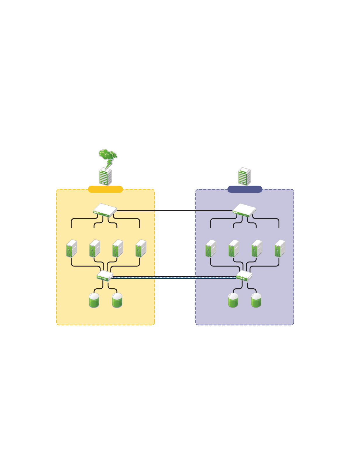
Active Site/Passive Site: A primary site in which all services are normally active, and a
Cluster Site 2Cluster Site 1
Fibre Channel
Switch
Fibre Channel
Disk Arrays
Building A Building B
Ethernet Switch
Fibre Channel
Switch
Fibre Channel
Disk Arrays
Disk blocks
Ethernet Switch
WAN
eDirectory
IDM
Two independent clusters at
geographically separate sites
SAN
Server2BServer
3B
Server
1B
Server
4B
Server2AServer
3A
Server
1A
Server
4A
secondary site which is effectively idle. The data is mirrored to the secondary site, and the
applications and services are ready to load if needed.
The active/active deployment option is typically used in a company that has more than one large site
of operations. The active/passive deployment option is typically used when the purpose of the
secondary site is primarily testing by the IT department. Replication of data blocks is typically done
by SAN hardware, but it can be done by host-based mirroring for synchronous replication over short
distances up to 10 km.
Figure 1-3 shows a two-site business continuity cluster that uses storage-based data replication
between the sites. BCC uses eDirectory and Identity Manager to synchronize cluster information
between the two clusters.
Figure 1-3 Two-Site Business Continuity Cluster
novdocx (en) 7 January 2010
1.4.2 Multiple-Site Business Continuity Cluster Solution
The multiple-site business continuity cluster is a large solution capable of supporting up to four
sites. Each cluster can support up to 32 nodes. Services and applications can do fan-out failover
between sites. Replication of data blocks is typically done by SAN hardware, but it can be done by
host-based mirroring for synchronous replication over short distances up to 10 km.
22 BCC 1.2: Administration Guide for OES 2 SP1 Linux
Page 23
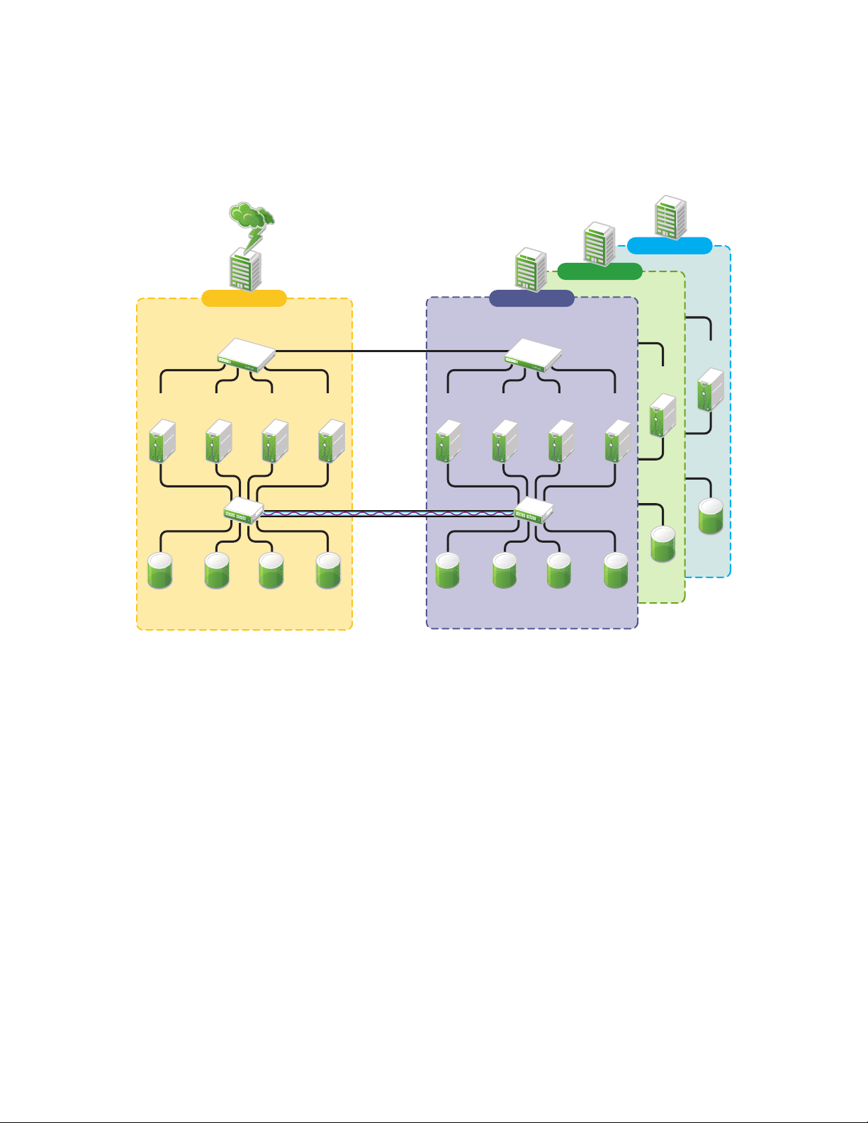
Figure 1-4 depicts a four-site business continuity cluster that uses storage-based data replication
Channel
Channel
Building A
Server
2A
Ethernet Switch
Server
3A
Server
1A
Server
4A
Fibre Channel
Switch
Disk blocks
WAN
eDirectory
IDM
Four independent clusters in
geographically separate sites
Cluster Sites 2, 3, and 4
SAN
Cluster Site 1
Fibre Channel
Disk Arrays
Server
4D
Building D
Server
4C
Building C
Server2BServer
3B
Server
1B
Server
4B
Fibre Channel
Switch
Fibre Channel
Disk Arrays
Ethernet Switch
Building B
between the sites. BCC uses eDirectory and Identity Manager to synchronize cluster information
between the two clusters.
Figure 1-4 Four-Site Business Continuity Cluster
novdocx (en) 7 January 2010
Using additional software, all services, applications, and data can be rendered through the Internet,
allowing for loss of service at one site but still providing full access to the services and data by virtue
of the ubiquity of the Internet. Data and services continue to be available from the other mirrored
sites. Moving applications and services to the Internet frees corporations from the restrictions of
traditional LAN-based applications. Traditional LAN applications require a LAN infrastructure that
must be replicated at each site, and might require relocation of employees to allow the business to
continue. Internet-based applications allow employees to work from any place that offers an Internet
connection, including homes and hotels.
1.4.3 Low-Cost Business Continuity Cluster Solution
The low-cost business continuity cluster solution is similar to the previous two solutions, but
replaces Fibre Channel storage arrays with iSCSI storage arrays. Data block mirroring can be
accomplished either with iSCSI-based block replication, or host-based mirroring. In either case,
snapshot technology can allow for asynchronous replication over long distances. However, the lowcost solution does not necessarily have the performance associated with higher-end Fibre Channel
storage arrays.
Overview of Business Continuity Clustering 23
Page 24

1.5 Key Concepts
The key concepts in this section can help you understand how Business Continuity Clustering
manages your business continuity cluster.
Section 1.5.1, “Business Continuity Clusters,” on page 24
Section 1.5.2, “Cluster Resources,” on page 24
Section 1.5.3, “Landing Zone,” on page 24
Section 1.5.4, “BCC Drivers for Identity Manager,” on page 24
1.5.1 Business Continuity Clusters
A cluster of two to four Novell Cluster Services clusters that are managed together by Business
Continuity Clustering software. All nodes in every peer cluster are running the same operating
system.
1.5.2 Cluster Resources
novdocx (en) 7 January 2010
A cluster resource is a cluster-enabled shared disk that is configured for Novell Cluster Services. It
is also BCC-enabled so that it can be migrated and failed over between nodes in different peer
clusters.
1.5.3 Landing Zone
The landing zone is an eDirectory context in which the objects for the Virtual Server, the Cluster
Pool, and the Cluster Volume are placed when they are created for the peer clusters. You specify the
landing zone context when you configure the Identity Manager drivers for the business continuity
cluster.
1.5.4 BCC Drivers for Identity Manager
Business Continuity Clustering requires a special Identity Manager driver that uses an Identity Vault
to synchronize the cluster resource configuration information between the peer clusters. If the peer
clusters are in different eDirectory trees, an additional BCC driver helps synchronize user
information between the trees. For information, see Chapter 8, “Configuring the Identity Manager
Drivers for BCC,” on page 67.
24 BCC 1.2: Administration Guide for OES 2 SP1 Linux
Page 25

2
What’s New for BCC 1.2
This section describes the changes and enhancements that were made to Novell® Business
Continuity Clustering (BCC) 1.2 for Novell Open Enterprise Server (OES) 2 Support Pack 1 (SP1)
since the initial release of BCC 1.2.
Section 2.1, “BCC 1.2.0 Patch (January 2010),” on page 25
Section 2.2, “Identity Manager 3.6.1 Support (June 2009),” on page 26
Section 2.3, “BCC 1.2 for OES 2 SP1 Linux,” on page 26
2.1 BCC 1.2.0 Patch (January 2010)
In January 2010, a BCC 1.2.0 patch is available through the OES 2 SP1 Linux patch channel
(oes2sp1-January-2010-Scheduled-Maintenance-6749). For information about applying the patch,
see Chapter 5, “Updating (Patching) BCC 1.2.0 on OES 2 SP1 Linux,” on page 57.
novdocx (en) 7 January 2010
2
The major changes for BCC 1.2.0 are described in the following sections:
Section 2.1.1, “BCC Engine,” on page 25
Section 2.1.2, “BCC Resource Driver Template for Identity Manager,” on page 25
2.1.1 BCC Engine
The BCC 1.2.0 patch includes the following major bug fixes for the BCC engine:
Improves the update process to wait for the
before running the BCC install scripts. (Bug 561055)
Modified the
Typically, the wait is less than 10 seconds.
Modified the post-install script of the Novell BCC specification file to wait up to 5
seconds when
Improves memory management functions that might cause the
the code was simplified and clarified so that the shared memory functions now do exactly what
their names describe. The
keys are not in use by other processes, then to use the verified unique keys for its processing
threads. (Bug 553527)
Improves the detection and handling of
not caught and handled where it occurs, the engine’s main thread detects the exception and
gracefully shuts itself down. (Bug 428161)
novell-bcc init.d
adminfsd
is stopped. Typically, the wait is about 1 second.
bccd
daemon was modified to generate unique keys to verify that the
adminfsd
script to wait up to 15 seconds when
No Memory
and
bccd
daemons to gracefully stop
bccd
daemon to die. Overall,
exceptions. In addition, if an exception is
bccd
is stopped.
2.1.2 BCC Resource Driver Template for Identity Manager
The BCC 1.2.0 patch for OES 2 SP1 Linux includes a new BCC resource driver template for
Identity Manager that offers the following new feature and bug fixes:
Uses a newer policy linking format so that you are no longer prompted to update the driver in
iManager. (New)
What’s New for BCC 1.2
25
Page 26

Adds the host resource name and Novell Distributed File Services (DFS) GUID attributes to
the Volume objects that are synchronized for a BCC-enabled volume resource. (Bug 535127)
No longer creates duplicate NCP Server, Volume, and Pool objects when the landing zone is
not the same location as the cluster server’s container. (Found while debugging Bug 537981)
Ensures that a volume resource’s link to the virtual NCP Server object is updated to point to the
cluster where the resource is mounted. (Found while debugging Bug 537981)
novdocx (en) 7 January 2010
The event for the
IsClusterEnabled
policy in a BCC resource driver now allows a resource’s
peer list to be synchronized to the peer clusters, even if the cluster is disabled, if the current
cluster’s name is being removed from the peer list. Only this specific change is allowed; other
changes to a resource are dropped (vetoed) by the driver after a cluster is disabled. (Bug
434243)
The new BCC resource driver template is compatible with the following combinations of Identity
Manager and operating systems:
Identity Manager Operating System
Identity Manager 3.6 (32-bit) OES 2 SP1 Linux (32-bit)
Identity Manager 3.6.1 (32-bit or 64-bit) OES 2 SP1 Linux (32-bit or 64-bit)
Identity Manager 3.6.1 (32-bit or 64-bit) OES 2 SP2 Linux (32-bit or 64-bit)
Identity Manager 3.5.x NetWare
®
6.5 SP8
The new BCC resource driver template is not automatically applied to existing drivers. You can
continue to use your existing BCC resource drivers, or you can re-create the BCC resource drivers
with the new template in order to take advantage of the changes it offers. We recommend that you
re-create the drivers with the new template, but it is not required.
2.2 Identity Manager 3.6.1 Support (June 2009)
In June 2009, Identity Manager 3.6.1 was released to provide support for the 64-bit OES 2 SP1
Linux operating system. Previously, Identity Manager required a 32-bit operating system, even with
64-bit hardware. This means the Identity Manager node in a BCC peer cluster can now be installed
on a 64-bit operating system. Updating to Identity Manager 3.6.1 is needed only for 64-bit support,
or to take advantage of bug fixes that might be offered in 3.6.1.
For information about upgrading from Identity Manager 3.6 to Identity Manager 3.6.1 in a BCC
environment, see Chapter 6, “Upgrading the Identity Manager Nodes to Identity Manager 3.6.1,” on
page 61.
2.3 BCC 1.2 for OES 2 SP1 Linux
BCC 1.2 for OES 2 SP1 Linux provides the following enhancements and changes over BCC 1.1 SP2
for NetWare
Support for OES 2 SP1 Linux
Support for Novell Cluster Services
Support for Identity Manager 3.6 (32-bit). A 64-bit update is planned.
Support for 32-bit and 64-bit architectures
26 BCC 1.2: Administration Guide for OES 2 SP1 Linux
®
6.5 SP8:
TM
1.8.6 for Linux
Page 27

novdocx (en) 7 January 2010
Support for Novell eDirectory
TM
8.8
Support for Novell iManager 2.7.2
Preferred node failover between clusters
Enterprise data center capabilities
Geographical failover of virtual machines as cluster resources
Full support for CIM management in tools (requires OpenWBEM)
What’s New for BCC 1.2 27
Page 28

novdocx (en) 7 January 2010
28 BCC 1.2: Administration Guide for OES 2 SP1 Linux
Page 29

3
Planning a Business Continuity
novdocx (en) 7 January 2010
Cluster
Use the guidelines in this section to design your Novell® Business Continuity Clustering solution.
The success of your business continuity cluster depends on the stability and robustness of the
individual peer clusters. BCC cannot overcome weaknesses in a poorly designed cluster
environment.
Section 3.1, “Determining Design Criteria,” on page 29
Section 3.2, “Best Practices,” on page 29
Section 3.3, “LAN Connectivity Guidelines,” on page 30
Section 3.4, “SAN Connectivity Guidelines,” on page 31
Section 3.5, “Storage Design Guidelines,” on page 32
Section 3.6, “eDirectory Design Guidelines,” on page 32
Section 3.7, “Cluster Design Guidelines,” on page 34
3.1 Determining Design Criteria
The design goal for your business continuity cluster is to ensure that your critical data and services
can continue in the event of a disaster. Design the infrastructure based on your business needs.
3
Determine your design criteria by asking and answering the following questions:
What are the key services that drive your business?
Where are your major business sites, and how many are there?
What services are essential for business continuance?
What is the cost of down time for the essential services?
Based on their mission-critical nature and cost of down time, what services are the highest
priority for business continuance?
Where are the highest-priority services currently located?
Where should the highest-priority services be located for business continuance?
What data must be replicated to support the highest-priority services?
How much data is involved, and how important is it?
3.2 Best Practices
The following practices help you avoid potential problems with your BCC:
IP address changes should always be made on the Protocols page of the iManager cluster plug-
in, not in load and unload scripts.
TM
This is the only way to change the IP address on the virtual NCP
eDirectory
TM
.
server object in
Planning a Business Continuity Cluster
29
Page 30

Ensure that eDirectory and your clusters are stable before implementing BCC.
Engage Novell Consulting.
Engage a consulting group from your SAN vendor.
The cluster node that hosts the Identity Manager driver should have a full read/write
eDirectory
Driver set container
Cluster container
(Parent) container where the servers reside
Landing zone container
User object container
Ensure that you have full read/write replicas of the entire tree at each data center.
TM
replica with the following containers in the replica:
3.3 LAN Connectivity Guidelines
The primary objective of LAN connectivity in a cluster is to provide uninterrupted heartbeat
communications. Use the guidelines in this section to design the LAN connectivity for each of the
peer clusters in the business continuity cluster:
novdocx (en) 7 January 2010
Section 3.3.1, “VLAN,” on page 30
Section 3.3.2, “Channel Bonding,” on page 30
Section 3.3.3, “IP Addresses,” on page 31
Section 3.3.4, “Name Resolution,” on page 31
Section 3.3.5, “IP Addresses for BCC-Enabled Cluster Resources,” on page 31
3.3.1 VLAN
Use a dedicated VLAN (virtual local area network) for each cluster.
The cluster protocol is non-routable, so you cannot direct communications to specific IP addresses.
Using a VLAN for the cluster nodes provides a protected environment for the heartbeat process and
ensures that heartbeat packets are exchanged only between the nodes of a given cluster.
When using a VLAN, no foreign host can interfere with the heartbeat. For example, it avoids
broadcast storms that slow traffic and result in false split-brain abends.
3.3.2 Channel Bonding
Use channel bonding for adapters for LAN fault tolerance. Channel bonding combines Ethernet
interfaces on a host computer for redundancy or increased throughput. It helps increase the
availability of an individual cluster node, which helps avoid or reduce the occurrences of failover
caused by slow LAN traffic. For information, see
bonding.txt
.
/usr/src/linux/Documentation/
When configuring Spanning Tree Protocol (STP), ensure that Portfast is enabled, or consider Rapid
Spanning Tree. The default settings for STP inhibit the heartbeat for over 30 seconds whenever there
is a change in link status. Test your STP configuration with Novell Cluster Services
make sure that a node is not cast out of the cluster when a broken link is restored.
30 BCC 1.2: Administration Guide for OES 2 SP1 Linux
TM
running to
Page 31

Consider connecting cluster nodes to access switches for fault tolerance.
3.3.3 IP Addresses
Use a dedicated IP address range for each cluster. You need a unique static IP address for each of the
following components of each peer cluster:
Cluster (master IP address)
Cluster nodes
Cluster resources that are not BCC-enabled (file system resources and service resources such as
DHCP, DNS, SLP, FTP, and so on)
Cluster resources that are BCC-enabled (file system resources and service resources such as
DHCP, DNS, SLP, FTP, and so on)
Plan your IP address assignment so that it is consistently applied across all peer clusters. Provide an
IP address range with sufficient addresses for each cluster.
3.3.4 Name Resolution
novdocx (en) 7 January 2010
In BCC 1.1 and later, the master IP addresses are stored in the NCS:BCC Peers attribute. Ensure that
SLP is properly configured for name resolution.
3.3.5 IP Addresses for BCC-Enabled Cluster Resources
Use dedicated IP address ranges for BCC-enabled cluster resources. With careful planning, the IP
address and the name of the virtual server for the cluster resource never need to change.
The IP address of an inbound cluster resource is transformed to use an IP address in the same subnet
of the peer cluster where it is being cluster migrated. You define the transformation rules to
accomplish this by using the Identity Manager driver’s search and replace functionality. The
transformation rules are easier to define and remember when you use strict IP address assignment,
such as using the third octet to identify the subnet of the peer cluster.
For an example of configuring a dynamic transformation by using DNS, see Appendix E, “Using
Dynamic DNS with BCC 1.2,” on page 149.
3.4 SAN Connectivity Guidelines
The primary objective of SAN (storage area network) connectivity in a cluster is to provide solid
and stable connectivity between cluster nodes and the storage system. Before installing Novell
Cluster Services and Novell Business Continuity Clustering, make sure the SAN configuration is
established and verified.
Use the guidelines in this section to design the SAN connectivity for each of the peer clusters in the
business continuity cluster:
Use host-based multipath I/O management.
Use redundant SAN connections to provide fault-tolerant connectivity between the cluster
nodes and the shared storage devices.
Connect each node via two fabrics to the storage environment.
Planning a Business Continuity Cluster 31
Page 32

Use a minimum of two mirror connections between storage environments over different fabrics
and wide area networks.
Make sure the distance between storage subsystems is within the limitations of the fabric used
given the amount of data, how the data is mirrored, and how long applications can wait for
acknowledgement. Also make sure to consider support for asynchronous versus synchronous
connections.
3.5 Storage Design Guidelines
Use the guidelines in this section to design the shared storage solution for each of the peer clusters in
the business continuity cluster.
Use a LUN device as the failover unit for each BCC-enabled cluster resource. Multiple pools
per LUN are possible, but are not recommended. A LUN cannot be concurrently accessed by
servers belonging to different clusters. This means that all resources on a given LUN can be
active in a given cluster at any given time. For maximum flexibility, we recommend that you
create only one cluster resource per LUN.
We recommend that you use only one LUN per pool, and only one volume per pool. If you use
multiple LUNs for a given shared NSS pool, all LUNs must fail over together.
Data must be mirrored between data centers by using host-based mirroring or storage-based
mirroring. Storage-based mirroring is recommended.
novdocx (en) 7 January 2010
When using host-based mirroring, make sure that the mirrored partitions are accessible for the
nodes of only one of the BCC peer clusters at any given time. If you use multiple LUNs for a
given pool, each segment must be mirrored individually. In large environments, it might be
difficult to determine the mirror state of all mirrored partitions at one time. You must also make
sure that all segments of the resource fail over together.
3.6 eDirectory Design Guidelines
Your Novell eDirectory solution for each of the peer clusters in the business continuity cluster must
consider the following configuration elements. Make sure your approach is consistent across all peer
clusters.
Section 3.6.1, “Object Location,” on page 32
Section 3.6.2, “Cluster Context,” on page 33
Section 3.6.3, “Partitioning and Replication,” on page 33
Section 3.6.4, “Objects Created by the BCC Drivers for Identity Manager,” on page 33
Section 3.6.5, “Landing Zone,” on page 33
Section 3.6.6, “Naming Conventions for BCC-Enabled Resources,” on page 34
3.6.1 Object Location
Cluster nodes and Cluster objects can exist anywhere in the eDirectory tree. The virtual server
object, cluster pool object, and cluster volume object are automatically created in the eDirectory
context of the server where the cluster resource is created and cluster-enabled. You should create
cluster resources on the master node of the cluster.
32 BCC 1.2: Administration Guide for OES 2 SP1 Linux
Page 33

3.6.2 Cluster Context
Place each cluster in a separate Organizational Unit (OU). All server objects and cluster objects for a
given cluster should be in the same OU.
Figure 3-1 Cluster Resources in Separate OUs
novdocx (en) 7 January 2010
3.6.3 Partitioning and Replication
Partition the cluster OU and replicate it to dedicated eDirectory servers holding a replica of the
parent partition and to all cluster nodes. This helps prevent resources from being stuck in an NDS
Sync state when a cluster resource’s configuration is modified.
®
3.6.4 Objects Created by the BCC Drivers for Identity Manager
When a resource is BCC-enabled, its configuration is automatically synchronized with every peer
cluster in the business continuity cluster by using customized Identity Manager drivers. The
following eDirectory objects are created in each peer cluster:
Cluster Resource object
Virtual Server object
Cluster Pool object
Cluster Volume object
The Cluster Resource object is placed in the Cluster object of the peer clusters where the resource
did not exist initially. The Virtual Server, Cluster Pool, and Cluster Volume objects are stored in the
landing zone. Search-and-replace transform rules define cluster-specific modifications such as the
IP address.
3.6.5 Landing Zone
Any OU can be defined as the BCC landing zone. Use a separate OU for the landing zone than you
use for a cluster OU. The cluster OU for one peer cluster can be the landing zone OU for a different
peer cluster.
Planning a Business Continuity Cluster 33
Page 34

3.6.6 Naming Conventions for BCC-Enabled Resources
Develop a cluster-independent naming convention for BCC-enabled cluster resources. It can
become confusing if the cluster resource name refers to one cluster and is failed over to a peer
cluster.
You can use a naming convention for resources in your BCC as you create those resources.
Changing existing names of cluster resources is less straightforward and can be error prone.
For example, when cluster-enabling NSS pools the default naming conventions used by NSS are:
novdocx (en) 7 January 2010
Cluster Resource:
Cluster-Enabled Pool:
Cluster-Enabled Volume:
Virtual Server:
poolname_SERVER
clustername_poolname_POOL
clustername_volumename
clustername_poolname_SERVER
Instead, use names that are independent of the clusters and that are unique across all peer clusters.
For example, replace the clustername with something static such as BCC.
Cluster Resource:
Cluster-Enabled Pool:
Cluster-Enabled Volume:
Virtual Server:
poolname_SERVER
BCC_poolname_POOL
BCC_volumename
BCC_poolname_SERVER
Resources have an identity in each peer cluster, and the names are the same in each peer cluster. For
example, Figure 3-2 shows the cluster resource identity in each of two peer clusters.
Figure 3-2 Cluster Resource Identity in Two Clusters
3.7 Cluster Design Guidelines
Your Novell Cluster Services solution for each of the peer clusters in the business continuity cluster
must consider the following configuration guidelines. Make sure your approach is consistent across
all peer clusters.
IP address assignments should be consistently applied within each peer cluster and for all
cluster resources.
Ensure that IP addresses are unique across all BCC peer clusters.
34 BCC 1.2: Administration Guide for OES 2 SP1 Linux
Page 35

Volume IDs must be unique across all peer clusters. Each cluster node automatically assigns
SYS
volume ID 0 to volume
and volume ID 1 to volume
_ADMIN
. Cluster-enabled volumes use
high volume IDs, starting from 254 in descending order. Novell Client uses the volume ID to
access a volume.
When existing clusters are configured and enabled within the same business continuity cluster,
the volume IDs for the existing shared volumes might also share the same volume IDs. To
resolve this conflict, manually edit the load script for each volume that has been enabled for
business continuity and change the volume IDs to unique values for each volume in the
business continuity cluster.
BCC configuration should consider the configuration requirements for each of the services
supported across all peer clusters.
Create failover matrixes for each cluster resource so that you know what service is supported
and which nodes are the preferred nodes for failover within the same cluster and among the
peer clusters.
novdocx (en) 7 January 2010
Planning a Business Continuity Cluster 35
Page 36

novdocx (en) 7 January 2010
36 BCC 1.2: Administration Guide for OES 2 SP1 Linux
Page 37

4
Installing Business Continuity
novdocx (en) 7 January 2010
Clustering
This section describes how to install, set up, and configure Novell® Business Continuity Clustering
1.2 for Novell Open Enterprise Server (OES) 2 SP1 Linux for your specific needs.
Section 4.1, “Requirements for BCC 1.2 for OES 2 SP1 Linux,” on page 37
Section 4.2, “Downloading the Business Continuity Clustering Software,” on page 48
Section 4.3, “Configuring a BCC Administrator User and Group,” on page 48
Section 4.4, “Installing and Configuring the Novell Business Continuity Clustering Software,”
on page 50
Section 4.5, “Using a YaST Auto-Configuration File to Install and Configure Business
Continuity Clustering Software,” on page 53
Section 4.6, “What’s Next,” on page 56
4.1 Requirements for BCC 1.2 for OES 2 SP1 Linux
The requirements in this section must be met prior to installing Novell Business Continuity
Clustering 1.2 for Linux software.
4
Section 4.1.1, “Business Continuity Clustering License,” on page 38
Section 4.1.2, “Business Continuity Cluster Component Locations,” on page 38
Section 4.1.3, “OES 2 SP1 Linux,” on page 39
Section 4.1.4, “Novell Cluster Services 1.8.6 for Linux,” on page 39
Section 4.1.5, “Novell eDirectory 8.8,” on page 40
Section 4.1.6, “SLP,” on page 42
Section 4.1.7, “Identity Manager 3.6 Bundle Edition,” on page 42
Section 4.1.8, “Novell iManager 2.7.2,” on page 44
Section 4.1.9, “Storage-Related Plug-Ins for iManager 2.7.2,” on page 44
Section 4.1.10, “OpenWBEM,” on page 45
Section 4.1.11, “Shared Disk Systems,” on page 45
Section 4.1.12, “Mirroring Shared Disk Systems Between Peer Clusters,” on page 46
Section 4.1.13, “LUN Masking for Shared Devices,” on page 46
Section 4.1.14, “Link Speeds,” on page 46
Section 4.1.15, “Ports,” on page 47
Section 4.1.16, “Web Browser,” on page 47
Installing Business Continuity Clustering
37
Page 38

4.1.1 Business Continuity Clustering License
Building A
Fibre Channel
Switch
Fibre Channel
Disk Arrays
Cluster Site 1
Server
1A
Server
2A
Server
A
Server
3A
NCS
BCC eng.
OES Linux
NCS
BCC eng.
OES Linux
iManager
OES Linux
NCS
BCC eng.
OES Linux
IDM eng.
Ethernet Switch
IDM
Management
Utilities
BCC
iManager
plug-ins
WAN
eDirectory
IDM
Disk blocks
SAN
IDM eDir
Driver
Fibre Channel
Switch
Fibre Channel
Disk Arrays
Building B
Cluster Site 2
Server
1B
Server
2B
Server
3B
Server
B
OES Linux
IDM
Management
Utilities
BCC
iManager
plug-ins
iManager
Ethernet Switch
NCS
BCC eng.
OES Linux
NCS
BCC eng.
OES Linux
IDM eng.
IDM eDir
Driver
NCS
BCC eng.
OES Linux
Novell Business Continuity Clustering software requires a license agreement for each business
continuity cluster. For purchasing information, see Novell Business Continuity Clustering (http://
www.novell.com/products/businesscontinuity/howtobuy.html).
4.1.2 Business Continuity Cluster Component Locations
Figure 4-1 illustrates where the various components needed for a business continuity cluster are
installed.
Figure 4-1 Business Continuity Cluster Component Locations
novdocx (en) 7 January 2010
38 BCC 1.2: Administration Guide for OES 2 SP1 Linux
Figure 4-1 uses the following abbreviations:
BCC: Novell Business Continuity Clustering 1.2 for Linux
eDir: Novell eDirectory 8.8
IDM: Identity Manager 3.6.x
iManager: Novell iManager 2.7.2
NCS: Novell Cluster Services 1.8.6 for Linux
OES Linux: Novell Open Enterprise Server 2 SP1 for Linux
Page 39

4.1.3 OES 2 SP1 Linux
Novell Open Enterprise Server (OES) 2 Support Pack 1 (SP1) for Linux must be installed and
running on every node in each peer cluster that will be part of the business continuity cluster.
See the OES 2 SP1: Linux Installation Guide (http://www.novell.com/documentation/oes2/
inst_oes_lx/data/front.html) for information on installing and configuring OES 2 SP1 Linux.
IMPORTANT: If you use Identity Manager 3.6, each node in every peer cluster where Identity
Manager 3.6 is installed must be running the 32-bit version of OES 2 SP1 Linux because Identity
Manager 3.6 supports only 32-bit operating systems. Identity Manager 3.6.1 supports the 64-bit
version of OES 2 SP1 Linux.
4.1.4 Novell Cluster Services 1.8.6 for Linux
You need two to four clusters with Novell Cluster ServicesTM 1.8.6 (the version that ships with OES
2 SP1) installed and running on each node in the cluster.
See the OES 2 SP1: Novell Cluster Services 1.8.6 for Linux Administration Guide for information on
installing, configuring, and managing Novell Cluster Services.
novdocx (en) 7 January 2010
Consider the following when preparing your clusters for the business continuity cluster:
“Cluster Names” on page 39
“Storage” on page 39
“eDirectory” on page 40
“Peer Cluster Credentials” on page 40
Cluster Names
Each cluster must have a unique name, even if the clusters reside in different Novell eDirectory
TM
trees. Clusters must not have the same name as any of the eDirectory trees in the business continuity
cluster.
Storage
The storage requirements for Novell Business Continuity Clustering software are the same as for
Novell Cluster Services. For more information, see the following in the OES 2 SP1: Novell Cluster
Services 1.8.6 for Linux Administration Guide:
“Hardware Requirements”
“Shared Disk System Requirements”
“LUN Masking”
Some storage vendors require you to purchase or license their CLI (Command Line Interface)
separately. The CLI for the storage system might not initially be included with your hardware.
Also, some storage hardware may not be SMI-S compliant and cannot be managed by using SMI-S
commands.
Installing Business Continuity Clustering 39
Page 40

eDirectory
The recommended configuration is to have each cluster in the same eDirectory tree but in different
OUs (Organizational Units). BCC 1.2 for Linux supports only a single-tree setup.
Peer Cluster Credentials
To add or change peer cluster credentials, you must access iManager on a server that is in the same
eDirectory tree as the cluster where you are adding or changing peer credentials.
4.1.5 Novell eDirectory 8.8
Novell eDirectory 8.8 is supported with Business Continuity Clustering 1.2. See the eDirectory 8.8
documentation (http://www.novell.com/documentation/edir88/index.html) for more information.
“eDirectory Containers for Clusters” on page 40
“Rights Needed for Installing BCC” on page 40
“Rights Needed for Individual Cluster Management” on page 41
“Rights Needed for BCC Management” on page 41
“Rights Needed for Identity Manager” on page 41
novdocx (en) 7 January 2010
eDirectory Containers for Clusters
Each of the clusters that you want to add to a business continuity cluster should reside in its own OU
level container. Each OU should reside in a different eDirectory partition.
As a best practice for each of the peer clusters, put its Server objects, Cluster object, Driver objects,
and Landing Zone in a the same eDirectory partition.
For example:
ou=cluster1 ou=cluster2 ou=cluster3
ou=cluster1LandingZone ou=cluster2LandingZone ou=cluster3LandingZone
cn=cluster1 cn=cluster2 cn=cluster3
c1server35
c1server36
c1server37 (IDM node with read/
write access to ou=cluster1)
cluster1BCCDrivers
c1toc2BCCDriver
c2server135
c2server136
c3server137 (IDM node with
read/write access to ou=cluster2)
cluster2BCCDrivers
c2toc1BCCDriver
c3server235
c3server236
c3server237 (IDM node with
read/write access to ou=cluster3)
cluster3BCCDrivers
c3toc1BCCDriver
c1toc3BCCDriver
Rights Needed for Installing BCC
The first time that you install the Business Continuity Clustering engine software in an eDirectory
tree, the eDirectory schema is automatically extended with BCC objects.
40 BCC 1.2: Administration Guide for OES 2 SP1 Linux
Page 41

IMPORTANT: The user who installs BCC must have the eDirectory credentials necessary to
extend the schema.
If the eDirectory administrator username or password contains special characters (such as $, #, and
so on), you might need to escape each special character by preceding it with a backslash (\) when
you enter credentials for some interfaces.
Rights Needed for Individual Cluster Management
The BCC Administrator user is not automatically assigned the rights necessary to manage all aspects
of each peer cluster. When managing individual clusters, you must log in as the Cluster
Administrator user. You can manually assign the Cluster Administrator rights to the BCC
Administrator user for each of the peer clusters if you want the BCC Administrator user to have all
rights.
Rights Needed for BCC Management
Before you install BCC, create the BCC Administrator user and group identities in eDirectory to use
when you manage the BCC. For information, see Section 4.3, “Configuring a BCC Administrator
User and Group,” on page 48.
novdocx (en) 7 January 2010
Rights Needed for Identity Manager
The node where Identity Manager is installed must have an eDirectory full replica with at least read/
write access to all eDirectory objects that will be synchronized between clusters. You can also have
the eDirectory master running on the node instead of the replica.
The replica does not need to contain all eDirectory objects in the tree. The eDirectory full replica
must have at least read/write access to the following containers in order for the cluster resource
synchronization and user object synchronization to work properly:
The Identity Manager driver set container.
The container where the Cluster object resides.
The container where the Server objects reside.
If Server objects reside in multiple containers, this must be a container high enough in the tree
to be above all containers that contain Server objects.
The best practice is to have all Server objects in one container.
The container where the cluster Pool objects and Volume objects are placed when they are
synchronized to this cluster. This container is referred to as the landing zone. The NCP
TM
Server
objects for the virtual server of a BCC-enabled resource are also placed in the landing zone.
The container where the User objects reside that need to be synchronized. Typically, the User
objects container is in the same partition as the cluster objects.
IMPORTANT: Full eDirectory replicas are required. Filtered eDirectory replicas are not supported
with this version of Business Continuity Clustering software.
Installing Business Continuity Clustering 41
Page 42

4.1.6 SLP
You must have SLP (Server Location Protocol) set up and configured properly on each server node
in every cluster. Typically, SLP is installed as part of the eDirectory installation and setup when you
install the server operating system for the server. For information, see “Implementing the Service
Location Protocol” (http://www.novell.com/documentation/edir88/edir88/data/ba5lb4b.html) in the
Novell eDirectory 8.8 Administration Guide.
4.1.7 Identity Manager 3.6 Bundle Edition
The Identity Manager 3.6 Bundle Edition is required for synchronizing the configuration of the peer
clusters in your business continuity cluster. It is not involved in other BCC management operations
such as migrating cluster resources within or across peer clusters.
Beginning in June 2009, Identity Manager 3.6.1 is also supported for BCC 1.2 on OES 2 SP1 Linux.
For information about upgrading to 3.6.1 in an existing BCC environment, see Chapter 6,
“Upgrading the Identity Manager Nodes to Identity Manager 3.6.1,” on page 61.
Before you install Business Continuity Clustering on the cluster nodes, make sure that Identity
Manager and the Identity Manager driver for eDirectory are installed on one node in each peer
cluster that you want to be part of the business continuity cluster.
novdocx (en) 7 January 2010
The same Identity Manager installation program that is used to install the Identity Manager engine is
also used to install the Identity Manager eDirectory driver and management utilities. See “Business
Continuity Cluster Component Locations” on page 38 for information on where to install Identity
Manager components.
“Downloading the Bundle Edition” on page 42
“Credential for Drivers” on page 43
“Identity Manager Engine and eDirectory Driver” on page 43
“Identity Manager Driver for eDirectory” on page 43
“Identity Manager Management Utilities” on page 43
Downloading the Bundle Edition
The bundle edition is a limited release of Identity Manager 3.6 or 3.6.1 for OES 2 SP1 Linux that
allows you to use the Identity Manager software, the eDirectory driver, and the Identity Manager
management tools for Novell iManager 2.7.2. BCC driver templates are applied to the eDirectory
driver to create BCC-specific drivers that automatically synchronize BCC configuration information
between the Identity Manager nodes in peer clusters.
To download Identity Manager, go to to the Novell Downloads Web site (http://www.novell.com/
downloads/).
IMPORTANT: Identity Manger 3.6 requires a 32-bit OES 2 SP1 Linux operating system, even on
64-bit hardware. Identity Manager 3.6.1 additionally supports the 64-bit OES 2 SP1 Linux operating
system.
42 BCC 1.2: Administration Guide for OES 2 SP1 Linux
Page 43

Credential for Drivers
The Bundle Edition requires a credential that allows you to use drivers beyond an evaluation period.
The credential can be found in the BCC license. In the Identity Manager interface in iManager, enter
the credential for each driver that you create for BCC. You must also enter the credential for the
matching driver that is installed in a peer cluster. You can enter the credential, or put the credential in
a file that you point to.
Identity Manager Engine and eDirectory Driver
novdocx (en) 7 January 2010
BCC requires Identity Manager 3.6 or later to run on one node in each of the clusters that belong to
®
the business continuity cluster. (Identity Manager was formerly called DirXML
.) Identity Manager
should not be set up as clustered resource. Each Identity Manager node must be online in its peer
cluster and Identity Manager must be running properly whenever you attempt to modify the BCC
configuration or manage the BCC-enabled cluster resources.
IMPORTANT: Identity Manager 3.6 is 32-bit and is supported only on the 32-bit OES 2 SP1 Linux
operating system, even on 64-bit hardware. Identity Manager 3.6.1 additionally supports the 64-bit
OES 2 SP1 Linux operating system.
For installation instructions, see the Identity Manager 3.6.x Installation Guide (http://
www.novell.com/documentation/idm36/idm_install/data/front.html).
The node where the Identity Manager engine and the eDirectory driver are installed must have an
eDirectory full replica with at least read/write access to all eDirectory objects that will be
synchronized between clusters. This does not apply to all eDirectory objects in the tree. For
information about the eDirectory full replica requirements, see Section 4.1.5, “Novell eDirectory
8.8,” on page 40.
Identity Manager Driver for eDirectory
On the same node where you install the Identity Manager engine, install one instance of the Identity
Manager driver for eDirectory.
For information about installing the Identity Manager driver for eDirectory, see Identity Manager
3.6.x Driver for eDirectory: Implementation Guide (http://www.novell.com/documentation/
idm36drivers/edirectory/data/bktitle.html).
Identity Manager Management Utilities
The Identity Manager management utilities must be installed on the same server as Novell
iManager. The Identity Manager utilities and iManager can be installed on a cluster node, but
installing them on a non-cluster node is the recommended configuration. For information about
iManager requirements for BCC, see Section 4.1.8, “Novell iManager 2.7.2,” on page 44.
IMPORTANT: Identity Manager plug-ins for iManager require that eDirectory is running and
working properly in the tree. If the plug-in does not appear in iManager, make sure that the
ndsd
eDirectory daemon (
To resta r t
prompt as the
rcndsd restart
ndsd
on the master replica server, enter the following command at its terminal console
root
) is running on the server that contains the eDirectory master replica.
user:
Installing Business Continuity Clustering 43
Page 44

4.1.8 Novell iManager 2.7.2
Novell iManager 2.7.2 (the version released with OES 2 SP1 Linux) must be installed and running
on a server in the eDirectory tree where you are installing Business Continuity Clustering software.
You need to install the BCC plug-in, the Clusters plug-in, and the Storage Management plug-in in
order to manage the BCC in iManager. As part of the install process, you must also install plug-ins
for the Identity Manager role that are management templates for configuring a business continuity
cluster. The templates are in the
novellbusiness-continuity-cluster-idm.rpm
For information about installing and using iManager, see the Novell iManager 2.7 documentation
Web site (http://www.novell.com/documentation/imanager27/index.html).
The Identity Manager management utilities must be installed on the same server as iManager. You
can install iManager and the Identity Manager utilities on a cluster node, but installing them on a
non-cluster node is the recommended configuration. For information about Identity Manager
requirements for BCC, see Section 4.1.7, “Identity Manager 3.6 Bundle Edition,” on page 42.
See “Business Continuity Cluster Component Locations” on page 38 for specific information on
where to install Identity Manager components.
module.
novdocx (en) 7 January 2010
4.1.9 Storage-Related Plug-Ins for iManager 2.7.2
The Clusters plug-in (
provide support for this release of Business Continuity Clustering. You must install the Clusters
plug-in and the Storage Management plug-in (
IMPORTANT: The Storage Management plug-in module (
code required by all of the other storage-related plug-ins. Make sure that you include
storagemgmt.npm
you should install, update, or remove them all at the same time to make sure the common code
works for all plug-ins.
Other storage-related plug-ins are Novell Storage Services
afpmgmt.npm
(
and Novell Archive and Version Services (
pools as cluster resources. The other services are optional.
The Novell Storage Related Plug-ins for iManager 2.7x are available as a zipped download file on
the Novell Downloads (http://www.novell.com/downloads) Web site.
To install or upgrade the Clusters plug-in:
1 On the iManager server, if the OES 2 version of the storage-related plug-ins are installed, or if
you upgraded this server from OES 2 Linux or NetWare 6.5 SP7, log in to iManager, then
uninstall all of the storage-related plug-ins that are currently installed, including
storagemgmt.npm
ncsmgmt.npm
) has been updated from the release in OES 2 SP1 Linux to
storagemgmt.npm
).
storagemgmt.npm
) contains common
when installing any of the others. If you use more than one of these plug-ins,
TM
), Novell CIFS (
cifsmgmt.npm
avmgmt.npm
(NSS) (
), Novell Distributed File Services (
). NSS is required in order to use shared NSS
nssmgmt.npm
), Novell AFP
dfsmgmt.npm
.
),
This step is necessary for upgrades only if you did not uninstall and reinstall the storage-related
plug-ins as part of the upgrade process.
2 Copy the new .npm files into the iManager plug-ins location, manually overwriting the older
version of the plug-in in the packages folder with the newer version of the plug-in.
3 In iManager, install all of the storage-related plug-ins, or install the plug-ins you need, plus the
common code.
44 BCC 1.2: Administration Guide for OES 2 SP1 Linux
Page 45

4 Restart Tomcat by entering the following command at a terminal console prompt:
rcnovell-tomcat5 restart
5 Restart Apache by entering the following command at a terminal console prompt.
rcapache2 restart
4.1.10 OpenWBEM
novdocx (en) 7 January 2010
OpenWBEM must be running and configured to start using
chkconfig
. For information, see the
OES 2: OpenWBEM Services Administration Guide (http://www.novell.com/documentation/oes2/
mgmt_openwbem_lx_nw/data/front.html).
The CIMOM daemons on all nodes in the business continuity cluster must be configured to bind to
all IP addresses on the server. For information, see Section 9.5, “Configuring CIMOM Daemons to
Bind to IP Addresses,” on page 88.
Port 5989 is the default setting for secure HTTP (HTTPS) communications. If you are using a
firewall, the port must be opened for CIMOM communications.
Beginning in OES 2, the Clusters plug-in (and all other storage-related plug-ins) for iManager
require CIMOM connections for tasks that transmit sensitive information (such as a username and
password) between iManager and the
_admin
volume on the OES 2 server that you are managing.
Typically, CIMOM is running, so this should be the normal condition when using the server.
CIMOM connections use Secure HTTP (HTTPS) for transferring data, and this ensures that
sensitive data is not exposed.
If CIMOM is not currently running when you click OK or Finish for the task that sends the sensitive
information, you get an error message explaining that the connection is not secure and that CIMOM
must be running before you can perform the task.
IMPORTANT: If you receive file protocol errors, it might be because WBEM is not running.
To check the status of WBEM:
1 Log in as the
rcowcimomd status
root
user in a terminal console, then enter
To start WBEM:
1 Log in as the
rcowcimomd start
root
user in a terminal console, then enter
4.1.11 Shared Disk Systems
For Business Continuity Clustering, a shared disk storage system is required for each peer cluster in
the business continuity cluster. See “Shared Disk System Requirements” in the OES 2 SP1: Novell
Cluster Services 1.8.6 for Linux Administration Guide.
In addition to the shared disks in an original cluster, you need additional shared disk storage in the
other peer clusters to mirror the data between sites as described in Section 4.1.12, “Mirroring Shared
Disk Systems Between Peer Clusters,” on page 46.
Installing Business Continuity Clustering 45
Page 46

4.1.12 Mirroring Shared Disk Systems Between Peer Clusters
The Business Continuity Clustering software does not perform data mirroring. You must separately
configure either storage-based mirroring or host-based file system mirroring for the shared disks that
you want to fail over between peer clusters. Storage-based synchronized mirroring is the preferred
solution.
IMPORTANT: Use whatever method is available to implement storage-based mirroring or hostbased file system mirroring between the peer clusters for each of the shared disks that you plan to
fail over between peer clusters.
For information about how to configure host-based file system mirroring for Novell Storage
Services pool resources, see Appendix C, “Configuring Host-Based File System Mirroring for NSS
Pools,” on page 137.
For information about storage-based mirroring, consult the vendor for your storage system or see the
vendor documentation.
4.1.13 LUN Masking for Shared Devices
novdocx (en) 7 January 2010
LUN masking is the ability to exclusively assign each LUN to one or more host connections. With it,
you can assign appropriately sized pieces of storage from a common storage pool to various servers.
See your storage system vendor documentation for more information on configuring LUN masking.
When you create a Novell Cluster Services system that uses a shared storage system, it is important
to remember that all of the servers that you grant access to the shared device, whether in the cluster
or not, have access to all of the volumes on the shared storage space unless you specifically prevent
such access. Novell Cluster Services arbitrates access to shared volumes for all cluster nodes, but
cannot protect shared volumes from being corrupted by non-cluster servers.
Software included with your storage system can be used to mask LUNs or to provide zoning
configuration of the SAN fabric to prevent shared volumes from being corrupted by non-cluster
servers.
IMPORTANT: We recommend that you implement LUN masking in your business continuity
cluster for data protection. LUN masking is provided by your storage system vendor.
4.1.14 Link Speeds
For real-time mirroring, link latency is the essential consideration. For best performance, the link
speeds should be at least 1 GB per second, and the links should be dedicated.
Many factors should be considered for distances greater than 200 kilometers, some of which
include:
The amount of data being transferred
The bandwidth of the link
Whether or not snapshot technology is being used for data replication
46 BCC 1.2: Administration Guide for OES 2 SP1 Linux
Page 47

4.1.15 Ports
If you are using a firewall, the ports must be opened for OpenWBEM and the Identity Manager
drivers.
Table 4-1 Default Ports for the BCC Setup
Product Default Port
OpenWBEM 5989 (secure)
eDirectory driver 8196
Cluster Resources Synchronization driver 2002 (plus the ports for additional instances)
User Object Synchronization driver 2001 (plus the ports for additional instances)
4.1.16 Web Browser
When using iManager, make sure your Web browser settings meet the requirements in this section.
novdocx (en) 7 January 2010
“Web Browser Language Setting” on page 47
“Web Browser Character Encoding Setting” on page 47
Web Browser Language Setting
The iManager plug-in might not operate properly if the highest priority Language setting for your
Web browser is set to a language other than one of iManager's supported languages. To avoid
problems, in your Web browser, click Tools > Options > Languages, then set the first language
preference in the list to a supported language.
Refer to the Novell iManager documentation (http://www.novell.com/documentation/imanager27/)
for information about supported languages.
Web Browser Character Encoding Setting
Supported language codes are Unicode (UTF-8) compliant. To avoid display problems, make sure
the Character Encoding setting for the browser is set to Unicode (UTF-8) or ISO 8859-1 (Western,
Western European, West European).
In a Mozilla browser, click View > Character Encoding, then select the supported character
encoding setting.
In an Internet Explorer browser, click View > Encoding, then select the supported character
encoding setting.
Installing Business Continuity Clustering 47
Page 48

4.2 Downloading the Business Continuity Clustering Software
Before you install Novell Business Continuity Clustering, download and copy the software to a
directory on your workstation. To download Novell Business Continuity Clustering 1.2 for Linux,
go to the Novell Downloads Web site (http://download.novell.com) and select the Business
Continuity Clustering product.
The Business Continuity Clustering installation program and software is downloaded as an ISO
image. There are a few installation options for using the ISO image on each Linux server that will be
part of the business continuity cluster:
Create a CD from the ISO, mount the CD on the server, and add the CD as a local installation
source.
Copy the ISO to the server and add the ISO as a local installation source.
Copy the ISO file to a location where it can be used for an HTTP installation source.
To use one of these package installation methods, follow the instructions in Section 4.4, “Installing
and Configuring the Novell Business Continuity Clustering Software,” on page 50.
novdocx (en) 7 January 2010
You can also follow the instructions in Section 4.5, “Using a YaST Auto-Configuration File to
Install and Configure Business Continuity Clustering Software,” on page 53 to install from the
network without using a CD or copying the ISO to each server.
4.3 Configuring a BCC Administrator User and Group
During the install, you must specify an existing user to be the BCC Administrator user. This user
should have at least Read and Write rights to the All Attribute Rights property on the Cluster object
of the cluster.
Perform the following tasks to configure the BCC Administrator user and group.
Section 4.3.1, “Creating the BCC Group and Administrative User,” on page 48
Section 4.3.2, “Assigning Trustee Rights for the BCC Administrator User to the Cluster
Objects,” on page 49
Section 4.3.3, “Adding the BCC Administrator User to the ncsgroup on Each Cluster Node,” on
page 49
4.3.1 Creating the BCC Group and Administrative User
For Linux, ensure that the BCC Administrator user is a Linux-enabled user by creating a BCC
Group object (
group by configuring Linux User Management (LUM) for the group. You also add the Linux nodes
(Node objects) of each node in every cluster in the BCC to this BCC group.
bccgroup
), adding the BCC Administrator user to the group, then Linux-enabling the
IMPORTANT: Having a LUM-enabled BCC group and user and adding the Linux cluster nodes to
the BCC group is necessary for inter-cluster communication to function properly.
48 BCC 1.2: Administration Guide for OES 2 SP1 Linux
Page 49

Prior to installing and configuring Business Continuity Clustering software, you must complete the
following tasks:
novdocx (en) 7 January 2010
1 Create a BCC group and name the group, such as
bccgroup
.
IMPORTANT: The name you specify must be in all lowercase.
2 Create a BCC Administrator user (
bccadmin
) and add that user to the BCC group (
bccgroup
before LUM enabling the group.
3 Enable the
Make certain that the you do the following when you LUM-enable
Select LUM enable all users in group option.
Add all Linux nodes (Node objects) in the cluster to the
bccgroup
for Linux by using Linux User Management.
bccgroup
bccgroup
.
:
For information about LUM-enabling groups, see “Managing User and Group Objects in
eDirectory” in the OES 2 SP1: Novell Linux User Management Technology Guide.
LUM-enabling the
bccgroup
automatically enables all users in that group for Linux.
4.3.2 Assigning Trustee Rights for the BCC Administrator User to the Cluster Objects
Assign trustee rights to the BCC Administrator user for each cluster you plan to add to the business
continuity cluster.
1 Start your Internet browser and enter the URL for iManager.
The URL is http://server_ip_address/nps/iManager.html. Replace server_ip_address with the
IP address or DNS name of the Linux server where you have installed iManager and the
Identity Manager preconfigured templates for iManager.
2 Specify your username and password, specify the tree where you want to log in, then click
Login.
3 In Roles and Tasks, click Rights, then click the Modify Trustees link.
4 Specify the Cluster object name, or browse and select it, then click OK.
)
5 If the BCC Administrator user is not listed as a trustee, click the Add Trustee button, browse
and select the User object, then click OK.
6 Click Assigned Rights for the BCC Administrator user, and then ensure the Read and Write
check boxes are selected for the All Attributes Rights property.
7 Click Done to save your changes.
8 Repeat Step 3 through Step 7 for the peer clusters in your business continuity cluster.
4.3.3 Adding the BCC Administrator User to the ncsgroup on Each Cluster Node
In order for the BCC Administrator user to gain access to the cluster administration files (
novell/cluster
Cluster Services administration group (such as
1 Log in as
) on other Linux cluster nodes in your BCC, you must add that user to the Novell
root
and open the
/etc/group
ncsgroup
file.
) on each cluster node.
Installing Business Continuity Clustering 49
/admin/
Page 50

2 Find either of the following lines:
ncsgroup:!:107:
or
ncsgroup:!:107:bccd
The file should contain one of the above lines, but not both.
3 Depending on which line you find, edit the line to read as follows:
ncsgroup:!:107:bccadmin
or
ncsgroup:!:107:bccd,bccadmin
4 Replace bccadmin with the BCC Administrator user you created.
Notice the group ID number of the
actual number is the same on each node in a given cluster; it might be different for each cluster.
ncsgroup
. In this example, the number 107 is used. The
novdocx (en) 7 January 2010
5 After saving the
For example, if you named the BCC Administrator user
The
ncsgroup
/etc/group
should appear as a secondary group of the BCC Administrator user.
file, execute the id command from a shell.
bccadmin
, enter
id bccadmin
.
4.4 Installing and Configuring the Novell Business Continuity Clustering Software
It is necessary to run the Novell Business Continuity Clustering installation program when you want
to:
Install and configure Business Continuity Clustering engine software on the cluster nodes for
the clusters that will be part of a business continuity cluster.
The Business Continuity Clustering for Linux installation installs to only one server at a time.
You must install it on each node of each cluster that you want to be part of a business continuity
cluster.
Install the BCC-specific Identity Manager templates for iManager on an OES 2 Linux server
where you have installed iManager.
The templates add functionality to iManager so you can manage your business continuity
cluster. You must have previously installed iManager on the server where you plan to install the
templates.
Uninstall Business Continuity Clustering software.
IMPORTANT: Before you begin, make sure your setup meets the requirements specified in
Section 4.1, “Requirements for BCC 1.2 for OES 2 SP1 Linux,” on page 37. The BCC
Administrator user and group must already be configured as specified in Section 4.3, “Configuring a
BCC Administrator User and Group,” on page 48.
You must install the Business Continuity Clustering engine software on each cluster node in each of
the peer clusters that will be part of a business continuity cluster. You install the software on the
nodes of one cluster at a time.
50 BCC 1.2: Administration Guide for OES 2 SP1 Linux
Page 51

Perform the following tasks in every peer cluster that you want to include in the business continuity
cluster:
Section 4.4.1, “Installing the Business Continuity Clustering RPMs,” on page 51
Section 4.4.2, “Configuring BCC Software,” on page 52
Section 4.4.3, “Installing the BCC Identity Manager Templates,” on page 52
4.4.1 Installing the Business Continuity Clustering RPMs
Perform the following tasks for each of the nodes in every peer cluster:
novdocx (en) 7 January 2010
1 Log in to the server as the
root
user.
2 Set up the Business Continuity Clustering ISO file as an installation source.
2a Copy the Business Continuity Clustering ISO file that you downloaded in Section 4.2,
“Downloading the Business Continuity Clustering Software,” on page 48 to a local
directory.
If you use a CD or the HTTP method, modify the following steps as needed.
2b Use one of the following methods to open the Add-On Product page.
In YaST, select Software > Installation Source, then click Add.
At a terminal console prompt, enter
yast2 add-on
2c On the Add-On Product Media page, select Local, then click Next.
2d Select ISO Image, then browse to locate and select the file, click Open, then click Next.
2e Read the Business Continuity Clustering License Agreement, click Yes to accept it, then
click Next.
When the installation source is added, it appears in the list on the Add-On Product Media
page.
2f On the Add-Product Media page, click Finish.
The new installation source is synchronized with the Software Updater. The Software
Updater icon in the Notification area indicates that updates are ready.
3 In YaST, select Software > Software Manager, search for BCC, select the three
.rpm
files, then
click Accept to install the packages.
novell-business-continuity-cluster.rpm
novell-business-continuity-cluster-idm.rpm
yast-novell-bcc.rpm
You can also double-click the Software Updater icon in the Notification area, then select the
.rpm
BCC
files.
4 After the packages are installed, exit YaST.
5 Continue with Section 4.4.2, “Configuring BCC Software,” on page 52.
Installing Business Continuity Clustering 51
Page 52

4.4.2 Configuring BCC Software
Perform the following tasks for each of the nodes in every peer cluster:
novdocx (en) 7 January 2010
1 Log in as the
2 Use one of the following methods to open the BCC Configuration page:
In YaST, select Miscellaneous > Novell-BCC.
At a terminal console prompt, enter
yast2 novell-bcc
3 When prompted to Install Core Business Continuity Clustering Software and Configure Core
Software, click Ye s to install and configure the BCC software.
4 Click Continue if you are prompted to configure LDAP.
5 In the eDirectory Tree dialog box, specify the eDirectory Administrator user password that you
used when you installed the operating system, then click OK.
6 Specify the typeful fully distinguished eDirectory name for the cluster where the server is
currently a member.
7 Select Start BCC services now to start the software immediately following the configuration
process.
If you deselect the check box, you must manually start BCC services later by entering the
following at the terminal console prompt:
rcnovell-bcc start
8 Specify the Directory Server Address by selecting the IP addresses of the master eDirectory
server and the local server.
9 Accept or change the eDirectory Administrator user name and specify the Administrator user’s
password.
root
user on the server.
10 Click Next.
11 Review your setup on the Novell Business Continuity Clustering Configuration Summary
page, then click Next to install the BCC software.
12 Click Finish to save the BCC configuration and exit the tool.
13 Verify that the BCC software is running on the server by entering the following at a terminal
console prompt:
rcnovell-bcc status
14 Continue with Section 4.4.3, “Installing the BCC Identity Manager Templates,” on page 52.
4.4.3 Installing the BCC Identity Manager Templates
The Identity Manager management templates for Business Continuity Clustering consist of XML
templates for the eDirectory driver that are used for synchronizing objects between peer clusters.
The templates are required to configure your business continuity cluster. You must have previously
installed iManager on the server where you plan to install the templates.
You should install the management templates on the same server where you installed the Identity
Manager Management utilities. For information, see Section 4.1.7, “Identity Manager 3.6 Bundle
Edition,” on page 42.
52 BCC 1.2: Administration Guide for OES 2 SP1 Linux
Page 53

IMPORTANT: If you have not already done so, install the BCC RPMs on this server as described
in Section 4.4.1, “Installing the Business Continuity Clustering RPMs,” on page 51.
Perform the following tasks on the iManager server in each tree that belongs to the business
continuity cluster:
root
1 Log in as the
2 Use one of the following methods to open the BCC Configuration page:
In YaST, select Miscellaneous > Novell-BCC.
At a terminal console prompt, enter
yast2 novell-bcc
3 When prompted, deselect the Install Core Business Continuity Clustering Software and
Configure Core Software option and select the Install Identity Manager Templates option, then
click Next.
Selecting the Install Identity Manager Templates option installs the iManager plug-ins on this
Linux server.
user on the server.
novdocx (en) 7 January 2010
4.5 Using a YaST Auto-Configuration File to Install and Configure Business Continuity Clustering Software
You can install Business Continuity Clustering for Linux core software and Identity Manager
management utilities without taking the Business Continuity Clustering software CD or ISO file to
different nodes in your cluster. To do this, you must perform the following tasks:
Section 4.5.1, “Creating a YaST Auto-Configuration Profile,” on page 53
Section 4.5.2, “Setting Up an NFS Server to Host the Business Continuity Clustering
Installation Media,” on page 54
Section 4.5.3, “Installing and Configuring Business Continuity Clustering on Each Cluster
Node,” on page 55
Section 4.5.4, “Removing the NFS Share from Your Server,” on page 55
Section 4.5.5, “Cleaning Up the Business Continuity Clustering Installation Source,” on
page 55
4.5.1 Creating a YaST Auto-Configuration Profile
1 In a text editor, create a YaST auto-configuration profile XML file named
Auto-configuration files are typically stored in the
directory, but you can use any directory.
The file should appear similar to the example below.
/var/lib/autoinstall/repository/
bccprofile.xml
.
Installing Business Continuity Clustering 53
Page 54

<?xml version="1.0"?>
<!DOCTYPE profile SYSTEM "/usr/share/autoinstall/dtd/profile.dtd">
<profile xmlns="http://www.suse.com/1.0/yast2ns" xmlns:config="http://
www.suse.com/1.0/configns">
<configure>
<bcc>
<config-type>New</config-type>
<start-now>Yes</start-now>
<cluster-dn>cn=my_cluster.o=novell</cluster-dn>
<ldap-server>10.1.1.0</ldap-server>
<ldap-port>389</ldap-port>
<ldap-secure-port>636</ldap-secure-port>
<admin-dn>cn=admin.o=novell</admin-dn>
<admin-password>password</admin-password>
</bcc>
</configure>
</profile>
Edit the above example to apply to your own specific system settings.
2 Copy the XML file you created in Step 1 to each node in the cluster.
Use the same path on each node. You can use the
scp
the
man page for information on using
scp
scp
command to copy the file securely. See
.
novdocx (en) 7 January 2010
4.5.2 Setting Up an NFS Server to Host the Business Continuity Clustering Installation Media
1 Prepare a directory for an NFS share from within a shell.
To do this, you can either copy the contents of the CD you created to a local directory, or you
can mount the ISO image as a loopback device.
To copy the contents of the CD to a local directory, you could enter commands similar to the
following:
mkdir /tmp/bcc_install
cp -r /media/dvdrecorder /tmp/bcc_install
To mount the ISO image as a loopback device, enter commands similar to the following:
mkdir /mnt/iso
mkdir /tmp/bcc_install
mount path_to_BCC_ISO /tmp/bcc_install -o loop
Replace path_to_BCC_ISO with the location of the Business Continuity Clustering software
ISO image.
2 Create an NFS share by opening a shell and running
Step 3 below.
3 Select Start NFS Server, then click Next.
4 Click Add Directory and enter the following:
yast2 nfs_server
. Then continue with
/tmp/bcc_install
5 Enter a host wildcard if desired, click OK, then click Finish.
54 BCC 1.2: Administration Guide for OES 2 SP1 Linux
Page 55

4.5.3 Installing and Configuring Business Continuity Clustering on Each Cluster Node
You must install BCC 1.2 software on each cluster node in every cluster that you want to be in the
business continuity cluster.
novdocx (en) 7 January 2010
1 Create a new YaST software installation source by opening a shell and running
inst_source
2 Add NFS as the source type.
3 Specify the server and directory you entered in Step 4 on page 54, click OK, then Finish.
4 Install Business Continuity Clustering software by opening a shell and running the following
commands in the order indicated:
yast2 sw_single -i \
novell-business-continuity-cluster \
novell-cluster-services-cli \
yast2-bcc
5 Autoconfigure the Business Continuity Clustering software by running the following command
from a shell:
yast2 bcc_autoconfig path_to_XML_profile
Replace path_to_XML_profile with the path to the file you created in Step 1 on page 53.
6 Remove the installation source you created in Step 1 above by completing the following steps:
6a Open a shell and run
6b Select the Business Continuity Clustering installation source, click Delete, then click
Finish.
.
yast2 inst_source
.
yast2
4.5.4 Removing the NFS Share from Your Server
You can optionally remove the Business Continuity Clustering installation directory as an NFS
share. After a successful install, it is needed only if you re-install or uninstall BCC.
1 Open a shell and run
2 Select Start Server, then click Next.
3 Select the Business Continuity Clustering installation directory, click Delete, then click Finish.
yast2 nfs_server
4.5.5 Cleaning Up the Business Continuity Clustering Installation Source
Clean up the Business Continuity Clustering installation source by opening a terminal console and
running one of the commands below, depending on which method you chose in Step 1 on page 54.
rm -rf /tmp/bcc_install
or
umount /mnt/iso
Installing Business Continuity Clustering 55
Page 56

4.6 What’s Next
After you have installed BCC on every node in each cluster that you want to be in the business
continuity cluster, continue with the following steps:
Chapter 8, “Configuring the Identity Manager Drivers for BCC,” on page 67
If you are adding a new cluster to an existing business continuity cluster, follow the instructions
in “Synchronizing Identity Manager Drivers” on page 77 to synchronize the BCC Identity
Manager drivers across all the clusters.
Chapter 9, “Configuring BCC for Peer Clusters,” on page 81
Chapter 11, “Configuring BCC for Cluster Resources,” on page 99
novdocx (en) 7 January 2010
56 BCC 1.2: Administration Guide for OES 2 SP1 Linux
Page 57

5
Updating (Patching) BCC 1.2.0 on
novdocx (en) 7 January 2010
OES 2 SP1 Linux
Beginning in January 2010, patches are available for Novell® Business Continuity Clustering (BCC)
1.2.0 in the Novell Open Enterprise Server (OES) 2 SP1 Linux patch channel.
BCC administrators can use a rolling update approach to download and install the BCC 1.2.0 patch
for each node in every peer cluster in the business continuity cluster. The BCC patch can be installed
on a fully patched OES 2 SP1 Linux cluster, or it can be installed when the OES 2 SP1 Linux
patches are applied in the cluster. Each of these update approaches are discussed in this section.
Section 5.1, “Preparing for Updating (Patching) BCC 1.2.0 on OES 2 SP1 Linux,” on page 57
Section 5.2, “Installing the BCC Patch on a Fully Patched OES 2 SP1 Linux BCC Cluster,” on
page 58
Section 5.3, “Installing the BCC Patch Along With the OES 2 SP1 Linux Patches,” on page 58
5.1 Preparing for Updating (Patching) BCC 1.2.0 on OES 2 SP1 Linux
Updating (patching) BCC 1.2.0 for OES 2 SP1 Linux assumes that you have installed BCC 1.2 on
an existing business continuity cluster. The BCC cluster environment must meet the system
requirements described in Section 4.1, “Requirements for BCC 1.2 for OES 2 SP1 Linux,” on
page 37.
5
You must also prepare the cluster nodes for the OES 2 patch process as described in “Updating
(Patching) an OES 2 SP1 Linux Server” in the OES 2 SP1: Linux Installation Guide. If BCC 1.2 is
installed on an OES 2 SP1 Linux server, the BCC 1.2.0 patch files are pulled down from the OES 2
SP1 Linux patch channel in the maintenance patch for OES 2 SP1 Linux.
The following BCC 1.2 patches are available for OES 2 SP1 Linux:
OES2 SP1 January 2010 Scheduled Maintenance 20100130: The BCC 1.2.0 patch includes
the following RPM files:
novell-business-continuity-cluster-1.2.0.765-0.4.1.i586.rpm
novell-business-continuity-cluster-idm-1.2.0.759-0.4.1.noarch.rpm
The features and changes included in the BCC1.2.0 patch are described in Section 2.1, “BCC
1.2.0 Patch (January 2010),” on page 25.
The patch includes a new BCC resource driver template for Identity Manager. We recommend
that you delete and re-create the BCC drivers to use the new BCC driver template, but it is not
required.
Updating (Patching) BCC 1.2.0 on OES 2 SP1 Linux
57
Page 58

5.2 Installing the BCC Patch on a Fully Patched OES 2 SP1 Linux BCC Cluster
Use the procedure in this section to apply the BCC patch to a fully patched OES 2 SP1 Linux BCC
cluster. In this scenario, it is recommended, but not required, that you migrate the cluster resources
to a different node before installing the BCC patch. The BCC installation process does not affect the
cluster resources that are already in place. It is not necessary to reboot the server in order for the
BCC code changes to be applied.
1 On the Identity Manager node in every peer cluster, save the BCC driver configuration
information, then stop the BCC drivers.
2 On one peer cluster, use a rolling update approach to install the BCC 1.2.0 patch:
2a (Optional) On one of the nodes in the cluster, migrate its cluster resources to another node
in the cluster.
2b Install the BCC 1.2.0 patch on the node (where cluster resources are not running).
It is not necessary to reboot the server in order for the BCC code changes to be applied.
2c If you migrated cluster resources in Step 2a, migrate them back to the updated node.
novdocx (en) 7 January 2010
2d Repeat Step 2a through Step 2c for the remaining nodes in the cluster.
3 Repeat Step 2 on one peer cluster at a time until the BCC 1.2.0 patch has been applied to each
node in every peer cluster in the business continuity cluster.
4 After all nodes in every peer cluster are updated, do one of the following for the BCC drivers
for Identity Manager:
Re-Create BCC Drivers (Recommended): On the Identity Manager node in every peer
cluster, delete the old BCC drivers, then re-create the BCC drivers with the new BCC
template.
For information, see Chapter 8, “Configuring the Identity Manager Drivers for BCC,” on
page 67.
Use the Old BCC Drivers: On the Identity Manager node in every peer cluster, start the
old BCC drivers. The new feature and bug fixes for the template will not be available.
5 Restart Tomcat by entering the following command at a terminal console prompt:
rcnovell-tomcat5 restart
6 Verify that BCC is working as expected by checking the BCC connection and resource status
with iManager on every peer cluster.
5.3 Installing the BCC Patch Along With the OES 2 SP1 Linux Patches
Use the procedure in this section to apply the BCC patch along with the OES 2 SP1 Linux patches
during a rolling upgrade of the cluster nodes. In this scenario, it is required that you migrate the
cluster resources to a different node before installing the OES 2 SP1 Linux patches and the BCC
patch. Although it is not necessary to reboot the server in order for the BCC changes to be applied,
other OES 2 SP1 Linux patches might require the server to be rebooted.
1 On the Identity Manager node in every peer cluster, save the BCC driver configuration
information, then stop the BCC drivers.
58 BCC 1.2: Administration Guide for OES 2 SP1 Linux
Page 59

2 On one peer cluster, use a rolling update approach to install the BCC 1.2.0 patch:
2a On the Identity Manager node in the cluster, apply the OES 2 SP1 Linux patches, then
reboot the server if you are prompted to do so.
2b On one of the nodes in the cluster, migrate its cluster resources to another node in the
cluster.
2c On the node, install the OES 2 SP1 Linux patches.
2d On the node, install the BCC 1.2.0 patch.
2e If you are prompted to do so, reboot the updated node.
2f Migrate the cluster resources back to the updated node.
2g Repeat Step 2b through Step 2f for the remaining nodes in the cluster.
3 Repeat Step 2 on one peer cluster at a time until the OES 2 SP1 Linux patches and the BCC
1.2.0 patch have been applied to each node in every peer cluster in the business continuity
cluster.
4 After all nodes in every peer cluster are updated, do one of the following for the BCC drivers
for Identity Manager:
Re-Create BCC Drivers (Recommended): On the Identity Manager node in every peer
cluster, delete the old BCC drivers, then re-create the BCC drivers with the new BCC
template.
novdocx (en) 7 January 2010
For information, see Chapter 8, “Configuring the Identity Manager Drivers for BCC,” on
page 67.
Use the Old BCC Drivers: On the Identity Manager node in every peer cluster, start the
old BCC drivers. The new feature and bug fixes for the template will not be available.
5 Restart Tomcat by entering the following command at a terminal console prompt:
rcnovell-tomcat5 restart
6 Verify that BCC is working as expected by checking the BCC connection and resource status
with iManager on every peer cluster.
Updating (Patching) BCC 1.2.0 on OES 2 SP1 Linux 59
Page 60

novdocx (en) 7 January 2010
60 BCC 1.2: Administration Guide for OES 2 SP1 Linux
Page 61

6
Upgrading the Identity Manager
novdocx (en) 7 January 2010
Nodes to Identity Manager 3.6.1
Beginning in June 2009, Novell® Business Continuity Clustering 1.2 supports using Identity
Manager 3.6.1 (32-bit and 64-bit) on Novell Open Enterprise Server (OES) 2 SP1 Linux. Updating
to Identity Manager 3.6.1 is needed only for 64-bit support, or to take advantage of bug fixes that
might be offered in 3.6.1. You can upgrade from Identity Manager 3.6 (which is 32-bit only) to
Identity Manager 3.6.1 on 32-bit or 64-bit platforms.
IMPORTANT: For information about installing or upgrading Identity Manager 3.6.1, see the
Novell Identity Manager 3.6.1 Installation Guide (http://www.novell.com/documentation/idm36/
idm_install/data/be1l4ik.html).
The following sections contain information about upgrading to Identity Manager 3.6.1 in an existing
BCC environment:
Section 6.1, “Upgrading to 32-Bit Identity Manager 3.6.1,” on page 61
Section 6.2, “Upgrading to 64-Bit Identity Manager 3.6.1,” on page 61
6.1 Upgrading to 32-Bit Identity Manager 3.6.1
On a 32-bit OES 2 SP1 Linux operating system, you can install the 32-bit version of Identity
Manager 3.6.1 to automatically upgrade Identity Manager to the latest version. You must stop the
BCC drivers, but it is not necessary to re-create them.
6
Repeat the following steps for the Identity Manager node in each peer cluster of the business
continuity cluster:
1 Before you upgrade to 32-bit Identity Manager 3.6.1, stop the BCC drivers.
2 Install 3.6.1 on a 32-bit OES 2 SP1 Linux operating system to upgrade Identity Manager from
3.6 to 3.6.1.
3 Restart the BCC drivers in Identity Manager.
6.2 Upgrading to 64-Bit Identity Manager 3.6.1
There is no in-place upgrade of the OES 2 SP1 operating system from 32-bit to 64-bit. The upgrade
from 32-bit Identity Manager 3.6 to 64-bit Identity Manager 3.6.1 requires a rebuild of the 64-bit
cluster node to install the 64-bit OES 2 SP1 Linux operating system and the Identity Manager and
iManager software components. You must re-create the BCC drivers.
Repeat the following steps for the Identity Manager node in each peer cluster of the business
continuity cluster:
1 Before you upgrade to Identity Manager 3.6.1, save the BCC driver configuration information,
then stop the BCC drivers.
Upgrading the Identity Manager Nodes to Identity Manager 3.6.1
61
Page 62

2 On a 64-bit machine, reinstall the operating system with the 64-bit OES 2 SP1 Linux, then
install Identity Manager 3.6.1 and iManager 2.7.2 on the system as described in Section 4.1.7,
“Identity Manager 3.6 Bundle Edition,” on page 42.
3 Re-create the BCC drivers in Identity Manager.
For information about creating drivers, see Chapter 8, “Configuring the Identity Manager
Drivers for BCC,” on page 67.
novdocx (en) 7 January 2010
62 BCC 1.2: Administration Guide for OES 2 SP1 Linux
Page 63

7
Converting BCC Clusters from
novdocx (en) 7 January 2010
NetWare to Linux
Novell® Business Continuity Clustering (BCC) 1.2 for Novell Open Enterprise Server (OES) 2
Support Pack 1 for Linux supports conversion of the clusters in a business continuity cluster from
BCC 1.1 SP2 for NetWare
Section 7.1, “Understanding the Conversion Process,” on page 63
Section 7.2, “Prerequisites for Converting from NetWare to Linux,” on page 63
Section 7.3, “Converting Clusters from NetWare to Linux,” on page 64
Section 7.4, “Deleting and Re-Creating the BCC Identity Manager Drivers,” on page 65
Section 7.5, “Finalizing the BCC Cluster Conversion,” on page 65
Section 7.6, “What’s Next,” on page 65
7.1 Understanding the Conversion Process
When you convert a business continuity cluster from NetWare to Linux, the tasks are similar to
those you have performed before, but the sequence is different. Make sure you understand the
process before you begin.
First, you convert all nodes in the business continuity cluster from NetWare to Linux. Convert the
nodes one node at a time for only one peer cluster at a time. Do not finalize the cluster conversion
for the peer cluster at this time. Repeat the NetWare-to-Linux conversion of the nodes for each peer
cluster so that all of the nodes in every peer cluster are running Linux, but none of the cluster
conversions have been finalized. For step-by-step procedures, see Section 7.3, “Converting Clusters
from NetWare to Linux,” on page 64.
®
6.5 SP8 (same as OES 2 SP1 NetWare).
7
After each node in every peer cluster is running Linux, you must delete and re-create all instances of
the BCC drivers for Identity Manager in each of the peer clusters. For step-by-step procedures, see
Section 7.4, “Deleting and Re-Creating the BCC Identity Manager Drivers,” on page 65.
After all nodes are running Linux and the BCC drivers have been re-created, you are ready to
finalize the BCC cluster conversion. Finalize the conversion on one peer cluster at a time. For stepby-step procedures, see Section 7.5, “Finalizing the BCC Cluster Conversion,” on page 65.
7.2 Prerequisites for Converting from NetWare to Linux
Before you can upgrade from servers running BCC 1.0 (NetWare only) or BCC 1.1 SP1 for NetWare
to BCC 1.2 for OES 2 SP1 Linux, you must upgrade the operating system and Novell Cluster
Services
the BCC software in the clusters to BCC 1.1 SP2 for NetWare.
For information about upgrading BCC in NetWare clusters, see “Upgrading Business Continuity
Clustering for NetWare” in the BCC 1.1 SP2: Administration Guide for NetWare 6.5 SP8.
TM
on each server in every cluster to NetWare 6.5 SP8 (OES 2 SP1 NetWare), then upgrade
Converting BCC Clusters from NetWare to Linux
63
Page 64

IMPORTANT: Every cluster node in each cluster in your business continuity cluster must be
upgraded to BCC 1.1 SP2 for NetWare before you begin converting the NetWare clusters to OES 2
SP1 Linux.
Make sure your hardware and shared storage meet the requirements for BCC 1.2 for OES 2 SP1
Linux. For information, see Section 4.1, “Requirements for BCC 1.2 for OES 2 SP1 Linux,” on
page 37.
7.3 Converting Clusters from NetWare to Linux
To convert a business continuity cluster from BCC 1.1 SP2 for NetWare to BCC 1.2 for Linux, you
must convert all of the nodes in every peer cluster from NetWare 6.5 SP8 (OES 2 SP1 NetWare) to
OES 2 SP1 Linux. Consider the following caveats as you convert the clusters to Linux:
Clusters containing both NetWare and Linux servers are supported in a BCC only as a
temporary means to convert a cluster from NetWare to Linux.
Part of the temporary conversion state includes a restriction that only one mixed cluster can
exist in your business continuity cluster at a time. For example, Cluster A can have both
NetWare and Linux nodes, but Cluster B cannot. All nodes in Cluster B must be either NetWare
or Linux.
novdocx (en) 7 January 2010
The same restrictions that apply to migrating or failing over resources between nodes within a
mixed cluster also apply to migrating or failing over resources between clusters in a mixed
BCC. You can migrate or fail over only NSS pool/volume resources that were originally
created on NetWare between the peer clusters in a mixed BCC.
On one cluster at a time, do the following:
1 Convert NetWare cluster nodes to Linux by following the instructions in “Converting NetWare
6.5 Clusters to OES 2 Linux” in the OES 2 SP1: Novell Cluster Services 1.8.6 for Linux
Administration Guide.
IMPORTANT: Do not perform the step to finalize the cluster conversion until after all of the
nodes in every peer cluster in the business continuity cluster have been converted to Linux, and
the BCC drivers for Identity Manager have been re-created.
2 Add a Read/Write replica of the cluster’s eDirectory
TM
partition to the new Linux nodes.
3 Stop the Identity Manager drivers, then remove the old NetWare Identity Manager node from
the cluster.
4 Install Identity Manager 3.6x on one Linux node in each cluster.
IMPORTANT: Identity Manager 3.6 supports only a 32-bit OES 2 Linux operating system,
even on 64-bit hardware. Identity Manager 3.6.1 supports the 64-bit OES 2 SP1 Linux
operating system.
5 Configure the BCC Administrator user and group for the Linux cluster.
On Linux, the BCC Administrator user must be Linux-enabled with Linux User Management.
The user must also be added to the Novell Cluster Services administration group (such as
ncsgroup) on each cluster node. Follow the steps outlined in Section 4.3, “Configuring a BCC
Administrator User and Group,” on page 48 to do the following:
5a Create the bccgroup and add the BCC Administrator to it.
64 BCC 1.2: Administration Guide for OES 2 SP1 Linux
Page 65

5b LUM-enable the bccgroup and add all the Linux nodes in the cluster to it.
5c Assign trustee rights for the BCC Administrator user to the cluster objects.
5d Add the BCC Administrator user to the ncsgroup on each cluster node.
6 (Conditional) If you LUM-enabled the Linux/UNIX Workstation object for a server after BCC
is running, restart BCC on that server before continuing to the next node in the cluster.
7.4 Deleting and Re-Creating the BCC Identity Manager Drivers
After all of the nodes in every peer cluster has been successfully converted to Linux, you must recreate the BCC-specific Identity Manager drivers before finalizing the conversion. For information
about re-creating the drivers, see Chapter 8, “Configuring the Identity Manager Drivers for BCC,”
on page 67.
7.5 Finalizing the BCC Cluster Conversion
novdocx (en) 7 January 2010
Normally, when converting a NetWare cluster to Linux, you need to run the
command after every node in the cluster has been converted to Linux in order to finalize the
conversion. When converting a business continuity cluster from NetWare to Linux, do not run the
cluster convert
until all of the nodes in every peer cluster in the business continuity cluster has been upgraded to the
latest NetWare version and converted to Linux, and you have re-created the BCC drivers. Then you
can run the
conversion. See “Finalizing the Cluster Conversion” in the OES 2 SP1: Novell Cluster Services
1.8.6 for Linux Administration Guide.
cluster convert
command after you convert the nodes in a given peer cluster. You must wait
command one cluster at a time to finalize the BCC cluster
cluster convert
7.6 What’s Next
After the BCC is upgraded, continue with Chapter 9, “Configuring BCC for Peer Clusters,” on
page 81.
Converting BCC Clusters from NetWare to Linux 65
Page 66

novdocx (en) 7 January 2010
66 BCC 1.2: Administration Guide for OES 2 SP1 Linux
Page 67

8
Configuring the Identity Manager
novdocx (en) 7 January 2010
Drivers for BCC
Novell® Business Continuity Clustering (BCC) software provides two drivers for Identity Manager
that are used to synchronize cluster resources and User objects between the clusters in the business
continuity cluster. After you install BCC, you must configure the Identity Manager drivers for BCC
in order to properly synchronize and manage your business continuity cluster.
IMPORTANT: To assist your planning process, a worksheet is provided in Appendix D,
“Configuration Worksheet for the BCC Drivers for Identity Manager,” on page 143.
Section 8.1, “Understanding the BCC Drivers,” on page 67
Section 8.2, “Prerequisites for Configuring the BCC Drivers for Identity Manager,” on page 72
Section 8.3, “Configuring the BCC Drivers,” on page 73
Section 8.4, “Creating SSL Certificates,” on page 76
Section 8.5, “Enabling or Disabling the Synchronization of e-Mail Settings,” on page 76
Section 8.6, “Synchronizing Identity Manager Drivers,” on page 77
Section 8.7, “Preventing Synchronization Loops for Identity Manager Drivers,” on page 77
Section 8.8, “Changing the Identity Manager Synchronization Drivers,” on page 79
Section 8.9, “What’s Next,” on page 80
8
8.1 Understanding the BCC Drivers
Business Continuity Clustering provides two templates that are used with the eDirectory driver in
Identity Manager to create the BCC drivers:
Cluster Resource Synchronization: A set of policies, filters, and objects that synchronize
cluster resource information between any two of the peer clusters. This template is always used
to create drivers for synchronizing information, and must be configured after installing BCC
software.
User Object Synchronization: A set of policies, filters, and objects that synchronize User
objects between any any two trees (or partitions) that contain the clusters in the business
continuity cluster. Typically, this template is used to configure drivers when the clusters in your
business continuity cluster are in different eDirectory
IMPORTANT: Using two eDirectory trees is not supported for BCC on Linux.
You might also need to set up User Object Synchronization drivers between clusters if you put
User objects in a different eDirectory partition than is used for the Cluster objects. This is not a
recommended configuration; however, it is explained below for completeness.
Both the Cluster Resource Synchronization driver and the User Object Synchronization driver can
be added to the same driver set. The driver set can also contain multiple instances of a given driver.
For example, you have an instance for each Identity Manager connection that a given cluster has
with another peer cluster.
TM
trees.
Configuring the Identity Manager Drivers for BCC
67
Page 68

The BCC drivers are installed and configured on the Identity Manager node in each of the peer
clusters in the business continuity cluster. Each of the driver connections has a Publisher channel
(sending) and a Subscriber channel (listening) for sharing information between any two peer
clusters. The two nodes are not directly connected; they communicate individually with the Identity
Manager vault on a port that is assigned for that instance of the driver.
You must assign a unique port for communications between any two peer clusters and between any
two trees. The default port in the Cluster Resource Synchronization template is 2002. The default
port in the User Object Synchronization template is 2001. You can use any ports that are unique for
each instance of a driver, and that are not otherwise allocated. Make sure the ports are not blocked
by the firewall. Examples of port assignments are shown in the tables below.
You must specify the same port number for the same driver instance on both cluster nodes. For
example, if you specify 2003 as the port number for the Cluster Resource Synchronization driver on
one cluster, you must specify 2003 as the port number for the same Cluster Resource
Synchronization driver instance on the peer cluster.
For example, let’s consider a two-cluster business continuity cluster. The Cluster Resource
Synchronization driver’s Publisher channel in Cluster One communicates with the driver’s
Subscriber channel in Cluster Two. Conversely, the driver’s Publisher channel in Cluster Two
communicates with the driver’s Subscriber channel in Cluster One. The two clusters send and listen
to each other on the same port via the Identity Manager vault, as shown in Ta b l e 8-1.
novdocx (en) 7 January 2010
Table 8-1 Single-Tree Two-Cluster Driver Set Example
Cluster Resource Subscriber Node
Publisher Node Cluster One Cluster Two
Cluster One Not applicable CR, port 2002
Cluster Two CR, port 2002 Not applicable
You install the Cluster Resource Synchronization driver once on Cluster One and once on Cluster
Two, as shown in Table 8-2.
Table 8-2 Driver Set Summary for a Single-Tree, Two-Cluster Business Continuity Cluster
Driver Instance Driver Set for Cluster One Driver Set for Cluster Two
Cluster Resource C1 to C2, port 2002 C2 to C1, port 2002
68 BCC 1.2: Administration Guide for OES 2 SP1 Linux
Page 69

If the clusters are in different trees, or if the User objects are in a separate eDirectory partition than
Cluster objects, you also need to install an instance of the User Object Synchronization driver on a
different port, as shown in Table 8-3 and Ta ble 8-4.
Table 8-3 Two-Cluster Driver Set Example with User Object Synchronization
Cluster Resource and User Object Subscriber Node
Publisher Node Cluster One Cluster Two
Cluster One Not applicable CR, port 2002
UO, port 2001
novdocx (en) 7 January 2010
Cluster Two CR, port 2002
UO, port 2001
Table 8-4 Driver Set Summary for a Two-Cluster Business Continuity Cluster with User Object Synchronization
Driver Instance Driver Set for Cluster One Driver Set for Cluster Two
Cluster Resource C1 to C2, port 2002 C2 to C1, port 2002
User Object C1 to C2, port 2001 C2 to C1, port 2001
Not applicable
If you have more than two clusters in your business continuity cluster, you should set up
communications for the drivers in a manner that prevents Identity Manager synchronization loops.
Identity Manager synchronization loops can cause excessive network traffic and slow server
communication and performance. You can achieve this by picking one of the servers to be the
master for the group. Each of the peer clusters’ drivers communicates to this node.
For example, let’s consider a three-cluster business continuity cluster. You can set up a
communications channel for the Cluster Resource Synchronization driver between Cluster One and
Cluster Two, and another channel between Cluster One and Cluster Three. Cluster Two does not talk
to Cluster Three, and vice versa. You must assign a separate port for each of these communications
channels, as shown in Tab l e 8 - 5 and Ta b l e 8 -6.
Table 8-5 Single-Tree Three-Cluster Driver Set Example
Cluster Resource Subscriber Node
Publisher Node Cluster One Cluster Two Cluster Three
Cluster One
(master node)
Cluster Two CR, port 2002 Not applicable No channel
Cluster Three CR, port 2003 No channel Not applicable
Not applicable CR, port 2002 CR, port 2003
Configuring the Identity Manager Drivers for BCC 69
Page 70

Table 8-6 Driver Set Summary for a Single-Tree, Three-Cluster Business Continuity Cluster
novdocx (en) 7 January 2010
Driver Instance Driver Set for Cluster One Driver Set for Cluster Two
Cluster Resource C1 to C2, port 2002 C2 to C1, port 2002 C3 to C1, port 2003
Cluster Resource C1 to C3, port 2003
Driver Set for Cluster
Three
If one of the clusters is in a different tree, or if the User objects are in a separate eDirectory partition,
you also need to install an instance of the User Object Synchronization driver on a different port for
the two nodes that communicate across the tree (or across the partitions). Tab le 8-7 shows Cluster
One and Cluster Two in Tree A (or User_PartitionA) and Cluster Three in Tree B (or
User_PartitionB). The User Object Synchronization driver has been set up for Cluster One and
Cluster Three to communicate across the trees (or across the partitions).
Table 8-7 Three-Cluster Driver Set Example with User Object Synchronization
Cluster Resource and
User Object
Publisher Node Cluster One Cluster Two Cluster Three
Cluster One
(master node)
Subscriber Node
Not applicable CR, port 2002 CR, port 2003
UO, port 2001
Cluster Two CR, port 2002 Not applicable No channel
Cluster Three
(master node in the
second partition)
CR, port 2003
UO, port 2001
No channel Not applicable
You install the drivers on each cluster, with multiple instances needed only where the master cluster
talks to multiple clusters and across trees, as shown in Tab l e 8 - 8 .
Table 8-8 Driver Set Summary for a Three-Cluster Business Continuity Cluster with User Object Synchronization
Driver Instance Driver Set for Cluster One Driver Set for Cluster Two
Cluster Resource C1 to C2, port 2002 C2 to C1, port 2002 C3 to C1, port 2003
Cluster Resource C1 to C3, port 2003
User Object C1 to C3, port 2001 C3 to C1, port 2001
Driver Set for Cluster
Three
When you extend the single-tree example for a four-cluster business continuity cluster, you can set
up similar communications channels for the Cluster Resource Synchronization driver between
Cluster One and Cluster Two, between Cluster One and Cluster Three, and between Cluster One and
Cluster Four. You must assign a separate port for each of these channels, as shown in Table 8-9.
70 BCC 1.2: Administration Guide for OES 2 SP1 Linux
Page 71

Table 8-9 Single-Tree Four-Cluster Driver Set Example
Cluster Resource Subscriber Node
Publisher Node Cluster One Cluster Two Cluster Three Cluster Four
novdocx (en) 7 January 2010
Cluster One
(master node)
Cluster Two CR, port 2002 Not applicable No channel No channel
Cluster Three CR, port 2003 No channel Not applicable No channel
Cluster Four CR, port 2004 No channel No channel Not applicable
Not applicable CR, port 2002 CR, port 2003 CR, port 2004
You install the drivers on each cluster, with multiple instances in the driver set on Cluster One, but
only a single instance in the peer clusters, as shown in Table 8-10.
Table 8-10 Driver Set Summary for a Single-Tree, Four-Cluster Business Continuity Cluster
Driver Instance
Cluster Resource C1 to C2, port 2002 C2 to C1, port 2002 C3 to C1, port 2003 C4 to C1, port 2004
Cluster Resource C1 to C3, port 2003
Cluster Resource C1 to C4, port 2004
Driver Set for
Cluster One
Driver Set for
Cluster Two
Driver Set for
Cluster Three
Driver Set for
Cluster Four
In the four-cluster business continuity cluster, you can set up the fourth node to talk to any one of the
other three, making sure to avoid a configuration that results in a synchronization loop. This might
be desirable if Cluster One and Cluster Two are in one tree (or user object partition), and Cluster
Three and Cluster Four are in a second tree (or user object partition). In this case, you could set up
channels for the Cluster Resource Synchronization driver between Cluster One and Cluster Two,
between Cluster One and Cluster Three, and between Cluster Three and Cluster Four. You must
assign a separate port for each of these channels, as shown in Tabl e 8-11 . You also need to install an
instance of the User Object Synchronization driver on a different port between the two clusters that
communicate across the two trees (or across the two User object partitions).
Table 8-11 Four-Cluster Driver Set Example with User Object Synchronization
Cluster Resource Subscriber Node
Publisher Node Cluster One Cluster Two Cluster Three Cluster Four
Cluster One
(master node)
Cluster Two CR, port 2002 Not applicable No channel No channel
Not applicable CR, port 2002 CR, port 2003
UO, port 2001
No channel
Configuring the Identity Manager Drivers for BCC 71
Page 72

Cluster Resource Subscriber Node
Publisher Node Cluster One Cluster Two Cluster Three Cluster Four
novdocx (en) 7 January 2010
Cluster Three
(master node in the
second partition)
Cluster Four No channel No channel CR, port 2004 Not applicable
CR, port 2003
UO, port 2001
No channel Not applicable CR, port 2004
You install the drivers on each cluster, with multiple instances needed only where the master cluster
talks to multiple clusters and across trees, as shown in Table 8-12.
Table 8-12 Driver Set Summary for a Four-Cluster Business Continuity Cluster with User Object Synchronization
Driver Instance
Cluster Resource C1 to C2, port 2002 C2 to C1, port 2002 C3 to C1, port 2003 C4 to C3, port 2004
Cluster Resource C1 to C3, port 2003 C3 to C4, port 2004
User Object C1 to C3, port 2001 C3 to C1, port 2001
Driver Set for
Cluster One
Driver Set for
Cluster Two
Driver Set for
Cluster Three
Driver Set for
Cluster Four
8.2 Prerequisites for Configuring the BCC Drivers for Identity Manager
Section 8.2.1, “Identity Manager,” on page 72
Section 8.2.2, “Novell eDirectory,” on page 73
Section 8.2.3, “Landing Zone Container,” on page 73
8.2.1 Identity Manager
Before you installed Business Continuity Clustering, you set up and configured the Identity
Manager engine and an Identity Manager driver for eDirectory on one node in each cluster. For
information, see Section 4.1.7, “Identity Manager 3.6 Bundle Edition,” on page 42.
Identity Manager plug-ins for iManager require that eDirectory is running and working properly on
the master eDirectory replica in the tree.
Identity Manager requires a credential that allows you to use drivers beyond an evaluation period.
The credential can be found in the BCC license. In the Identity Manager interface in iManager, enter
the credential for each driver that you create for BCC. You must also enter the credential for the
matching driver that is installed in a peer cluster. You can enter the credential, or put the credential in
a file that you point to.
During the setup, you will make the IDM Driver object security equivalent to an existing User
object. The IDM Driver object must have sufficient rights to any object it reads or writes in the
following containers:
The Identity Manager driver set container.
72 BCC 1.2: Administration Guide for OES 2 SP1 Linux
Page 73

The container where the Cluster object resides.
The container where the server objects reside.
If server objects reside in multiple containers, this must be a container high enough in the tree
to be above all containers that contain server objects. The best practice is to have all server
objects in one container.
The container where the cluster pool and volume objects are placed when they are
synchronized to this cluster.
This container is referred to as the landing zone. The NCP server objects for the virtual server
of a BCC enabled resource are also placed in the landing zone.
In a multiple-partition business continuity cluster, the container where the User objects reside
that need to be synchronized between the eDirectory partitions.
You can do this by making the IDM Driver object security equivalent to another User object with
those rights.
IMPORTANT: If you choose to include User object synchronization, exclude the Admin User
object from being synchronized.
novdocx (en) 7 January 2010
8.2.2 Novell eDirectory
The cluster node where Identity Manager is installed must have an eDirectory full replica with at
least read/write access to all eDirectory objects that will be synchronized between clusters. For
information about the full replica requirements, see Section 4.1.5, “Novell eDirectory 8.8,” on
page 40.
8.2.3 Landing Zone Container
The landing zone that you specify for drivers must already exist. You can optionally create a
separate container in eDirectory specifically for these cluster pool and volume objects.
8.3 Configuring the BCC Drivers
1 Start your Internet browser and enter the URL for iManager.
The URL is http://server_ip_address/nps/iManager.html. Replace server_ip_address with the
IP address or DNS name of the server that has iManager and the Identity Manager
preconfigured templates for iManager installed.
2 Specify your administrator username and password, specify the tree where you want to log in,
then click Login.
3 In iManager, click Identity Manager > Identity Manager Overview.
4 Browse to select the Identity Manager server in this cluster that the driver set is associated with.
This is the node in the cluster where you installed the Identity Manager engine and eDirectory
driver.
5 If a BCC driver set does not exist for this cluster, create it now.
5a On the Identity Manager Overview page, click Driver Sets > New.
5b Type the name of the driver set you want to create for this cluster.
Configuring the Identity Manager Drivers for BCC 73
Page 74

For example, specify Cluster1 BCC Driver Set, where Cluster1 is the name of the cluster
where you are configuring a driver instance.
5c Browse to select the context that contains the cluster objects for the cluster where you are
configuring a driver instance.
For example, cluster1.clusters.siteA.example
5d Deselect (disable) the Create a new partition on this driver set option, then click Next.
6 On the Driver Set Overview page, click Drivers > Add Driver from the drop-down menu.
7 Verify that the driver set for the cluster is specified in an existing driver set text box, then click
Next.
If the driver set does not exist, go to Step 5 and create it.
8 Browse to select the server in this cluster that has Identity Manager installed on it, then click
Next.
9 Open the Show drop-down menu and select All Configurations.
10 Select one of the BCC preconfigured driver template files from the Configurations drop-down
menu, then click Next.
To create a cluster resource synchronization driver instance, select the
BCCClusterResourceSynchronization.xml
To create a user object synchronization driver instance, select the
UserObjectSynchronization.xml
file.
file.
11 Fill in the values on the wizard page as prompted, then click Next.
Each field contains an example of the type of information that should go into the field.
Descriptions of the information required are also included with each field.
Driver name for this driver instance: Specify a unique name for this driver to identify
its function.
novdocx (en) 7 January 2010
The default name is BCC Cluster Sync. We recommend that you indicate the source and
destination clusters involved in this driver, such as Cluster1toCluster2 BCC Sync.
If you use both preconfigured templates, you must specify different driver names for each
of the driver instances that represent that same connection. For example,
Cluster1toCluster2 BCCCR Sync and Cluster1toCluster2 BCCUO Sync.
Name of SSL Certificate to use: Specify a unique name for the certificate such as BCC
Cluster Sync. The certificate is created later in the configuration process in “Creating SSL
Certificates” on page 76, after you have created the driver instance.
In a single tree configuration, if you specify the SSL CertificateDNS certificate that was
created when you installed OES 2 on the Identity Manager node, you do not need to create
an additional SSL certificate later.
IMPORTANT: You should create or use a different certificate than the default (dummy)
certificate (BCC Cluster Sync KMO) that is included with BCC.
IP address or DNS name of other IDM node: Specify the DNS name or IP address of
the Identity Manager server in the destination cluster for this driver instance. For example,
type 10.10.20.21 or servername.cluster2.clusters.siteB.example.
Port number for this connection: You must specify unique port numbers for each driver
instance for a given connection between two clusters. The default port number is 2002 for
the cluster resource synchronization and 2001 for the user object synchronization.
74 BCC 1.2: Administration Guide for OES 2 SP1 Linux
Page 75

You must specify the same port number for the same template in the destination cluster
when you set up the driver instance in that peer cluster. For example, if you specify 2003
as the port number for the resource synchronization driver instance for Cluster1 to Cluster
2, you must specify 2003 as the port number for the Cluster 2 to Cluster 1 resource
synchronization driver instance for the peer driver you create on Cluster2.
Full Distinguished Name (DN) of the cluster this driver services: For example,
cluster1.clusters.siteA.example.
Fully Distinguished Name (DN) of the landing zone container: Specify the context of
the container where the cluster pool and volume objects in the other cluster are placed
when they are synchronized to this cluster.
This container is referred to as the landing zone. The NCPTM server objects for the virtual
server of a BCC-enabled resource are also placed in the landing zone.
IMPORTANT: The context must already exist and must be specified using dot format
without the tree name. For example, siteA.example.
12 Make the IDM Driver object security equivalent to an existing User object:
The IDM Driver object must have sufficient rights to any object it reads or writes in the
following containers:
The Identity Manager driver set container.
novdocx (en) 7 January 2010
The container where the Cluster object resides.
The container where the server objects reside.
If server objects reside in multiple containers, this must be a container high enough in the
tree to be above all containers that contain server objects. The best practice is to have all
server objects in one container.
The container where the cluster pool and volume objects are placed when they are
synchronized to this cluster.
This container is referred to as the landing zone. The NCP server objects for the virtual
server of a BCC enabled resource are also placed in the landing zone.
In a multiple-partition business continuity cluster, the container where the User objects
reside that need to be synchronized between the eDirectory partitions.
You can do this by making the IDM Driver object security equivalent to another User object
with those rights.
IMPORTANT: If you choose to include User object synchronization, exclude the Admin User
object from being synchronized.
12a Click Define Security Equivalences, then click Add.
12b Browse to and select the desired User object, then click OK.
12c Click Next, and then click Finish.
13 Repeat Step 1 through Step 12 above on the peer clusters in your business continuity cluster.
This includes creating a new driver and driver set for each cluster. Remember that you create
the User Synchronization only on the peer clusters that are actually communicating with each
other between the partitions.
14 After you have configured the BCC IDM drivers on every node in each cluster, you must
upgrade the drivers to the Identity Manager 3.6x architecture.
Configuring the Identity Manager Drivers for BCC 75
Page 76

Do the follow to upgrade each BCC driver set you created in “Configuring the BCC Drivers”
on page 73
14a In iManager, click Identity Manager, then click Identity Manager Overview.
14b Search for the driver sets that you have added, then click the driver set link to bring up the
Driver Set Overview.
14c Click the red Cluster Sync icon, and you should be prompted to upgrade the driver.
8.4 Creating SSL Certificates
If SSL certificates are not present or have not been created, Identity Manager drivers might not start
or function properly. We recommend using SSL certificates for encryption and secure information
transfer between clusters and the Identity Manager vault. Create separate certificates for the Cluster
Resource Synchronization driver and the User Synchronization driver.
IMPORTANT: You should create or use a different certificate than the default (dummy) certificate
(BCC Cluster Sync KMO) that is included with BCC.
To create an SSL certificate:
novdocx (en) 7 January 2010
1 Start your Internet browser and enter the URL for iManager.
The URL is http://server_ip_address/nps/iManager.html. Replace server_ip_address with the
IP address or DNS name of the server that has iManager and the Identity Manager
preconfigured templates for iManager installed.
2 Specify your username and password, specify the tree where you want to log in, then click
Login.
3 In Roles and Tasks, click Identity Manager Overview, then click NDS-to-NDS Driver
Certificates.
4 Specify the requested driver information for this cluster, then click Next.
You must specify the driver name (including the context) you supplied in Step 11 on page 74
for this cluster. Use the following format when specifying the driver name:
DriverName.DriverSet.OrganizationalUnit.OrganizationName
Ensure that there are no spaces (beginning or end) in the specified context, and do not use the
cn=DriverName.ou=OrganizationalUnitName.o=OrganizationName
5 Specify the requested driver information for the driver in the other cluster.
Use the same format specified in Step 4.
6 Click Next, then click Finish.
format.
8.5 Enabling or Disabling the Synchronization of e-Mail Settings
You can modify the Identity Manager driver filter to enable or disable the synchronization of e-mail
settings. For example, you might need to prevent e-mail settings from being synchronized between
two peer clusters when you are debugging your BCC solution to isolate problems in a given peer
cluster.
76 BCC 1.2: Administration Guide for OES 2 SP1 Linux
Page 77

8.6 Synchronizing Identity Manager Drivers
If you are adding a new cluster to an existing business continuity cluster, you must synchronize the
BCC-specific Identity Manager drivers after you have created the BCC-specific Identity Manager
drivers and SSL certificates. If the BCC-specific Identity Manager drivers are not synchronized,
clusters cannot be enabled for business continuity. Synchronizing the Identity Manager drivers is
only necessary when you are adding a new cluster to an existing business continuity cluster.
To synchronize the BCC-specific Identity Manager drivers:
1 Start your Internet browser and enter the URL for iManager.
The URL is http://server_ip_address/nps/iManager.html. Replace server_ip_address with the
IP address or DNS name of the server that has iManager and the Identity Manager
preconfigured templates for iManager installed.
2 Specify your username and password, specify the tree where you want to log in, then click
Login.
3 In Roles and Tasks, click Identity Manager, then click the Identity Manager Overview link.
4 Search to locate the BCC driver set, the click the driver set link.
novdocx (en) 7 January 2010
5 Click the red Cluster Sync icon for the driver you want to synchronize, click Migrate, then click
the Migrate from Identity Vault from the drop-down menu.
6 Click Add, browse to and select the Cluster object for the new cluster you are adding to the
business continuity cluster, then click OK.
Selecting the Cluster object causes the BCC-specific Identity Manager drivers to synchronize.
8.7 Preventing Synchronization Loops for Identity Manager Drivers
If you have three or more clusters in your business continuity cluster, you should set up
synchronization for the User objects and Cluster Resource objects in a manner that prevents Identity
Manager synchronization loops. Identity Manager synchronization loops can cause excessive
network traffic and slow server communication and performance.
For example, in a three-cluster business continuity cluster, an Identity Manager synchronization
loop occurs when Cluster One is configured to synchronize with Cluster Two, Cluster Two is
configured to synchronize with Cluster Three, and Cluster Three is configured to synchronize back
to Cluster One. This is illustrated in Figure 8-1 below.
Configuring the Identity Manager Drivers for BCC 77
Page 78

Figure 8-1 Three-Cluster Identity Manager Synchronization Loop
IDM Sync
IDM Sync
Cluster
Three
Cluster
Two
Cluster
One
IDM Sync
IDM Sync
IDM Sync
Cluster
Three
Cluster
Two
Cluster
One
A preferred method is to make Cluster One an Identity Manager synchronization master in which
Cluster One synchronizes with Cluster Two, and Cluster Two and Cluster Three both synchronize
with Cluster One. This is illustrated in Figure 8-2 below.
novdocx (en) 7 January 2010
Figure 8-2 Three-Cluster Identity Manager Synchronization Master
You could also have Cluster One synchronize with Cluster Two, Cluster Two synchronize with
Cluster Three, and Cluster Three synchronize back to Cluster Two as illustrated in Figure 8-3.
78 BCC 1.2: Administration Guide for OES 2 SP1 Linux
Page 79

Figure 8-3 Alternate Three-Cluster Identity Manager Synchronization Scenario
IDM Sync
Cluster
Three
Cluster
Two
Cluster
One
IDM Sync
IDM Sync
IDM Sync
IDM Sync
Cluster
Three
Cluster
Two
Cluster
Four
Cluster
One
In a single-tree scenario with a four-cluster business continuity cluster, Cluster One is an Identity
Manager synchronization master in which Cluster One synchronizes data with each of the peer
clusters, as illustrated in Figure 8-4.
novdocx (en) 7 January 2010
Figure 8-4 Single-Tree, Four-Cluster Identity Manager Synchronization Scenario
8.8 Changing the Identity Manager Synchronization Drivers
To change your BCC synchronization scenario:
1 In the Connections section of the Business Continuity Cluster Properties page, select one or
more peer clusters that you want a cluster to synchronize to, then click Edit.
Configuring the Identity Manager Drivers for BCC 79
Page 80

In order for a cluster to appear in the list of possible peer clusters, that cluster must have the
following:
Business Continuity Clustering software installed.
Identity Manager installed.
The BCC-specific Identity Manager drivers configured and running.
Be enabled for business continuity.
8.9 What’s Next
After the Identity Manager drivers for BCC are configured, you are ready to set up BCC for the
clusters and cluster resources. For information, see Chapter 9, “Configuring BCC for Peer Clusters,”
on page 81.
novdocx (en) 7 January 2010
80 BCC 1.2: Administration Guide for OES 2 SP1 Linux
Page 81

9
Configuring BCC for Peer Clusters
After you have installed and configured Identity Manager, the Novell® Business Continuity
Clustering software, and the Identity Manager drivers for BCC, you are ready to set up the Novell
Cluster Services
IMPORTANT: Identity Manager must be configured and running on one node in each peer cluster
before configuring clusters for business continuity. Make sure that the Identity Manager server is
part of the cluster and that it is working properly whenever you make BCC configuration changes to
the cluster. For information, see Chapter 8, “Configuring the Identity Manager Drivers for BCC,” on
page 67.
Preform the following tasks on each peer Novell Cluster Services cluster that you want to be part of
the business continuity cluster:
Section 9.1, “Enabling Clusters for Business Continuity,” on page 81
TM
clusters to form a business continuity cluster.
novdocx (en) 7 January 2010
9
Section 9.2, “Adding Peer Cluster Credentials,” on page 82
Section 9.3, “Adding Search-and-Replace Values to the Resource Replacement Script,” on
page 84
Section 9.4, “Adding Storage Management Configuration Information,” on page 85
Section 9.5, “Configuring CIMOM Daemons to Bind to IP Addresses,” on page 88
Section 9.6, “Enabling Linux POSIX File Systems to Run on Secondary Clusters,” on page 88
Section 9.7, “Verifying BCC Administrator User Trustee Rights and Credentials,” on page 89
Section 9.8, “Disabling BCC for a Peer Cluster,” on page 90
Section 9.9, “What’s Next,” on page 90
9.1 Enabling Clusters for Business Continuity
You can enable two to four clusters to form a business continuity cluster. Enable BCC for each
Novell Cluster Services cluster that you want to add to the business continuity cluster.
1 Start your Internet browser and enter the URL for iManager.
The URL is http://server_ip_address/nps/iManager.html. Replace server_ip_address with the
IP address or DNS name of the server that has iManager and the Identity Manager
preconfigured templates for iManager installed. This server must be in the same eDirectory
tree as the cluster you are enabling for business continuity.
2 Specify your username and password, specify the tree where you want to log in, then click
Login.
3 Ensure that the BCC-specific Identity Manager drivers are running:
TM
3a In Roles and Tasks, click Identity Manager, then click the Identity Manager Overview
link.
3b Search the eDirectory Container or tree for the BCC-specific Identity Manager drivers.
Configuring BCC for Peer Clusters
81
Page 82

3c For each driver, click the upper right corner of the driver icon to see if a driver is started or
stopped.
3d If the driver is stopped, start it by selecting Start.
4 In Roles and Tasks, click Clusters, then click the Cluster Options link.
5 Specify a cluster name, or browse and select one.
6 Click the Properties button, then click the Business Continuity tab.
7 Select the Enable Business Continuity Features check box.
8 Repeat Step 1 through Step 7 for each cluster that you want to add to the business continuity
cluster.
9 Wait for the BCC Identity Manager drivers to synchronize.
You can use the
synchronized when all of the peer clusters are present in the list.
10 Continue with Adding Peer Cluster Credentials.
cluster connections
command to list the clusters. The drivers are
9.2 Adding Peer Cluster Credentials
novdocx (en) 7 January 2010
Clusters must be able to authenticate to themselves and to peer clusters. In order for one cluster to
connect to a second cluster, the first cluster must be able to authenticate to the second cluster. For
each node, add the authentication credentials (username and password) of the user who the selected
cluster will use to authenticate to a selected peer cluster.
IMPORTANT: In order to add or change peer cluster credentials, you must access iManager on a
server that is in the same eDirectory tree as the cluster for which you are adding or changing peer
credentials.
Section 9.2.1, “Using Console Commands to Add Credentials,” on page 82
Section 9.2.2, “Using iManager to Add Credentials,” on page 83
9.2.1 Using Console Commands to Add Credentials
To add peer cluster credentials, do the following for each node of every cluster in the business
continuity cluster:
1 Open a terminal console on the cluster node where you want to add peer credentials, then log in
root
as the
2 At the terminal console prompt, enter
cluster connections
3 Verify that all clusters are present in the list.
user.
If the clusters are not present, the Identity Manager drivers are not synchronized.
If synchronization is in progress, wait for it to complete, then try
again.
If you need to synchronize, see “Synchronizing Identity Manager Drivers” on page 77.
4 For each cluster in the list, enter the following command at the server console prompt, then
enter the
cluster credentials cluster_name
82 BCC 1.2: Administration Guide for OES 2 SP1 Linux
bccadmin
username and password when prompted.
cluster connections
Page 83

5 Repeat the following steps for every node in each cluster:
root
5a As the
user, open the
5b Locate the line that reads
/etc/group
ncsgroup
file in a text editor.
, then modify it to include the
For example, change
ncsgroup:!:107:
to
ncsgroup:!:107:bccadmin
For example, change
ncsgroup:!:107:bccd
to
ncsgroup:!:107:bccd,bccadmin
The file should contain one of the above lines, but not both.
bccadmin
novdocx (en) 7 January 2010
user.
Notice the group ID number of the
ncsgroup
. In this example, the number 107 is used.
This number can be different for each cluster node.
5c Save the
5d At the server console prompt, enter the following to verify that the
member of the
id bccadmin
/etc/group
ncsgroup
file.
bccadmin
user is
.
9.2.2 Using iManager to Add Credentials
You cannot use iManager on Linux to set eDirectory credentials for BCC. You must use iManager
on NetWare
command line interface from a console prompt to set credentials.
1 In the Connections section of the Business Continuity Cluster Properties page, select the peer
®
or Windows (the server must be in the same eDirectory tree), or use the Linux BCC
cluster, then click Edit.
In order for a cluster to appear in the list of possible peer clusters, the cluster must have the
following:
Business Continuity Clustering software installed.
Identity Manager installed.
The BCC-specific Identity Manager drivers configured and running.
Be enabled for business continuity.
2 Add the administrator username and password that the selected cluster will use to authenticate
to the selected peer cluster.
When adding the administrator username, do not include the context for the user. For example,
bccadmin
use
instead of
bccadmin.prv.novell
.
Rather than using the Admin user to administer your BCC, you should consider creating
another user with sufficient rights to the appropriate contexts in your eDirectory tree to manage
your BCC. For information, see Section 4.3, “Configuring a BCC Administrator User and
Group,” on page 48.
3 Repeat Step 1 and Step 2 for the other cluster that this cluster will migrate resources to.
4 Continue with Adding Search-and-Replace Values to the Resource Replacement Script.
Configuring BCC for Peer Clusters 83
Page 84

9.3 Adding Search-and-Replace Values to the Resource Replacement Script
To enable a resource for business continuity, certain values (such as IP addresses) specified in
resource load and unload scripts need to be changed in corresponding resources in the peer clusters.
You need to add the search-and-replace strings that are used to transform cluster resource load and
unload scripts from another cluster to the one where you create the replacement script. Replacement
scripts are for inbound changes to scripts for objects being synchronized from other clusters, not
outbound.
IMPORTANT: The search-and-replace data is cluster-specific, and it is not synchronized via
Identity Manager between the clusters in the business continuity cluster.
For example, consider two clusters where ClusterA uses subnet 10.10.10.x and ClusterB uses subnet
10.10.20.x. For ClusterA, you create a replacement script to replace inbound resources that have IP
addresses starting with “
work in ClusterA’s subnet. For ClusterB, you create a replacement script to replace inbound
resources that have IP addresses starting with “
10.10.20.
“
” so that they work in ClusterB’s subnet.
10.10.20.
” with IP addresses starting with “
10.10.10.
” with IP addresses starting with
10.10.10.
” so that they
novdocx (en) 7 January 2010
The scripts are not changed for a cluster until a synchronization event comes from the other cluster.
To continue the example, you can force an immediate update of the scripts for ClusterB by opening
the script for ClusterA, add a blank line, then click Apply. To force an immediate update of the
scripts for ClusterA, open the script for ClusterB, add a blank line, then click Apply.
You can see the IP addresses that are currently assigned to resources on a given node by entering the
ip addr show
of resources that are online when the command is issued. You must be logged in as
command. Repeat the command on each node in the cluster to gather information about all IP
addresses for resources in that cluster.
To add search-and-replace values to the cluster replacement script:
1 In iManager, click Clusters > Cluster Options, select the Cluster object, click Properties, then
select Business Continuity.
2 In the Resource Replacement Script section of the Business Continuity Cluster Properties page,
click New.
3 Add the desired search-and-replace values.
The search-and-replace values you specify here apply to all resources in the cluster that have
been enabled for business continuity.
For example, if you specified 10.1.1.1 as the search value and 192.168.1.1 as the replace value,
the resource with the 10.1.1.1 IP address in its scripts is searched for in the primary cluster and,
if found, the 192.168.1.1 IP address is assigned to the corresponding resource in the secondary
cluster.
command at the Linux terminal console on that node. It shows only the IP addresses
root
to use this
You can also specify global search-and-replace addresses for multiple resources in one line.
This can be done only if the last digits in the IP addresses are the same in both clusters. For
example, if you specify 10.1.1. as the search value and 192.168.1. as the replace value, the
software finds the 10.1.1.1, 10.1.1.2, 10.1.1.3 and 10.1.1.4 addresses, and replaces them with
the 192.168.1.1, 192.168.1.2, 192.168.1.3, and 192.168.1.4 addresses, respectively.
84 BCC 1.2: Administration Guide for OES 2 SP1 Linux
Page 85

IMPORTANT: Make sure to use a trailing dot in the search-and-replace value. If a trailing dot
is not used, 10.1.1 could be replaced with an IP value such as 192.168.100 instead of
192.168.1.
4 (Optional) Select the Use Regular Expressions check box to use wildcard characters in your
search-and-replace values. The following links provide information on regular expressions and
wildcard characters:
Regular Expressions (http://www.opengroup.org/onlinepubs/007908799/xbd/re.html)
Regular-Expressions.info (http://www.regular-expressions.info/)
Wikipedia (http://en.wikipedia.org/wiki/Regular_expression)
oreilly.com (http://www.oreilly.com/catalog/regex/)
You can find additional information on regular expressions and wildcard characters by
searching the Web.
5 Click Apply to save your changes.
Clicking OK does not apply the changes to the directory.
6 Verify that the change has been synchronized with the peer clusters by the Identity Vault.
novdocx (en) 7 January 2010
7 Continue with Section 9.4, “Adding Storage Management Configuration Information,” on
page 85.
9.4 Adding Storage Management Configuration Information
You can create BCC load and unload scripts for each BCC-enabled resource in each peer cluster.
You can add commands that are specific to your storage hardware. These scripts and commands
might be needed to promote mirrored LUNs to primary on the cluster where the pool resource is
being migrated to, or demote mirrored LUNs to secondary on the cluster where the pool resource is
being migrated from.
You can also add commands and Perl scripts to resource scripts to call other scripts. Any command
that can be run at the Linux terminal console can be used. The scripts or commands you add are
stored in eDirectory. If you add commands to call outside scripts, those scripts must exist in the file
system in the same location on every server in the cluster.
IMPORTANT: Scripts are not synchronized by Identity Manager.
Consider the following guidelines when creating and using scripts:
Scripts must be written in Perl or have a Perl wrapper around them.
Log files can be written to any location, but the BCC cluster resource information is logged to
SYSLOG (
Error codes can be used and written to a control file so that you know why your script failed.
/var/log/messages
).
BCC checks only whether the script was successful. If an error is returned from the script, the
resource does not load and remains in the offline state.
The BCC scripts are run from the MasterIP resource node in the cluster.
Configuring BCC for Peer Clusters 85
Page 86

Perl script code that you customize for your SAN can be added to a BCC-enabled cluster
resource load script and unload script through the BCC management interface.
You can include parameters that are passed to each Perl script. BCC passes the parameters
in the format of
There can be multiple scripts per resource but you need to use a common file to pass
%parm1%, %parm2%
, and so on.
information from one script to another.
The BCC load script and unload script for a BCC-enabled cluster resource must be unique
on each cluster node.
Scripts written for a SAN that mirrors data between two clusters should demote/mask a
LUN (or group of LUNs) for a running resource on its current cluster, swap the
synchronization direction, then promote/unmask the LUN(s) for the resource on the other
cluster.
To add storage management configuration information:
1 Start your Internet browser and enter the URL for iManager.
The URL is http://server_ip_address/nps/iManager.html. Replace server_ip_address with the
IP address or DNS name of the server that has iManager and the Identity Manager
preconfigured templates for iManager installed.
novdocx (en) 7 January 2010
2 Specify your username and password, specify the tree where you want to log in, then click
Login.
3 In Roles and Tasks, click Clusters, then click the Cluster Options link.
4 Specify a cluster name, or browse and select one.
5 Under Cluster Objects, select a cluster resource that is enabled for business continuity, then
click Details.
Cluster resources that are enabled for business continuity have the BCC label on the resource
type icon.
6 Click the Business Continuity tab, then click BCC Scripts.
7 Create BCC storage management load and unload scripts:
7a Under BCC Load Scripts, click New to bring up a page that lets you create a script to
promote mirrored LUNs on a cluster.
You can also delete a script, edit a script by clicking Details, or change the order in which
load scripts execute by clicking the Move Up and Move Down links.
7b Specify values for the following parameters on the Storage Management Script Details
page:
Parameter Description
Name Specify a name for the script you are creating.
Description If desired, specify a description of the script you are creating.
CIMOM IP or
DNS
86 BCC 1.2: Administration Guide for OES 2 SP1 Linux
If you selected the CIM Client check box on the previous page and you are
not using a template, specify the IP address or DNS name for your storage
system. This is the IP address or DNS name that is used for storage
management.
Page 87

Parameter Description
Namespace If you selected the CIM Client check box on the previous page, accept the
default namespace, or specify a different namespace for your storage
system.
Namespace determines which models and classes are used with your
storage system. Consult the vendor documentation to determine which
namespace is required for your storage system.
novdocx (en) 7 January 2010
Username and
password
Port If you selected the CIM Client check box on the previous page, accept the
Secure If you selected the CIM Client check box on the previous page, select the
Script
parameters
Script
parameters text
box
If you selected the CIM Client check box on the previous page, accept the
default namespace, or specify a different namespace for your storage
system.
default port number or specify a different port number. This is the port
number that CIMOM (your storage system manager) uses. Consult your
storage system documentation to determine which port number you should
use.
Secure check box if you want storage management communication to be
secure (HTTPS). Deselect the Secure check box to use non-secure
communications (HTTP) for storage management communications.
If desired, specify variables and values for the variables that are used in
the storage management script.
To specify a variable, click New, then provide the variable name and value
in the fields provided. Click OK to save your entries. You can specify
additional variables by clicking New again and providing variable names
and values. You can also edit and delete existing script parameters by
clicking the applicable link.
Use this text box to add script commands to the script you are creating.
These script commands are specific to your storage hardware. You can
add a Perl script, or any commands that can be run on Linux.
IMPORTANT: If you add commands to call outside scripts, those scripts
must exist with the same name and path on every server in the cluster.
CIM enabled Select this check box if your storage system supports SMI-S and you did
not select the CIM Client check box on the previous page. This causes the
CIM-specific fields to become active on this page.
Synchronous Select this check box to run scripts sequentially (that is, one at a time).
Deselect this check box to allow multiple scripts to run concurrently. Most
storage system vendors do not support running multiple scripts
concurrently.
Edit flags This is an advanced feature, and should not be used except under the
direction of Novell Support.
7c Click Apply and OK on the Script Details page, then click OK on the Resource Properties
page to save your script changes.
Configuring BCC for Peer Clusters 87
Page 88

IMPORTANT: After clicking Apply and OK on the Script Details page, you are returned
to the Resource Properties page (with the Business Continuity tab selected). If you do not
click OK on the Resource Properties page, your script changes are not saved.
IMPORTANT: The CIMOM daemons on all nodes in the business continuity cluster should be
configured to bind to all IP addresses on the server. For information, see Section 9.5, “Configuring
CIMOM Daemons to Bind to IP Addresses,” on page 88.
9.5 Configuring CIMOM Daemons to Bind to IP Addresses
The CIMOM daemons on all nodes in the business continuity cluster must be configured to bind to
all of the IP addresses on a server.
Business Continuity Clustering connects to the CIMOM by using the master IP address for the
cluster. Because the master IP address moves to peer clusters and nodes during a BCC failover or
migration, the CIMOM must be configured to bind to all IP addresses (secondary and primary),
rather than just the primary IP address of the host.
novdocx (en) 7 January 2010
You can do this by editing the
http_server.listen_addresses
default.
Change the following section in the
# http_server.listen_addresses option specifies the local addresses
# to listen on. The option is a space delimited list.
# Each item is either a hostname or an IP address.
# The value 0.0.0.0 means to listen on all local addresses.
# This is a multi-valued option. Whitespace is the separator.
# The default is 0.0.0.0
http_server.listen_addresses = 0.0.0.0
For more information about managing OpenWBEM, see the OES 2: OpenWBEM Services
Administration Guide (http://www.novell.com/documentation/oes2/mgmt_openwbem_lx_nw/data/
front.html).
/etc/openwbem/openwbem.conf
parameter of the
openwbem.conf
openwbem.conf
file:
file. Set the
file to 0.0.0.0, which is the
9.6 Enabling Linux POSIX File Systems to Run on Secondary Clusters
If you are using Linux POSIX* file systems in cluster resources on the clusters in your BCC and you
want to migrate or fail over those file systems to peer clusters, you must add a script to convert the
EVMS CSM (Cluster Segment Manager) container for the file system. Without the script, the file
system cannot be mounted and the cluster resource cannot be brought online on another cluster.
NOTE: The script is necessary only for Linux POSIX file systems, and not for NSS pools.
1 Start your Internet browser and enter the URL for iManager.
The URL is http://server_ip_address/nps/iManager.html. Replace server_ip_address with the
IP address or DNS name of the server that has iManager and the Identity Manager
preconfigured templates for iManager installed.
88 BCC 1.2: Administration Guide for OES 2 SP1 Linux
Page 89

2 Specify your username and password, specify the tree where you want to log in, then click
Login.
3 In Roles and Tasks, click Clusters, then click the Cluster Options link.
4 Specify a cluster name, or browse and select one.
5 Under Cluster Objects, select the business-continuity-enabled cluster resource that contains the
Reiser or Ext3 file system, then click Details.
Cluster resources that are enabled for business continuity have the BCC label on the resource
type icon.
6 Click the Business Continuity tab, then click Storage Management.
7 Under BCC Load Scripts, click New to bring up a wizard that lets you create a new script.
8 In the wizard, specify the following information:
Name: Convert CSM container.
Description: Converts the EVMS Cluster Segment Manager (CSM) container so the
specified container is available on the secondary cluster.
CIM Enabled: Ensure that this option is deselected (not checked).
novdocx (en) 7 January 2010
Synchronous: Ensure that this option is selected (checked)
See Step 7b in “Adding Storage Management Configuration Information” on page 85 for more
information and descriptions of the information in the value fields.
9 Under Script Parameters, click New, then specify the following:
Name: Specify the variable name as CONTAINER_NAME. This value is case-sensitive
and should be entered as
CONTAINER_NAME
Va lu e: Specify the name of the EVMS CSM (Cluster Segment Manager) container. You
assigned this name to the EVMS CSM container when you created it. This value is casesensitive and should exactly match the container name.
10 Using a text editor, copy and paste the
box.
The script is located in the
Clustering 1.2 CD or ISO image.
11 Click Apply to save your changes.
12 Repeat Step 1 through Step 11 for the peer clusters in your BCC.
The information you provide in the steps should be unique for each cluster.
/nsmi_scripts/linux/
bcc_csm_util.pl
directory on the Business Continuity
script into the Script Parameters text
9.7 Verifying BCC Administrator User Trustee Rights and Credentials
You must ensure that the BCC Administrator user is a LUM-enabled user. For instructions, see
“Creating the BCC Group and Administrative User” on page 48.
You must ensure that the user who manages your BCC (that is, the BCC Administrator user) is a
trustee of the Cluster objects and has at least Read and Write rights to the All Attributes Rights
property. For instructions, see “Assigning Trustee Rights for the BCC Administrator User to the
Cluster Objects” on page 49.
Configuring BCC for Peer Clusters 89
Page 90

novdocx (en) 7 January 2010
In order for the BCC Administrator user to gain access to the cluster administration files (
novell/cluster
ncsgroup
ncsgroup on Each Cluster Node” on page 49.
on each cluster node. For instructions, see “Adding the BCC Administrator User to the
) on other Linux cluster nodes in your BCC, you must add that user to the
/admin/
9.8 Disabling BCC for a Peer Cluster
Before you disable BCC for a given peer cluster, you must first disable BCC for each of the cluster
resources running on that cluster. Make sure to remove the secondary peer clusters from the cluster
resource’s Assigned list before you disable BCC for the resource on the primary peer cluster. For
information, see Section 11.6, “Disabling BCC for a Cluster Resource,” on page 104.
After you have disabled BCC for all resources running on that cluster, remove the secondary peer
clusters from the Assigned list of preferred nodes for that cluster, then disable BCC for the cluster.
9.9 What’s Next
Enable the cluster resources in each peer cluster that you want to be able to fail over between them.
For information, see Chapter 9, “Configuring BCC for Peer Clusters,” on page 81.
90 BCC 1.2: Administration Guide for OES 2 SP1 Linux
Page 91

10
Managing a Business Continuity
novdocx (en) 7 January 2010
Cluster
This section can help you effectively manage a business continuity cluster with the Novell®
Business Continuity Clustering software. It describes how to migrate cluster resources from one
Novell Cluster Services
generate reports of the cluster configuration and status.
IMPORTANT: Identity Manager must be configured and running on one node in each peer cluster
before any BCC enabled cluster resource changes are made. Make sure that the Identity Manager
server is part of the cluster and that it is working properly whenever you make BCC configuration
changes to the BCC-enabled cluster resources. For information, see Chapter 8, “Configuring the
Identity Manager Drivers for BCC,” on page 67.
For information about using console commands to manage your business continuity cluster, see
Appendix A, “Console Commands for BCC,” on page 129.
Section 10.1, “Migrating a Cluster Resource to a Peer Cluster,” on page 91
Section 10.2, “Bringing a Downed Cluster Back in Service,” on page 93
Section 10.3, “Changing Peer Cluster Credentials,” on page 93
Section 10.4, “Viewing the Current Status of a Business Continuity Cluster,” on page 94
Section 10.5, “Generating a Cluster Report,” on page 95
TM
cluster to another, to modify peer credentials for existing clusters, and to
10
Section 10.6, “Resolving Business Continuity Cluster Failures,” on page 95
10.1 Migrating a Cluster Resource to a Peer Cluster
Although Novell Business Continuity Clustering provides an automatic failover feature that fails
over resources between peer clusters, we recommend that you manually migrate cluster resources
between the peer clusters instead. For information about configuring and using automatic failover
for a business continuity cluster, see Appendix B, “Setting Up Auto-Failover,” on page 133.
Section 10.1.1, “Understanding BCC Resource Migration,” on page 91
Section 10.1.2, “Migrating Cluster Resources between Clusters,” on page 92
10.1.1 Understanding BCC Resource Migration
A cluster resource can be migrated or failed over to nodes in the same cluster or to nodes in a peer
cluster. Typically, you migrate or fail over locally to another node in the same cluster whenever it
makes sense to do so. If one site fails (all nodes in a given cluster are not functional), you can use
iManager to manually BCC migrate resources to any of the peer clusters. Each resource starts on its
preferred node on the peer cluster where you have BCC migrated the resources.
Managing a Business Continuity Cluster
91
Page 92

Migrating a pool resource to another cluster causes the following to happen:
1. If the source cluster can be contacted, the state of the resource is changed to offline.
2. The resource changes from primary to secondary on the source cluster.
3. Any storage management unload script that is associated with the pool resource is run.
novdocx (en) 7 January 2010
4. The
cluster scan for new devices
command is executed on the peer cluster so that the
cluster is aware of LUNs that are no longer available.
5. On the destination peer cluster, the resource changes from secondary to primary so that it can
be brought online.
6. Any storage management load script that is associated with the pool resource is run.
If a error is returned from the BCC load script, the resource is not brought online and remains
in the offline, not comatose, state.
7. The
cluster scan for new devices
command is executed on the destination peer cluster
so that the cluster is aware of LUNs that are now available.
8. Resources are brought online and load on the most preferred node in the cluster (that is, on the
first node in the preferred node list).
TIP: You can use the
cluster migrate
command to start resources on nodes other than the
preferred node on the destination cluster.
9. Resources appear as running and primary on the cluster where you have migrated them.
10.1.2 Migrating Cluster Resources between Clusters
WARNING: Do not migrate resources for a test failover if the storage connection between the
source and destination cluster is down. Possible disk problems and data corruption can occur if the
down connection comes up and causes a divergence in data. This warning does not apply if
resources are migrated during an actual cluster site failure.
To manually migrate cluster resources from one cluster to another:
1 Start your Internet browser and enter the URL for iManager.
The URL is http://server_ip_address/nps/iManager.html. Replace server_ip_address with the
IP address or DNS name of the server that has iManager and the Identity Manager
preconfigured templates for iManager installed.
2 Specify your username and password, specify the tree where you want to log in, then click
Login.
3 In Roles and Tasks, click Clusters, then click the BCC Manager link.
4 Specify a cluster name, or browse and select the Cluster object of the cluster you want to
manage the BCC from.
5 Select one or more cluster resources, then click BCC Migrate.
The cluster you chose in Step 4 is shown as the Current Cluster.
Current Cluster is associated with the first table on the BCC Migrate page. It tells you what
cluster you selected to manage the BCC from so that you understand the point of view that the
status information is provided in the first table. For example, if the resource is assigned to a
node in the cluster you are managing from, the cluster resource status is the same as if you were
92 BCC 1.2: Administration Guide for OES 2 SP1 Linux
Page 93

looking at the cluster itself, such as Running or Offline. If the cluster resource is not assigned to
the cluster you are managing from (that is, not in the current cluster), then the status is shown as
Secondary.
6 In the list of cluster, select the cluster where you want to migrate the selected resources, then
click OK.
The resources migrate to their preferred node on the destination cluster. If you select Any
Configured Peer as the destination cluster, the Business Continuity Clustering software
chooses a destination cluster for you. The destination cluster that is chosen is the first cluster
that is up in the peer clusters list for this resource.
7 View the state of the migrated resources by selecting Clusters > BCC Manager, then select the
Cluster object of the cluster where you have migrated the resources.
The migration or failover of NSS pools or other resources between peer clusters can take
additional time compared to migrating between nodes in the same cluster. Until the resource
achieves a Running state, iManager shows multiple states as the resource is unloaded from the
node in the source cluster and loaded successfully on its preferred node in the destination
cluster.
novdocx (en) 7 January 2010
10.2 Bringing a Downed Cluster Back in Service
If a cluster has been totally downed (all nodes are down concurrently), the peer clusters do not
automatically recognize the cluster if you bring the nodes back online.
To bring the downed cluster back into service in the business continuity cluster:
1 Bring up only a single node in the cluster.
2 At the terminal console of this node, enter
cluster resetresources
3 Bring up the remainder of the nodes.
10.3 Changing Peer Cluster Credentials
You can change the credentials that are used by a one peer cluster to connect to another peer cluster.
You might need to do this if the administrator username or password changes for any clusters in the
business continuity cluster. To do this, you change the username and password for the administrative
user who the selected cluster uses to connect to another selected peer cluster.
IMPORTANT: Make sure the new administrator username meets the requirements specified in
Section 4.3, “Configuring a BCC Administrator User and Group,” on page 48.
1 Start your Internet browser and enter the URL for iManager.
The URL is http://server_ip_address/nps/iManager.html. Replace server_ip_address with the
IP address or DNS name of the Linux server that has iManager and the Identity Manager
preconfigured templates for iManager installed.
IMPORTANT: In order to add or change peer cluster credentials, you must access iManager
on a server that is in the same eDirectory tree as the cluster you are adding or changing peer
credentials for.
Managing a Business Continuity Cluster 93
Page 94

2 Specify your username and password, specify the tree where you want to log in, then click
Login.
3 In Roles and Tasks, click Clusters > BCC Manager, then click the Management link.
4 Browse and select the Cluster object of the cluster.
5 Click Connections and select a peer cluster.
6 Edit the administrator username and password that the selected cluster will use to connect to
the selected peer cluster, then click OK.
When specifying a username, you do not need to include the Novell eDirectory context for the
user name.
NOTE: If the business continuity cluster has clusters in multiple eDirectoryTM trees, and you
specify a username and password that is used by all peer clusters (that is, credentials for an
administrator user who all peer clusters have in common), each eDirectory tree in the business
continuity cluster must have the same username and password.
10.4 Viewing the Current Status of a Business
novdocx (en) 7 January 2010
Continuity Cluster
You can view the current status of your business continuity cluster by using either iManager or the
server console of a cluster in the business continuity cluster.
Section 10.4.1, “Using iManager to View the Cluster Status,” on page 94
Section 10.4.2, “Using Console Commands to View the Cluster Status,” on page 94
10.4.1 Using iManager to View the Cluster Status
1 Start your Internet browser and enter the URL for iManager.
The URL is http://server_ip_address/nps/iManager.html. Replace server_ip_address with the
IP address or DNS name of the server that has iManager and the Identity Manager
preconfigured templates for iManager installed.
2 Specify your username and password, specify the tree where you want to log in, then click
Login.
3 In Roles and Tasks, click Clusters, then click BCC Manager.
4 Browse and select the Cluster object of the cluster you want to manage.
5 Use the page to see if all cluster peer connections are up or if one or more peer connections are
down. You can also see the status of the BCC resources in the business continuity cluster.
10.4.2 Using Console Commands to View the Cluster Status
At the server console of a server in the business continuity cluster, enter any of the following
commands to get different kinds of status information:
cluster view
cluster status
cluster connections
94 BCC 1.2: Administration Guide for OES 2 SP1 Linux
Page 95

10.5 Generating a Cluster Report
You can generate a report for each cluster in the business continuity cluster to list information on a
specific cluster, such as current cluster configuration, cluster nodes, and cluster resources. You can
print or save the report by using your browser.
1 Start your Internet browser and enter the URL for iManager.
The URL is http://server_ip_address/nps/iManager.html. Replace server_ip_address with the
IP address or DNS name of the server that has iManager and the Identity Manager
preconfigured templates for iManager installed.
2 Specify your username and password, specify the tree where you want to log in, then click
Login.
3 In Roles and Tasks, click Clusters, then click the Cluster Manager link.
4 Specify a cluster name, or browse and select the Cluster object.
5 Click the Run Report button.
10.6 Resolving Business Continuity Cluster
novdocx (en) 7 January 2010
Failures
There are several failure types associated with a business continuity cluster that you should be aware
of. Understanding the failure types and knowing how to respond to each can help you more quickly
recover a cluster. Some of the failure types and responses differ depending on whether you have
implemented storage-based mirroring or host-based mirroring. Promoting or demoting LUNs is
sometimes necessary when responding to certain types of failures.
NOTE: The terms promote and demote are used here in describing the process of changing LUNs to
a state of primary, but your storage vendor documentation might use different terms such as mask
and unmask.
Section 10.6.1, “Storage-Based Mirroring Failure Types and Responses,” on page 95
Section 10.6.2, “Host-based Mirroring Failure Types and Responses,” on page 97
10.6.1 Storage-Based Mirroring Failure Types and Responses
Storage-based mirroring failure types and responses are described in the following sections:
“Primary Cluster Fails but Primary Storage System Does Not” on page 96
“Primary Cluster and Primary Storage System Both Fail” on page 96
“Secondary Cluster Fails but Secondary Storage System Does Not” on page 96
“Secondary Cluster and Secondary Storage System Both Fail” on page 96
“Primary Storage System Fails and Causes the Primary Cluster to Fail” on page 96
“Secondary Storage System Fails and Causes the Secondary Cluster to Fail” on page 96
“Intersite Storage System Connectivity Is Lost” on page 97
“Intersite LAN Connectivity Is Lost” on page 97
Managing a Business Continuity Cluster 95
Page 96

Primary Cluster Fails but Primary Storage System Does Not
This type of failure can be temporary (transient) or long-term. There should be an initial response
and then a long-term response based on whether the failure is transient or long term. The initial
response is to BCC migrate the resources to a peer cluster. Next, work to restore the failed cluster to
normal operations. The long-term response is total recovery from the failure.
Promote the secondary LUN to primary. Cluster resources load (and become primary on the peer
cluster).
Prior to bringing up the original cluster servers, you must ensure that the storage system and SAN
interconnect are in a state in which the cluster resources cannot come online and cause a divergence
in data. Divergence in data occurs when connectivity between storage systems has been lost and
both clusters assert that they have ownership of their respective disks. Make sure the former primary
storage system is demoted to secondary before bringing cluster servers back up. If the former
primary storage system has not been demoted to secondary, you might need to demote it manually.
Consult your storage hardware documentation for instructions on demoting and promoting LUNs.
You can use the
cluster resetresources
console command to change resource states to offline
and secondary.
novdocx (en) 7 January 2010
Primary Cluster and Primary Storage System Both Fail
Bring the primary storage system back up. Follow your storage vendor’s instructions to remirror it.
Promote the former primary storage system back to primary. Then bring up the former primary
cluster servers, and fail back the cluster resources.
Secondary Cluster Fails but Secondary Storage System Does Not
Secondary clusters are not currently running the resource. No additional response is necessary for
this failure other than recovering the secondary cluster. When you bring the secondary cluster back
up, the LUNs are still in a secondary state to the primary SAN.
Secondary Cluster and Secondary Storage System Both Fail
Secondary clusters are not currently running the resource. Bring the secondary storage system back
up. Follow your storage vendor’s instructions to remirror. When you bring the secondary cluster
back up, the LUNs are still in a secondary state to the primary SAN.
Primary Storage System Fails and Causes the Primary Cluster to Fail
When the primary storage system fails, the primary cluster also fails. BCC migrate the resources to a
peer cluster. Bring the primary storage system back up. Follow your storage vendor’s instructions to
remirror. Promote the former primary storage system back to primary. You might need to demote the
LUNs and resources to secondary on the primary storage before bringing them back up. You can use
cluster resetresources
the
console command to change resource states to offline and
secondary. Bring up the former primary cluster servers and fail back the resources.
Secondary Storage System Fails and Causes the Secondary Cluster to Fail
Secondary clusters are not currently running the resource. When the secondary storage system fails,
the secondary cluster also fails. Bring the secondary storage back up. Follow your storage vendor’s
instructions to remirror. Then bring the secondary cluster back up. When you bring the secondary
storage system and cluster back up, resources are still in a secondary state.
96 BCC 1.2: Administration Guide for OES 2 SP1 Linux
Page 97

Intersite Storage System Connectivity Is Lost
Recover the connection. If divergence of the storage systems occurred, remirror from the good side
to the bad side.
Intersite LAN Connectivity Is Lost
User connectivity might be lost to a given service or data, depending on where the resources are
running and whether multiple clusters run the same service. Users might not be able to access
servers in the cluster they usually connect to, but can possibly access servers in another peer cluster.
If users are co-located with the cluster that runs the service or stores the data, nothing additional is
required. An error is displayed. Wait for connectivity to resume.
If you have configured the auto-failover feature, see Appendix B, “Setting Up Auto-Failover,” on
page 133.
10.6.2 Host-based Mirroring Failure Types and Responses
Host-based mirroring failure types and responses are described in the following sections:
novdocx (en) 7 January 2010
“Primary Cluster Fails but Primary Storage System Does Not” on page 97
“Primary Cluster and Primary Storage System Both Fail” on page 97
“Secondary Cluster Fails but Secondary Storage System Does Not” on page 97
“Secondary Cluster and Secondary Storage System Both Fail” on page 98
“Primary Storage System Fails and Causes the Primary Cluster to Fail” on page 98
“Secondary Storage System Fails and Causes the Secondary Cluster to Fail” on page 98
“Intersite Storage System Connectivity Is Lost” on page 98
“Intersite LAN Connectivity is Lost” on page 98
Primary Cluster Fails but Primary Storage System Does Not
The initial response is to BCC migrate the resources to a peer cluster. Next, work to restore the failed
cluster to normal operations. The long-term response is total recovery from the failure. Do not
disable MSAP (Multiple Server Activation Prevention), which is enabled by default. When the
former primary cluster is recovered, bring up the former primary cluster servers, and fail back the
cluster resources.
Primary Cluster and Primary Storage System Both Fail
Bring up your primary storage system before bringing up your cluster servers. Then run the
Cluster Scan For New Devices
command from a secondary cluster server. Ensure that
remirroring completes before bringing downed cluster servers back up. Then bring up the former
primary cluster servers, and fail back the cluster resources.
Secondary Cluster Fails but Secondary Storage System Does Not
Secondary clusters are not currently running the resource. No additional response is necessary for
this failure other than recovering the secondary cluster. When you bring the secondary cluster back
up, the storage system is still secondary to the primary cluster.
Managing a Business Continuity Cluster 97
Page 98

Secondary Cluster and Secondary Storage System Both Fail
Secondary clusters are not currently running the resource. Bring up your secondary storage system
before bringing up your cluster servers. Then run the
Cluster Scan For New Devices
command
on a primary cluster server to ensure remirroring takes place. When you bring the secondary cluster
back up, the storage system is still secondary to the primary cluster.
Primary Storage System Fails and Causes the Primary Cluster to Fail
If your primary storage system fails, all nodes in your primary cluster also fail. BCC migrate the
resources to a peer cluster. Bring the primary storage system back up. Bring up your primary cluster
servers. Ensure that remirroring completes before failing back resources to the former primary
cluster.
Secondary Storage System Fails and Causes the Secondary Cluster to Fail
Secondary clusters are not currently running the resource. When the secondary storage system fails,
the secondary cluster also fails. Bring the secondary storage back up. Bring up your secondary
cluster servers. Ensure that remirroring completes on the secondary storage system. When you bring
the secondary storage system and cluster back up, resources are still in a secondary state.
novdocx (en) 7 January 2010
Intersite Storage System Connectivity Is Lost
Recover the connection. If divergence of the storage systems occurred, remirror from the good side
to the bad side.
Intersite LAN Connectivity is Lost
User connectivity might be lost to a given service or data, depending on where the resources are
running and whether multiple clusters run the same service. Users might not be able to access
servers in the cluster they usually connect to, but can possibly access servers in another peer cluster.
If users are co-located with the cluster that runs the service or stores the data, nothing additional is
required. An error is displayed. Wait for connectivity to resume.
If you have configured the auto-failover feature, see Appendix B, “Setting Up Auto-Failover,” on
page 133.
98 BCC 1.2: Administration Guide for OES 2 SP1 Linux
Page 99

11
Configuring BCC for Cluster
novdocx (en) 7 January 2010
Resources
After you have set up the Novell® Cluster ServicesTM clusters for a business continuity cluster by
using Novell Business Continuity Clustering software, you are ready to configure the cluster
resources for BCC. You can enable one or multiple cluster resources in each of the peer clusters for
business continuity that if you want to be able to fail over between peer clusters. For each resource,
you can specify the preferred peer clusters for failover.
Section 11.1, “Requirements for Cluster Resources,” on page 99
Section 11.2, “BCC-Enabling Cluster Resources,” on page 100
Section 11.3, “Configuring Search-and-Replace Values for an Individual Cluster Resource,” on
page 101
Section 11.4, “Assigning Preferred Peer Clusters for the Resource,” on page 102
Section 11.5, “Assigning Preferred Nodes in Peer Clusters,” on page 103
Section 11.6, “Disabling BCC for a Cluster Resource,” on page 104
Section 11.7, “Changing the IP Address of a Cluster Resource,” on page 105
Section 11.8, “Deleting or Unsharing a BCC-Enabled Shared NSS Pool Resource,” on
page 105
11
11.1 Requirements for Cluster Resources
Section 11.1.1, “LUNs for Cluster Pool Resources,” on page 99
Section 11.1.2, “Volumes for Cluster Pool Resources,” on page 99
Section 11.1.3, “Shared Disk Cluster Resources,” on page 100
Section 11.1.4, “Cluster Resources for OES 2 Linux Services,” on page 100
11.1.1 LUNs for Cluster Pool Resources
In a business continuity cluster, you should have only one NSS pool for each LUN that can be failed
over to another cluster. This is necessary because in a business continuity cluster, entire LUNs fail
over to other peer clusters. A pool is the entity that fails over to other nodes in a given cluster.
Multiple LUNs can be used as segments in a pool if the storage systems used in the clusters can fail
over groups of LUNs, sometimes called consistency groups. In this case, a given LUN can
contribute space to only one pool.
11.1.2 Volumes for Cluster Pool Resources
A cluster-enabled NSS pool must contain at least one volume before its cluster resource can be
enabled for business continuity. You get an error message if you attempt to enable the resource for
business continuity if its NSS pool does not contain a volume.
Configuring BCC for Cluster Resources
99
Page 100

novdocx (en) 7 January 2010
Also, if you have encrypted NSS volumes in your BCC, then all clusters in that BCC must be in the
TM
same eDirectory
tree. The clusters in the other eDirectory tree cannot decrypt the NSS volumes.
11.1.3 Shared Disk Cluster Resources
See Table 11 -1 for resources that explain how to create shared disk cluster resources on Novell Open
Enterprise Server 2 Linux servers:
Table 11-1 Shared Disk Cluster Resources on OES 2 Linux Servers
Shared Disk Cluster Resources Procedure
Dynamic Storage Technology shadow volume pairs “Configuring DST Shadow Volumes with Novell
Cluster Services for Linux” in the OES 2 SP1:
Dynamic Storage Technology Administration Guide
Linux POSIX file systems “Configuring Cluster Resources for Shared Linux
POSIX Volumes” in the OES 2 SP1: Novell Cluster
Services 1.8.6 for Linux Administration Guide
TM
(NetWare Core ProtocolTM) volumes “Configuring NCP Volumes with Novell Cluster
NCP
Services” in the OES 2 SP1: NCP Server for Linux
Administration Guide
Novell Storage ServicesTM (NSS) pools and
volumes
“Configuring Cluster Resources for Shared NSS
Pools and Volumes” in the OES 2 SP1: Novell
Cluster Services 1.8.6 for Linux Administration
Guide
11.1.4 Cluster Resources for OES 2 Linux Services
For information about creating cluster resources for OES 2 Linux services, see the OES 2 High-
Availability documentation Web site (http://www.novell.com/documentation/oes2/clusterservices.html#clust-config-resources).
11.2 BCC-Enabling Cluster Resources
Cluster resources must be enabled for business continuity on the primary cluster before they can be
synchronized and appear as resources in the peer clusters in the business continuity cluster. Enabling
a cluster resource makes it possible for that cluster resource or cluster pool resource to be migrated
to another cluster.
1 Start your Internet browser and enter the URL for iManager.
The URL is http://server_ip_address/nps/iManager.html. Replace server_ip_address with the
IP address or DNS name of the server that has iManager and the Identity Manager
preconfigured templates for iManager installed.
2 Specify your username and password, specify the tree where you want to log in, then click
Login.
3 In Roles and Tasks, click Clusters, then click the Cluster Options link.
4 Specify a cluster name, or browse and select one.
5 Select the desired cluster resource from the list of Cluster objects, then click the Details link.
100 BCC 1.2: Administration Guide for OES 2 SP1 Linux
 Loading...