

Page 1

ZBL-U5600/U5700
Multichannel Ultrasonic Pile
Integrity Tester
Instruction Manual
Novatest S.r.l.
info@novatest.itwww.novatest.it
Page 2

Manual for Multichannel Ultrasonic Pile Integrity Tester
1
1
3
5
5
7
9
21
Contents
CONVENTIONS IN THIS MANUAL 0
CHAPTER 1 GENERAL 1
1.1 B
1.2 MAIN FUNCTIONS AND FEATURES
RIEF INTRODUCTION
1.2.1 Main functions............................1
1.2.2 Main Features ............................2
1.2.3 Relevant test specification .................3
1.3 M
1.4 PRECAUTIONS
1.5 DEVICE MAINTENANCE AND PRESERVATION
1.6 R
CHAPTER 2 INSTRUMENT DESCRIPTION 9
2.1 I
AIN TECHNICAL SPECIFICATIONS
ESPONSIBILITY
NSTRUMENT COMPOSITION
2.1.1 Host ....................................9
2.1.2 Transducer..............................15
2.1.3 Counting device .........................17
2.1.4 Accessories .............................21
2.2 T
EST PRINCIPLE
2.2.1 Cross-hole sonic logging for testing pipe
integrity 21
2.2.2 Ultrasonic-rebound combined method for
testing concrete strength ..........................23
2.2.3 Ultrasonic method for testing uncompacted area
and cavitation ....................................24
Novatest S.r.l.
1
info@novatest.itwww.novatest.it
Page 3

Manual for Multichannel Ultrasonic Pile Integrity Tester
26
27
28
33
41
42
43
43
43
44
44
45
45
45
47
48
49
50
51
53
55
57
CHAPTER 3 COMMON MODULE DESCRIPTION 26
3.1 S
3.2 CONTROL INTRODUCTION
TARTUP INTERFACE
3.3 SOFT KEYBOARD
3.3.1 Character input ..........................28
3.3.2 Number input............................31
3.4 W
AVEFORM DISPLAY AND OPERATION
3.4.1 Terminology .............................35
3.4.2 Dynamic waveform operation ..............37
3.4.3 Static waveform operation.................38
3.4.4 Magnify and display single-channel waveform40
3.5 F
3.5.1 O
3.5.2 OPEN FILE
3.5.3 P
ILE MANAGEMENT
PERATING MODE
ROJECT AND FILE COPY
3.5.4 PROJECT AND FILE DELETION
3.5.5 PROJECT AND FILE UPLOAD
3.5.6 E
3.6 ZERO SET
3.6.1 M
3.6.2 ACOUSTIC ZERO SET
3.7 R
3.8 BATTERY LEVEL
3.9 S
3.10 SYSTEM SETUP
3.10.1 G
XIT
ANUAL ZERO SET
ETEST
HUTDOWN
ENERAL PARAMETER
3.10.2 INSTRUMENT INFORMATION
3.10.3 I
3.11 S
NTERNET PARAMETER
OFTWARE UPDATE
Novatest S.r.l.
2
info@novatest.itwww.novatest.it
Page 4

Manual for Multichannel Ultrasonic Pile Integrity Tester
60
63
77
89
94
95
97
CHAPTER 4 CROSS-HOLE SONIC LOGGING
SOFTWARE FOR TESTING PILE INTEGRITY 60
3.1 M
3.2 P
AIN INTERFACE
ARAMETER SETUP
3.2.1 Basic parameter setup....................64
3.2.2 Advanced parameter .....................68
3.2.2.1 General parameter .......................68
3.2.2.2 Other parameters ........................72
3.3 D
ATA COLLECTION
3.3.1 Start sampling ...........................77
3.3.2 Stop sampling ...........................80
3.3.3 Retest ..................................80
3.3.4 Intensive test ............................81
3.3.5 Continued testing ........................81
3.3.6 Oblique test .............................82
3.3.7 Test next pile ............................88
3.4 V
IEW SWITCHOVER
3.4.1 Bar graph ...............................89
3.4.2 Curve graph.............................91
3.4.3 Wave train graph ........................92
3.4.4 Data list ................................93
3.5 E
CHAPTER 5 ULTRASONIC-REBOUND COMBINED
XIT
METHOD SOFTWARE FOR TESTING STRENGTH 95
5.1 M
5.2 PARAMETER SETUP
AIN INTERFACE
5.2.1 Basic parameter .........................97
Novatest S.r.l.
3
info@novatest.itwww.novatest.it
Page 5

Manual for Multichannel Ultrasonic Pile Integrity Tester
107
109
111
112
112
113
114
121
123
125
127
127
5.2.2 Advanced parameter ....................101
5.3 START TEST
5.3.1 Start sampling ..........................107
5.3.2 Stop sampling ..........................108
5.3.3 Retest .................................108
5.3.4 Test Next Object ........................108
5.4 U
5.5 SCHEMATIC GRAPH AREA
5.6 F
5.7 EXIT THE TEST
CHAPTER 6 ULTRASONIC TRANSMISSION METHOD
LTRASONIC DATA LIST AREA
ILE MANAGEMENT
FOR TESTING DEFECT AND CAVITY TEST
SOFTWARE 113
6.1 M
6.2 P
AIN INTERFACE
ARAMETER SETUP
6.2.1 Basic parameter ........................115
6.2.2 Advanced parameter ....................117
6.3 S
TAR T TEST
6.3.1 Start sampling ..........................121
6.3.2 Stop sampling ..........................122
6.3.3 Retest .................................123
6.3.4 Test next object.........................123
6.4 U
6.5 DEFECTS SCHEMATIC GRAPH AREA
6.6 F
6.7 EXIT TEST
CHAPTER 7 ULTRASONIC METHOD FOR TESTING
LTRASONIC DATA LIST AREA
ILE MANAGEMENT
CRACK DEPTH SOFTWARE 128
Novatest S.r.l.
4
info@novatest.itwww.novatest.it
Page 6

Manual for Multichannel Ultrasonic Pile Integrity Tester
128
130
136
139
141
142
142
143
144
159
7.1 MAIN INTERFACE
7.2 PARAMETER SETUP
7.2.1 Basic parameter ........................131
7.2.2 Advanced parameter ....................133
7.3 S
TAR T TEST
7.3.1 Start sampling ..........................136
7.3.2 Stop sampling ..........................137
7.3.3 Retest .................................138
7.3.4 Test the next crack ......................138
7.3.5 Test the next object .....................139
7.4 T
7.5 CRACK DATA LIST AREA
7.6 REGRESSION CURVE AREA
7.7 F
7.8 EXIT TEST
APPENDIX I RAPID OPERATION INSTRUCTION FOR
EST POINT DATA LIST AREA
ILE MANAGEMENT
SITE TEST 144
F1.1 C
INTEGRITY
F1.1.1 Preparation before Test ..................144
ROSS-HOLE SONIC LOGGING FOR TESTING PIPE
F1.1.2 Test of New Foundation Piles .............150
F1.1.3 Data Processing ........................155
F1.1.4 Report Preparation ......................157
F1.2 U
TESTING CONCRETE STRENGTH
LTRASONIC-REBOUND COMBINED METHOD FOR
F1.2.1 Preparation before test ..................159
F1.2.2 New object test .........................162
F1.2.3 Data processing ........................169
Novatest S.r.l.
5
info@novatest.itwww.novatest.it
Page 7

Manual for Multichannel Ultrasonic Pile Integrity Tester
172
F1.2.4 Report formulation ......................171
F1.3 ULTRASONIC METHOD FOR TESTING UNCOMPACTED
AREA AND CAVITATIONS
F1.3.1 Preparation before test ..................172
F1.3.2 Ultrasonic test ..........................176
F1.3.3 Data processing ........................179
F1.3.4 Report formulation ......................181
F1.4 U
LTRASONIC METHOD FOR TESTING CRACK DEPTH 181
F1.4.1 Preparation before test ..................181
F1.4.2 Ultrasonic test ..........................184
F1.4.3 Data processing ........................187
F1.4.4 Report formulation ......................189
Novatest S.r.l.
6
info@novatest.itwww.novatest.it
Page 8

Manual for Multichannel Ultrasonic Pile Integrity Tester
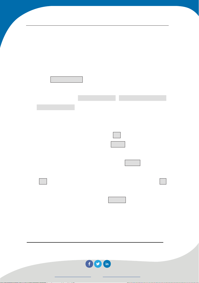
Conventions in this manual
A. Word with gray background and black box is a button on the
interface (e.g., OK button).
B. All buttons on the device panel are shown with【】(e.g.,【OK】
button).
C. Word with white background and black box represent software
menu command in Windows, and “→” is a separator between
different menu levels. For example, File → Open means “Open”
the command under the “File” menu.
D. Words with grey background and without box represent the name
of options or menus on the screen. Such as Object option in
selection parameter setup.
E. Sign
F. Besides descriptions in the manual, some prompt messages may
show automatically in the use of the software. Please operate
accordingly.
G. Software interfaces and pictures in this instruction manual are
only for reference. There will be changes with software upgrade
and improvement of products. No further notice is provided.
means special attention is needed here.
Novatest S.r.l.
info@novatest.itwww.novatest.it
Page 9

Manual for Multichannel Ultrasonic Pile Integrity Tester
Chapter 1 General
1.1 Brief introduction
ZBL-U5600/U5700 multichannel ultrasound pile integrity tester
is a portable special instrument which uses ultrasonic transmission
method to test the integrity of concrete foundation pile; By adopting
multichannel self-transmitting and receiving circuit, this instrument
may test multiple profiles simultaneously; putting three or four
transducers in pipe may realize full combination test for three or six
profiles, which dramatically improves test efficiency and reduces the
work intensity of on-site tester.
1.2 Main functions and features
1.2.1 Main functions
1) Ultrasonic transmission method for testing the
integrity of foundation pile (called “pile test” for
short)
2) Ultrasonic-rebound combined method for testing
compressive strength of concrete (called “strength
test” for short);
3) Ultrasonic transmission method for testing defect
and cavity in structural member (called “defect test”
for short);
4) Ultrasonic flat-measured method for testing crack
depth of concrete surface (called “crack test” for
Novatest S.r.l.
1
info@novatest.itwww.novatest.it
Page 10

Manual for Multichannel Ultrasonic Pile Integrity Tester
short);
1.2.2 Main Features
1) Multichannel self-transmitting and receiving full
combination ultrasonic test for foundation pile may
automatically and continuously collect and save
information such as depths, acoustic parameters and
waveforms of all test points on multiple profiles. With
steady and undistorted waveform, accurate interpretation of
acoustic parameter and excellent repeatability and
consistency, the on-site test speed may be dramatically
improved;
2) During the test, the test result is available and the graphic
distribution of abnormal points in each profile is shown at
any time. Meanwhile, wave train figure, curve graph and
data list of each profile may be shown;
3) During the test, sampling delay and amplification factor
may be adjusted at any time;
4) Radial transducer may be played back at any time without
any operations for repeating test;
5) With true color highlight LCD, waveform, wave speed and
amplitude of multiple tested profiles may be clearly
observed on site Data, curve, wave train figure and
schematic graph of pile integrity of all test points in all
profiles may be checked at any time, the quality of whole
pile in the test is very clear.
6) It adopts WinCE operation system with press screen and
user-friendly interface, which is simply, easy to learn and
convenient to operate;
7) With high-capacity SD card, there is no need to worry
about the storage space of test data;
Novatest S.r.l.
2
info@novatest.itwww.novatest.it
Page 11

Manual for Multichannel Ultrasonic Pile Integrity Tester
8) Built in high-performance and capacity lithium battery may
satisfy fieldwork for long time.
9) Various USB ports may be used for data transmission or
software update within the instrument or external units
such as mouse or keyboard.
10) Test data of the same project is saved under the folder
created with the title of the project for easy and reliable
management.
1.2.3 Relevant test specification
1) Technical Code for Testing of Building Foundation Piles
(JGJ106)
2) Technical Specification for Pile Testing of Highway
Engineering(JTG/T F81-01)
3) Technical Specification for Testing of Foundation Piles of
Railway Engineering(TB 10218)
4) Guangdong Province Standard – Technical Code for Testing
Building Ground Foundation(DBJ15-60)
5) Technical Specification for Testing Building Foundation
Piles in Shenzhen(SJG09)
1.3 Main Technical Specifications
Table 1.1 Main technical specifications
Item
U5600 U5700
Number of
channels
Number of profiles 3 6
Three channels,
individually
controllable
Novatest S.r.l.
Indicators
Four channels, individually
controllable
3
info@novatest.itwww.novatest.it
Page 12

Manual for Multichannel Ultrasonic Pile Integrity Tester
under test
simultaneously
Testing and reading
precision of
acoustic time
Maximum system
dynamic range
Precision of gain
control
Amplitude
measurement error
Receiving
sensitivity
Sampling interval
Number of
waveform points
Transmitting
voltage
Testing and reading
range of acoustic
time
channel crosstalk ≤1/400
0.025μs∼1638.4μs, optional multiple levels
512、1024、2048、4096, optional multiple levels
65V、250V、500V、1000V, optional multiple levels
Frequency
bandwidth
Power supply mode
Operation time ≥8 hours
Total weight 2.5kg (including built-in lithium ion battery)
Whole volume 270 mm×220 mm×75 mm
Monitor 10.4 inch, highlight, true color LCD
Operating mode Press screen
Communication
interface
AC: 220V±10%,DC: +12V
USB port, Mini port and Bluetooth, etc.
0.025μs
154dB
0.5dB
≤1dB
≤10μV
±1677ms
2∼500kHz
Novatest S.r.l.
4
info@novatest.itwww.novatest.it
Page 13

Manual for Multichannel Ultrasonic Pile Integrity Tester
1.4 Precautions
1. To make better use of the tester, please read this operation
manual carefully before use.
2. Requirements of operating environment:
Ambient temperature: 0℃~40 .℃
Relative humidity: <90%RH.
Don’t expose to direct sunlight for long term.
Corrosion protection: necessary precautions shall be
taken when used in damp, dusty or corrosive gas environment.
3. Requirements of storage environment
Ambient temperature: -20℃~+50 .℃
Relative humidity: <90%RH.
When not in use, please pack the device and store it
under ventilation, cool and dry environment. Don’t expose to
direct sunlight for long term.
If the device won’t be used for a long time, power on
and start up the device at regular intervals to have a check.
4. Avoid water ingress.
5. Anti-magnetism: avoid using the device under intense magnetic
field environment, such as near large electromagnet and
transformer.
6. Vibration-proof: prevent strenuous vibration and shock during
operation and transportation.
1.5 Device Maintenance and Preservation
1. Power supply: the instrument adopts special built-in
rechargeable lithium battery as power supply, please pay attention to
the battery indicator during the operation. Use external power supply
(AC power supply or external rechargeable battery) as soon as
Novatest S.r.l.
5
info@novatest.itwww.novatest.it
Page 14

Manual for Multichannel Ultrasonic Pile Integrity Tester
possible if the battery is low, otherwise sudden power failure may
cause loss of test data or even system damage; make sure the external
power supply is AC220±10% V when supplied by AC power,
otherwise AC-DC power supply module or even instrument may be
damaged. The device must not be supplied by other batteries and
power sources.
NOTE: After the battery of the device is exhausted,
system data and time may be lost and require resetting after
startup.
2. Charging
When the matching AC-DC power supply module is charging for
internal battery, user only needs to insert the power plug into socket of
AC220±10% V and insert the DC output to the power plug of
instrument. When charging indicator on the instrument side panel is
red, it means the built-in battery of the instrument is charging; when
indictor turns into green, it means the battery is fully charged. (The
description above is the switch of indicator colors when in shutdown
mode and non-operating status)
NOTE: To ensure full charging, please keep continuous
charging for about 8 hours and at the meantime don’t charge the
device under the environment of above 60℃.
If the device won’t be used for a long time, the rechargeable
battery would discharge naturally, resulting in decreasing of battery
level. Re-charge the device before use. During the charging, the
instrument and the AC-DC power supply may be heated which is
normal, please keep good ventilation for the instrument, AC-DC
power supply and charger in order to dissipate heat.
NOTE: Don’t charge the device with other power
adapters; otherwise, the device might be damaged.
3. Rechargeable battery: the service life of rechargeable battery is
about 500 times of charging and discharging. When nearing the end of
Novatest S.r.l.
6
info@novatest.itwww.novatest.it
Page 15

Manual for Multichannel Ultrasonic Pile Integrity Tester
service life, if the battery is found to operate abnormally (the battery
cannot be charged at all, cannot be fully charged or runs for a short
time after every full charging), the rechargeable battery might be
damaged or reach to the end of its service life. Please contact us to
replace new battery. Battery short circuit or near high temperature heat
source is prohibited.
4. Sensor: Since strong impact or vibration may result in sensor
performance reduction or damage, sensor dropping from height or
beneath weight shall be avoided.
5. After every use, the device shall be cleaned properly, to
prevent water, mud and etc. from entering into the connector, thus
resulting in performance reduction or damage of the device.
NOTE: Don’t put the device or its accessories into
water or wipe them with wet cloth!
Don’t rinse the device or its accessories with organic
solvents!
Please wipe the host and socket with soft clean and dry cloth!
Please clean socket with clean and soft brush.
6. Storage: when not in use, please pack the device and store it
under ventilation, cool, dry and room temperature environment.。 If
the device won’t be used for a long time, power on and start up the
device at regular intervals to have a check.
1.6 Responsibility
The device is sophisticated detection equipment. Our company is
not responsible when the user commits one of the following acts or
other artificial destruction.
1. Violate the aforementioned operating or storage
Novatest S.r.l.
7
info@novatest.itwww.novatest.it
Page 16

Manual for Multichannel Ultrasonic Pile Integrity Tester
environment requirements.
2. Abnormal operation.
3. Open the enclosure and dismantle any parts and components
without permission.
4. The device is seriously damaged by human or fortuitous
accidents.
Novatest S.r.l.
8
info@novatest.itwww.novatest.it
Page 17

Manual for Multichannel Ultrasonic Pile Integrity Tester
Chapter 2 Instrument Description
2.1 Instrument Composition
U5600/U5700 multiple channel ultrasonic pile integrity tester is
composed of host, radial transducer, counting device (or depth
recorder) and accessories (including power adaptor and U disk, etc.).
2.1.1 Host
Picture of U5700 Multichannel Ultrasonic Pile Integrity Tester
appearance is shown in Figure 2.1.
9
Novatest S.r.l.
info@novatest.itwww.novatest.it
Page 18
Manual for Multichannel Ultrasonic Pile Integrity Tester
a) Tthe obverse side
10
Novatest S.r.l.
info@novatest.itwww.novatest.it
Page 19

Manual for Multichannel Ultrasonic Pile Integrity Tester
b) The reverse side
c) The left side
11
Novatest S.r.l.
info@novatest.itwww.novatest.it
Page 20
Manual for Multichannel Ultrasonic Pile Integrity Tester
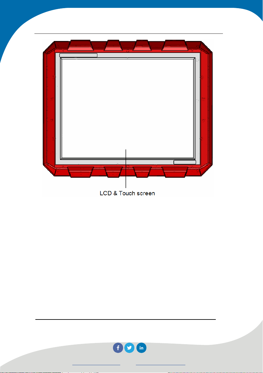
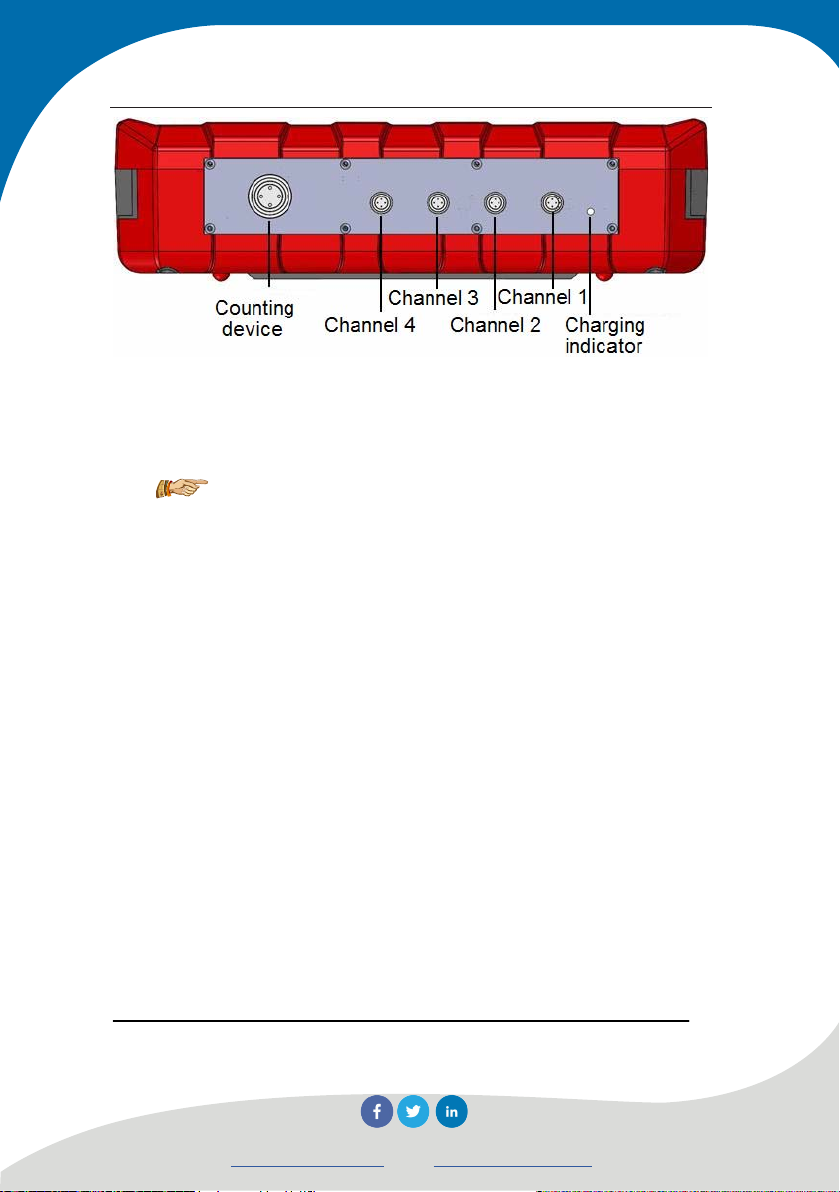
d) Front
Figure 2.1 Picture of host appearance
NOTE: The pictures above are only for reference and
may be different from the actual instruments.
2.1.1.1 LCD and press screen
LCD is mounted on instrument panel and clings to press screen.
It is used to display operation interface and test data. Protective film
on press screen surface may effectively protect press screen, and be
replaced after damage.
2.1.1.2 Power switch
It is used to power on/off instrument, long press the button of
power switch for powering on instrument and long press again for
powering off instrument. During the startup, short press power switch
12
Novatest S.r.l.
info@novatest.itwww.novatest.it
Page 21

Manual for Multichannel Ultrasonic Pile Integrity Tester
to pop up shutdown prompt, select Yes for shutdown, or else select
No.
2.1.1.3 Power socket
Insert input plug of power adaptor supplied with the instrument
into 200-240V AC power output socket to supply power for the
instrument and charge the internal battery as well.
2.1.1.4 Charging indicator
When charging indicator on the instrument side panel is red, it
means the built-in battery of the instrument is charging; when
indictor turns into green, it means the battery is fully charged .
Notes: The description above is the switch of
indicator colors when in shutdown mode and non-operating
status.
2.1.1.5 USB port
Standard USB port is provided for U disk to copy test data of
instrument and save it in computer for further analysis and file by
analysis software in Windows, or to upgrade of internal software of
the instrument.
13
Novatest S.r.l.
info@novatest.itwww.novatest.it
Page 22

Manual for Multichannel Ultrasonic Pile Integrity Tester
2.1.1.6 Mini USB Port
It is provided for connecting with PC and data transmission.
2.1.1.7 Counting device port
Connect the instrument with counting device (depth recorder)
through completely inserting the “projection” of signal wire end into
“groove” of this port and screw to tighten it.
2.1.1.8 Transducer adaptor
It is used for connection with plug of signal wire on transducer.
Adaptors of transducer on instruments in various models are
different (Model U5700 has four adaptors: Channel 1-4, Model
U5600 has only three adaptors: Channel 1-3). Completely insert the
“projection” of signal wire end into “groove” of this port for
connection.
2.1.1.9 Protective cover
USB port and power sockets etc. have protective cover
separately which is not used usually and only opened in operation for
protecting ports above mentioned.
14
Novatest S.r.l.
info@novatest.itwww.novatest.it
Page 23

Manual for Multichannel Ultrasonic Pile Integrity Tester
2.1.1.10 Support
Erect the instrument on horizontal worktop with certain dip
angle through adjusting support angle on the back for convenient
operation.
2.1.1.11 Nameplate
It indicates company name, manufacture date and factory number,
etc.
2.1.2 Transducer
2.1.2.1 Planar Transducer
Figure 2.2 Planar transducer
Composite-structure longitudinal vibration transducer (also
15
Novatest S.r.l.
info@novatest.itwww.novatest.it
Page 24

Manual for Multichannel Ultrasonic Pile Integrity Tester
known as sandwich or trumpet type transducer, commonly known as
“planar transducer” as shown in Figure 2.2) is a kind of simple
radiator utilizing thickness vibration of piezoelectric ceramics. Planar
transducer, with interchangeable radiation and receiving functions, is
used to test concrete strength and internal defect, etc.
Planar transducer is optional part. User needs two planar
transducers and signal wire for testing strength or defect of concrete
structural members.
2.1.2.2 Radial transducer
Radial transducer, also known as tubular transducer, as a kind of
columnar transducer with good symmetric properties, is particularly
suitable for penetration test of cross-hole sound wave. Radius
transducer is the sensor for transmitting and receiving ultrasonic as
shown in Figure 2.3. All special transducers with same and
interchangeable ports for multichannel pile integrity tester may be
used for transmitting and receiving. According to different number of
channels, radial transducers in different numbers may be equipped.
The length of transducer signal wire depends on the length of
foundation pile to be tested. The radial transducer for ultrasonic pile
integrity tester is special transducer which cannot be matched with or
connected to other ultrasonic instrument.
16
Novatest S.r.l.
info@novatest.itwww.novatest.it
Page 25

Manual for Multichannel Ultrasonic Pile Integrity Tester
Figure 2.3 Radial transducer
2.1.3 Counting device
Counting device (depth recorder), used for recording the depth
of transducer in pipe, may wirelessly communicate with host or
connect with hose through signal-enhancement wire. Counter wheel
must be paired with host in advance for wireless way in test; for
wired connection, just connect the countering device with host
through signal wire.
NOTE: The distance between countering device and
host adopting wireless communication shall be kept within 5m.
17
Novatest S.r.l.
info@novatest.itwww.novatest.it
Page 26

Manual for Multichannel Ultrasonic Pile Integrity Tester
Figure 2.4 Picture of counter wheel
Long press button to switch on or switch off counter wheel;
fast flashing of operation indicator after counter wheel has been
powered on refers to waiting for connection with host; after
successful connection with host, the operation indicator turns into
green and depth counting is available. When built-in lithium battery
18
Novatest S.r.l.
info@novatest.itwww.novatest.it
Page 27
Manual for Multichannel Ultrasonic Pile Integrity Tester
in counting device is low, the operation indicator start flash green,
which means charging is required. Charging indicator on panel turns
into red when built-in battery in counting device is charged; charging
indicator turning into green means the battery is full.
NOTE: Please use special charger and connection
line for charging; counting device may operate for over 20
hours after being fully charged.
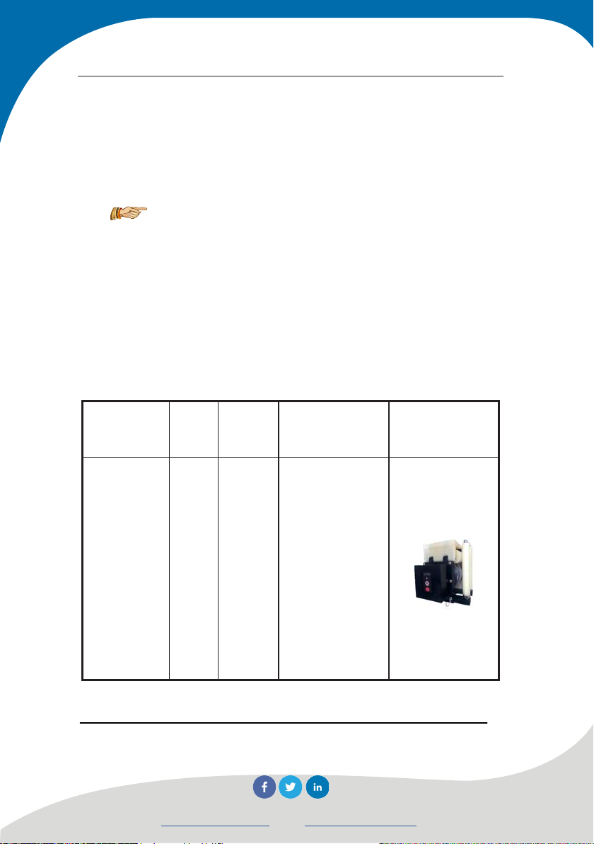
Depth recorder includes counter wheel, guide wheel on pipe
mouth and tripod, etc. as shown in Table 2.1.
Table 2.1 Table of counting device accessories
object
numb
Unit
name
Count wheel Set 1
19
er
Novatest S.r.l.
Description Picture
Connect with
instrument
through Bluetooth
or signal wire,
record position of
transducer and
guide for signal
wire of transducer
info@novatest.itwww.novatest.it
Page 28
Manual for Multichannel Ultrasonic Pile Integrity Tester
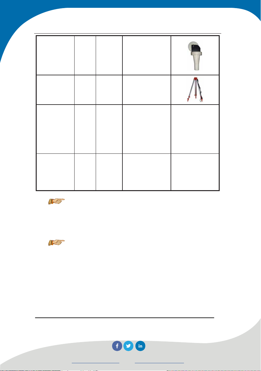
Guide wheel
on pipe
mouth
Tripod
Signal
enhancement
wire
Charger and
connection
wire
3Or 4
Piece
1
Piece
Piece 1
Set 1
Fixed on pipe
mouth to guide for
signal wire
Depth recorder
tripod
Connection wire
for depth
recording wheel
and host
Charge built-in
lithium battery in
counter wheel
(Be omitted)
(Be omitted)
NOTE: Charging connection wire is special
connection wire, one end is standard USB port and another
end is special port.
NOTE: Counting device is supplied power by the
instrument directly when it is connected with instrument by
wire and may operate normally even without power in
built-in lithium battery.
20
Novatest S.r.l.
info@novatest.itwww.novatest.it
Page 29

Manual for Multichannel Ultrasonic Pile Integrity Tester
2.1.4 Accessories
2.1.4.1 Power adaptor
Connect input plug of power adaptor with 200-240V AC power
and its output plug with power plug of host for supplying power to
the instrument and charging the internal battery as well.
2.1.4.2 Other attachments
Refer to the packing list for more retail.
2.2 Test principle
2.2.1 Cross-hole sonic logging for testing pipe integrity
The basic principle of ultrasonic transmission method for testing
pile integrity is: excite high frequency elastic pulse wave through
ultrasonic pulse emission source, use high precision receiving system
to record the fluctuant features of this pulse wave transmitting in
concrete; when concrete has discontinuous or damaged interface
inside, defect surface forms wave impedance interface, therefore,
when wave arrives to such this interface, caused transmission and
reflection of wave obviously decreases the received transmission
21
Novatest S.r.l.
info@novatest.itwww.novatest.it
Page 30

Manual for Multichannel Ultrasonic Pile Integrity Tester
energy; when concrete has serious defects such as looseness,
honeycomb or cavitations, wave scattering and diffraction will be
caused; compactness parameters of concrete in test ranges will be
obtained based on the first arrival time of wave and features of
energy attenuation, frequency change and waveform distortion degree,
etc. The property, size and spatial location of internal defect within
concrete could be obtained through treatment and analysis of tested
and recorded ultrasonic fluctuation features in different profiles and
heights.
Before construction of foundation pile, pipes in certain number
according to the pile diameter shall be pre-buried as the channel for
transducer. Every two pieces of pipe is a group in test, ultrasonic
pulse signal is transmitted from transducer in one pipe and received
by transducer in another one through water coupling (as shown in
Figure 2.5), the instrument will record the acoustic parameter such as
acoustic time and amplitude for determining whether the concrete in
this position between two pieces of pipe is normal or not. Move
transmitting and receiving transducers upward from the bottom of
pile and test the points one by one to understand the concrete
integrity of whole profile. Integrity conditions of each profile or even
the whole pile may be obtained through testing all profiles.
22
Novatest S.r.l.
info@novatest.itwww.novatest.it
Page 31

Manual for Multichannel Ultrasonic Pile Integrity Tester
Figure 2.5 Schematic diagram of cross-hole sonic logging for testing pipe
integrity
2.2.2 Ultrasonic-rebound combined method for
testing concrete strength
This combined method adopts two or more than two test
methods to test several physical quantities and establishes
relationship between them and concrete strength. “Ultrasonic pulse
speed-rebound value” combined method is the method with the most
research and widest application at home and abroad.
By adopting low frequency ultrasonic tester and rebound tester
with standard kinetic energy of 2.207J, ultrasonic-rebound combined
method tests acoustic time and rebound value separately in the same
23
Novatest S.r.l.
info@novatest.itwww.novatest.it
Page 32

Manual for Multichannel Ultrasonic Pile Integrity Tester
2.2.3 Ultrasonic method for testing
test area of structure or structure member, and calculates the concrete
strength in test area through established strength test formula.
Strong relativity exists among the wave speed, rebound value
and strength of concrete; when strength is stronger and wave speed is
faster, the rebound value is higher; after the relationship curve has
been calibrated, test the acoustic time and rebound value separately in
same test area, then calculate the concrete strength by utilizing
established strength test curve (formula 2-1):
cb
(2-1)
ecu
,
RVaf ××=
In which: a - coefficient of constant term; b, c - regression
constant; fcu,e - equivalent value of compressive strength; V –
calibrated ultrasonic speed in test area; R – calibrated average
rebound value in test area.
uncompacted area and cavitation
The speed of ultrasonic transmission is directly related to concrete
compactness, higher speed means compacter concrete and vice versa.
Ultrasonic method detects concrete defect through relative change of
acoustic parameters such as transmission time (or speed), amplitude
and frequency of received wave of pulse wave in concrete with same
technical conditions to judge the defect of concrete. Since cavitations
24
Novatest S.r.l.
info@novatest.itwww.novatest.it
Page 33

Manual for Multichannel Ultrasonic Pile Integrity Tester
or crack may destroy the integrity of concrete, sound wave has to
bypass cavitations or crack and transmit to receiving transducer; the
longer the transmission distance is, the longer the tested acoustic time
is, and acoustic speed decreases correspondingly. Reflection,
scattering and energy attenuation caused by ultrasonic on defect
interface may result in decrease of amplitude; the attenuation degrees
are different when various frequencies in sound wave encountering
defect; high frequency has large attenuation, which makes basic
frequency decreases (frequency shift). Besides, waveform conversion
and addition of sound wave at defect make waveform distortion.
25
Novatest S.r.l.
info@novatest.itwww.novatest.it
Page 34
Manual for Multichannel Ultrasonic Pile Integrity Tester
Chapter 3 Common module description
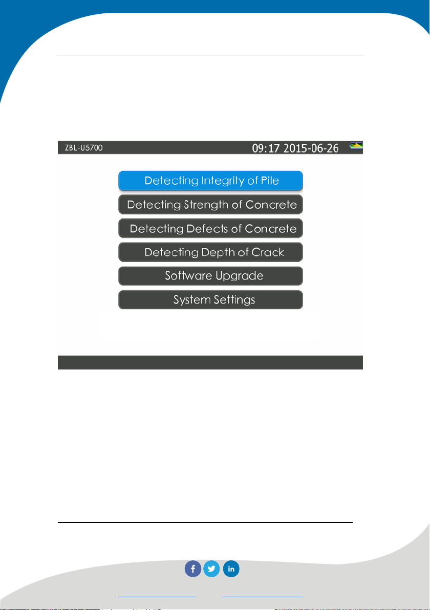
3.1 Startup interface
Figure 3.1 Startup interface
Press power switch and power on instrument, the company logo
will display for a while; after that the instrument will enter into
startup interface as shown in Figure 3.1, displaying system date, time,
remaining capacity and several function buttons (button of red letters
and grey background means not available). Pressing different buttons
to call different software; refer to following chapters for more details.
26
Novatest S.r.l.
info@novatest.itwww.novatest.it
Page 35

Manual for Multichannel Ultrasonic Pile Integrity Tester
Press button to switch to English version and
the button turns into
button to switch to Chinese version and
the button turns into .
3.2 Control introduction
Dialogue box used in the software includes various common
controls, please refer to the Table 3.1 for brief introduction.
Table 3.1 List of controls
Control
name
Button
Edit box
Example Description
Button for certain action
Used for inputting text (number or character)
; press
Pull-down
List including a series of character string,
several options may pop up when pressing
list box
downward arrow
27
Novatest S.r.l.
info@novatest.itwww.novatest.it
Page 36

Manual for Multichannel Ultrasonic Pile Integrity Tester
Single
choice box
Check box
Used when only one option out of multiple
ones may be selected
Used when one or several options out of
multiple ones may be selected: ticking “√”
means being selected, otherwise not
3.3 Soft keyboard
3.3.1 Character input
When need to input character (such as name of project or foundation
pile, etc.), press the edit box behind it, the soft keyboard as shown in
Figure 3.2 will pop up. Title bar will display the name of project and
maximum character number to be input, and edit box will display the
current character.
28
Novatest S.r.l.
info@novatest.itwww.novatest.it
Page 37

Manual for Multichannel Ultrasonic Pile Integrity Tester
a)Input mode for English
b) Input mode for Chinese
Figure 3.2 Character soft keyboards
29
Novatest S.r.l.
info@novatest.itwww.novatest.it
Page 38

Manual for Multichannel Ultrasonic Pile Integrity Tester
Operational approach of press screen is as follows:
1) When press the button of a given character or number, it
will be shown in the edit box above one by one;
2) If need to insert a character in front of a given input
character, press the place in front of the character at first, insert
the cursor in front of it and press the character which needs to be
inserted.
3) Press BS button to delete the character in front of cursor;
during the input of Chinese, delete Pinyin alphabet at first and
then character in edit box. Long press of BS button for quick
deletion. It is equivalent to the Backspace key on physical
keyboard.
4) Press ↑ button to shift into capital mode and press any
character back to lower case. It is equivalent to the Shift key on
physical keyboard; long press ↑ button to lock up capital mode,
it is equivalent to the Caps Lock key on physical keyboard.
5) Press
button to shift in Chinese input mode as shown
in Figure 3.2b, and the button turns into Eng at the same time,
which means Chinese can be input through Pinyin now. After
Pinyin characters have been input, optional Chinese characters
will be shown on the bottom of input box (if there are many
optional Chinese characters, press < and > buttons to display
other Chinese characters), press the position of character to input
30
Novatest S.r.l.
info@novatest.itwww.novatest.it
Page 39

Manual for Multichannel Ultrasonic Pile Integrity Tester
it; when press the En button, it will turn into and recover
to the mode as shown in Figure 3.2a.
6) After have pressed OK button, the input is valid and soft
keyboard is closed; if the input character is illegal or
unreasonable, relevant prompt will be shown on the bottom;
7) After have pressed Cancel button, the input is invalid and
soft keyboard is closed.
3.3.2 Number input
Figure 3.3 Numeric soft keyboards
When need to input number (such as starting elevation and pile
spacing), press the edit box behind it, soft keyboard as shown in
Figure 3.3 will pop up, the title bar displays the name of project to be
31
Novatest S.r.l.
info@novatest.itwww.novatest.it
Page 40

Manual for Multichannel Ultrasonic Pile Integrity Tester
input and its reasonable range, the edit box displays the current
number.
Operational approach of press screen is as follows:
1) When press the button of a given number, it will be shown
in the edit box above one by one;;
2) If need to insert a number in front of a given input number,
press the place in front of the number at first, insert the cursor in
front of it and press the number which needs to be inserted.
3) Press BS button to delete the number in front of cursor,
long press BS button to delete all numbers;
4) After have pressed OK button, the input is valid and soft
keyboard is closed; if the input number is illegal or unreasonable,
relevant prompt will be shown on the bottom;<0}
5) After have pressed Cancel button, the input is invalid and
soft keyboard is closed.
32
Novatest S.r.l.
info@novatest.itwww.novatest.it
Page 41
Manual for Multichannel Ultrasonic Pile Integrity Tester
3.4 Waveform display and operation
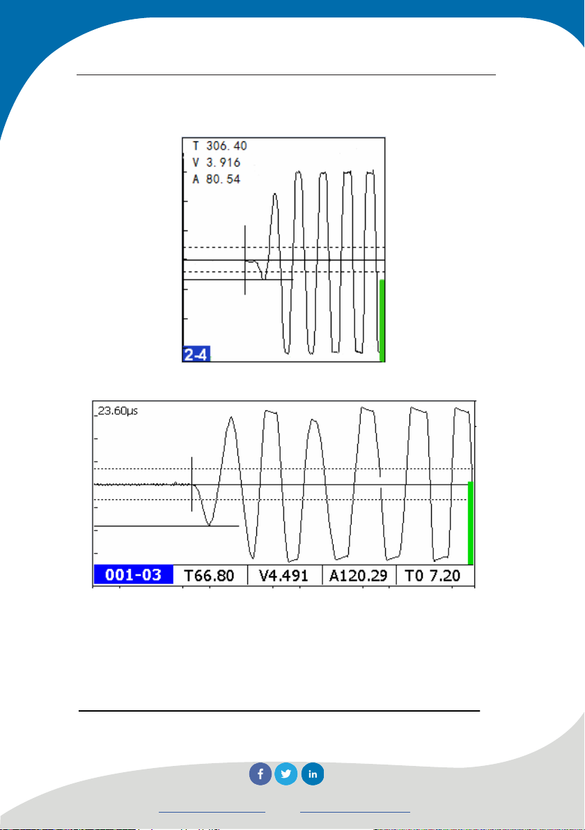
a) Single-channel waveform in pile test
b) Single-channel waveform in strength test, defect test and crack test
Figure 3.4 Schematic graph of waveform
Single-channel waveform range is used to display the waveform
and acoustic parameters, etc. of current testing point as shown in
33
Novatest S.r.l.
info@novatest.itwww.novatest.it
Page 42

Manual for Multichannel Ultrasonic Pile Integrity Tester
Figure 3.4. The top left corner of single-channel waveform range for
pile test displays acoustic parameter of head wave and the lower left
corner displays name of profile, as shown in Figure 3.4a. The bottom
horizontal row of single-channel waveform range for strength test,
defect test and crack test displays acoustic parameter and zero
acoustic time value of head wave, the lower left corner displays series
number of test point, top left corner displays delay time, as shown in
Figure 3.4b.
The vertical progress bar at the right of single-channel
waveform means the gain; when gain is increasing, the progress bar
ascends and when gain is decreasing, the bar descends.
1) Acoustic time value T: Transmission time of ultrasonic
from transmitting transducer to receiving transducer, the
unit is μs, this acoustic time value has deducted the system
zero acoustic time value;
2) Amplitude value A: The amplitude value of received head
wave of ultrasonic, it is used to measure the energy of
ultrasonic and the unit is dB;
3) Acoustic velocity value V:The transmission speed of
ultrasonic in concrete; it is a calculated value and the
calculation method is to divide spacing by T value, the unit
is km/s.
34
Novatest S.r.l.
info@novatest.itwww.novatest.it
Page 43

Manual for Multichannel Ultrasonic Pile Integrity Tester
3.4.1 Terminology
1) Dynamic sampling: It refers to the process of continuously
and repeatedly transmitting, collecting, processing,
interpreting and displaying waveform and acoustic
parameter.
2) Dynamic waveform: It refers to the continuously refreshing
waveform in single- channel waveform range on screen in
dynamic sampling.
3) Static waveform: It refers to the static waveform in
single-channel waveform range on screen when stop
sampling.
4) Head wave (preliminary wave): The first wave crest or
trough of waveform received by instrument.
5) Noise range: Manual-set noise range in dynamic sampling,
it is used to distinguish waveform from noise; any
waveforms with amplitude not exceeding such range is
considered as noise.
6) Threshold value: It is one of the automatic judging criteria
of head wave, only the waveform exceeding threshold
value line will be possibly judged as head wave; the two
dotted lines above and below base line, as shown in Figure
35
Novatest S.r.l.
info@novatest.itwww.novatest.it
Page 44

Manual for Multichannel Ultrasonic Pile Integrity Tester
3.4, are threshold value lines.
7) Base line: The approximate straight line in front of head
wave in the waveform. Longitudinally symmetrical
central line of single- channel waveform.
8) Automatic interpretation line for acoustic time: It is used to
indicate the mark line for ultrasonic system to
automatically test and read acoustic time position of head
wave.
9) Automatic interpretation line for amplitude: It is used to
indicate the mark line for ultrasonic system to
automatically test and read the amplitude position of head
wave.
10) Gain: The magnification to received signal by the system.
11) Number of delay points: The number of transmission
starting points relative to “0” point position in
single-channel waveform range.
36
Novatest S.r.l.
info@novatest.itwww.novatest.it
Page 45

Manual for Multichannel Ultrasonic Pile Integrity Tester
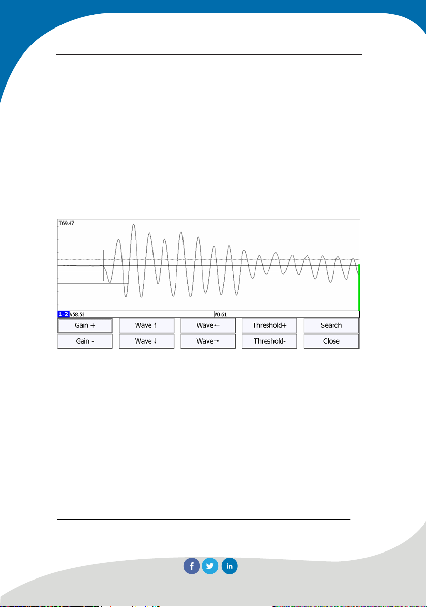
3.4.2 Dynamic waveform operation
3.5 Operation panel for dynamic waveform
In dynamic sampling, press the bottom right of the
single-channel waveform range, operation panel as shown in Figure
3.5 will pop up under the waveform.
1) Adjust gain
Press Gain+ and Gain- button or slide up and down on
waveform range to increase or decrease gain.
2) Move dynamic waveform
Slide the position of central base line of single- channel
waveform forward and backward or press Wave←and Wave→
buttons to move dynamic waveform left or right, and consequently,
decrease or increase number of delay points;
3) Automatic search
37
Novatest S.r.l.
info@novatest.itwww.novatest.it
Page 46

Manual for Multichannel Ultrasonic Pile Integrity Tester
Press Search button for automatic sampling and searching the
head wave of current waveform.
4) Adjustment of base line
Press Wave↑ and Wave↓ buttons to adjust base line position
upward or downward;
5) Adjustment of noise range width
Press Threshold+ and Threshold– buttons to increase or
decrease threshold value for determining head wave;
6)Close operation panel
Press any areas outside of single-channel waveform range to
close operation panel.
3.4.3 Static waveform operation
In the state of static waveform, press a certain waveform in
single-channel waveform range to use this channel as current channel,
one transverse cursor and one vertical cursor will appear in waveform
range, and operation panel as shown in Figure 3.6 will pop up under
current waveform.
38
Novatest S.r.l.
info@novatest.itwww.novatest.it
Page 47

Manual for Multichannel Ultrasonic Pile Integrity Tester
Figure 3.6 Operation panel for static waveform
1) Move cursor left and right
Press Left and Right buttons to move vertical (acoustic time)
cursor and display acoustic time value at cursor position in cursor
parameter area.
2) Move cursor up and down
Press Up and Down buttons to move transverse (amplitude)
cursor and display acoustic time value at cursor position in cursor
parameter area.
3) Move waveform left and right
Press Wave← and Wave→ buttons to move waveform left
and right.
4) Save the manual interpretation result
After have located the transverse (amplitude) and vertical
(acoustic time) cursors, press Save button on operation panel to
save cursor determining result, which means use the acoustic
time and amplitude values at cursor position to replace the
39
Novatest S.r.l.
info@novatest.itwww.novatest.it
Page 48
Manual for Multichannel Ultrasonic Pile Integrity Tester
acoustic time and amplitude values of current test point.
5) Close the operation panel
Press any areas outside of single-channel waveform range
to close operation panel.
3.4.4 Magnify and display single-channel
waveform
Figure 3.7 Magnify and display single- channel waveform
In the state of dynamic sampling, press the position of series
number or profile name at the lower left corner of single-channel
waveform range, the dialogue box as shown in Figure 3.7 will pop up
to magnify and display this waveform, the function of button at
bottom are as same as that described in Section 3.4.2. When press
other profile waveforms, the name of profile at lower left corner will
change to current series number and waveform correspondingly.
40
Novatest S.r.l.
info@novatest.itwww.novatest.it
Page 49

Manual for Multichannel Ultrasonic Pile Integrity Tester
Press Close button to close the dialogue box.
NOTE: Only pile testing software has this function.
3.5 File Management
File management is used to check the tested projects and files
and copy the selected projects or files to U disk; or upload it to server
or delete it.
Figure 3.8 File management interface
The interface of file management is as shown in Figure 3.8, the
left part of interface is project list, right part is list of all files of the
41
Novatest S.r.l.
info@novatest.itwww.novatest.it
Page 50

Manual for Multichannel Ultrasonic Pile Integrity Tester
current project and lower part is function button area. When data list
has a lot of information, scroll bar will appear at side of list box; drag
scroll bar to turn page and display, or slide it up and down is list area
to flip screen.
3.5.1 Operating mode
1)Press a certain project in project list, all files (without
extension) in this project will be listed in the file list. Press the
row where the file is located in the list files to select this file.
2)Press the list header for sorting, different columns has
different sorting method, name column is sorted according to
alphabetical order, time column is sorted according to
chronological order, and file size column is sorted according
to file size. Pressing for several times may switch over the
sorts by ascending order and descending order.
3)Press the first column of list header to tick off all projects or
files.
4)Press the check box in front of a certain project or file in
project or file list to tick off this project or file; press projects
or files which need to be selected to tick off several projects
or files.
42
Novatest S.r.l.
info@novatest.itwww.novatest.it
Page 51

Manual for Multichannel Ultrasonic Pile Integrity Tester
3.5.2 Open file
Select a file in file list area and press Open button to open the
selected file and return to main interface, displaying the waveform
and curve stored in this file. When no file is selected, Open button is
invalid.
3.5.3 Project and file copy
Tick off one or more projects and press Copy button to copy all
files in selected project to U disk; Tick off one or more files and press
Copy button to copy all selected files to U disk. When no project or
file is selected, Copy button is invalid.
Folder with name of “U5Pile” will be created in U disk when
copy project or file; create a subfolder with the name of the project
and then copy all files or selected files of this project to the subfolder.
Check whether U disk exists before copy file; if not, it will
prompt user to insert U disk at first.
3.5.4 Project and file deletion
Tick off one or more projects and press Delete button to delete
selected project and all files in it; Tick off one or more files and press
Delete button to delete the selected files. When no project or file is
selected, Delete button is invalid.
43
Novatest S.r.l.
info@novatest.itwww.novatest.it
Page 52

Manual for Multichannel Ultrasonic Pile Integrity Tester
It will be inquired that “whether delete selected project or file?”,
press Yes to delete it, press No for not.
NOTE: Deleted data cannot be recovered! Make sure
all data to be deleted has been kept a backup in computer
before deletion. When all data files of one project have been
deleted, the project folder will be deleted automatically.
3.5.5 Project and file upload
Tick off a project in project list and press Upload button to
upload all files in this project to test management system.
Tick off one or more files in file list and press Upload button to
upload the selected files to test management system.
When no project or file is selected, Upload button is invalid.
NOTE: Developed by Beijing ZBL Science and
Technology Co., Ltd, this test management system is used to
manage the whole process of nondestructive test; only users
who have bought this system may upload test data. Please
refer to the Operation Manual for details.
3.5.6 Exit
Press Quit button to exit from file management and return to main
interface.
44
Novatest S.r.l.
info@novatest.itwww.novatest.it
Page 53

Manual for Multichannel Ultrasonic Pile Integrity Tester
3.6 Zero set
Zero acoustic time refers to the acoustic delay between
ultrasonic instrument and transmitting and receiving transducers; zero
acoustic time must be eliminated in testing acoustic time value. Zero
set obtains zero acoustic time through test. This operation is required
when operate ultrasonic instrument and replace transducer or signal
wire in the first time.
3.6.1 Manual zero set
After have read acoustic time on waveform, find out the option
of Zero acoustic time in parameter interface, and input the acoustic
time into it manually.
3.6.2 Acoustic zero set
1) Press the Zero button in parameter interface, input
standard acoustic time in pop-up dialogue box as shown in
Figure 3.9(If use standard rod for zeroset, input the standard
acoustic time value of standard rod; if use coupling
transducer for zeroset, input 0).
2) Couple transducer according to the prompt message, press
Zero button to close this dialogue box, start sample
automatically, display waveform in waveform range and
45
Novatest S.r.l.
info@novatest.itwww.novatest.it
Page 54

Manual for Multichannel Ultrasonic Pile Integrity Tester
search head wave automatically.
Figure 3.9 Dialogue box for zeroset
3) Adjust waveform in main interface, press Stop button to
stop sampling after have found head wave, and prompt
message of new tested zero acoustic time (As shown in
Figure 3.10) will pop up automatically, press Yes button to
complete zeroset; the current acoustic value is set as zero
acoustic time, which will be written into parameter file.
Press No to cancel this zeroset result.
46
Novatest S.r.l.
info@novatest.itwww.novatest.it
Page 55

Manual for Multichannel Ultrasonic Pile Integrity Tester
Figure 3.10 Prompt of new tested acoustic time
NOTE: This function is only applicable to software
for strength test, defect test and crack test; automatic zeroset is
only available when just enter into test interface and no data
has been collected.
3.7 Retest
a) Start retesting b) Finish retest
Figure 3.11 Dialogue box of retest
If need to retest the tested point, select the point which needs
47
Novatest S.r.l.
info@novatest.itwww.novatest.it
Page 56

Manual for Multichannel Ultrasonic Pile Integrity Tester
to be retested in data list area, press Retest button to pop up prompt
box as shown in Figure 3.11a. After have coupled transducer with
the first point to be tested according to the prompt message, press
OK button to enter into retest mode, retest the points one by one
and save results until cancel retest mode or all points have been
retested. Retest button flashing in retesting samples means retest is
in progress.
If need to cancel retest, repress Retest button when stop
sampling in waveform, which means static waveform, prompt box
as shown in Figure 3.11b will pop up, press OK button to cancel
retest mode.
NOTE: This function is only applicable to software
for strength test, default test and crack test;
3.8 Battery level
Battery level is displayed by 5 boxes to divide battery level into
5 sections reasonably.
1) When battery level remains only 1 box, it will prompt as
“Low battery level, please save data and charge in time”, as
shown in Figure 3.12.
48
Novatest S.r.l.
info@novatest.itwww.novatest.it
Page 57

Manual for Multichannel Ultrasonic Pile Integrity Tester
Figure 3.12 Prompt messages for low batter level
2) When battery level remains 0 box, the instrument will shut
down after has saved data. The instrument will shut down
directly if no data needs to be saved.
3.9 Shutdown
There are three conditions in shutdown:
1) Short press power switch, if there is no data needs to be
saved, the prompt of “Shut down or not?” will appear, select
Yes to shut down, Select No for not.
2) Short press power switch, if there are some data to be saved,
the prompt of “Shut down or not?” will appear, select Yes to
save the data and shut down, Select No for not.
3) Long press power switch for hardware shutdown and
stopping software operation, which is similar to long press
power-off button on computer.
49
Novatest S.r.l.
info@novatest.itwww.novatest.it
Page 58
Manual for Multichannel Ultrasonic Pile Integrity Tester
3.10 System Setup
The system setup function is used to set instrument information
and public parameter.
Press System Setting button in startup interface to pop up
dialogue box as shown in Figure 3.9. This dialogue box includes
three property pages of General parameter, Instrument information
and Internet parameter, as shown in Figure 3.13, 3.15 and 3.16
separately. The default of each parameter is the value which has been
set last time.
After have set all parameters, press OK button to validate all
sets and return to startup interface, press Cancel button to invalidate
all sets and return to startup interface.
In the interface of system setup, press Default button, the
dialogue box of “whether restore factory setting or not?” will appear,
press Yes button to restore all parameters to factory setting or No
button for not.
In system setup interface, press Versions button to pop up
dialogue box of version information for checking software, hardware,
core or firmware, etc.
50
Novatest S.r.l.
info@novatest.itwww.novatest.it
Page 59

Manual for Multichannel Ultrasonic Pile Integrity Tester
3.10.1 General parameter
Press General label to switch to the property page as shown in
Figure 3.13 for setting System date, System time and Screen
brightness, etc.
Figure 3.13 General parameter
1. System Date
Display system date: Press the pull-down button behind it to pop
up dialogue box as shown in Figure 3.14 to display current date. After
the date has been changed, the setting will become valid immediately,
close the dialogue box, the current system date is changed.
51
Novatest S.r.l.
info@novatest.itwww.novatest.it
Page 60

Manual for Multichannel Ultrasonic Pile Integrity Tester
Figure3.14 System date setup
2. System time
Display system time: Adjust time to select hour, minute or
second and press the spin button behind it. The adjusted time will
become valid immediately and the current system time is changed.
3. Screen brightness
The brightness of LCD may be adjusted within range of 10-100,
the default is 100; press + and - buttons to increase and
decrease brightness; every press changes 10.
52
Novatest S.r.l.
info@novatest.itwww.novatest.it
Page 61

Manual for Multichannel Ultrasonic Pile Integrity Tester
3.10.2 Instrument information
(a)Instrument information
(b)Edit tester
Figure 3.15 Instrument information
53
Novatest S.r.l.
info@novatest.itwww.novatest.it
Page 62

Manual for Multichannel Ultrasonic Pile Integrity Tester
Press Instrument label to switch to the property page as shown
in Figure 3.15 for setting test information and checking instrument ID
number and certificate number, etc.
1. Information setup of test organization and tester
Test organization may be changed: press the edit box behind it
and input the name of test organization through pop-up soft keyboard
for inputting character.
Change of tester and work license number: once the tester is
selected, his/her work license number will display automatically.
Work license number may be changed only after password
verification is successful.
Press Modify Operators button to pop up dialogue box as shown
in Figure 3.15(b), user may delete an add tester and his/her work
license number. After have input tester name and work license
number into the edit box at the top of dialogue box, press Add button
to put it into list; after have selected tester and press Delete button to
delete this tester from the list; press Exit button to exit from tester
edit box.
2. Instrument information setup
Instrument information includes instrument model, ID number
and calibration certificate number, etc. Instrument model cannot be
changed by user and ID number is set in factory. Calibration date
54
Novatest S.r.l.
info@novatest.itwww.novatest.it
Page 63

Manual for Multichannel Ultrasonic Pile Integrity Tester
refers to the latest calibration date; calibration period refers to the
interval between each calibration, usually it is one year. Based on
calibration date and period, the system will remind user to calibrate
instrument at every startup within one month before every expiry date
of calibration.
3. Password verification
Since instrument information can only be changed by the person
with administration authority, all test information is not editable
(except for tester); dialogue box requiring input password will pop up
when press a certain edit box, all test information can be changed
only after password verification is successful.
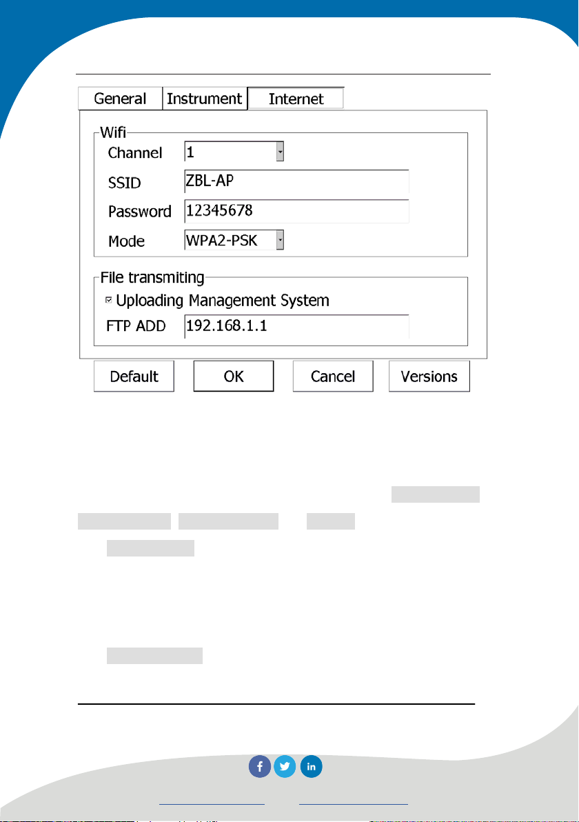
3.10.3 Internet Parameter
Press Internet label to switch to the property page as shown in
Figure 3.16 for setting WIFI parameter and file transmission.
Internet parameters can be changed only by the person with
administration authority, dialogue box requiring input password will
pop up when press a certain edit box, all parameters can be changed
only after password verification is successful.
55
Novatest S.r.l.
info@novatest.itwww.novatest.it
Page 64
Manual for Multichannel Ultrasonic Pile Integrity Tester
Figure 3.16 Internet parameter
1. WIFI Parameter setup
WIFI parameter is used to set relevant parameters when
instrument is connected through WIFI, it includes Network name,
Login password, Encryption mode and Channel.
Network name is the name of WIFI LAN generated by current
instrument, user may find out this WIFI LAN in other terminal units
with WIFI function, the default is “ZBL-(last 6 digits of the
instrument wireless MAC address)”.
Login password is the password required to input when other
terminal units need to log in the WIFI LAN of current instrument, the
56
Novatest S.r.l.
info@novatest.itwww.novatest.it
Page 65

Manual for Multichannel Ultrasonic Pile Integrity Tester
default is “zbl12345678”.
Encryption mode is the way of encryption for login password,
the options include 4 types such as Open, WEP, WPA-PSK and
WPA2-PSK, the default is WPA2-PSK. In consideration of safety, it
is suggested to use WPA2-PSK.
Channel has 12 options from 1 to 12. It is used to set frequency
range for WIFI signal transmission; user may try to change this if
WIFI signal transmission is weak, the default is 1.
2. File transmission setup
Uploading Management System is used to control instrument to
automatically upload new collected data to remote management
system. This function is valid only when used with the matching
management system from our company.
In order to make sure that test data could be transmitted to
correct server through Internet, must input correct FTP address (such
as 202.106.63.52) and port number.
NOTE: In general, FTP and WIFI setting is only
required in the first operation, if there is no change after that,
setup is not necessary anymore.
3.11 Software update
The main function of this module is to automatically update all
57
Novatest S.r.l.
info@novatest.itwww.novatest.it
Page 66

Manual for Multichannel Ultrasonic Pile Integrity Tester
software (listed in startup interface, such as startup interface and
update program) in instrument and relevant files.
After software in instrument has been updated, user may update
it by himself. Before update, user must obtain update program from
our company’s website or through other ways; the update program is
self-extracting program. The update process is simple and as follows:
1) Extract the files in update package to a certain folder in
computer;
2) Insert U disk into USB port in computer, copy the extracted
update files to root directory in U disk, take out U disk after
copy is completed;
3) Insert U disk into USB port of the instrument;
4) Power on instrument, press Software Update button in startup
interface to close current software and Start update program;
press Update button (to copy the update files in U disk to
corresponding folder in the instrument); the prompt of “Software
update is successful” will appear after update is completed;
NOTE: If there is no software needs to be updated in
U disk or U disk cannot be found, the prompt of “Update
program could not be detected, please insert U disk with
update program” will appear; if the update failed due to
storage space in the instrument is not enough, the prompt
of “”File copy failed, please check remaining storage space
58
Novatest S.r.l.
info@novatest.itwww.novatest.it
Page 67

Manual for Multichannel Ultrasonic Pile Integrity Tester
of the instrument!” will appear.
5) Press Close button to exit from update program.
59
Novatest S.r.l.
info@novatest.itwww.novatest.it
Page 68

Manual for Multichannel Ultrasonic Pile Integrity Tester
Chapter 4 Cross-hole sonic logging
software for testing pile integrity
Press Detecting Integrity of Pile button in startup interface to
enter into main interface of pile test software as shown in Figure 4.1,
it is applicable to integrity test of concrete cast-in-place pile with
built-in pipe.
3.1 Main interface
The main interface of the pile test software is composed of three
parts as follow: function button area, single-channel waveform
area and data graphic area. There are two kinds of optional
display modes for main interface to select in View: 1*6 or 2*3. 1*6
means that single-channel waveform with 6 profiles displays in the
same row (as shown in Figure 4.1a), 2*3 means that single-channel
waveform with 6 profiles displays in two rows (as shown in Figure
4.1b).
60
Novatest S.r.l.
info@novatest.itwww.novatest.it
Page 69

Manual for Multichannel Ultrasonic Pile Integrity Tester
a) 1*6 Layout
61
Novatest S.r.l.
info@novatest.itwww.novatest.it
Page 70

Manual for Multichannel Ultrasonic Pile Integrity Tester
b) 2*3 Layout
Figure 4.1 Main interface of pile integrity test
NOTE: the single-channel waveform area and bar
graph area are divided into six small areas at most according to
different number of channels in use.
1)Function button area: it is composed of several function
buttons such as File, Parameter and Sample, etc. as shown in Figure
4.1; each button may implement one common function; when button
color is grey, it means this function is invalid in such condition.
2 )Singe-channel waveform area: It is used to display
waveform and acoustic parameter of current test point in each profile;
62
Novatest S.r.l.
info@novatest.itwww.novatest.it
Page 71

Manual for Multichannel Ultrasonic Pile Integrity Tester
please refer to Section 3.4 for details.
3)Data graphic area: It is used to display bar graph, curve
graph and wave train graph, etc. And different graphs may be
switched through View button. Refer to Section 4.4 in this chapter
for details.
4)Title bar: It is used to display project name, foundation pile
name and current depth, etc. The three icons at right side separately
indicate battery level of lifting device, Bluetooth connection status
and battery level of host. When Bluetooth icon is flashing, it means
that host failed to connect with lifting device.
3.2 Parameter setup
Press Parameter button in main interface of pile test to pop up
dialogue box as shown in Figure 4.2. Press Advanced to pop up
property page of General parameter and Other parameters. Default of
each parameter is the value set at last time.
After have set all parameters, press OK button to validate all
settings and return to main interface; press Cancel button to
invalidate all settings and return to main interface.
63
Novatest S.r.l.
info@novatest.itwww.novatest.it
Page 72
Manual for Multichannel Ultrasonic Pile Integrity Tester
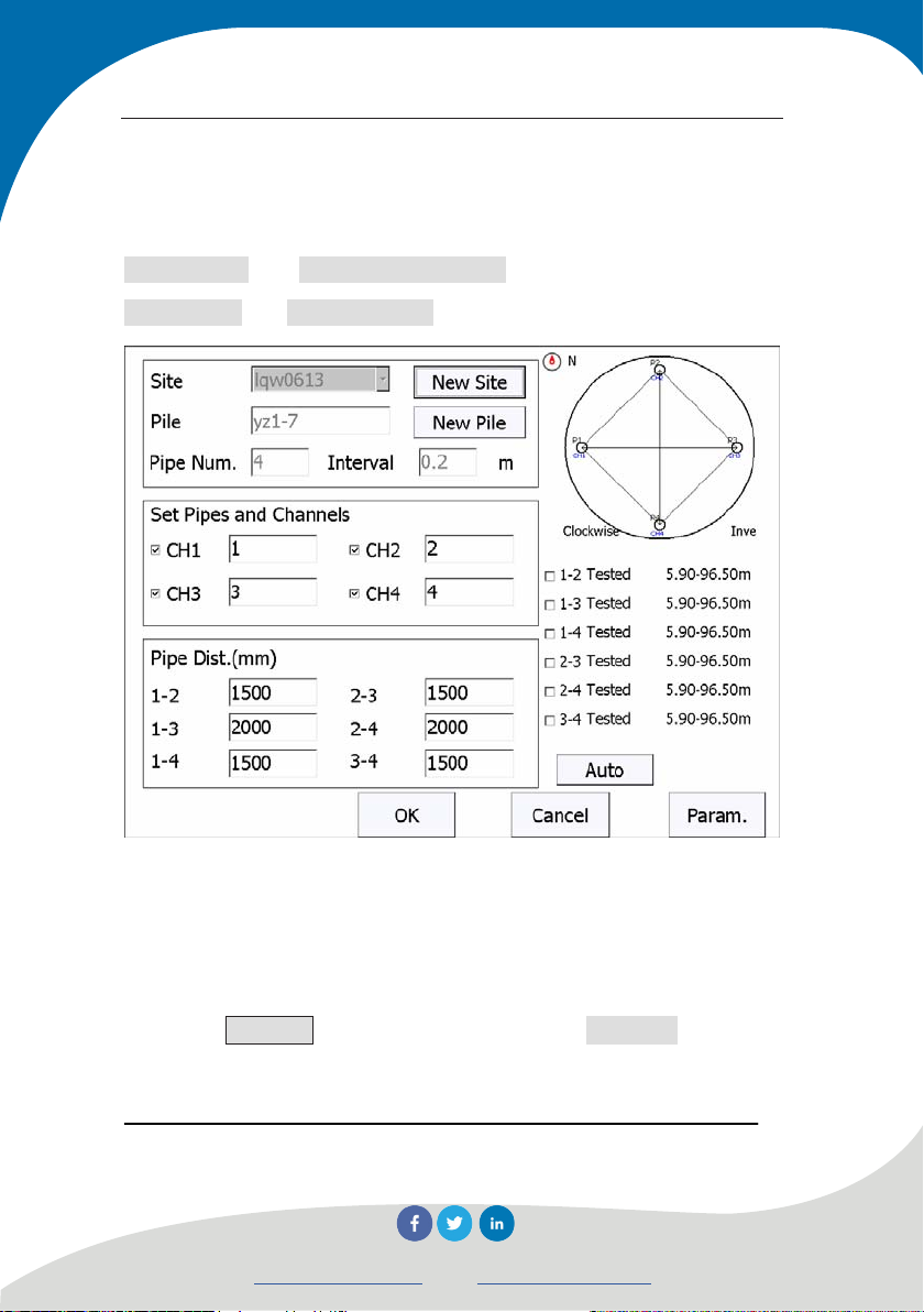
3.2.1 Basic parameter setup
Basic parameter setup interface may be used to create new
Project name and Foundation pile name and set parameters such as
Pipe spacing and Number of pipe, etc.
Figure 4.2 Parameter setup
1. Create new project or select existing project
1) Create new project
Press New Site button behind the list box of Site name to pop up
soft keyboard for inputting character, input project name to create a
subfolder with such name, all data files of tested piles will be saved
64
Novatest S.r.l.
info@novatest.itwww.novatest.it
Page 73

Manual for Multichannel Ultrasonic Pile Integrity Tester
in this folder. When create a folder, if a folder with same project
name has existed, prompt of “This project has existed already, cover
it or not?” will pop up; select Yes button to cover it, if select No,
input box for project name will pop up and require inputting new
project name.
2) Select tested project
Press T button behind pull-down list box of Site to list all tested
projects, select one to save its pile data files in this project.
2. New pile
If need to test a new pile, press New Pile behind Foundation pile
name and input the name of new pile in the pop-up soft keyboard.
When read the file of tested pile or test a certain pile, the name of this
pile will display at here and it cannot be changed.
3. Number of pipes
Press edit box behind the Number of pipes to pop up
single-choice box of number of pipes. The optional value is 2, 3 and 4.
This value is set according to the number of built-in pipes in piles to
be tested. When selected pipe, corresponding schematic graph of pipe
will display on the top right corner of dialogue box for parameter
setting based on the setting of pipe. Meanwhile, the spacing and
profile status of pipe will change accordingly based on the setting of
pipe.
65
Novatest S.r.l.
info@novatest.itwww.novatest.it
Page 74

Manual for Multichannel Ultrasonic Pile Integrity Tester
4. Test point interval
Test point interval refers to the displacement distance of sensor
between two test points. Press the edit box behind it to pop up
dialogue box (as shown in Figure 4.3) to list optional test point
spacing in m. The optional test point spacing includes 0.02, 0.05,
0.10, 0.15, 0.20 and 0.25m, press corresponding value, system will
return to the parameter interface automatically and save the setting.
Press Cancel button to return to parameter setup interface without
changing test point spacing.
Figure 4.3 Test point spacing
5. Pipe and channel setup
Pipe corresponding to the channel is set. U5600 has three
channels and U5700 has four. Every channel may be closed freely;
press check box in front of channel name to open or close channel.
Pipe corresponding to channel behind channel name may be freely
66
Novatest S.r.l.
info@novatest.itwww.novatest.it
Page 75

Manual for Multichannel Ultrasonic Pile Integrity Tester
adjusted according to the position of transducer linked with this
channel in foundation pile.
Example 1: The number of pipes set in U5600 is 3, Channel 1
corresponds to pipe 1, Channel 2 corresponds to pipe 2 and Channel
3 corresponds to pipe 3. In test, Channel 1 and 2 test Profile 1-2,
Channel 1 and 3 test Profile 1-3 and Channel 2 and 3 test Profile 2-3.
Example 2: The number of pipes set in U5700 is 4, Channel 1
corresponds to pipe 1, Channel 2 corresponds to pipe 2, Channel 3
corresponds to pipe 3 and Channel 4 corresponds to pipe 4. In test,
Channel 1 and 2 test Profile 1-2, Channel 1 and 3 test Profile 1-3,
Channel 1 and 4 test Profile 1-4, Channel 2 and 3 test Profile 2-3 and
Channel 3 and 4 test Profile 3-4.
6. Pipe distance
It refers to the clear spacing of sounding pipe outer wall in mm.
System will generate corresponding pipe spacing options
automatically according to the number of pipe. Press edit box behind
corresponding profile name to set pipe spacing in pop-up numerical
soft keyboard.
NOTE: Since pipe spacing may affect data
calculation, please set it correctly.
7. Profile list
It displays profile list of current pile and indicates that whether
each profile has been tested and tested elevation range. System
67
Novatest S.r.l.
info@novatest.itwww.novatest.it
Page 76

Manual for Multichannel Ultrasonic Pile Integrity Tester
selects untested profile as default; tick off or cancel check box in
front of profile name for manual change.
3.2.2 Advanced parameter
Press Advanced button in parameter setup interface to pop up
dialogue box as shown in Figure 4.4. This dialogue box includes two
property pages of General parameter and Other parameters. Default
of each parameter is the value set at last time.
After have set all parameters, press OK button to save
parameters have been set, press Cancel button for not.
Press Reset button in advanced parameter setup interface to pop
up dialogue box inquiring “Whether restore parameter to factory
setting?”; press Yes button to restore all parameters to factory setting
and No for not.
NOTE: If tested data exist, Reset button is invalid.
3.2.2.1 General parameter
Press General label to switch to its property page for setting
parameters such as System delay, Technical specification and
Acoustic speed limit, etc.
68
Novatest S.r.l.
info@novatest.itwww.novatest.it
Page 77

Manual for Multichannel Ultrasonic Pile Integrity Tester
Figure 4.4 General parameter
1. Instrument system delay
System delay input into the instrument. After have input a value
in “Pipe 1-2”, if the option “All profiles of the same” is selected,
values in other pipes are as same as this value. If not selected, value
of each pipe may be changed separately.
2. Selection of technical specification
After have selected corresponding test procedure, data will be
real-time analyzed and processed according to the procedure in test.
3. Acoustic speed limit
Whether limit the range of acoustic speed when search head
69
Novatest S.r.l.
info@novatest.itwww.novatest.it
Page 78

Manual for Multichannel Ultrasonic Pile Integrity Tester
wave, which means search between maximum and minimum acoustic
speed. If selected, search will be limited within acoustic speed range,
if not, the range will not be limited.
4. Stops sampling after transducer coming to pile head
After have selected this option, it will prompt to finish test and
save data when pile length is in zero point in sampling. If not, test
will continue even pile length is over zero point.
5. Acoustic time corrected value of pipe and coupling water
layer
Figure 4.5 Acoustic time corrected value of pipe and coupling water layer
Press Calculate button to enter into interface as shown (in
70
Novatest S.r.l.
info@novatest.itwww.novatest.it
Page 79

Manual for Multichannel Ultrasonic Pile Integrity Tester
Figure 4.5) for setting values of inner diameter and outer diameter of
pipe, outer diameter of transducer, acoustic speed of pipe and
underwater acoustic speed; system will automatically calculate the
corrected value of acoustic time after these values have been input.
In crosshole sonic logging for testing pipe integrity, besides
deduction of Instrument system delay, the transmission acoustic time
of sound wave in pipe wall and water must be deducted as well,
which means the acoustic time corrected value of pipe and coupling
water layer. It shall be calculated as follows :
’
in which, t
—— Acoustic time corrected value (μs);
D —— Outer diameter of pipe (mm);
d —— Inner diameter of pipe(mm);
’
d
—— Outer diameter of transducer(mm);
v
—— Acoustic speed value of pipe wall material(km/s);
t
v
—— Acoustic speed value of water(km/s).
w
6. Wave train graph parameter
Alignment delay: If selected, acoustic time displaying starting
points of all waveforms are the same;
Gain normalization: normalize the gains of waveforms in all
channels to enable amplitudes of all waveforms have comparability.
Channel spacing: spacing between every two waveforms in
71
Novatest S.r.l.
info@novatest.itwww.novatest.it
Page 80

Manual for Multichannel Ultrasonic Pile Integrity Tester
wave train graph, values of 2-50 may be set, the default is 10.
Magnification: Display magnification of waveform in wave
train graph, values of 0.1-1 may be set, the default is 0.2.
7. Acoustic parameter
Acoustic time: if selected, it will display on the top left corner in
single-channel waveform area; otherwise it will not display.
3.2.2.2 Other parameters
Figure 4.6 Other parameters
Press Other Param. label to switch to its property page (as
shown in Figure 4.6), user may set Sampling interval, Number of
waveform points and Transmit voltage; press OK button to save
72
Novatest S.r.l.
info@novatest.itwww.novatest.it
Page 81

Manual for Multichannel Ultrasonic Pile Integrity Tester
parameters which have been set, press Cancel for not. Other
parameters need to be set for only once and it is not required to set
every time. Default of each parameter is the value set at last time.
1. Sampling interval
Select Sampling interval from 17 options including 0.025, 0.05,
0.1, 0.2, 0.4, 0.8, 1.6, 3.2, 6.4, 12.8, 25.6, 51.2, 102.4, 204.8, 409.6,
819.2 and 1638.4. The default is 0.8μs, which is applicable to most
test conditions.
2. Number of waveform points
Number of sample points of collected single-channel waveform
every time: there are 4 options (512, 1024, 2048 and 4096). The
default is 1024. (Suggestion: Do not input large value without special
requirement, otherwise it will negatively affect the speed in dynamic
collection)
3. Transmit voltage
Select excitation voltage value when ultrasonic stimulated
emission transducer generates ultrasonic pulse, there are several
options including 65, 250, 500 and 1000. The default is 500V,
which is applicable to most test conditions. If other test conditions
remain unchanged, the higher transmit voltage is, the stronger
received signal is.
4. Test direction
It may select test upward or downward. The default is upward.
73
Novatest S.r.l.
info@novatest.itwww.novatest.it
Page 82

Manual for Multichannel Ultrasonic Pile Integrity Tester
When test upward, place the transducer in pipe to the pile bottom and
test when lift it upward; when test downward, place transducer on the
top of pile and test when place it downward.
5. Test Mode
Three models including manual, automatic (wireless) and
automatic (wire) are optional. If depth recorder is not equipped, user
must select manual mode and save every test point manually; if depth
recorder is equipped, user may select automatic (wire) or automatic
(wireless), and every test point will be saved automatically. If
wireless communication is adopted between depth recorder and host,
user shall select automatic (wireless); If wire communication is
adopted between depth recorder and host, user shall select automatic
(wire); the default is automatic (wireless).
6. Lifting precision
1)Recalibration
When user thinks the lift position displayed in pile test system is
incorrect and calibration of system lifting precision is required. The
operation method is as follow:
a) Press Recalibrate button in Lifting precision to pop up
dialogue box (as shown in Figure 4.7),place transducer at a
certain place of pipe according to the prompt, read the
depth value on signal wire of transducer at pipe mouth,
press Current depth of transducer edit box, input current
74
Novatest S.r.l.
info@novatest.itwww.novatest.it
Page 83

Manual for Multichannel Ultrasonic Pile Integrity Tester
depth value of transducer into pop-up numerical keyboard
and then press Calibrate;
Figure 4.7 Recalibrate of lifting precision
b) Place the signal wire of transducer into wire duct of counter
wheel and start to lift, the system displays the current
position of counter wheel at this moment;
c) After have lifted 10-30m, stop lifting , read the depth value
on signal wire of transducer at pipe mouth again and input
it into the box of Depth of transducer after lifting, press
OK button to finish calibration of lifting precision; press
Cancel to invalidate the calibration;
75
Novatest S.r.l.
info@novatest.itwww.novatest.it
Page 84

Manual for Multichannel Ultrasonic Pile Integrity Tester
d) If the lifting precision still cannot meet requirement, repeat
steps above to recalibrate it.
2)Precision recovery
Press Reset, system will inquire “whether recover lifting
precision?”, select Yes to recover lifting precision value to factory
setting, select No for not.
7. Counter wheel connection
Press Connect button to enter into interface (as shown in
Figure 4.8).
Figure 4.8 Counter wheel connection
1)List of paired devices: Counting devices which have been
76
Novatest S.r.l.
info@novatest.itwww.novatest.it
Page 85

Manual for Multichannel Ultrasonic Pile Integrity Tester
paired with host will be listed at here, it displays as blank if there is
not paired counting device.
NOTE: For paired Bluetooth lifting device, it will be
connected automatically when power on host and pressing
again for pairing is not required. (Host will connect with counting
device which has been used recently as default.)
2)List of available devices: It displays all counting devices
which can be searched currently. If need to pair a certain counting
device, just press this device in the list. Tick will display behind the
name of paired counting device and the indicator of counting device
will change as well.
3)Search: Press Search button to research unoccupied counting
device nearby.
3.3 Data collection
3.3.1 Start sampling
After have set parameters, press OK button to return to main
interface. Place all transducers at proper position and press Sample
button to automatically Start continuous sampling.
After have adjusted the waveform of first test point in all
profiles, press Save and dialogue box of “Test pile length setup” (as
77
Novatest S.r.l.
info@novatest.itwww.novatest.it
Page 86

Manual for Multichannel Ultrasonic Pile Integrity Tester
shown in Figure 4.9) will pop up to prompt user to input the position
of first test point (height value). This value could be obtained through
depth mark on signal wire of transducer.
Figure 4.9 Test pile length setup
1. Starting point of test
It is the depth (height) value of first test point; after have placed
the transducer on pile bottom, read the marked depth value of signal
wire at pipe mouth.
78
Novatest S.r.l.
info@novatest.itwww.novatest.it
Page 87

Manual for Multichannel Ultrasonic Pile Integrity Tester
2. Pipe blockage setup
If pipe is blocked (which means transducer can not be placed on
pile bottom), tick off check box of Setting blocked position as
shown in Figure 4.9 to set blockage status for each pipe. If pipe is not
blocked, depth value of each pipe shall be the same; otherwise the
depth value of blocked pipe may be smaller than that of other pipes.
In this case, press the edit box behind this pipe and input actual depth
value.
If pipe is blocked, take out transducer cable in this pipe from
lifting device, when other profile tests reach the blockage position
(prompt message will pop up in system), place the transducer cable in
this pipe into lifting device and lift together.
After have saved the first test point, all transducers shall be lift
or put down simultaneously with constant speed, pile test system will
record data of all test points automatically. Do not lift or put down
transducer too fast nor suddenly accelerate or decelerate.
Figure 4.10 Prompt of lifting too fast
When lift or put down transducer too fast and system cannot
respond in time, a dialogue box prompting user to place it back to a
certain position as shown in Figure 4.10 will display on screen. When
79
Novatest S.r.l.
info@novatest.itwww.novatest.it
Page 88

Manual for Multichannel Ultrasonic Pile Integrity Tester
transducer is placed back to the designated position, this dialogue box
will disappear automatically and pile test system will start sampling
again; now user can continuously lift or put down transducer until the
test of this profile is completed.
If adopt manual test mode, user must press Save button once
after every test point has been tested, then move transducer to next
test point for continuous test.
NOTE: After have saved the first test point, recorded
height value will display on the top status bar on screen.
Current height of transducer will display all the time in
automatic test; height of next test point will display in manual
test.
3.3.2 Stop sampling
After all test points have been collected, press Stop button to stop
sampling, now the Stop button turns into Sample button and data
have been saved in disk automatically.
3.3.3 Retest
Retest refers to testing the part or all of the tested data once
again. During sampling, any unsatisfying data may be retested at any
time.
80
Novatest S.r.l.
info@novatest.itwww.novatest.it
Page 89

Manual for Multichannel Ultrasonic Pile Integrity Tester
1)Automatic pile test mode: In dynamic sampling, if transducer
is placed back and lifted again, retest will be implemented
automatically. New test data will cover the previous data
automatically in retest.
2)Manual pile test mode: In dynamic sampling, after have placed
the transducer at the height to be retested, press Retest to pop up a
dialogue box requiring input the starting point to be retested (the
default of start position is the depth of last test point). It cannot be
larger than the height of the first point in upward test or smaller than
the height of the first point in downward test; retest will start after has
been confirmed and current data will be covered.
NOTE: Retest method in manual mode is applicable
to automatic mode as well.
3.3.4 Intensive test
Intensive test refers to the test on suspicious area found in test
after test point spacing has been reduced. Press Space button in main
interface to change test point spacing at any time.
3.3.5 Continued testing
When open a pile file for continued test, select the profile to be
retested at first, place transducer at the start point position to be tested,
press Sample and then Retest button, input start point in continuous
81
Novatest S.r.l.
info@novatest.itwww.novatest.it
Page 90

Manual for Multichannel Ultrasonic Pile Integrity Tester
test into numerical keyboard, press OK to start the test.
3.3.6 Oblique test
When carry out oblique test for foundation pile after flat test,
press Oblique button to enter into the interface as shown in Figure
4.11, select the section for oblique test.
1. Select oblique test section
Press view area in oblique test interface, a cursor line will
appear; use up and down buttons in floating toolbar to adjust the
position of cursor line and move it to proper height, press Upper and
Lower to terminate the defect area. Press Clear button to clear all
selected defect areas. Press Exit button to return to previous interface
(static collection interface, which is the interface before enter into
oblique test).
NOTE: Selected defect areas must appear in pair and
cannot be overlapped. Move cursor to the middle position of
defect area to change the upper limit or lower limit in this area.
82
Novatest S.r.l.
info@novatest.itwww.novatest.it
Page 91

Manual for Multichannel Ultrasonic Pile Integrity Tester
2. Pipe setup
Figure 4.11 Set oblique test section interface
After have set defect area, press Sample to pop up interface as
shown in Figure 4.12. After have set profile for oblique test, press
OK to start test. Press Cancel to return to previous interface.
Place all transducers at designated positions according to the
prompt message, press OK button to collect waveform; after have
adjusted waveform, press Save to save the first point, then lift
transducer in constant speed until test is completed. Prompt message
for next oblique test will pop up at this moment, operate according to
the prompt. If oblique tests on other profiles are required, press
83
Novatest S.r.l.
info@novatest.itwww.novatest.it
Page 92

Manual for Multichannel Ultrasonic Pile Integrity Tester
Sample button again and select profiles to be tested in pop-up
interface.
Figure 4.12 Pipe setup interface
1)Set pipe corresponding to each channel.
Different instruments have different number of channels from
2-4. Each optional channel may be closed freely, press check box in
front of channel name to open or close channel. Pipe corresponding
to channel behind channel name may be freely adjusted according to
the position of transducer linked with this channel in foundation pile.
Schematic graph of correspondence between pipe and channel
displays at the top right corner of interface; this schematic graph will
84
Novatest S.r.l.
info@novatest.itwww.novatest.it
Page 93

Manual for Multichannel Ultrasonic Pile Integrity Tester
change accordingly after the channel and its corresponding pipe have
been selected.
Suggested (default) setup: Channel 1 corresponds to pipe 1,
Channel 2 corresponds to pipe 2, Channel 3 corresponds to pipe 3,
Channel 4 corresponds to pipe 4; in test, Channel 1 and 2 test Profile
1-2, Channel 1 and 3 test Profile 1-3, Channel 1 and 4 test Profile 1-4,
Channel 2 and 3 test Profile 2-3, Channel 2 and 4 test Profile 2-4,
Channel 3 and 4 test Profile 3-4.
NOTE: Different instruments have different number of
channels; the number of selected channels must be more than
1 but not more than number of pipes.
2)Profile status
Profile list of current pile displays just below the schematic
graph; the profile with “tested” is the profile which has been tested,
the optional profile is untested profile, the system will select profile
to be tested as default; select or cancel the check box in front of
profile name for manual change.
Displayed profile lists are different with different number of
pipes; please refer to Table 3.2 for details:
85
Novatest S.r.l.
info@novatest.itwww.novatest.it
Page 94
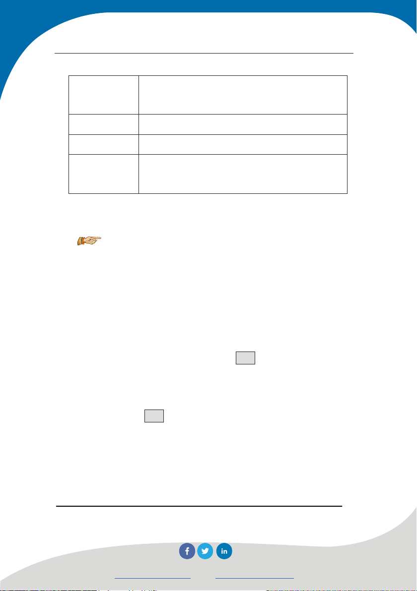
Manual for Multichannel Ultrasonic Pile Integrity Tester
Table 3.2
Number of
List of oblique test profile
pipes
2 X1-2, X2-1
3 X1-2, X2-1, X1-3, X3-1, X2-3, X3-2
4 X1-2, X2-1, X1-3, X3-1, X2-3, X3-2, X1-4, X4-1,
X2-4, X4-2, X3-4, X4-3
Oblique test profile is expressed by “Xm-n”, in which, m means
that the transducer in pipe is up and n means it is down.
NOTE: Oblique test must be implemented based on
flat test; same profile must be tested twice in oblique test. Take
“m-n” profile as example, “Xm-n” (m means that the transducer
in pipe is up and n means it is down) shall be tested at first and
then “Xn-m”.
3. Drawing interface of profile acoustic shadow graph
After oblique test completed, Press Pipe to select profile and
enter into interface as shown in Figure 4.13. Shadow graph will be
drawn automatically after upper limit and lower limit of defect area
have been set. Press Pipe button to switch to other profiles and draw
shadow graph.
86
Novatest S.r.l.
info@novatest.itwww.novatest.it
Page 95

Manual for Multichannel Ultrasonic Pile Integrity Tester
Figure 4.13 Drawing interface of acoustic shadow graph
4. Oblique test check interface
Press Check to enter into check interface, check acoustic
shadow graph of all profiles which have finished oblique test (as
shown in Figure 4.14).
87
Novatest S.r.l.
info@novatest.itwww.novatest.it
Page 96

Manual for Multichannel Ultrasonic Pile Integrity Tester
Figure 4.14 Oblique test check interface
Press Analysis button in this interface to return to drawing
interface of acoustic shadow graph (as shown in Figure 4.13);Sliding toward
right in acoustic shadow graph may switch to check interface of flat
test.
3.3.7 Test next pile
After one pile has been tested, user must create a new pile at
first for testing next pile: In dialogue box of parameter setup, press
New pile button after foundation pile name; refer to Section 4.2.1 for
more details.
88
Novatest S.r.l.
info@novatest.itwww.novatest.it
Page 97

Manual for Multichannel Ultrasonic Pile Integrity Tester
System will clear current data and create new pile file
automatically; before clearing, it will check that whether current data
have been saved. If current data have not been saved yet, prompt box
inquiring “data has been changed, save or not” will pop up, press Yes
button to save it and No for not.
3.4 View switchover
Press View button in main interface to pop up toolbar as shown
in Figure 4.15 for switching views. When the buttons corresponding
to current view and display mode are grey (invalid), other buttons are
valid. If the current view is wave train graph and display mode is 1*6,
the Wavetrain and 1*6 buttons are grey.
Figure 4.15 View switchover toolbar
In all kinds of views, when press graph area, cursor line will
appear, meanwhile × and Ø buttons will pop up at lower right corner
for moving cursor line up and down, pressing once to move one test
point, long press will accelerate the movement.
3.4.1 Bar graph
Press Histogram button to switch to the view of bar graph as
89
Novatest S.r.l.
info@novatest.itwww.novatest.it
Page 98

Manual for Multichannel Ultrasonic Pile Integrity Tester
shown in Figure 4.16, it displays the bar graph composed of
amplitude – depth curve and acoustic speed – depth curve of all test
points in profile, and dynamically real-time refresh in test to enable
user observe the test results of the whole profile at any time. The
upper part of curve corresponds to pile head and lower part
corresponds to pile bottom. The left side displays amplitude – depth
curve, blue represents normal amplitude in this area and red
represents abnormality; the bigger the red area is, the more serious
the abnormality of amplitude is. The right side displays acoustic
speed – depth curve, blue represents normal acoustic speed in this
area and red represents abnormality; the bigger the red area is, the
more serious abnormality of the acoustic speed is.
There is a dark color rectangular block called indication mark of
transducer position in the middle of bar graph, it will move with the
movement of transducer in test to display the position of transducer
in pipe.
When sampling stops, a transverse cursor will appear when
press bar graph area and display waveforms of the pressed test point
in all profiles in single-channel waveform area. If a certain profile has
no data at a certain height, the corresponding single-channel
waveform area will not display waveform.
90
Novatest S.r.l.
info@novatest.itwww.novatest.it
Page 99

Manual for Multichannel Ultrasonic Pile Integrity Tester
Figure 4.16 Bar graph
3.4.2 Curve graph
It may be switched to Curve graph view through View and
display curves such as depth-PSD, depth-acoustic speed and
depth–amplitude of all profiles in the same coordinate system, as
shown in Figure 4.17.
Press a certain position in curve graph area to display elevation
and all parameter values of all profiles at the pressed position; user
may press × and Ø buttons to move cursor, when it is moved a
certain test point, the waveforms of this test point in all profiles will
display in single-channel waveform area.
91
Novatest S.r.l.
info@novatest.itwww.novatest.it
Page 100

Manual for Multichannel Ultrasonic Pile Integrity Tester
Figure 4.17 Curve graph
3.4.3 Wave train graph
Press Wavetrain button to switch to the view of Wave train
graph and display the waveforms of all profiles according to height,
as shown in Figure 4.18.
Press a certain position in wave train graph area to display
waveforms of all profiles at pressed position; press × and Ø buttons
to switch test points or check the wave train graph through sliding
screen up and down.
92
Novatest S.r.l.
info@novatest.itwww.novatest.it
 Loading...