

Page 1

Document Control Number: GSM1001BE001MAN
rr
Enabler-G
Revision History
Rev Date ECN
No.
A 11/19/2001 N/A M. Cutchins /
Author Description
Initial Release
D. Rutledge
User's Manual
CONFIDENTIAL AND PROPRIETARY INFORMATION
Do not duplicate or distribute without express permission from Enfora Inc.
© 2001 Enfora, Inc
Page 2

This manual is copyrighted. All rights are reserved. No portion of this document may be copied,
photocopied, reproduced, translated or reduced to any electronic medium or machine form
without prior consent in writing from Enfora, Inc.
© 2001 Enfora, Inc.
The information in this document is subject to change without notice and does not represent a
commitment on the part of Enfora, Inc.
All product names mentioned in this document are the trademark of their respective owners.
Enfora, Inc.
661 E. 18
th
Street
Plano, Texas 75074-5601
USA
Phone: (972)633-4400
Fax:: (972)633-4444
Technical Support
For problems stemming from your network access, contact your GPRS carrier service.
For technical support and customer service dealing with the modem itself, contact Enfora, inc. by
any of the following methods:
Web site: www.enfora.com
Phone: 972-633-2373
Email: techsupport@enfora.com
Before you contact Technical Support, please have your modem’s Equipment Identifier (EID)
number ready for the Technical Support representative.
CONFIDENTIAL - SEE CONFIDENTIALITY RESTRICTIONS ON TITLE PAGE
Page
2 of 14
Page 3

1.0 Introduction
This document includes a feature overview, product specifications, mechanical information, and basic user
information for Enfora’s Enabler-G, an embedded OEM GPRS Class C modem. This low cost device is
packaged in a small form-factor to facilitate a variety of embedded applications. It offers features and
functions similar to Enfora’s Enabler-A and Spider-O CDPD modems.
2.0 General Description
The Enabler-G is a self-contained General Packet Radio Service (GPRS) Class-C modem containing all
functionality, to include RF and digital control, required to perform wireless data transfer over a GPRS
network. Enabler-G has been designed to work as an embedded component in lap top PCs and other
mobile platforms as well as handheld or portable host devices.
3.0 Safety and Regulatory Compliance
This unit complies with specifications for a GPRS Class-C full-duplex modems with a maximum transmit
output power of 0.6 Watts. This Enabler-G complies with US CFR 47, Part 24 Subpart E and Part 15 of the
FCC Rules and Regulations and Canada RSS-188. Detailed Regulatory and safety statements are provided
following Section 10.0 of this Manual.
Basic safety precautions and guidelines for such devices must be observed, such as:
• Do not expose the device to fire, open flames, or extreme thermal conditions.
• Do not spill liquids on the device.
• Do not disassemble or attempt to modify the device without he express written consent of Enfora.
• Do not attempt to repair the device
The Enabler-G complies with the FCC RF emission and hazard requirements when installed and operated
within the constraints and limitations specified in this manual. Enfora is not liable for injury to personnel
4.0 GPRS Background
General Packet Radio Services (GPRS) is a packet based wireless communication service that can deliver
variable data rates as a function of assigned timeslots and maintain continuous connection to the Internet
for mobile subscribers on Global System for Mobile (GSM) Network worldwide. Since GPRS is based on
GSM communication, it can be single, dual or triple band depending on the area of the service, it will
complement existing services such as circuit switched cellular phone connections and the Short Message
Service (SMS).
In general, GPRS packet-based service should cost users less than circuit-switched services, since their
communication channels are being used on a shared-use, as-packets-are-needed basis rather than dedicated
only to one user at a time. Once GPRS becomes available, mobile users of a virtual private network (VPN)
will be able to access their private networks continuously rather than through a dial-up connection. GPRS
will also complement Bluetooth, a standard for replacing wired connections between devices with wireless
radio connections. In addition to the Internet Protocol (IP), GPRS supports X.25, a packet-based protocol
that is used mainly in Europe and Asia Pacific. GPRS is an evolutionary step toward Enhanced Data GSM
Environment (EDGE) and Universal Mobile Telephone Service (UMTS).
CONFIDENTIAL - SEE CONFIDENTIALITY RESTRICTIONS ON TITLE PAGE
Page
3 of 14
Page 4
The key benefit with GPRS is the ability to sustain a permanent data connection allowing a free flow of
information for the mobile user. The data through put in GPRS will be significantly higher due to the
ability of GPRS mobile terminals to transmit and receive more information than standard GSM terminals.
The GSM communication system, in general, is standardized to operate in multiple bands, primarily, the
900 MHz band which is assigned PGSM, EGSM, RGSM for short, 1800 MHz band which is assigned DCS
and the 1900 MHz band which is assigned PCS. Both the GSM and DCS band are used globally for mobile
voice communication. The PCS 1900 is used in North, Central and South America.
• Enabler-G Model No. GSM0102 900/1800 MHz
• Enabler-G Model No. GSM0103 900/1900 MHz
Although the GSM digital voice standard has existed for well over a decade, it wasn’t until recently that the
demand for wireless data capability has increased. GPRS is a protocol within the GSM standard which was
developed to address the need for data only transmission. Although the GSM voice protocol does support
data transmission, it is limited in data rate due to overhead within the voice protocol. What the GRPS
allows is a faster data rate that is adaptive as well as being packet based.
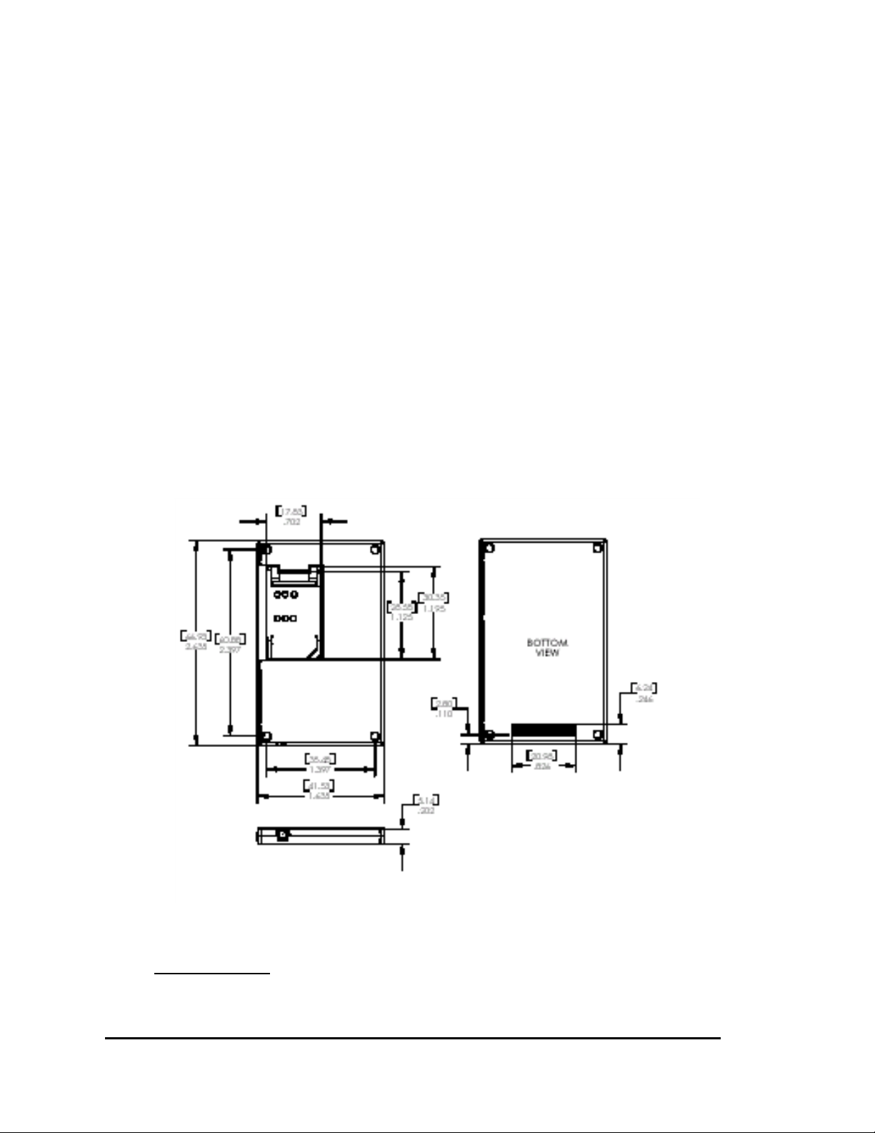
5.0 Mechanical Characteristics
Basic package dimensions and form factor information is provided in the following figures.
5.1 Connectors
Control Connector
The connector used to interface to the host is a 40-position socket header that is 2 rows by 20 columns at 1
mm pitch, part number Samtec CLM-120-02-F-D.
CONFIDENTIAL - SEE CONFIDENTIALITY RESTRICTIONS ON TITLE PAGE
Page
4 of 14
Page 5

RF Connector
The modem’s RF connector is a MMCX jack.
Antennas
The user will supply the antenna. The antenna must have a nominal impedance of 50 Ohms. The VSWR
must be less than 2.0:1. System antenna gain should be 0 to +2 dBi for optimum performance
40 Pin Connector Assignments
Connector pin assignments are shown in the following table.
Table 1
DESCRIPTION I/O REF PIN # REF I/O DESCRIPTION
Ground - GND 1 2 GND - Ground
UART receive I RX 3 4 TX O UART transmit
UART Data carrier
detect
UART Data set ready O DSR 7 8 DTR I UART data terminal
UART Clear to send O CTS 9 10 Ring O UART ring indicator
General Purpose I/O I/O GPIO1 11 12 GPIO2 I/O General Purpose I/O
General Purpose I/O I/O GPIO3 13 14 GPIO4 I/O General Purpose I/O
General Purpose I/O I/O GPIO5 15 16 GPIO6 I/O General Purpose I/O
General Purpose I/O I/O GPIO7 17 18 GPIO8 I/O General Purpose I/O
3.8 volt supply - VCC 19 20 VCC - 3.8 volt supply
3.8 volt supply - VCC 21 22 VCC - 3.8 volt supply
∗ Reserved
∗ Reserved
∗ Reserved
Transmitter is active O TX IND 29 30 ADC_2 I Analog voltage
Wake command I RemoteOn 31 32 Reserved
∗ Reserved
∗ Reserved
∗ Reserved
Ground - GND 39 40 GND - Ground
O DCD 5 6 RTS I UART ready to send
ready
∗
∗
∗
∗
∗
∗
Reserved 23 24 Reserved
Reserved 25 26 Reserved
Reserved 27 28 ADC_1 I Analog voltage
Reserved 33 34 Reserved
Reserved 35 36 Reserved
Reserved 37 38 Reserved
∗
∗
∗
∗
∗
∗
∗ Reserved
∗ Reserved
monitoring
monitoring
∗ Reserved
∗ Reserved
∗ Reserved
∗ Reserved
6.0 Electrical Characteristics
6.1 Input Voltage and Power
The modem operates from an input voltage range of 3.15 Vdc to 4.50 Vdc. Input voltage may be directly
applied from a 3.6V Li-Ion or Nickel Metal Hydride battery. The digital input and output signals are 3.3
Vdc tolerant.
CONFIDENTIAL - SEE CONFIDENTIALITY RESTRICTIONS ON TITLE PAGE
Page
5 of 14
Page 6

6.2 Power Consumption
The modem has four power consumption modes:
Transmit @ 28 dBm < 1000 mA < 3300 mW
The modem has three hardware sections. Each is powered separately. These hardware sections are (a) the
digital circuitry, (b) the RF receiver circuitry, and (c) the RF transmitter circuitry. The following chart
describes which sections are powered on during each power consumption mode.
Mode Digital Circuitry
Off/ Standby Off Off Off
Sleep Low power most of time Off most of time Off
Receive On On Off most of time
Transmit On On On
Modem Off/ Standby Mode
In the Modem Off mode, a FET switch inside the modem is turned off. All power within the modem is
removed. A WAKE command or power cycle is required to come back to functional status.
allows the unit to be put in deep sleep. A WAKE command or power cycle is required to return to
functional status
Sleep Mode
Sleep mode is defined by the GPRS specification. If Sleep mode is enabled (user option), the modem will
enter Sleep mode after a user-specified period of time if there is no IP data traffic across the serial port. The
modem then disables its RF receiver, disables its RF transmitter, and places the digital circuitry in a low
power state for the sleep timeout period negotiated with the GPRS network (typically 60-90 seconds). The
modem will enable its RF receiver and digital circuitry after the specified sleep timeout and check if any
new message is waiting from the GPRS network. If no new message is available, the modem disables its
circuitry and returns to sleep for the specified timeout period before waking up again. If a new message is
available from the GPRS network, the modem remains in Receive mode and reads the message. After
receiving a message, the modem will remain in Receive mode until the next period of serial port inactivity
occurs. If the host computer sends a message to the serial port, the modem immediately exits Sleep mode,
returns to Transmit mode, and transmits the message to the GPRS network.
Receive Mode
The unit is in Receive mode anytime it is trying to register or maintaining registration but has no data to
transmit. During this mode, the transmit circuit is turned off, but the receive circuitry is turned on. The
GPRS protocol requires occasional transmit bursts to maintain registration even if no data traffic is
occurring.
Transmit Mode
During Transmit mode, the modem is fully operational. The transmitter and receiver are both on since the
unit is a full duplex modem. The transmit power required varies based on the received signal power.
Mode Current Power @ 3.3 Vdc Input
Off/Stand-by
Sleep < 5 mA < 16.5 mW
Receive < 150 mA < 495 mW
< 100 µA < 330 µW
RF Receiver
RF Transmitter
Circuitry
Circuitry
.
Standby mode
CONFIDENTIAL - SEE CONFIDENTIALITY RESTRICTIONS ON TITLE PAGE
Page
6 of 14
Page 7

Transmit power level varies based upon the proximity of the modem to the cell site, RSSI measured by the
modem, and maximum power level allowed by the cell site.
7.0 Radio Performance
The following table shows the standard channel allocation for the EGSM 900 and PCS 1900 band. The EGSM
transmitter transmits at exactly 45 MHz below the receive frequency. The PCS transmitter transmit at exactly 80
MHz below the its received frequency.
Channel Number for E-GSM 900
(0-124)
Channel 0 890.0MHz 935.0MHz
Channel 31 896.2 MHz 941.2 MHz
Channel 62 902.4 MHz 947.4 MHz
Channel 93 908.6 MHz 953.6 MHz
Channel 124 914.8 MHz 959.8 MHz
Channel Number for E-GSM 900
(975-1023)
Channel 975 880.2 MHz 925.2 MHz
Channel 1000 885.2 MHz 930.2 MHz
Channel 1023 889.8 MHz 934.8 MHz
MS Tx Band
Ch 955 Ch1023 Ch 0 Ch 62 Ch 124
876.2 MHz 889.8MHz 890.0 MHz 902.4 MHz 914.8 MHz
MS Rx Band
Ch 955 Ch 1023 Ch 0 Ch 62 Ch 124
921.2 MHz 934.8 MHz 935.0 MHz 947.4 MHz 959.8 MHz
Channel Number for PCS 1900
(512-810)
Channel 512 1850.2 MHz 1930.2 MHz
Channel 587 1865.2 MHz 1945.2 MHz
Channel 662 1880.2 MHz 1960.2 MHz
Channel 737 1895.2 MHz 1975.2 MHz
Channel 810 1909.8 MHz 1989.8 MHz
MS Tx Band
Ch 512 Ch 662 Ch 810
1850.2 MHz 1880.2 MHz 1909.8 MHz
MS Rx Band
Ch 512 Ch 699 Ch 885
1930.2 MHz 1960.2 MHz 1989.8 MHz
The primary advantage of the GSM standard is that, regardless of the band of operation, they all share the same
technical features. This specification applies to the GSM voice, voice & data, and data only (GPRS) transmission.
With TDMA, one GSM RF channel can support up to 8 mobile users simultaneously. Each user is allowed to
transmit once every frame period for a 1 timeslot duration. Because of the TDMA scheme, timing accuracy in the
software and hardware implementation is very critical. The Enabler has the following common specifications.
Mobile Station Transmit Frequency
= 890 MHz + 0.2(n)
Mobile Station Transmit Frequency
= 890 MHz + 0.2(n-1024)
Mobile Station Transmit Frequency
= 1850.2MHz + 0.2(n-512)
Mobile Station Receive Frequency
= 890 MHz + 0.2(n) + 45 MHz
Mobile Station Receive Frequency
= 890 MHz + 0.2(n-1024) + 45 MHz
Mobile Station Receive Frequency
= 1850.2MHz + 0.2(n-512) + 80 MHz
CONFIDENTIAL - SEE CONFIDENTIALITY RESTRICTIONS ON TITLE PAGE
Page
7 of 14
Page 8

Key Technical Feature
Modulation Data Rate 270.833Kbit/s
Bit Period 3.692 us
TDMA Timeslot 8 timeslot / RF channel
1 Timeslot Period 576.9 us
Bits/timeslot 156.25 bits
Timeslot Composition 148 (data bits) + 8.25 (guard bits)
Timeslot Allocation 0 to 7
Frame Period 4.615 ms (8 timeslot period)
Channel Spacing 200 KHz
Modulation Scheme 0.3 GMSK
Specification
8.0 Monitoring
Monitoring the state of the modem may be done both locally and remotely. This is accomplished by using
the UDP API to monitor configuration settings, GPIO states, and A to D measurements. Modification to
the modem’s configuration settings and GPIO outputs states is also facilitated through the UDP API.
8.1 Temperature
The temperature of the Modem is monitored internally by an analog input. When the temperature exceeds
the specified range, the operator is notified through the Modem Manager.
8.2 Host Voltage
The voltage being supplied to the Host is monitored internally by an analog input. When the supply
voltage exceeds the specified range the operator is notified through the Modem Manager and RF
transmission is suspended.
9.0 Control Connector Signal Descriptions
9.1 Serial Interface
The modem provides a standard 16550 UART serial interface to the host. It provides a full 9-pin, RS-232
interface at logic level (3.3 V). TxData is the serial data from the modem. RxData is the serial data from the
host to the modem. This data may contain 7 or 8 data bits, and 1 stop bit. The baud rate may be adjusted to
19200 or 38400 bits per second. Default settings are 8 data, 1 stop, no parity, and 38400 baud. DCD may
be set to be always on or to indicate GPRS connection status. DTR may be used to force the modem into
AT command mode from online data mode. RTS and CTS may be used for hardware handshaking. DSR is
always active (connected to ground) while the modem is on. RING may be used to alert the host to
incoming messages by pulsing when the modem is in sleep state and a new message arrives from the
network. For a minimal implementation, connect RxData and TxData to the COM port serial data lines,
connect DTR and RTS to GND.
9.2 GPIO
Eight general-purpose signals (GPIO1-8) are provided. Each of these signals may be selected as inputs or
outputs. They may be used independently as a user-specified function, or may be used to provide modem
CONFIDENTIAL - SEE CONFIDENTIALITY RESTRICTIONS ON TITLE PAGE
Page
8 of 14
Page 9

control and status signals. Two examples of modem control signals are: register/deregister on GPRS
network command and transmitter disable. One modem status signal example is GPRS registration status.
These GPIO pins are controlled with AT commands and/or by the UDP control interface. GPIO signals
will only be active when the modem is in receive or transmit power consumption mode.
9.3 Wake Circuit
The WAKE signal is used to wake the modem up from sleep.
9.4 A-to-D Inputs
Two analog-to-digital conversion signals are provided for the user; ADC1 and ADC2. The binary
resolution is 8 bits that have a readable input voltage range of 3.0 to 3.2V. These signals may be read with
AT commands or the API control interface.
9.5 Transmit Indicator (TX IND)
The transmit indicator output alerts the Host when the modem is in transmit mode. The transmitter
indicator will be high when the modem is in transmit mode.
10.0 Software
10.1 Operating Systems
The Enabler-G Host Modem Manager software supports Windows CE 3.0 (Windows for Pocket PC 2000)
and Windows 98 Second Edition. Future versions of the Enabler-G Modem Manager will support other
Windows operating systems.
10.2 Modem Manager
The Enabler-G Modem Manager will allow configuration of the modems parameters as well as real time
monitoring of the GPRS network details such as sensitivity and channel.
The Modem manager will also automatically detect the modem when the application is launched.
10.3 Communication Protocol
Enabler-G supports a common AT command set, ICMP, and UDP PAD. Enabler-G also supports TCP/IP,
and SLIP protocols initiated through Dial-Up networking. With this configuration, Internet Explorer,
Netscape, MS Outlook, and other TCP/IP protocol based applications are supported by the modem.
11.0 Environmental Characteristics
11.1 Temperature
-20oC to 700C, operating
-40oC to 850C, non-operating
11.2 Altitude
15,000 feet, operating
45,000 feet, non-operating
CONFIDENTIAL - SEE CONFIDENTIALITY RESTRICTIONS ON TITLE PAGE
Page
9 of 14
Page 10

11.3 Humidity
5-95% non-condensing
11.4 Vibration
Sinusoidal Random
Amplitude 1.5G pp 1.5G rms
Freq. Range 10-500 Hz 10-500 Hz
Freq. Sweep Rate .5 octave/min, linear
Duration 2 hours per axis 1 hour per axis
Sinusoidal Random
Amplitude 3G pp 3G rms
Freq. Range 5-500 Hz 10-500 Hz
Freq. Sweep Rate .5 octave/min, linear
Duration 2 hours per axis 1 hour per axis
11.5 Shock
Operating Non-Operating
Amplitude 10G 80G
Wave Form ½ sine, 11 msec.
Repetitions 6 per axis 6 per axis
11.6 Electrostatic Discharge
The Enabler-G is compliant with EN50082-1 and IEC801-2 (Level 4), and can withstand an 8 kV discharge
from a 180 pF/300 Ohm source probe without sustaining any hard failures. The discharge is performed
with the card installed on a host board and the voltage is discharged at user accessible points.
Operating
Non-Operating
½ sine, 11msec. Duration
duration
CONFIDENTIAL - SEE CONFIDENTIALITY RESTRICTIONS ON TITLE PAGE
Page
10 of 14
Page 11

12.0 Regulatory Information
FCC REGULATORY COMPLIANCE
INTEGRATION AND USE INFORMATION
INTEGRATION CONSIDERATIONS AND INSTALLATION REQUIREMENTS
The Enabler-G OEM GPRS modem is designed for use in a variety of host units, "enabling" the host platform to
perform wireless data communications. However, there are certain criteria relative to integrating the modem into a
host platform such as a PC, laptop, handheld or PocketPC, monitor and control unit, etc. that must be considered to
ensure continued compliance with FCC compliance requirements.
The modem was tested and certified to meet FCC Parts 15 and 24 in a stand-alone configuration, demonstrating that
the Enabler-G complies with Part 15 emission limits regardless of the device into which it may be installed. Further,
to provide relief in certain applications for the host integrator, the Enabler-G was approved under the "modular
approval" process for a transmitter. This approach, described by FCC Public Notice DA 00-131407 released June
26, 2000, is intended to afford relief to equipment manufacturers by eliminating the requirement for obtaining a new
equipment authorization for the same transmitter when installed in a new device.
However, the host platform integrator must follow all installation instructions and cautionary information necessary
to comply with FCC RF exposure requirements.
In order to use the Enabler-G without additional FCC certification approvals, the installation must meet the
following conditions. Otherwise, additional FCC approvals must be obtained.
1. “Fixed” and “mobile” applications: At least 20 cm (7.9 in.) separation distance between the antenna and
the user’s body must be maintained at all times. For the transmitter to meet the MPE categorical exclusion
requirements of 2.1091, the ERP must be less than 1.5 watts for personnel separation distance of at least 20
cm (7.9 in).
a. In “Fixed” applications, antenna gain is limited to a maximum of 7 dBi, with a corresponding
Equivalent isotropic Radiated Power (EIRP) of 37 dBm / 5 W.
b. In “mobile” applications, antenna gain is limited to a maximum of 3 dBi, with a corresponding
Equivalent isotropic Radiated Power (EIRP) of 37 dBm /25 W
c. If greater than 1.5 watts exists, then additional testing and FCC approval is required (e.g., see 3 below).
2. If used with a desktop or other application where the antenna can be easily relocated to meet the 20 cm
criteria, then this is considered a “mobile” application.
If used in a "mobile" application where the antenna is normally separated at least 20 cm (7.9 in) from the
human body during device operation, then an appropriate warning label must be placed on the host unit
adjacent to the antenna.
The label should contain a statement such as the following:
WARNING
RF exposure. Keep at least 20 cm
(7.9 in) separation distance from
the antenna and the human body.
3. “Portable” applications: If used in a "portable" application such as a handheld device with the antenna
less than 20 cm (7.9 in.) from the human body when the device is operating, then the integrator is
responsible for passing additional "as installed" testing.
CONFIDENTIAL - SEE CONFIDENTIALITY RESTRICTIONS ON TITLE PAGE
Page
11 of 14
Page 12

Separate FCC approval for RF exposure compliance is required for end products that do not met the
separation or maximum antenna gain criteria.
a. SAR (Specific Absorption Rate) testing, with results submitted to the FCC for approval prior to selling
the integrated unit. If unable to meet SAR requirements, then the host unit must be restricted to
"mobile" use (see 3 below).
b. Unintentional emissions, FCC Part 15; results do not have to be submitted to the FCC unless
requested, although the test provides substantiation for required labeling (see 5 below).
4. Host unit user manuals and other documentation must also include appropriate caution and warning
statements and information.
5. If the FCC ID for the modem is not visible when installed in the host platform, then a permanently attached
or marked label must be displayed on the host unit referring to the enclosed modem. For example, the label
should contain wording such as:
Contains CDPD modem transmitter module
This device complies with Part 15 of the FCC Rules.
Operation is subject to the following two conditions:
(1) This device may not cause harmful interference,
and (2) This device must accept any interference
received, including interference that may cause
undesired operation.
FCC ID: MIVGSM0103
or
Contains FCC ID: MIVGSM0103
This device complies with Part 15 of the FCC Rules.
Operation is subject to the following two conditions:
(1) This device may not cause harmful interference,
and (2) This device must accept any interference
received, including interference that may cause
undesired operation.
6. Any antenna used with the modem must be approved by the FCC as either a Class II Permissive Change
(including MPEL or SAR data as applicable). The "professional installation" provision of FCC Part 15.203
does not apply.
7. The transmitter and antenna must not be co-located or operating in conjunction with any other antenna or
transmitter. Violation of this would allow a user to plug another transmitter in to the product and
potentially create an RF exposure condition.
WARNING
The transmitter and antenna must not be colocated or operating in conjunction with any
other antenna or transmitter. Failure to observe
this warning could produce an RF exposure
condition.
CONFIDENTIAL - SEE CONFIDENTIALITY RESTRICTIONS ON TITLE PAGE
Page
12 of 14
Page 13

Regulatory Information (Continued)
The equipment certifications appropriate to your device are marked on the device and product specific information.
The use of the equipment is subject to the following conditions:
FCC COMPLIANCE STATEMENT
This device complies with Part 15 of FCC Rules of operation subject to the condition that this device does
not cause harmful interference. This device also complies with FCC Part 24.
WARNING
This device has been tested to determine compliance with FCC RF exposure requirements. It has been
found to comply with Maximum Permissible Exposure limits (MPEL) requirements for uncontrolled
exposure at 20 cm (7.9 in.) or greater.
CAUTION
Since this is an OEM device, and since variables such as the interfacing antenna may affect performance
characteristics, it is incumbent upon the host platform integrator to ensure the integrated system maintains
compliance with FCC regulations.
CAUTION
Changes or modifications without the express consent of Enfora, Inc. voids the user’s authority to use the
equipment.
This equipment has been tested and found to comply with the limits pursuant to Part 15 Subpart B and Part 24 of the
FCC rules. These limits are designed to provide reasonable protection against harmful interference in an appropriate
installation. This equipment generates, uses, and can radiate radio frequency energy and, if not used in accordance
with instructions, can cause harmful radiation to radio communication. However, there is no guarantee that
interference will not occur in a particular installation. If the equipment does cause harmful interference in radio and
television reception, which can be determined by turning the equipment on and off, the user is encouraged to try to
correct the interference by one or more of the following measures:
• Reorient or relocate the receiving antenna
• Increase the separation distance between the equipment and the receiver
• Contact Enfora, Inc. Technical Support for assistance.
INDUSTRY CANADA COMPLIANCE
This digital apparatus does not exceed Class B limits for radio noise emissions or electromagnetic interference
(EMI) from digital apparatus as set out in the interference-causing equipment requirements of Industry Canada.
CONFIDENTIAL - SEE CONFIDENTIALITY RESTRICTIONS ON TITLE PAGE
Page
13 of 14
Page 14

WARRANTY
The Enabler-G is covered by a 36-Month Limited Warranty.
Enfora, Inc. warrants the products that it manufactures to be free from defects in materials and
workmanship for a period of 36 months from the date of shipment from Enfora. This warranty is
limited to the original purchaser of the product and is not transferable.
During the 36-month warranty period, Enfora will repair or replace, at its option, any defective
products or parts at no additional charge provided that the product is returned, shipping prepaid,
to Enfora. The purchaser is responsible for insuring any product so returned and assumes the risk
of loss during shipping. All replaced parts become the property of Enfora.
During the 36-month warranty period, Enfora will also provide any software maintenance
releases at no additional charge.
THIS LIMITED WARRANTY DOES NOT EXTEND TO ANY PRODUCT THAT HAS BEEN
DAMAGED AS A RESULT OF ACCIDENT, MISUSE, ABUSE, OR AS A RESULT OF
SERVICE OR MODIFICATION BY ANYONE OTHER THAN ENFORA.
EXCEPT AS EXPRESSLY SET FORTH ABOVE, NO OTHER WARRANTIES ARE
EXPRESSED OR IMPLIED, INCLUDING BUT NOT LIMITED TO, ANY IMPLIED
WARRANTIES OF MERCHANTABILITY AND FITNESS FOR A PARTICULAR
PURPOSE, AND ENFORA EXPRESSLY DISCLAIMS ALL WARRANTIES NOT STATED
HEREIN. AS WARRANTED ABOVE, THE PURCHASER’S SOLE REMEDY SHALL BE
REPAIR OR REPLACEMENT AS PROVIDED ABOVE. UNDER NO CIRCUMSTANCES
WILL ENFORA BE LIABLE TO THE PURCHASER OR ANY USER FOR ANY DAMAGES,
INCLUDING ANY INCIDENTAL OR CONSEQUENTIAL DAMAGES, EXPENSES, LOST
PROFITS, LOST SAVINGS, OR OTHER DAMAGES ARISING OUT OF THE USE OF OR
INABILITY TO USE THE PRODUCT.
CONFIDENTIAL - SEE CONFIDENTIALITY RESTRICTIONS ON TITLE PAGE
Page
14 of 14
 Loading...