

Novatel SPAN-SE User Manual

USER MANUAL
SPAN-SE
OM-20000124 Rev 1

Proprietary Notice
SPAN-SE Technology for OEMV User Manual
Publication Number: OM-20000124
Revision Level: 1
Revision Date: 2008/03/25
This manual reflects SPAN-SE firmware Version SPPC 1.000 and OEMV firmware Version 3.621.
Proprietary Notice
Information in this document is subject to change without notice and does not represent a commitment
on the part of NovAtel Inc. The software described in this document is furnished under a licence
agreement or non-disclosure agreement. The software may be used or copied only in accordance with
the terms of the agreement. It is against the law to copy the software on any medium except as
specifically allowed in the license or non-disclosure agreement.
No part of this manual may be reproduced or transmitted in any form or by any means, electronic or
mechanical, including photocopying and recording, for any purpose without the express written
permission of a duly authorized representative of NovAtel Inc.
The information contained within this manual is believed to be true and correct at the time of
publication.
NovAtel, OEMV, CDU, ProPak, RT-20 and RT-2 are registered trademarks of NovAtel Inc.
SPAN Technology, SPAN-SE, DL-V3, ProPak-V3, and PAC are trademarks of NovAtel Inc.
All other product or brand names are trademarks of their respective holders.
Manufactured and protected under U.S. Patent:
Narrow Correlator Position for Velocity Kalman Filter
#5,101,416 #6,664,923 B1
#5,390,207 #7,193,559 B2
#5,495,499 SPAN Technology
#5,809,064 #6,721,657 B2
PAC Correlator #6,750,816 B1
#6,243,409 B1 10/758,363 (pending)
#5,414,729 10/932,497 (pending)
Dual Frequency GPS #
#5,736,961
Anti-Jamming Technology
#5,734,674
7,346,452
© Copyright 2009 Novatel Inc. All rights reserved. Unpublished rights reserved
under International copyright laws. Printed in Canada on recycled paper. Recyclable.
2 SPAN-SE User Manual Rev 1

Table of Contents
Proprietary Notice 2
Software License 11
Terms and Conditions 13
Warranty Policy 16
Customer Service 18
Notices 19
Foreword 20
1 Introduction 22
1.1 Fundamentals of GNSS/INS...........................................................................................23
1.2 Models and Features......................................................................................................24
2 SPAN-SE Installation 26
2.1 SPAN-SE Hardware Description ....................................................................................26
2.2 SPAN-SE Hardware Installation.....................................................................................29
2.2.1 Mount Antenna.....................................................................................................29
2.2.2 Mount IMU............................................................................................................30
2.2.3 Connect Interface Cables.....................................................................................30
2.2.4 Connect Power.....................................................................................................31
2.2.5 Power Button........................................................................................................32
3 SPAN-SE Operation 34
3.1 Definition of Reference Frames Within SPAN................................................................34
3.1.1 The Local-Level Frame (ENU)..............................................................................34
3.1.2 The SPAN Computation Frame............................................................................34
3.1.3 The Enclosure Frame........................................................................................... 35
3.1.4 The Vehicle Frame............................................................................... ................35
3.2 Communicating with the SPAN System..........................................................................36
3.2.1 INS Window in CDU.............................................................................................38
3.3 Software Configuration...................................................................................................39
3.3.1 GNSS Configuration.............................................................................................39
3.3.2 SPAN IMU Configuration................................................................... ...................40
3.4 Real-Time Operation ......................................................................................................43
3.4.1 Configuration for Alignment..................................................................................44
3.4.2 INS Configuration Command Summary...............................................................44
3.4.3 System Start-Up and Alignment Techniques........................................................44
3.4.4 Navigation Mode...................................................................................................46
3.4.5 Data Collection.....................................................................................................46
3.4.6 Lever Arm Calibration Routine .............................................................................47
3.4.7 Vehicle to SPAN frame Angular Offsets Calibration Routine ...............................48
3.5 SPAN Wheel Sensor Configuration................................................................................49
3.5.1 Wheel Sensor Updates Using the Event Input Lines............................................49
3.5.2 Wheel Sensor Updates using the iIMU-FSAS IMU ..............................................50
3.5.3 Wheel Sensor Updates using the WHEELVELOCITY Command........................50
3.5.4 Logging Wheel Sensor Data from SPAN-SE........................................................50
3.6 Data Collection for Post Processing...............................................................................51
3.7 Status Indicators.............................................................................................................52
SPAN-SE User Manual Rev 1 3

3.8 The SD Card...................................................................................................................53
3.9 Logging Data to the SD Card..........................................................................................53
3.9.1 Insert the SD Card................................................................................................53
3.9.2 Prepare the Card..................................................................................................54
3.9.3 Select Logs to Send to the SD Card.....................................................................55
3.9.4 Start and Stop Logging.........................................................................................55
3.9.5 Log a Pre-Defined List of Logs.............................................................................55
3.9.6 Auto-Logging on Start-Up.....................................................................................56
3.9.7 Reading data from the card................................................... ...............................56
3.10 Synchronizing External Equipment...............................................................................57
3.10.1 Configuring a Synchronous Output Pulse...........................................................57
3.10.2 Configuring an Input Strobe................................................................................58
3.11 SPAN-SE Ethernet Connection ....................................................................................59
3.11.1 Configuring for TCP or UDP Operation ..............................................................59
3.11.2 Configuring the Ethernet Connection Settings....................................................60
3.11.3 Configuring Log Requests Destined for the Ethernet Port..................................60
3.11.4 Connecting to the Ethernet Port .........................................................................60
Appendices
A Technical Specifications 61
A.1 SPAN-SE........................................................................................................................61
A.1.1 SPAN-SE Receiver ..............................................................................................61
A.2 Inertial Measurement Units (IMUs).................................................................................69
A.2.1 LN-200 IMU..........................................................................................................69
A.2.2 iIMU-FSAS ..................................................... ... .................................. .................74
A.2.3 HG1700 IMU ................................................................ ... .....................................83
B Commands 86
B.1 Command Formats...................................................... .................................. .................86
B.2 Using a Command as a Log...........................................................................................86
B.3 DOS Commands ............................................................................................................87
B.3.1 DIR - Show Directory......................................................................................... ...88
B.3.2 CD - Change Directory.......................................................... ... .. ..........................88
B.3.3 FORMAT - Format storage medium.....................................................................88
B.3.4 MKDIR - Make Directory ......................................................................................88
B.3.5 RMDIR - Remove Directory..................................................................................88
B.3.6 PWD - Present Working Directory........................................................................89
B.3.7 FTP................................................................. .................................. ....................89
B.4 SPAN-SE Command Reference.....................................................................................89
B.4.1 APPLYVEHICLEBODYROTATION Enable vehicle to body rotation.................90
B.4.2 ASSIGNLBAND Set L-band satellite communication parameters.....................91
B.4.3 COM Port configuration control .........................................................................94
B.4.4 COMCONTROL Control the RS232 hardware control lines..............................97
B.4.5 COMVOUT Turn power to the ports on or off....................................................100
B.4.6 EVENTINCONTROL Control mark input properties ..........................................101
B.4.7 EVENTOUTCONTROL Control PPS signal properties .....................................102
B.4.8 FORMAT Format the SD Card .........................................................................103
B.4.9 FRESET Factory reset.......................................................................................104
B.4.10 GNSSCARDCONFIG GNSS port configuration ..............................................105
B.4.11 IFCONFIG Set IP information..........................................................................107
4 SPAN-SE User Manual Rev 1

B.4.12 INSCOMMAND INS control command............................................................108
B.4.13 INSZUPT Request Zero Velocity Update ........................................................109
B.4.14 LEVERARMCALIBRATE INS Calibration Command......................................110
B.4.15 LOG Request logs from the receiver............................................................... 112
B.4.16 LOGFILE Log Data to a File on the SD Card..................................................117
B.4.17 NMEATALKER Set the NMEA Talker ID.........................................................118
B.4.18 PSRDIFFSOURCE Set the pseudorange correction source...........................119
B.4.19 RESET Perform a hardware reset................................................................... 122
B.4.20 RTKCOMMAND Reset or set the RTK filter to its defaults..............................123
B.4.21 RTKDYNAMICS Set the RTK dynamics mode................................................124
B.4.22 RTKSOURCE Set the RTK correction source.................................................125
B.4.23 RVBCALIBRATE Vehicle to Body Rotation Control........................................127
B.4.24 SAVECONFIG Save current configuration in NVM.........................................128
B.4.25 SBASCONTROL Set SBAS test mode and PRN............................................129
B.4.26 SETAUTOLOGGING Start SD Card Logging at Boot-Up ...............................131
B.4.27 SETETHPROTOCOL Set Eth1 Protocol.........................................................132
B.4.28 SETIMUORIENTATION Set IMU Orientation..................................................133
B.4.29 SETIMUTOANTOFFSET Set IMU to antenna offset.......................................136
B.4.30 SETIMUTYPE Set IMU type............................................................................137
B.4.31 SETINITATTITUDE Set initial attitude of SPAN in degrees ............................139
B.4.32 SETINITAZIMUTH Set initial azimuth and standard deviation........................141
B.4.33 SETINSOFFSET Set INS offset......................................................................143
B.4.34 SETMARK1OFFSET, SETMARK2OFFSET, SETMARK3OFFSET,
SETMARK4OFFSET Set Mark offset..............................................................144
B.4.35 SETWHEELPARAMETERS Set wheel parameters........................................145
B.4.36 SOFTPOWER Power down the SPAN-SE......................................................147
B.4.37 SPANAUTH Add an authorization code for a new model..................................148
B.4.38 SPANMODEL Switch to a previously authorized model..................................150
B.4.39 UNLOG Remove a log from logging control....................................................151
B.4.40 UNLOGALL Remove all logs from logging control ..........................................153
B.4.41 VEHICLEBODYROTATION Vehicle to SPAN frame rotation..........................154
B.4.42 WHEELVELOCITY Wheel velocity for INS augmentation...............................156
C Data Logs 157
C.1 Log Types ......................................................................................................................157
C.1.1 ASCII....................................................................................................................159
C.1.2 Binary...................................................................................................................161
C.1.3 GPS Time Status.................................................................................................164
C.1.4 Message Time Stamps........................................................................................165
C.1.5 Log Type Examples.............................................................................................166
C.2 Description of ASCII and Binary Logs with Short Headers............................................167
C.3 NMEA Standard Logs ....................................................................................................168
C.4 SPAN-SE Logs...............................................................................................................170
C.4.1 BESTPOS Best Position and BESTGPSPOS Best GPS Position...................171
C.4.2 BESTVEL Best Available Velocity Data and BESTGPSVEL
Best Available GPS Velocity Data.......................................................................175
C.4.3 BESTLEVERARM IMU to Antenna Lever Arm..................................................177
C.4.4 COMCONFIG Current COM Port Configuration.............................................. ..178
C.4.5 COMPROTOCOL COM Port Protocol...............................................................180
C.4.6 DIRENT SD Card File List.................................................................................181
C.4.7 GLOCLOCK GLONASS Clock Information.......................................................182
C.4.8 GLOEPHEMERIS GLONASS Ephemeris Data ................................................184
SPAN-SE User Manual Rev 1 5

C.4.9 GLORAWEPHEM Raw GLONASS Ephemeris Data ........................................188
C.4.10 GPALM Almanac Data ....................................................................................189
C.4.11 GPGGA GPS Fix Data and Undulation...........................................................191
C.4.12 GPGLL Geographic Position...........................................................................194
C.4.13 GPGRS GPS Range Residuals for Each Satellite ..........................................196
C.4.14 GPGSA GPS DOP and Active Satellites.........................................................198
C.4.15 GPGST Pseudorange Measurement Noise Statistics.....................................200
C.4.16 GPGSV GPS Satellites in View.......................................................................202
C.4.17 GPVTG Track Made Good And Ground Speed ..............................................204
C.4.18 GPZDA UTC Time and Date ...........................................................................205
C.4.19 INSATT INS Attitude........................................................................................206
C.4.20 INSATTS Short INS Attitude............................................................................207
C.4.21 INSCOV INS Covariance Matrices............................................................... ...208
C.4.22 INSCOVS Short INS Covariance Log..............................................................210
C.4.23 INSPOS INS Position......................................................................................211
C.4.24 INSPOSS Short INS Position..........................................................................212
C.4.25 INSPOSSYNC Time Synchronised INS Position ............................................213
C.4.26 INSPVA INS Position, Velocity and Attitude....................................................214
C.4.27 INSPVAS Short INS Position, Velocity and Attitude........................................215
C.4.28 INSSPD INS Speed.........................................................................................216
C.4.29 INSSPDS Short INS Speed.............................................................................217
C.4.30 INSUPDATE INS Update ................................................................................218
C.4.31 INSVEL INS Velocity.......................................................................................220
C.4.32 INSVELS Short INS Velocity...........................................................................221
C.4.33 LBANDINFO L-band Configuration Information ..............................................222
C.4.34 LBANDSTAT L-band Status Information.........................................................224
C.4.35 LOGLIST List of System Logs.........................................................................230
C.4.36 MAC MAC Address .........................................................................................233
C.4.37 MARK1COUNT, MARK2COUNT, MARK3COUNT, MARK4COUNT
Mark Count ........................................................................................................234
C.4.38 MARK1PVA, MARK2PVA, MARK3PVA, MARK4PVA
Position, Velocity and Attitude at Mark ..............................................................235
C.4.39 MARK1TIME, MARK2TIME, MARK3TIME, MARK4TIME
Time of Mark Input Event................................ ... ... ....................................... ......236
C.4.40 PORTSTATS Port Statistic..............................................................................238
C.4.41 RANGE Satellite Range Information ...............................................................240
C.4.42 RANGECMP Compressed Version of the RANGE Log ..................................244
C.4.43 RAWEPHEM Raw Ephemeris.........................................................................246
C.4.44 RAWIMU Raw IMU Data.................................................................................247
C.4.45 RAWIMUS Short Raw IMU Data ....................................................... ..............252
C.4.46 RXCONFIG Receiver Configuration................................................................254
C.4.47 RXSTATUS Receiver Status...........................................................................256
C.4.48 RXSTATUSEVENT Status Event Indicator .....................................................263
C.4.49 SPANVALIDMODELS Valid Model Information ..............................................265
C.4.50 TIME Time Data ..............................................................................................266
C.4.51 TIMEDWHEELDATA Timed Wheel Data........................................................268
C.4.52 VEHICLEBODYROTATION Vehicle to SPAN Frame Rotation.........................269
C.4.53 VERSION Version Information........................................................................270
C.4.54 WHEELSIZE Wheel Size.................................................................................273
D Command Prompt Interface 274
D.1 DOS................................................................................................................................275
6 SPAN-SE User Manual Rev 1

D.2 Windows.........................................................................................................................276
E HG1700 IMU Installation 277
E.1 Disassemble the SPAN IMU Enclosure .........................................................................278
E.2 Install the HG1700 Sensor Unit......................................................................................279
E.3 Make the Electrical Connections...................................................... ..............................280
E.4 Re-Assemble the SPAN IMU Enclosure ................................................................. .. ... ..281
F LN-200 IMU Installation 282
F.1 Disassemble the SPAN IMU Enclosure..........................................................................283
F.2 Install the LN-200 Sensor Unit........................................................................................284
F.3 Make the Electrical Connections....................................................................................285
F.4 Re-Assemble the SPAN IMU Enclosure.........................................................................286
G Frequently Asked Questions 287
H Replacement Parts 289
H.1 SPAN System ................................................................................................................289
H.2 Accessories and Options ...............................................................................................289
H.3 Manufacturer’s Part Numbers........................................................................................290
Index 291
SPAN-SE User Manual Rev 1 7

Figures
1 SPAN-SE Receiver .......................................................................................................22
2 SPAN System IMUs ......................................................................................................22
3 Basic SPAN-SE Set-Up ................................................................................................27
4 SD Memory Card ..........................................................................................................28
5 Receiver Enclosure Back Panel ...................................................................................28
6 SPAN-SW Power Button ..............................................................................................32
7 Local-Level Frame (ENU) ...................................................... .......................................34
8 The Enclosure Frame ...................................................................................................35
9 Vehicle Frame ..............................................................................................................36
10 SPAN-SE LED Indicators .............................................................................................52
11 SD Card Access Door ...................................................................................................53
12 Event Out ................................................... .. .................................. ...............................58
13 SPAN-SE Power Cable ................................................................................................64
14 SPAN-SE I/O 1 Green Cable ........................................................................................65
15 SPAN-SE I/O 2 Yellow Cable .......................................................................................67
16 LN-200 IMU Enclosure Top/Bottom Dimensions and Centre of Navigation .................69
17 LN-200 Enclosure Side Dimensions .............................................................................70
18 LN-200 Interface Cable ................................................................................................71
19 IMU Interface Cable Pin-Out (ProPak-V3) ....................................................................71
20 LN-200 Power Cable ....................................................................................................72
21 IMU Power Cable Pin-Out ............................................................................................72
22 iIMU-FSAS Top/Bottom Dimensions ............................................................................74
23 iIMU-FSAS Enclosure Side Dimensions .......................................................................75
24 iIMU-FSAS Centre of Navigation ..................................................................................76
25 iIMU Interface Cable Connections with a SPAN-SE .....................................................77
26 FSAS SPAN-SE Y Adapter Cable ................................................................................
27 Corrsys Datron WPT .....................................................................................................80
28 iMAR iMWS Pre-Installed .............................................................................................80
29 iIMU-FSAS Interface Cable ..........................................................................................81
30 HG1700 Top/Bottom Dimensions .............................................................................. ...83
31 HG1700 Enclosure Side Dimensions ...........................................................................84
32 Frame of Reference ............................................................ ... .. .....................................133
33 Required Parts ..................................................................................................... .........277
34 Bolts and Allan Key ......................................................................................................278
35 Lift Top Cover, Tube Body and 3 Ring Spacer Screws ................................................279
36 SPAN IMU Re-Assembly ..............................................................................................279
37 Attach Flex Cable .........................................................................................................280
38 Incorrect (Bowed) Flex Cable Installation .....................................................................280
39 Correct (Flat) Flex Cable Installation ............................................................................280
40 HG1700 SPAN IMU ......................................................................................................281
41 Required Parts ..................................................................................................... .........282
42 Bolts and Allan Key ......................................................................................................283
43 Lift Top Cover and Tube Body ......................................................................................284
44 SPAN IMU Re-Assembly ..............................................................................................284
45 Attach Wiring Harness ..................................................................................................285
46 Attach Samtec Connector .............................................................................................285
47 LN-200 SPAN IMU .......................................................................................................286
79
8 SP AN-SE User Manual Rev 1

Tables
1 SPAN-SE Compatible Receiver and IMU Models .........................................................24
2 Receiver Enclosure Back Panel Labels .............. ...........................................................29
3 IMU Power Supply.........................................................................................................32
4 Power Button States......................................................................................................32
5 Inertial Solution Status...................................................................................................43
6 Solution Parameters......................................................................................................46
7 Positioning Mode LEDs.................................................................................................52
8 I/O 1 Green Cable Connector Pin-Outs.........................................................................66
9 I/O 2 Yellow Cable Connector Pin-Outs ........................................................................68
10 LN-200 IMU Specifications............................................................................................69
11 iIMU-FSAS Specifications..............................................................................................74
12 IMU Interface Cable Pin-Out..........................................................................................78
13 FSAS SPAN-SE Y Adapter Cable Pin-Out....................................................................79
14 Cable Modification for Corrsys Datron WPT..................................................................81
15 HG1700 IMU Specifications.................................................................... .......................83
16 Mass Storage Device ...................................... ... ... ....................................... .................87
17 L-band Mode .................................................................................................................92
18 COM Serial Port Identifiers............................................................................................95
19 Parity .............................................................................................................................95
20 Handshaking..................................................................................................................95
21 Tx, DTR and RTS Availability........................................................................................97
22 SPAN-SE COM Port Values..........................................................................................98
23 FRESET Target.............................................................................................................104
24 Serial Port Interface Modes............................................................ ... ... .........................106
25 NMEA Talkers .......................................................................... .....................................118
26 DGPS Type ...................................................................................................................120
27 Dynamics Mode.............................................................................................................124
28 System Types................................................................................................................129
29 Full Mapping Definitions ................................................................................................135
30 IMU Type.......................................................................................................................138
31 SETWHEELPARAMETERS Input.................................................................................146
32 Log Type Triggers .........................................................................................................158
33 ASCII Message Header Structure . ................................................................................160
34 Binary Message Header Structure.............................. ... ....................................... .........162
35
36 Short ASCII Message Header Structure............................................................... ... ......167
37 Short Binary Message Header Structure.......................................................................167
38 Position or Velocity Type...............................................................................................171
39 Solution Status ..............................................................................................................173
40 Port Protocol............................................ ....................................... ...............................180
41 GLONASS Ephemeris Flags Coding.............................................................................185
42 Bits 0 - 1: P1 Flag Range Values ..................................................................................185
43 To Obtain a Fixed Ambiguity Solution ...........................................................................191
44 To Maintain a Fixed Ambiguity Solution ........................................................................192
45 NMEA Positioning System Mode Indicator....................................................................194
46 Position Precision of NMEA Logs........................................... .. .....................................195
47 NMEA Positioning System Mode Indicator....................................................................204
48 Wheel Status.................................................................................................................219
49 L-band Subscription Type..............................................................................................222
50 L-band Signal Tracking Status ......................................................................................225
51 OmniSTAR VBS Status Word........................................................................................226
GPS Time Status ..........................................................................................................164
SPAN-SE User Manual Rev 1 9

52 OmniSTAR HP/XP Additional Status Word ...................................................................227
53 OmniSTAR HP/XP Status Word....................................................................................228
54 Clock Model Status........................................................................................................236
55 Tracking State................................................................................................................241
56 Correlator Type......................................... ... ... ....................................... ........................241
57 Channel Tracking Example............................................................................................241
58 Channel Tracking Status................................................................................................242
59 Range Record Format (RANGECMP only)....................................................................244
60 HG1700 IMU Status........................................................... ... ....................................... ..248
61 LN-200 IMU Status........................................................................................................249
62 iIMU-FSAS Status..........................................................................................................250
63 HG1700 IMU Status Example............................................................. ... ........................251
64 Raw IMU Scale Factors.................................................................................................253
65 SPAN Receiver Error.....................................................................................................257
66 SPAN Receiver Status...................................................................................................259
67 Auxiliary 1 Status.............................. ... ....................................... ...................................261
68 OEMV-3 Status..............................................................................................................261
69 OEMV-2 Status..............................................................................................................261
70 Status Word...................................................................................................................264
71 Event Type................................................................................................... ..................264
72 OEMV in SPAN-SE Model Designators.........................................................................271
73 SPAN-SE Model Designators. .......................................................................................271
74 Component Types .........................................................................................................271
75 VERSION Log: Field Formats........................................................................................271
10 SPAN-SE User Manual Rev 1

Software License
Software License
BY INSTALLING, COPYING, OR OTHERWISE USING THE SOFTWARE PRODUCT, YOU AGREE
TO BE BOUND BY THE TERMS OF THIS AGREEMENT. IF YOU DO NOT AGREE WITH THESE
TERMS OF USE, DO NOT INSTALL, COPY OR USE THIS ELECTRONIC PRODUCT (SOFTWARE,
FIRMWARE, SCRIPT FILES, OR OTHER ELECTRONIC PRODUCT WHETHER EMBEDDED IN THE
HARDWARE, ON A CD OR AVAILABLE ON THE COMPANY WEB SITE) (hereinafter referred to as
"Software").
1. License
to, where the Software will be used on NovAtel supplied hardware or in conjunction with other NovAtel
supplied software, use the Software with the product(s) as supplied by NovAtel. You agree not to use
the Software for any purpose other than the due exercise of the rights and licences hereby agreed to
be granted to you.
2. Copyright
proprietary rights in the Software and the Software is protected by national copyright laws, international
treaty provisions and all other applicable national laws. You must treat the Software like any other copyrighted material except that you may make one copy of the Software solely for backup or archival purposes (one copy may be made for each piece of NovAtel hardware on which it is installed or where
used in conjunction with other NovAtel supplied software), the media of said copy shall bear labels
showing all trademark and copyright noti ces that appear on the original copy. You may not copy the
product manual or written materials accompanying the Software. No right is conveyed by this Agreement for the use, directly, indirectly, by implication or otherwise by Licensee of the name of NovAtel, or
of any trade names or nomenclature used by NovAtel, or any other words or combinations of words
proprietary to NovAtel, in connection with this Agreement, without the prior written consent of NovAtel.
3. Patent Infringement
tained by it as the result of any claim made or action brought by any third party for infringement of any
letters patent, registered design or like instrument of privilege by reason of the use or application of the
Software by the Licensee or any other information supplied or to be supplied to the Licensee pursuant
to the terms of this Agreement. NovAtel shall not be bound to take legal proceedings against any third
party in respect of any infringement of letters patent, registered design or like instrument of privilege
which may now or at any future time be owned by it. However, should NovAtel elect to take such legal
proceedings, at NovAtel's request, Licensee shall co-operate reasonably with NovAtel in all legal
actions concerning this license of the Software under this Agreement taken against any third party by
NovAtel to protect its rights in the Software. NovAtel shall bear all reasonable costs and expenses
incurred by Licensee in the course of co-operating with NovAtel in such legal action.
4. Restrictions: You may not:
(a) copy (other than as provided for in paragraph 2), distribute, transfer, rent, lease, lend, sell or
(b) modify or prepare derivative works of the Software;
(c) use the Software in connection with computer-based services business or publicly display
(d) transmit the Software over a network, by telephone or electronically using any means (except
(e) reverse engineer, decompile or disassemble the Software.
You agree to keep confidential and use your best efforts to prevent and protect the contents of the Software from unauthorized disclosure or use.
: NovAtel Inc. ("NovAtel") grants you a non-exclusive, non-transferable license (not a sale)
: NovAtel owns, or has the right to sublicense, all copyright, trade secret, patent and other
: NovAtel shall not be liable to indemnify the Licensee against any loss sus-
sublicense all or any portion of the Software except in the case of sale of the hardware to a
third party;
visual output of the Software;
when downloading a purchased up[grade from the NovAtel web site); or
SPAN-SE User Manual Rev 1 11

Software License
5. Term and Termination: This Agreement and the rights and licences hereby granted shall continue
in force in perpetuity unless terminated by NovAtel or Licensee in accordance herewith. In the event
that the Licensee shall at any time during the term of this Agreement: i) be in breach of its obligations
hereunder where such breach is irremediable or if capable of remedy is not remedied within 30 days of
notice from NovAtel requiring its remedy; then and in any event NovAtel may forthwith by notice in writing terminate this Agreement together with the rights and licences hereby granted by NovAtel.
Licensee may terminate this Agreement by providing written notice to NovAtel. Upon termination, for
any reasons, the Licensee shall promptly, on NovAtel's request, return to NovAtel or at the election of
NovAtel destroy all copies of any documents and extracts comprising or containing the Software. The
Licensee shall also erase any copies of the Software residing on Licensee's computer equipment. T ermination shall be without prejudice to the accrued rights of either party, including payments due to
NovAtel. This provision shall survive termination of this Agreement howsoever arising.
6. Warranty
Software is furnished "AS IS" and without warranty as to the performance or results you may obtain by
using the Software. The entire risk as to the results and performance of the Software is assumed by
you. See product enclosure, if any for any additional warranty.
7. Indemnification
erwise and whether directly or indirectly or by way of indemnity contribution or otherwise howsoever) to
the Licensee and the Licensee will indemnify and hold NovAtel harmless against all or any loss, damage, actions, costs, claims, demands and other liabilities or any kind whatsoever (direct, consequential,
special or otherwise) arising directly or indirectly out of or by reason of the use by the Licensee of the
Software whether the same shall arise in consequence of any such infringement, deficiency, inaccuracy, error or other defect therein and whether or not involving negligence on the part of any person.
8. Disclaimer and Limitation of Liability:
(a) THE WARRANTIES IN THIS AGREEMENT REPLACE ALL OTHER WARRANTIES,
(b) NovAtel will not be liable for any loss or damage caused by delay in furnishing the Software or
(c) NovAtel's entire liability and your exclusive remedies for our liability of any kind (including lia-
9. Governing Law
of the parties hereto irrevocably attorns to the jurisdiction of the courts of the Province of Alberta.
10. Customer Support
contact the NovAtel GNSS Hotline at 1-800-NOVATEL (U.S. or Canada only), or 403-295-4900, Fax
403-295-4901, e-mail to support@novatel.ca,
website: http://www.novatel.com or write to:
: NovAtel does not warrant the contents of the Software or that it will be error free. The
: NovAtel shall be under no obligation or liability of any kind (in contract, tort or oth-
EXPRESS OR IMPLIED, INCLUDING ANY WARRANTIES OF MERCHANTABILITY OR
FITNESS FOR A PARTICULAR PURPOSE. NovAtel DISCLAIMS AND EXCLUDES ALL
OTHER WARRANTIES. IN NO EVENT WILL NovAtel's LIABILITY OF ANY KIND
INCLUDE ANY SPECIAL, INCIDENTAL OR CONSEQUENTIAL DAMAGES, INCLUDING
LOST PROFITS, EVEN IF NovAtel HAS KNOWLEDGE OF THE POTENTIAL LOSS OR
DAMAGE.
any other performance under this Agreement.
bility for negligence) for the Software covered by this Agreement and all other performance or
non-performance by NovAtel under or related to this Agreement are to the remedies specified
by this Agreement.
: This Agreement is governed by the laws of the Province of Alberta, Canada. Each
: For Software UPDATES and UPGRADES, and regular customer support,
NovAtel Inc.
Customer Service Dept.
1120 - 68 Avenue NE,
Calgary, Alberta, Canada T2E 8S5
12 SPAN-SE User Manual Rev 1

Terms and Conditions
Terms and Conditions
Standard Terms and Conditions of Sales
1. PRICES: All prices are Firm Fixed Price, FCA 1120 - 68th Avenue N.E., Calgary, Alberta. All
prices include standard commercial packing for domestic shipment. All transportation,
insurance, special packing costs and expenses, and all Federal, provincial and local excise,
duties, sales, and other similar taxes are the responsibility of the Purchaser.
2. PAYMENT: Terms are prepayment unless otherwise agreed in writing. Interest shall be
charged on overdue accounts at the rate of 18% per annum (1.5% per month) from due date.
To expedite payment by wire transfer to NovAtel Inc.: Bank - HSBC Bank of Canada
Bank: HSBC Bank of Canada US Account # 788889-002
407 - 8 Avenue S.W. CDN Account # 788889-001
Calgary, AB, Canada T2P 1E5 EURO Account # 788889-270
Transit # 10029-016
Swift HKBCCATTCAL
3. DELIVERY: Purchaser shall supply shipping instructions with each order. (Ship to and bill to
address, NovAtel Quotation #, Preferred carrier and account #, Custom broker/freight
forwarder including name and contact #) In the absence of specific instructions, NovAtel may
select a carrier and insure Products in transit and charge Purchaser accordingly. NovAtel shall
not be responsible for any failure to perform due to unforeseen circumstances or causes
beyond its ability to reasonably control. Risk of loss, damage or destruction shall pass to
Purchaser upon delivery to carrier. Goods are provided solely for incorporation into the
Purchaser’s end product and shall not be onward delivered except as incorporated in the
Purchaser’s end product.
4. COPYRIGHT AND CONFIDENTIALITY: Copyright in any speci fication, drawi ng, computer
software, technical description and other document supplied by NovAtel under or in connection
with the Order and all intellectual property rights in the design of any part of t he Equipment or
provision of services, whether such design be registered or not, shall vest in NovAtel
absolutely. The Buyer shall keep confidential any information expressed or confirmed by
NovAtel in writing to be confidential and shall not disclose it without NovAtel's prior consent in
SPAN-SE User Manual Rev 1 13

Terms and Conditions
writing to any third party or use it other than for the operation and maintenance of any
Equipment provided.
5. GENERAL PROVISIONS: All Purchase Orders are subject to approval and acceptance by
NovAtel. Any Purchase Order or other form from the Purchaser, which purports to expand, alter
or amend these terms and conditions, is expressly rejected and is and shall not become a part
of any agreement between NovAtel and the Purchaser. This agreement shall be interpreted
under the laws of the Province of Alberta.
6. LIMITED WARRANTY AND LIABILITY: Warranty Period: Products - 1 year; Accessories 90 days (in each case from the date of invoice). NovAtel warrants that during the Warranty
Period that (a) the Product will be free from defects in material and workmanship and conform
to NovAtel specifications; (b) the software will be free from error which materially affect
performance; and (c) if applicable as defined in the User’s Manual, be eligible for access to post
contract support and software updates when available. THESE WARRANTIES ARE
EXPRESSLY IN LIEU OF ALL OTHER WARRANTIES, EXPRESS OR IMPLIED,
INCLUDING, WITHOUT LIMITATION, ALL IMPLIED WARRANTIES OF
MERCHANTABILITY AND FITNESS FOR A PARTICULAR PURPOSE. NOVATEL SHALL IN
NO EVENT BE LIABLE FOR SPECIAL, INDIRECT, INCIDENTAL, OR CONSEQUENTIAL
DAMAGES OF ANY KIND OR NATURE DUE TO ANY CAUSE.
Purchaser’s exclusive remedy for a claim under this warranty shall be limited to the repair or
replacement at NovAtel’s option and at NovAtel’s facility, of defective or nonconforming
materials, parts or components or in the case of software, provision of a software revision for
implementation by the Buyer. All material returned under warranty shall be returned to
NovAtel prepaid by the Buyer and returned to the Buyer, prepaid by NovAtel. The foregoing
warranties do not extend to (i) nonconformities, defects or errors in the Products due to
accident, abuse, misuse or negligent use of the Products or use in other than a normal and
customary manner, environmental conditions not conforming to NovAtel’s specifications, or
failure to follow prescribed installation, operating and maintenance procedures, (ii) defects,
errors or nonconformities in the Products due to modifications, alterations, additions or
changes not made in accordance with NovAtel’s specifications or authorized by NovAtel, (iii)
normal wear and tear, (iv) damage caused by force of nature or act of any third person, (v)
shipping damage, (vi) service or repair of Product by the Purchaser without prior written
consent from NovAtel, (vii) Products designated by NovAtel as beta site test samples,
14 SPAN-SE User Manual Rev 1

Terms and Conditions
experimental, developmental, preproduction, sample, incomplete or out of specification
Products, (viii) returned Products if the original identification marks have been removed or
altered or (ix) Services or research activities.
7. EXCLUSION OF LIABILITY: If a Party would, but for this paragraph (7), have concurrent
claims in contract and tort (including negligence) such claims in tort (including negligence)
shall to the extent permitted by law be wholly barred, unenforceable and excluded.
NovAtel shall not be liable to the Buyer by way of indemnity or by reason of any breach of the
Order or of statutory duty or by reason of tort (including but not limited to negligence) for any
loss of profit, loss of use, loss of production, loss of contracts or for any financing costs or for
any indirect or consequential damage whatsoever that may be suffered by the Buyer.
In the event and to the extent that NovAtel shall have any liability to Buyer pursuant to the
terms of the Order, NovAtel shall be liable to Buyer only for those damages which have been
foreseen or might have reasonably been foreseen on the date of effectivity of the Order and
which are solely an immediate and direct result of any act or omission of NovAtel in performing
the work or any portion thereof under the Order and which are not in the aggregate in excess
of ten (10%) percent of the total Order price.
SPAN-SE User Manual Rev 1 15

Warranty Policy
Warranty Policy
NovAtel Inc. warrants that its Global Navigational Satellite Systems (GNSS) products are free from defects in
materials and workmanship, subject to the conditions set forth below, for the following time periods:
OEMV-3 Receivers including SPAN-SE One (1) Year
1
IMU Units (return to manufacturer)
Antennas One (1) Year
Cables and Accessories Ninety (90) Days
Computer Discs Ninety (90) Days
Software Warranty One (1) Year
Date of sale shall mean the date of the invoice to the original customer for the product. NovAtel’s responsibility
respecting this warranty is solely to product replacement or product repair at an authorized NovAtel location only.
Determination of replacement or repair will be made by NovAtel personnel or by technical personnel expressly
authorized by NovAtel for this purpose (continued on Page 17).
WARNING: Only return an IMU to its manufacturer and not to NovAtel.
1. Litton: Northrop Grumman/Litton Systems, Inc.
Navigation Systems Division (NSD)
21240 Burbank Blvd.
Woodland Hills, CA 91367
One (1) Year
iMar: iMAR GmbH
Im Reihersbruch 3
D-66386 St. Ingbert
Germany
Honeywell: Honeywell International Inc.
2600 Ridgway Parkway (Ridgway is really not spelled with an ‘e’)
Minneapolis, MN 55413
When returning a Litton or Honeywell IMU from outside the U.S., follow these steps:
a) Include a copy of the original U.S. export permit with it.
b) Send the unit to Litton or Honeywell, with the following wording on the documentation:
"Shipped in accordance with 22 CFR 123.4 (a) (1)", using air transport and not a carrier
service. The repaired or replaced device will be returned to you under this same CFR
exemption.
c) Identify the paperwork with the value of the hardware ($), the country of origin as U.S.
and the Incoterms if applicable (for example, FOB, FAS, CIF Ex-Works).
d) Lastly, please clearly note on the paperwork to notify, upon receipt, Honeywell's
customs broker, "EXPIDITORS", or for Litton, “FOR CUSTOMS CLEARANCE BY:
FedEx Trade Networks, 19601 Hamilton Ave. Torrance, CA 90502-1309, U.S.A.”.
16 SPAN-SE User Manual Rev 1

Warranty Policy
NovAtel warrants that during the Warranty Period that (a) the Product will be free from defects in
material and workmanship and conform to NovAtel specifications; and (b) the software will be free
from error which materially affect performance. THESE WARRANTIES ARE EXPRESSLY IN
LIEU OF ALL OTHER WARRANTIES, EXPRESS OR IMPLIED, INCLUDING, WITHOUT
LIMITATION, ALL IMPLIED WARRANTIES OF MERCHANTABILITY AND FITNESS FOR A
PARTICULAR PURPOSE. NOVATEL SHALL IN NO EVENT BE LIABLE FOR SPECIAL,
INDIRECT, INCIDENTAL, OR CONSEQUENTIAL DAMAGES OF ANY KIND OR NATURE
DUE TO ANY CAUSE.
Purchaser’s exclusive remedy for a claim under this warranty shall be limited to the repair or
replacement at NovAtel’s option and at NovAtel’s facility, of defective or nonconforming materials,
parts or components or in the case of software, provision of a software revision for implementation by
the Buyer. All material returned under warranty shall be returned to NovAtel prepaid by the Buyer and
returned to the Buyer, prepaid by NovAtel.
THE FOREGOING WARRANTIES DO NOT EXTEND TO (I) NONCONFORMITIES, DEFECTS OR
ERRORS IN THE PRODUCTS DUE TO ACCIDENT, ABUSE, MISUSE OR NEGLIGENT USE OF
THE PRODUCTS OR USE IN OTHER THAN A NORMAL AND CUSTOMARY MANNER,
ENVIRONMENTAL CONDITIONS NOT CONFORMING TO NOVATEL’S SPECIFICATIONS, OR
F AILURE TO FOLLOW PRESCRIBED INSTALLATION, OPERATING AND MAINTENANCE
PROCEDURES, (II) DEFECTS, ERRORS OR NONCONFORMITIES IN THE PRODUCTS DUE TO
MODIFICATIONS, ALTERATIONS, ADDITIONS OR CHANGES NOT MADE IN ACCORDANCE
WITH NOVATEL’S SPECIFICATIONS OR AUTHORIZED BY NOVATEL, (III) NORMAL WEAR
AND TEAR, (IV) DAMAGE CAUSED BY FORCE OF NATURE OR ACT OF ANY THIRD PERSON,
(V) SHIPPING DAMAGE; OR (VI) SERVICE OR REPAIR OF PRODUCT BY THE DEALER
WITHOUT PRIOR WRITTEN CONSENT FROM NOVATEL. IN ADDITION, THE FOREGOING
WARRANTIES SHALL NOT APPLY TO PRODUCTS DESIGNATED BY NOVATEL AS BETA SITE
TEST SAMPLES, EXPERIMENTAL, DEVELOPMENTAL, PREPRODUCTION, SAMPLE,
INCOMPLETE OR OUT OF SPECIFICATION PRODUCTS OR TO RETURNED PRODUCTS IF
THE ORIGINAL IDENTIFICATION MARKS HAVE BEEN REMOVED OR ALTERED. THE
WARRANTIES AND REMEDIES ARE EXCLUSIVE AND ALL OTHER WARRANTIES, EXPRESS
OR IMPLIED, WRITTEN OR ORAL, INCLUDING THE IMPLIED WARRANTI ES OF
MERCHANTABILITY OR FITNESS FOR ANY PARTICULAR PURPOSE ARE EXCLUDED.
NOVATEL SHALL NOT BE LIABLE FOR ANY LOSS, DAMAGE, EXPENSE, OR INJURY
ARISING DIRECTLY OR INDIRECTLY OUT OF THE PURCHASE, INSTALLATION,
OPERATION, USE OR LICENSING OR PRODUCTS OR SERVICES. IN NO EVENT SHALL
NOVATEL BE LIABLE FOR SPECIAL, INDIRECT, INCIDENTAL OR CONSEQUENTIAL
DAMAGES OF ANY KIND OR NATURE DUE TO ANY CAUSE.
There are no user serviceable parts in the GNSS receiver and no maintenance is required. When the
status code indicates that a unit is faulty, replace with another unit and return the faulty unit to
NovAtel Inc.
Before ship ping any mat erial to Nov Atel or Dealer , please obtain a Return Material
Authorization (RMA) number from the point of purchase.
Once you have obtained an RMA number, you will be advised of proper shipping procedures to return
any defective product. When returning any product to NovAtel, please return the defective product in
the original packaging to avoid ESD and shipping damage.
SPAN-SE User Manual Rev 1 17

Customer Service
Customer Service
Firmware Upgrades
Firmware upgrades are firmware releases, which increase basic functionality of the receiver from one model to a
higher level model type. When available, upgrades may be purchased at a price, which is the difference between
the two model types on the current NovAtel GNSS Price List plus a nominal service charge.
Please refer to the PC Software and Firmware chapter in the OEMV Installation and Operation User Manual.
Contact Information
Firmware upgrades are accomplished through NovAtel authorized dealers.
Contact your local NovAtel dealer first for more information. To locate a dealer in your area or if the problem is
not resolved, contact NovAtel Inc. directly using one of the following methods:
Call the NovAtel GNSS Hotline at 1-800-NOVATEL (North America), or 403-295-4900 (international)
Fax: 403-295-4901 E-mail: support@novatel.ca
Write: NovAtel Inc., Customer Service Dept., 1120 - 68 Avenue NE, Calgary, AB., Canada, T2E 8S5
Before contacting NovAtel Customer Service regarding software concerns, please do the
following:
1. Establish communication with the receiver.
Website: http://www.novatel.com
2. Send the SETIMUTYPE command to re-establish communication with the IMU, see
Table 30 on Page 138.
3. Log the following data to a file on your PC for 30 minutes:
RXSTATUSB once
RAWEPHEMB onchanged
RANGECMPB ontime 1
BESTPOSB ontime 1
RXCONFIGA once
VERSIONB once
RAWIMUSB onnew
INSPVASB ontime 0.1
INSCOVSB onchanged
INSUPDATEB onchanged
BESTGPSPOSB ontime 1
4. Send the file containing the logs to NovAtel Customer Service using the
support@novatel.com e-mail address.
18 SP AN-SE User Manual Rev 1

Notices
Notices
CAUTION
1. This device incorporates circuitry to absorb most static discharges. However, severe static shock
may cause inaccurate operation of the unit. Use anti-static precautions where possible.
2. This device is a precision instrument. It performs best when handled with care.
SPAN-SE User Manual Rev 1 19

Foreword
Foreword
Congratulations!
Congratulations on purchasing your Synchronized Position Attitude Navigation (SPAN) Technology
system. SPAN features a tight integration of a NovAtel GNSS receiver and an Inertial Measurement
Unit (IMU). SPAN provides continuous navigation information, using an Inertial Navigation System
(INS), to bridge short Global Navigational Satellite Systems (GNSS) outages. Designed for dynamic
applications, SPAN provides precise position, velocity and attitude information.
By complementing GNSS with inertial measurements, SPAN Technology provides robust positioning
in challenging conditions where GNSS alone is less reliable. During short periods of GNSS outage, or
when less than four satellites are received, SPAN Technology offers uninterrupted position and
attitude output. The tight coupling of inertial technology with GNSS also provides the benefits of
faster satellite reacquisition and faster RTK initialization after outages.
SPAN-SE receivers are the processing engines of the SPAN Technology system. Separate GNSS and
IMU enclosures provide a simple modular system. This allows the IMU mounting at the most suitable
location, while the GNSS receiver is mounted where it is most convenient. SPAN Technology
provides a robust GNSS and Inertial solution as well as a portable, high-performance GNSS receiver
in one system.
Scope
This manual contains sufficient information on the installation and operation of the SPAN system. It is
beyond the scope of this manual to provide details on service or repair. Contact your local NovAtel
dealer for any customer-service related inquiries, see Customer Service on Page 18.
After the addition of accessories, an antenna and a power supply, the SPAN system is ready to go.
The receiver utilizes a comprehensive user-interface command structure, which requires
communications through its communications (COM) ports. This manual also describes the INS
specific commands and logs. Refer to the OEMV Family Firmware Reference Manual for information
on the logs and commands available for the OEMV-3 that is the GNSS engine of your SPAN-SE. Visit
www.novatel.com
be kept together for easy reference.
SPAN system output is compatible with post-processing software from NovAtel's Waypoint Products
Group. Visit our website at www.novatel.com
20 SP AN-SE User Manual Rev 1
to download any NovAtel product manual. It is recommended that these documents
for details.

Foreword
What’s new in Version 1 of this manual?
This manual introduces the SPAN-SE, an enclosure that enhances the powerful OEMV receiver with
features that are critical to precision GNSS/INS system integrators such as on-board data logging,
Ethernet connectivity, wheel sensor input and scalability for future GNSS advances.
Prerequisites
The installation chapters of this document provide information concerning the installation
requirements and considerations for the different parts of the SPAN system.
To run the SPAN system software, your personal computer must meet or exceed this minimum
configuration:
• Microsoft Windows user interface (Windows 98 or higher)
• Pentium Microprocessor recommended
• VGA Display
• Windows compatible mouse or pointing device
Although previous experience with Windows is not necessary to use the SPAN system software,
familiarity with certain actions that are customary in Windows will assist in the usage of the program.
This manual has been written with the expectation that you already have a basic familiarity with
Windows.
SPAN-SE User Manual Rev 1 21
Chapter 1 Introduction
NovAtel's SPAN technology brings together two very different but complementary positioning and
navigation systems namely GNSS and an Inertial Navigation System (INS). By combining the best
aspects of GNSS and INS into one system, SPAN technology is able to offer a solution that is more
accurate and reliable than either GNSS or INS alone could provide. The combined GNSS/INS
solution has the advantage of the absolute accuracy available from GNSS and the continuity of INS
through traditionally difficult GNSS conditions.
SPAN-SE is the solution engine of NovAtel’s leading-edge SPAN technology. It provides the user
interface to SPAN and outputs raw measurement data or solution data over several communication
protocols or to a removable SD Card. Multiple GNSS-synchronous strobes and event input lines offer
easy integration into a larger system. Combining SPAN-SE with a SPAN-supported IMU creates a
complete GNSS/INS system
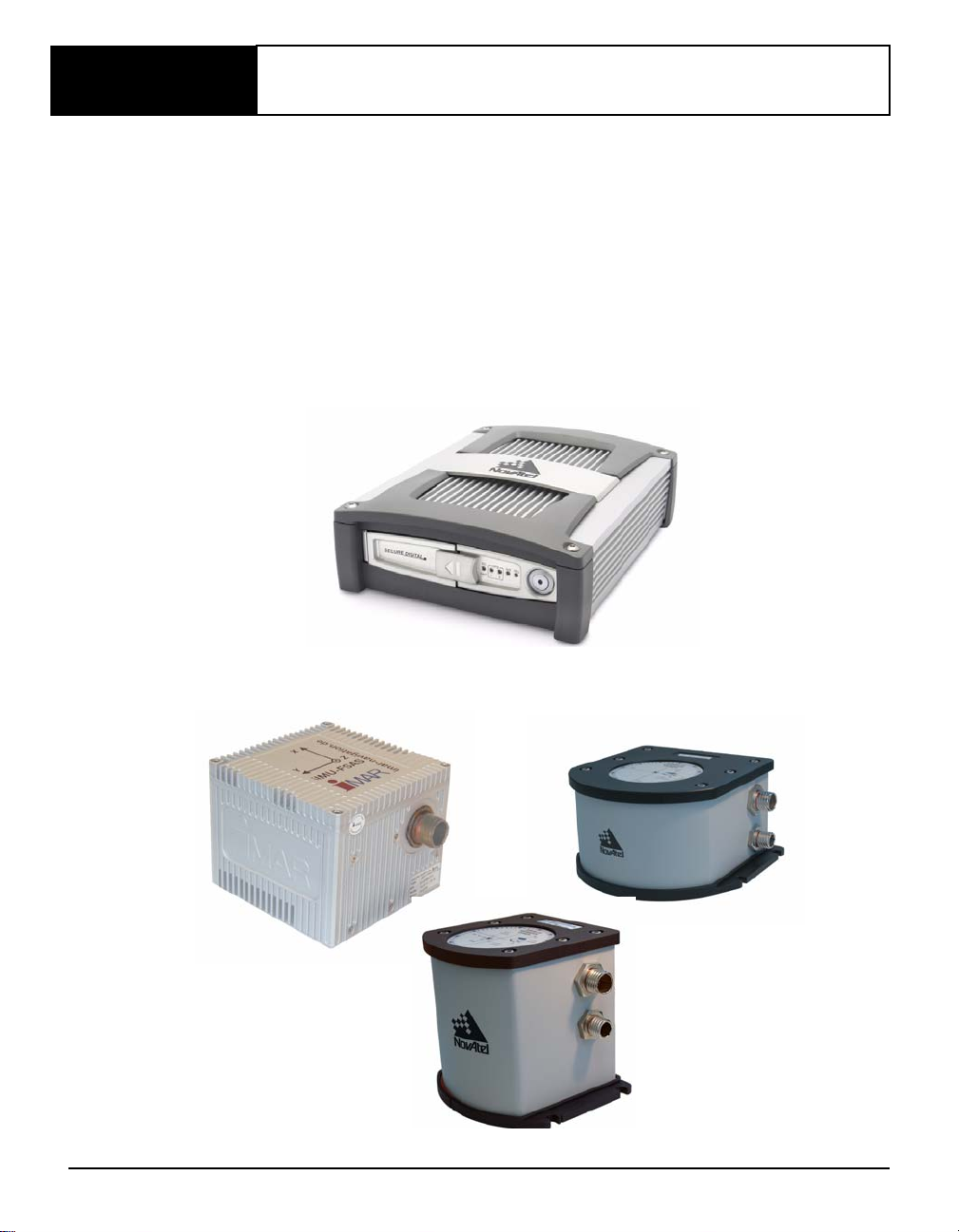
Figure 1: SPAN-SE Receiver
Figure 2: SPAN System IMUs
22 SPAN-SE User Manual Rev 1

Introduction Chapter 1
The SPAN system consists of the following components:
• A SPAN-capable receiver, such as SPAN-SE. The SPAN-SE is capable of receiving and
tracking different combinations of GPS, GLONASS, and L-band (CDGPS and OmniSTAR)
signals using a maximum of 72 channels. Patented Pulsed Aperture Correlator (PAC)
technology combined with a powerful microprocessor make possible multipath-resistant
processing. Excellent acquisition and re-acquisition times allow this receiver to operate in
environments where very high dynamics and frequent interruption of signals can be
expected. The receiver also supports the timing requirements of the IMU and runs the realtime INS Kalman filter.
The SPAN-SE also offers on-board data logging with a Secure Digital (SD) card, Ethernet
connectivity, wheel sensor input and scalability for future GNSS advances.
• IMU Enclosure - The Inertial Measurement Unit (IMU) is housed in the IMU enclosure that
provides a steady power supply to the IMU, and decodes and times the IMU output data. The
IMU itself consists of three accelerometers and 3 gyroscopes (gyros) so that accelerations
along specific axis and angular rotations can be measured. Several IMU types are supported
and are listed in Table 1, SPAN-SE Compatible Receiver and IMU Models on Page 24 and
Table 30, IMU Type on Page 138.
• PC Software - Real-time data collection, status monitoring and receiver configuration is
possible through NovAtel’s Control and Display Unit (CDU) software utility, see Section 3.2
on Page 36.
• A dual-frequency GNSS or GNSS/GLONASS Antenna.
The GNSS receiver is connected to the IMU enclosure with an RS-232 or RS-422 serial link. A
NovAtel GNSS antenna must also be connected to the receiver to track GNSS signals. Once the IMU
enclosure, GNSS antenna and appropriate power supplies are attached, and a few simple configuration
commands are entered, the SPAN system will be up and running and ready to navigate.
1.1 Fundamentals of GNSS/INS
GNSS positioning observes range measurements from orbiting Global Positioning System and
GLONASS satellites. From these observations, the receiver can compute position and velocity with
high accuracy. NovAtel GNSS positioning systems have been established as highly accurate
positioning tools; however GNSS in general has some significant restrictions, which limit its
usefulness in some situations. GNSS positioning requires line of site view to at least four satellites
simultaneously. If these criteria are met, differential GNSS positioning can be accurate to within a few
centimeters. If however, some or all of the satellite signals are blocked, the accuracy of the position
reported by GNSS degrades substantially, or may not be available at all.
In general, an inertial navigation system (INS) uses forces and rotations measured by an IMU to
calculate position, velocity and attitude. This capability is embedded in the firmware of SPAN capable
receivers. Forces are measured by accelerometers in three perpendicular axes within the IMU and the
gyros measure angular rotation rates around those axes. Over short periods of time, inertial navigation
gives very accurate position, velocity and attitude output. The INS must have prior knowledge of its
initial position, initial velocity, initial attitude, Earth rotation rate and gravity field. Since the IMU
measures changes in orientation and acceleration, the INS determines changes in position and attitude,
but initial values for these parameters must be provided from an external source. Once these
SPAN-SE User Manual Rev 1 23

Chapter 1 Introduction
parameters are known, an INS is capable of providing an autonomous solution with no external
inputs. However, because of errors in the IMU measurements that accumulate over time, an inertialonly solution degrades with time unless external updates such as position, velocity or attitude are
supplied.
The SPAN system’s combined GNSS/INS solution integrates the raw inertial measurements with all
available GNSS information to provide the optimum solution possible in any situation. By using the
high accuracy GNSS solution, the IMU errors can be modeled and mitigated. Conversely, the
continuity and relative accuracy of the INS solution enables faster GNSS signal reacquisition and
RTK solution convergence.
The advantages of using SPAN technology are its ability to:
• Provide a full attitude solution (roll, pitch and azimuth)
• Provide continuous solution output (in situations when a GNSS-only solution is impossible)
• Provide faster signal reacquisition and RTK solution resolution (over stand-alone GNSS
because of the tightly integrated GNSS and INS filters)
• Output high-rate (up to 100 or 200 Hz depending on your IMU model and other logging
selections) position, velocity and attitude solutions for high-dynamic applications
• Use raw phase observation data (to constrain INS solution drift even when too few satellites
are available for a full GNSS solution)
1.2 Models and Features
All SPAN system receivers are factory configurable for L1/L2 RTK capability and are compatible
with an IMU. See Table 1 for firmware model details.
Table 1: SPAN-SE Compatible Receiver and IMU Models
Model Name Max. Output Rate Compatible IMUs SPAN-SE Models
IMU-H58
IMU-H62
IMU-LN200 200 Hz LN-200
IMU-FSAS-EI 200 Hz iIMU-FSAS SPAN-SE-RT2-G-S-J
100 Hz HG1700-AG58
HG1700-AG62
200 and 400 Hz models
SPAN-SE-RT2-G-S-I
SPAN-SE-RT2-S-I
SPAN-SE-RT2-G-S-J
SPAN-SE-RT2-S-J
SPAN-SE-RT2-S-J
Each model is capable of multiple positioning modes of operation. For a discussion on GNSS
positioning, please refer to the OEMV Family Installation and Operation User Manual.
24 SPAN-SE User Manual Rev 1

Introduction Chapter 1
Each model has the following standard features:
• Rugged shock, water, and dust-resistant enclosure
• NovAtel's advanced OEMV L1/L2 GNSS/GLONASS and PAC technology
• Four bi-directional COM ports which support data transfer rates of up to 921,600 bits/s
1
• A removable SD Card slot for on-board data collection
• A USB port for PC communication
• A serial port capable of communication with an IMU. See also Ta ble 1 on page 24.
• An Ethernet port for TCP (or UDP) communication with the receiver
• Field-upgradeable firmware (program software).
2
What makes one model different from
another is software, not hardware. This unique feature means that the firmware can be
updated any time, anywhere, without any mechanical procedures whatsoever. For example, a
model with L1/L2-only capabilities can be upgraded to a model with L1/L2 RT-2 in only a
few minutes in your office (instead of the days or weeks that would be required if the
receiver had to be sent to a service depot). All that is required to unlock the additional
features is a special authorization code. Refer to the SPANAUTH command on Page 148 for
further details on this topic.
SPAN currently supports Honeywell, iMAR and Litton IMUs. When using an IMU with SPAN, it is
housed in an enclosure with a PCB board to handle power, communication and data timing. See
Appendix A, Technical Specifications starting on Page 61 for details.
1. Rates higher than 115, 200 are not standard on most PCs and may require extra PC hardware
2. You must have a valid Post Contractual Support (PCS) subscription, refer to our website at
www.novatel.com
.
SPAN-SE User Manual Rev 1 25

Chapter 2 SPAN-SE Installation
This chapter contains instructions to set up your SPAN-SE system.
SPAN-SE uses NovAtel’s powerful OEMV receiver technology as its GNSS engine. The OEMV
delivers many enabling features like GNSS/GLONASS capability and AdVance RTK, which are both
supported in SPAN-SE. A dedicated CPU, for real-time GNSS/INS processing on these cards, results
in fast data rates and low raw data and solution latency for highly dynamic or time-critical
applications.
2.1 SPAN-SE Hardware Description
The basic hardware setup consists of a SPAN-SE receiver (see Figure 1 on Page 22) connected to an
IMU (see Figure 2 on Page 22), a GNSS antenna and a power supply.
For real time differential operation, a communication link between the base and rover(s) is necessary.
This can be a null-modem cable or a radio link.
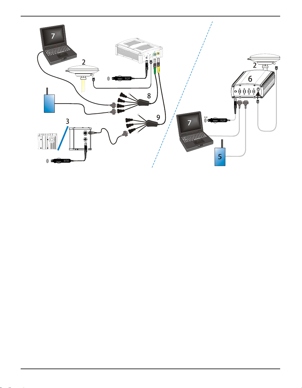
Figure 3 on Page 27 shows a basic setup plus a radio link on the base and the rover. Remove the
complete base side of the figure and the radio links from Figure 3 for a basic setup; see also Step 6’s
figure on Page 31.
Also, Figure 3 on Page 27 shows a setup with the LN-200 IMU and the iIMU as an option. For more
details on the connections between the SPAN-SE receiver and the iIMU, see Figure 25, iIMU
Interface Cable Connections with a SPAN-SE on Page 77.
If your IMU enclosure and IMU have come separately, additional installation instructions for
installing the IMU can be found in Appendix E, HG1700 IMU Installation starting on Page 277 or
Appendix F, LN-200 IMU Installation starting on Page 282.
For more information on SPAN-SE cables, please see Appendix A, Technical Specifications on Page
61.
26 SPAN-SE User Manual Rev 1
SPAN-SE Installation Chapter 2
4
1
12V
4
5
Base
Rover
12V
4
Reference Description
1 SPAN-SE receiver with an on-board SD Card for data storage
2 User-supplied NovAtel GNSS antenna
3 LN-200, HG-1700 or iIMU FSAS IMU and IMU interface cable to the
connector labelled IMU on the SPAN-SE I/O 2 yellow cable. For
the other connections, that only apply to the iIMU-FSAS, see
Section A.2.2.1, iIMU-FSAS Interface Cable starting on Page 77.
4 User-supplied power supply:
SPAN-SE rover (1): +9 to +28 V DC
ProPak-V3 base (6): +9 to +18 V DC
Separate supply for IMU (3): see Table 3 on Page 32
5 User-supplied radio device to the connector labelled OEMV3 on the
SPAN-SE I/O green cable.
6 User-supplied base station (ProPak-V3) receiver
7 User-supplied PC/laptop, for setting up and monitoring, to COM1 on
available COM ports, the USB host port or the Ethernet port
the ProPak-V3, or in the case of the SPAN-SE to one of the four
8 SPAN-SE I/O 1 green cable see Section A.1.1.2, I/O 1 Green Cable
(NovAtel part number 01018134) on Page 65
9 SPAN-SE I/O 2 yellow cable see Section A.1.1.3, I/O 2 Yellow
Cable (NovAtel part number 01018133) on Page 67
Figure 3: Basic SPAN-SE Set-Up
The sections that follow outline how to set up the system’s parts and cables. See the specifications
starting on Page 85 for the NovAtel part numbers of SPAN-SE cables and their pinouts.
SPAN-SE User Manual Rev 1 27
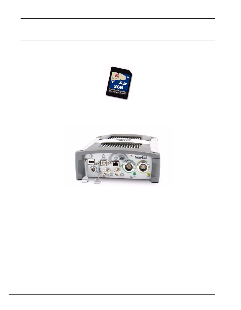
Chapter 2 SPAN-SE Installation
Data can be collected through any of the peripheral devices: USB, Ethernet, or serial COM ports.
Ensure that your peripheral is configured for a suitably high baud rate to handle the size of the
logs you request. USB is recommended for logging of high-rate data.
Data storage is via a Secure Digital (SD) memory card that you access in the front of the SPAN-SE.
See also Section 3.8, The SD Card starting on Page 53.
Figure 4: SD Memory Card
The back panel of the SPAN-SE is shown in Figure 5. The SPAN-SE has multiple COM and I/O
connectors. Note that there is more than one interface cable with the SPAN-SE.
Figure 5: Receiver Enclosure Back Panel
Table 2 on Page 29 shows a summary of the receiver’s back panel port names.
28 SPAN-SE User Manual Rev 1

SPAN-SE Installation Chapter 2
Table 2: Receiver Enclosure Back Panel Labels
SPAN Enclosure Port Label Description
SPAN-SE
Power
9-28 VDC
USB Host USB Host
USB Device USB Device
Ethernet Ethernet
GPS1 Antenna 1
GPS2 Antenna 2 (optional)
I/O 1
I/O 2
Supply Voltage
Green multi-pin connector 1
containing SPAN-SE COM ports,
OEMV COM port, event inputs,
and output strobes
Yellow multi-pin connector 2
containing SPAN-SE COM ports,
IMU COM port, event inputs, and
output strobes
Each connector can be inserted in only one way, to prevent damage to both the receiver and the cables.
Furthermore, the connectors that are used to mate the cables to the receiver require careful insertion
and removal. Observe the following when handling the cables.
• To insert a cable, make certain you are using the appropriate cable for the port - the
I/O cable has a different connector (number of pins) than the power cable
• Insert the connector until it is straight on and secure
• To remove a cable, grasp it by the connector and pull
WARNING: DO NOT PULL DIRECTLY ON THE CABLE.
Review this section’s hardware set-up subsections and follow the numbered steps, in bold, to install
your SPAN system. The example graphics, in the sections that follow, show the connections on the
back of a SPAN-SE receiver.
2.2 SPAN-SE Hardware Installation
2.2.1 Mount Antenna
For the best possible positioning precision and accuracy, as well as to minimize the risk of damage,
ensure that the antenna is securely mounted on a stable structure that will not sway or topple. Where
possible, select a location with a clear view of the sky to the horizon so that each satellite above the
horizon can be tracked without obstruction. The location should also be one that minimizes the effect
of multipath interference. For a discussion on multipath, please refer to the G NSS+ Reference Manual.
SPAN-SE User Manual Rev 1 29

Chapter 2 SPAN-SE Installation
2.2.2 Mount IMU
Mount the IMU in a fixed location where the distance from the IMU to the GNSS antenna phase
center is constant. Ensure that the orientation with respect to the vehicle and antenna is constant and
that the distance and relative direction between them is fixed.
The IMU should be mounted in such that the positive Z-axis marked on the enclosure points up and
the Y-axis points forward through the front of the vehicle, in the direction of track. The IMU can be
mounted in other orientations, see Section 29, Full Mapping Definitions on Page 135, but this can
make interpreting the raw IMU and attitude output more difficult.
Also, it is important to measure the distance from the IMU to the antenna (the Antenna Lever Arm),
on the first usage, on the axis defined on the IMU enclosure. See Section 3.4.6, Lever Arm Calibration
Routine starting on Page 47. See also Appendix A, T echnical Specifications starting on Page 61, which
gives dimensional drawings of the IMU enclosures.
1. The closer the antenna is to the IMU, the more accurate the position solution. Also, your
measurements when using the SETIMUTOANTOFFSET command must be as accurate
as possible, or at least more accurate than the GNSS positions being used. For example,
a 10 cm error in recording the antenna offset will result in at least a 10 cm error in
the output. Millimeter accuracy is preferred.
2. The offset from the IMU to the antenna, and/or a user point device, must remain constant
especially for RTK or DGPS data. Ensure the IMU, antenna and user point device are bolted
in one position perhaps by using a custom bracket.
2.2.3 Connect Interface Cables
The SPAN-SE has two circular connectors on the back panel. Each connector has a cable that breaks
out the serial ports into DB9 connectors and the input and output event signals to bare wires. Each
peripheral signal is identified on the cable with a label.
See Section A.2.3.3, Electrical and Environmental on Page 85 for more information on signals, wiring
and pin-out information of the SPAN-SE port and its cables.
1. Connect the I/O 1 green cable’s 30-pin connector to the I/O 1 green port on the SPAN-SE.
2. Connect the I/O 2 yellow cable’s 30-pin connector to the I/O 2 yellow port on the SPAN-SE.
3. Connect a communications cable.
If you want to connect via a serial connection, the I/O 1 green cable has a DB9 connectors for
COM3 and COM4 and the I/O 2 yellow cable has DB9 connections for COM1 and COM2.
If a USB connection is required, connect a USB cable to the USB Device port. USB Host support
is not available at this time.
If an Ethernet connection is required, connect a network cable to the Ethernet port.
30 SPAN-SE User Manual Rev 1
 Loading...