

Novatel SPAN CPT7 Quick Start Manual

1
SPAN CPT7™
GM-14915154 Rev 1A August 2018
QUICK START GUIDE
*GM-14915154*
The NovAtel® SPAN CPT7 is a compact, single enclosure GNSS+INS receiver. This guide provides the
basic information needed to set up and use a SPAN CPT7.
USER DOCUMENTATION
For detailed information on the installation, operation, logs and commands for the SPAN CPT7, refer to the
OEM7 User Documentation (docs.novatel.com/OEM7
).
BOX CONTENTS
The following is provided with the SPAN CPT7:
• SPAN CPT7 I/O1 Cable (60723180)
• SPAN CPT7 I/O2 Cable (60723181)
ADDITIONAL EQUIPMENT REQUIRED
The additional equipment listed below is required for a typical setup (refer to the OEM7 User
Documentation (docs.novatel.com/OEM7)
for further details).
• A 9-32 VDC, fuse protected power supply capable of at least 18 W
• Two high quality GNSS antennas, such as NovAtel’s VEXXIS
®
GNSS-500 or GNSS-800 series
antennas
• Two antenna cables with an SMA male connector at the SPAN CPT7 end
• Four #6 size screws for mounting.
• A computer with a serial COM, USB or Ethernet port
OPTIONAL ACCESSORIES
The following optional accessory is available from NovAtel:
• SPAN CPT7 Adapter Plate (70023109)
This plate mounts on the SPAN CPT7 and provides SPAN-CPT and SPAN-IGM compatible mounting
holes.
For information about this accessory, refer to the OEM7 User Documentation (docs.novatel.com/OEM7
).
2
GETTING TO KNOW THE SPAN CPT7
Refer to the OEM7 User Documentation (docs.novatel.com/OEM7) for details on SPAN CPT7 connectors
as well as detailed installation and operation instructions and information regarding SPAN CPT7 logs and
commands.
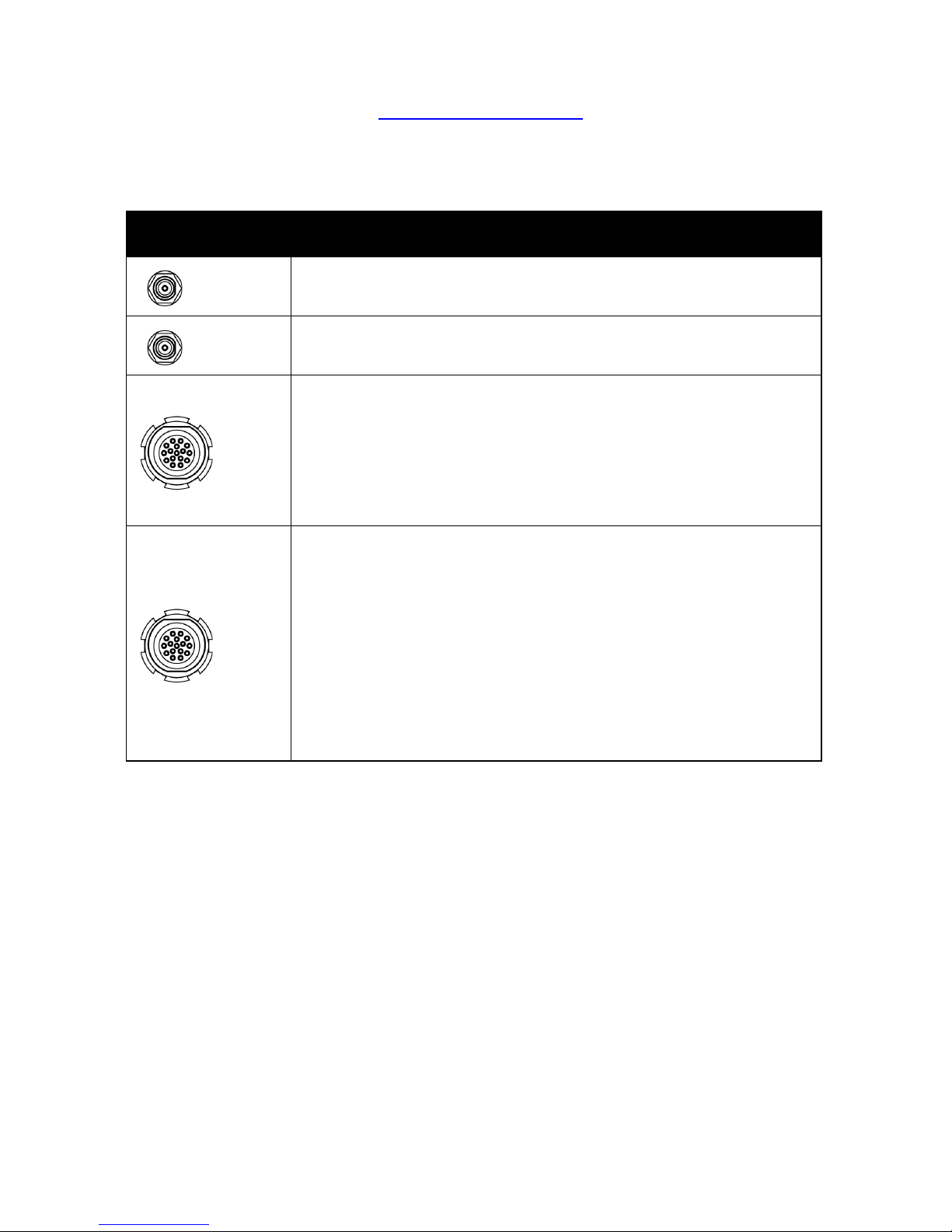
Table 1: SPAN CPT7 - Connector Definitions
Connector Description
RF1
SMA connector for the primary GNSS antenna
RF2
SMA connector for the secondary GNSS antenna
IO1
16-pin circular connector
• Power
• 7720-COM2 (RS-422)
• EVENT_IN 1
• EVENT_OUT 1
IO2
16-pin circular connector
• Power
• 7720-COM1 (RS-232)
•USB
• Ethernet
•CAN bus
• EVENT_IN 2
• EVENT_OUT 2
3
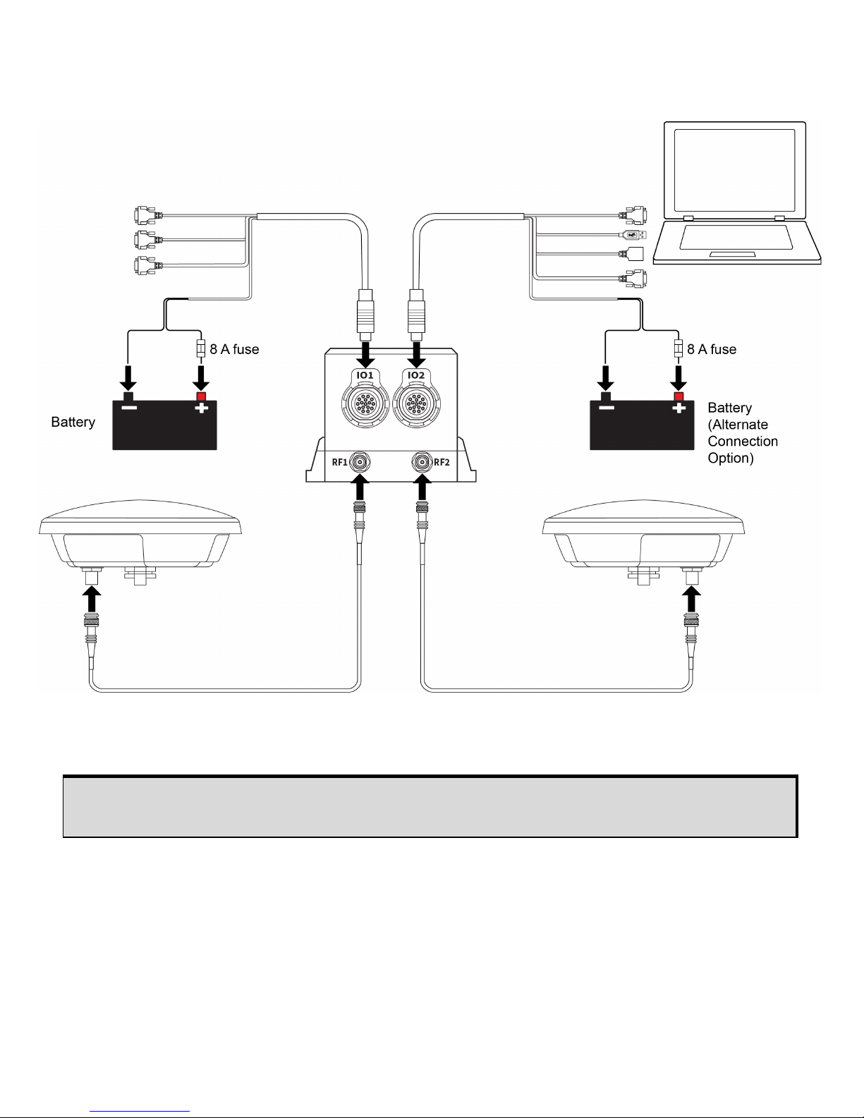
SETTING UP A SPAN CPT7
Complete the following steps to connect and power the SPAN CPT7.
1. Mount the SPAN CPT7. See SPAN CPT7 Mounting on page 5 for details.
2. Mount both GNSS antennas to a secure, stable structure with an unobstructed view of the sky.
3. Connect the primary GNSS antenna to the RF1 port and the secondary GNSS antenna to the RF2
port.
ALIGN heading accuracy is dependent on the antenna baseline length. For best results,
mount the GNSS antennas at least one metre apart.
 Loading...