

Novatel SMART7, SMART7-W, SMART7-I, SMART7-S Installation And Operation Manual

SMART7
Installation and Operation
User Manual
OM-20000181 0C October 2018

SMART7 Installation and Operation User Manual
Publication Number: OM-20000181
Revision Level: 0C
Revision Date: October 2018
Firmware Version: 7.05.01 / OA7CR0501RN0000
Warranty
NovAtel Inc. warrants that its GNSS products are free from defects in materials and workmanship, subject to the conditions set forth on our web site: www.nova-
tel.com/products/warranty/ and for the following time periods:
OEM7®Receivers One (1) Year
GNSS Antenna Series One (1) Year
Cables and Accessories Ninety (90) Days
Software Warranty One (1) Year
Return instructions
To return products, refer to the instructions found at: www.novatel.com/warranty-return.
Proprietary Notice
Information in this document is subject to change without notice and does not represent a commitment on the part of NovAtel Inc. The software described in this document is furnished under
a licence agreement or non-disclosure agreement. The software may be used or copied only in
accordance with the terms of the agreement. It is against the law to copy the software on any
medium except as specifically allowed in the license or non-disclosure agreement.
No part of this manual may be reproduced or transmitted in any form or by any means, electronic or mechanical, including photocopying and recording, for any purpose without the express
written permission of a duly authorized representative of NovAtel Inc.
The information contained within this manual is believed to be true and correct at the time of
publication.
NovAtel, ALIGN, GLIDE, GrafNav/GrafNet, Inertial Explorer, NovAtel CORRECT, OEM7, PwrPak7,
RELAY, SPAN, STEADYLINE, VEXXIS and Waypoint are registered trademarks of NovAtel Inc.
NovAtel Connect, OEM719, OEM729, OEM7500, OEM7600, OEM7700, OEM7720, SMART7 and RTK
ASSIST are trademarks of NovAtel Inc.
All other brand names are trademarks of their respective holders.
© Copyright 2018 NovAtel Inc. All rights reserved. Unpublished rights reserved under International copyright laws.
SMART7 Installation and Operation User Manual 0C 2

Table of Contents
Figures
Tables
SMART7 Notices
Customer Support
Chapter 1 SMART7 Overview
1.1 Features and Models 16
1.2 SMART7 Connectors Overview 17
1.3 SMART7 LEDs 18
1.4 Related Documents and Information 20
1.5 SMART7 Emulated Radar 20
1.5.1 Emulated Radar (ER) 20
Chapter 2 SMART7 Installation Overview
2.1 Power Supply Requirements for the SMART7 22
2.2 Mounting and Orienting the SMART7 22
2.2.1 Mounting 22
2.2.2 Orienting 23
2.2.3 SMART7 and SMART6 Mounting Hole Locations 23
2.3 Connect the SMART7 to Data Communication Equipment 24
2.3.1 Serial Ports 24
2.3.2 Wi-Fi 25
2.3.3 Ethernet Port 25
2.3.4 CAN Bus Port 26
2.4 Connect I/OSignals to the SMART7 26
2.5 Connect Power to the SMART7 26
2.5.1 Fuse for the Power Supply 26
2.6 Check that the SMART7 is Working 27
2.7 SMART7 Additional Equipment Required 28
SMART7 Operation
3.1 Communications with the Receiver 30
3.1.1 Serial Port Communications 30
3.1.2 Ethernet Communications 32
3.1.3 ICOM Communications 32
3.1.4 CAN Bus Communications 33
3.2 Getting Started 33
3.2.1 Communicating with the Receiver 33
3.3 Transmitting and Receiving Corrections 34
3.3.1 Defining Antenna and Base Antenna 36
3.3.2 Base Station Configuration 36
3.3.3 Rover Station Configuration 37
3.3.4 Configuration Notes 37
3.4 ALIGN Heading Master and Remote Configurations 38
3.4.1 Automatic Set Up for Direct-Wire Connection between Master and Rover via
COM2 38
3.4.2 Manual Set Up via COM2 39
3.5 GLIDE 39
SMART7 Installation and Operation User Manual 0C 3

3.5.1 Dual-Frequency GLIDE 39
3.5.2 PDP and GLIDE Configurations 40
3.6 STEADYLINE 40
3.6.1 Maintain 41
3.6.2 Transition 41
3.6.3 Prefer Accuracy 41
3.6.4 UAL 42
3.7 Enabling SBAS Positioning 43
3.8 Enabling NovAtel CORRECT with PPP 43
3.8.1 TerraStar Subscriptions 44
3.8.2 Veripos Subscriptions 45
3.9 RTK ASSIST 45
3.10 Logging Using NovAtel Connect 46
3.10.1 Selecting the Logs to Collect 47
3.10.2 Modify the Logging Parameters 47
3.10.3 Start Collecting Logs 48
3.10.4 Stop Collecting Logs 48
3.10.5 Change the Log File Settings 48
SMART7 with SPAN Operation
4.1 Fundamentals of GNSS+INS 50
4.2 Definition of Reference Frames Within SPAN 51
4.2.1 The Local-Level Frame (ENU) 51
4.2.2 The IMU Body Frame 52
4.2.3 The Vehicle Frame 52
4.2.4 The User Output Frame 53
4.3 SPAN Translations and Rotations 53
4.3.1 Translational Offsets 54
4.3.2 Rotational Offsets 56
4.3.3 Importance of RBV Calibration 61
4.4 Software Configuration 62
4.4.1 Minimum Recommended Configuration 62
4.4.2 GNSS Configuration 63
4.4.3 SPAN Configuration 63
4.5 Real-Time Operation 64
4.5.1 System Start-Up and Alignment Techniques 66
4.5.2 INSSeed / Fast INS Initialization 67
4.5.3 Navigation Mode 70
4.5.4 Data Collection 70
4.5.5 Body to Vehicle Frame Rotation Calibration Routine 71
4.5.6 Multi-Line Body to Vehicle Frame Rotation Calibration Routine 72
4.6 Azimuth Sources on a SPAN System 74
4.6.1 Course Over Ground 74
4.6.2 Inertial Azimuth 75
4.6.3 ALIGN Azimuth 75
4.7 Data Collection for Post Processing 76
Chapter 5 Built-In Status Tests
5.1 RXSTATUSEVENT Log 77
5.2 RXSTATUS Log 77
5.2.1 Status Word 77
5.2.2 Error Word 78
5.2.3 Status Code Arrays 79
5.2.4 Receiver Status Code 79
SMART7 Installation and Operation User Manual 0C 4

5.2.5 Auxiliary Status Codes 79
5.2.6 Set and Clear Mask for all Status Code Arrays 80
SMART7-I and SMART7-W Wi-Fi Configuration Overview
5.3 Wi-Fi Modes 81
5.3.1 Access Point (AP) 81
5.3.2 Client 81
5.3.3 Concurrent 81
5.4 SMART7-I and SMART7-W Wi-Fi Modes 82
5.4.1 Enable the Wi-Fi Access Point 82
5.4.2 Enable the Wi-Fi Client 83
5.4.3 Enable the Wi-Fi Concurrent 84
5.5 SMART7-I and SMART7-W Wi-Fi Changes 85
5.5.1 Change the Wi-Fi Passkey 85
5.5.2 Change the SSID 86
5.5.3 Change the Wi-Fi Channel 86
5.5.4 Change the Wi-Fi IPAddress 86
5.5.5 Disable Wi-Fi 86
5.6 SMART7-I and SMART7-W ALIGN Over Wi-Fi Overview 87
5.6.1 SMART7-I and SMART7-W Automatic Wi-Fi ALIGN Corrections 87
5.6.2 SMART7-I and SMART7-W Manual Set Up for Wi-Fi Connection between Master
and Rover via ICOM1 88
Chapter 6 Ethernet Configuration
6.1 Required Hardware 91
6.2 Static IP Address Configuration 91
6.2.1 Static IP Address Configuration—Receiver 92
6.2.2 Static IP Address Configuration—Windows 7 93
6.2.3 Confirming Ethernet Setup 93
6.3 Dynamic IP Address Configuration 94
6.4 Base/Rover Configuration through Ethernet Connectivity 94
6.5 Large Ethernet Port Data Throughput 96
6.6 NTRIP Configuration 96
Chapter 7 CAN Bus
7.1 Default Configuration 100
7.2 Configuring the CAN Bus 100
7.2.1 Configuration Notes 100
7.2.2 Example of Enabling the CAN Bus 101
7.2.3 Example of Modifying the CAN Bus Parameters 101
7.2.4 Example of Detecting an Address Claim Failure and Reconfiguring 101
7.2.5 Address Claim Procedure 102
7.3 NMEA2000 Logging 102
7.3.1 Example of NMEA2000 Log Configuration 103
7.3.2 Example of Custom PGN Configuration 103
7.4 Corrections Over CAN 103
7.4.1 Example for Receiving Corrections from Any Source 104
7.4.2 Example for Transmitting Corrections to 0x1C Node 104
7.5 NovAtel Messages Over CAN 104
7.6 Configuring OEM7 Receivers to Use OEM6 CAN Settings 104
7.6.1 Configuration on OEM6 105
7.6.2 Configuration on OEM7 105
SMART7 Installation and Operation User Manual 0C 5

Chapter 8 Troubleshooting
8.1 Examining the RXSTATUS Log 107
8.2 Examining the AUX1 Status Word 110
8.3 High Temperature Environments 111
8.3.1 Indicators of an Error State 111
8.3.2 Recovering from a Temperature Status Error 112
8.3.3 Mitigating High Receiver Temperature 112
8.3.4 Monitoring the Receiver Temperature 112
8.4 Safe Mode 113
8.4.1 Reset Loop Detection 113
8.4.2 Recovery Steps 113
Chapter 9 NovAtel Firmware and Software
9.1 Firmware Updates and Model Upgrades 115
9.1.1 Firmware Updates 115
9.1.2 Model Upgrades 115
9.2 Authorization Code 116
9.3 Updating or Upgrading Using the WinLoad Utility 117
9.3.1 Transferring Firmware Files 117
9.3.2 Using the WinLoad Utility 117
9.4 Updating Using SoftLoad Commands 119
9.4.1 SoftLoad Commands and Logs 119
9.4.2 Working With S-Records 120
9.4.3 Sending Firmware Data 121
9.4.4 SoftLoad Update Method 122
9.4.5 SoftLoad Errors 125
9.5 Upgrading Using the AUTH Command 125
9.5.1 Upgrade Procedure 125
APPENDIX A SMART7 Technical Specifications
A.1 SMART7 Performance Specifications 128
A.2 SMART7 Mechanical Specifications 131
A.3 SMART7 Environmental and Electrical Specifications 133
A.4 SMART7 Data Communication Specifications 134
A.5 SMART7 Strobe Specifications 134
A.6 SMART7 Interface Cable (Optional Accessory) 136
A.0.1 SMART7 Custom Cable Recommendation 137
A.7 SMART7 Mounting Plate Specifications 138
APPENDIX B SMART7 Accessories and Replacement Parts
SMART7 Installation and Operation User Manual 0C 6

Figures
Figures
Figure 1: SMART7 with Ethernet Model (Back) 17
Figure 2: SMART7 Interface Connector 17
Figure 3: SMART7 Ethernet Connector (model dependent) 17
Figure 4: SMART7 LEDs Location 18
Figure 5: SMART7 Installation 21
Figure 6: SMART7 Magnetic Mounting Plate 23
Figure 7: SMART7 Orientation 23
Figure 8: SMART7 and SMART6 Mounting Hole Locations 24
Figure 9: Basic Differential Setup 35
Figure 10: Positioning Change Without STEADYLINE 40
Figure 11: STEADYLINE Maintain 41
Figure 12: STEADYLINE Transition 41
Figure 13: STEADYLINE Prefer Accuracy 42
Figure 14: STEADYLINE UAL- Warning Limit Example 42
Figure 15: STEADYLINE UAL - Out of Bounds Example 43
Figure 16: Local-Level Frame (ENU) 52
Figure 17: Vehicle Frame 53
Figure 18: ALIGN Translation Offset 55
Figure 19: SMART7-S IMU Body Frame 57
Figure 20: SMART7-S IMU Body Frame with Factory Configured Rotation 58
Figure 21: SMART7-S Installed with Orientation Not Aligned with Vehicle Frame 59
Figure 22: Rear view of SMART7 on a Vehicle – Roof Camber 61
Figure 23: Side View of SMART7 on a Vehicle – Roof Tilt 61
Figure 24: Top View of SMART7 on a Vehicle – SMART7 Misalignment 62
Figure 25: Multi-Line IMU Body to Vehicle Calibration 73
Figure 26: Location of Receiver Status Word 77
Figure 27: Reading the Bits in the Receiver Status Word 78
Figure 28: Location of Receiver Error Word 78
Figure 29: Reading the Bits in the Receiver Error Word 78
Figure 30: Status Code Arrays 79
Figure 31: Cross-Over Ethernet Cable Configuration—OEM7 Receiver 92
Figure 32: Dynamic IP Address Configuration through a DHCP Server—OEM7 Receiver 94
Figure 33: Base/Rover Ethernet Setup—OEM7 Receiver 95
Figure 34: NTRIP System 97
Figure 35: WinLoad’s Open Window 118
Figure 36: Open File in WinLoad 118
Figure 37: COM Port Setup 119
Figure 38: SMART7 Dimensions 131
Figure 39: SMART7-S Center of Navigation 132
SMART7 Installation and Operation User Manual 0C 7

Figures
Figure 40: SMART7 Interface Cable 136
Figure 41: SMART7 Mounting Plate Dimensions (Optional) 138
SMART7 Installation and Operation User Manual 0C 8

Tables
Tables
Table 1: Model Variants 16
Table 2: Ethernet Connector Pin Outs 17
Table 3: SMART7 Status Indicators 18
Table 4: Wi-Fi LED 18
Table 5: Ethernet LED 19
Table 6: Status LED 19
Table 7: SMART7 Serial Port Protocol 24
Table 8: SMART7 Recommended Fuse and Fuse Holders 28
Table 9: Serial Ports Supported 31
Table 10: Inertial Solution Status 65
Table 11: NVM Seed Indication 69
Table 12: Solution Parameters 70
Table 13: Logs with Azimuth Data 75
Table 14: Wi-Fi Default Configuration 82
Table 15: Default NAME 100
Table 16: Troubleshooting Based on Symptoms 106
Table 17: Resolving a Receiver Error Word 108
Table 18: Resolving an Error in the Receiver Status Word 109
Table 19: Resolving an Error in the AUX1 Status Word 110
Table 20: SMART7 Physical Description 127
Table 21: SMART7 Receiver Performance 128
Table 22: SMART7-S IMU Performance 130
Table 23: SMART7 Environmental Specifications 133
Table 24: SMART7 Power Requirements 133
Table 25: Data Communications Interfaces 134
Table 26: SMART7 Strobes Description 135
Table 27: SMART7 Connector Pin Out 136
Table 28: 14-Pin Interface Connector 137
Table 29: I/O Connector 137
Table 30: SMART7 Products 139
SMART7 Installation and Operation User Manual 0C 9
SMART7 Notices
SMART7 Notices
The following notices apply to the SMART7 device.
Changes or modifications to this equipment, not expressly approved by NovAtel Inc.,
could void the user’s authority to operate this equipment.
FCC
This device complies with part 15 of the FCC Rules. Operation is subject to the following two conditions: (1) this device may not cause harmful interference, and (2) this device must accept any
interference received, including interference that may cause undesired operation.
SMART7 has been tested and found to comply with the radiated and conducted emission limits
for a Class B digital device. The Class B limits are designed to provide reasonable protection
against harmful interference in a residential installation.
The equipment listed generates, uses and can radiate radio frequency energy and, if not
installed and used in accordance with the instructions, may cause harmful interference to radio
communications. However, there is no guarantee that interference will not occur in a particular
installation. If this equipment does cause harmful interference to radio or television reception,
which can be determined by turning the equipment off and on, the user is encouraged to try to
correct the interference by one or more of the following measures:
l Re-orient or relocate the SMART7
l Increase the separation between the equipment and the SMART7
l Connect the equipment to an outlet on a circuit different from that to which the SMART7 is
connected
l Consult the dealer or an experienced radio/TV technician for help
The SMART7 has been authorized for use in Mobile applications. At least 20 cm (8
inches) of separation between the SMART7 and the User must be maintained at all
times.
Wi-Fi
SMART7 contains a Wi-Fi radio with the following approvals:
l FCC ID: UTU-01019715
Innovation, Science and Economic Development (ISED) Canada
SMART7 Class B digital device complies with Canadian ICES-003.
SMART7 appareil numérique de la classe B est conforme à la norme NMB-003 du Canada.
This device complies with ISED license-exempt RSS-GEN and RSS-247. Operation is subject to
the following two conditions: (1) this device may not cause interference and (2) this device must
accept any interference, including interference that may cause undesired operation of the
device.
Cet appareil est conforme à la norme ISED RSS-GEN et RSS-247. Son fonctionnement est soumis aux deux conditions suivantes: (1) cet appareil ne doit pas provoquer d'interférences et (2)
SMART7 Installation and Operation User Manual 0C 10
SMART7 Notices
cet appareil doit accepter toute interférence, y compris les interférences pouvant entraîner un
fonctionnement indésirable de l'appareil.
The SMART7 has been authorized for use in Mobile applications. At least 20 cm (8
inches) of separation between the SMART7 and the User must be maintained at all
times.
Le SMART7 a été autorisé pour une utilisation dans les applications mobiles. Au
moins 20 cm (8 pouces) de séparation entre le SMART7 et l'utilisateur doit être
maintenue à tous fois.
Wi-Fi
SMART7 contains a Wi-Fi radio with the following approvals:
l IC: 129A-01019715
European Union (EU)
SMART7 Wi-Fi
NovAtel Inc. declares that the SMART7 Wi-Fi transceiver is in compliance with Directive
2014/53/EU (Radio Equipment).
The full text of the EU Declaration of Conformity may be obtained from the NovAtel web site at:
www.novatel.com/products/compliance/eu-declaration-of-conformity
Radio Information
Description of Service: Wi-Fi (802.11b/g/n)
Operational Frequency: 2400 MHz to 2480 MHz
Modulation: OFDM
Rated Power: 13.4 dBm e.i.r.p
The full text of the EU Declaration of Conformity may be obtained from the NovAtel web site at:
www.novatel.com/products/compliance/eu-declaration-of-conformity
Japan
Wi-Fi
SMART7 contains a Wi-Fi radio with the following approvals:
Korea
Wi-Fi
SMART7 contains a Wi-Fi radio with the following approvals:
SMART7 Installation and Operation User Manual 0C 11
SMART7 Notices
Ethernet Port
The Ethernet port is a safety extra-low voltage (SELV) circuit only and is suitable for connection to another SELV circuit. Do not connect to Telecommunications Network Voltage
(TNV) circuits.
WEEE Notice
If you purchased your SMART7 product in Europe, please return it to your dealer or supplier at
the end of its life. The objectives of the European Community's environment policy are, in particular, to preserve, protect and improve the quality of the environment, protect human health
and utilise natural resources prudently and rationally. Sustainable development advocates the
reduction of wasteful consumption of natural resources and the prevention of pollution. Waste
electrical and electronic equipment (WEEE) is a regulated area. Where the generation of waste
cannot be avoided, it should be reused or recovered for its material or energy. WEEE products
may be recognized by their wheeled bin label ( ).
See www.novatel.com/products/compliance/environmental-compliance for more information.
RoHS
The SMART7 is in conformity with Directive 2011/65/EU of the European Parliament and of the
council of 8 June 2011 on the restriction of the use of certain hazardous substances in electrical
and electronic equipment.
REACH
The SMART7 is compliant with Regulation (EC) No. 1907/2006 of the European Parliament and
the Council of 18 December 2006 concerning the Registration, Evaluation, Authorization and
Restriction of Chemicals (REACH). The candidate list of Substances of Very High Concern (SVHC)
published by the European Chemical Agency (ECHA) is available at: https://echa.europa.eu-
/candidate-list-table
Conventions
The following conventions are used in this manual:
Information that supplements or clarifies text.
A caution that actions, operation or configuration may lead to incorrect or improper use
of the hardware.
SMART7 Installation and Operation User Manual 0C 12

SMART7 Notices
A warning that actions, operation or configuration may result in regulatory noncompliance, safety issues or equipment damage.
SMART7 Installation and Operation User Manual 0C 13
Customer Support
Customer Support
NovAtel Knowledge Base
If you have a technical issue, visit the NovAtel Support page at www.novatel.com/support.
Through the Support page, you can contact Customer Support, find papers and tutorials or download current manuals and the latest firmware.
Before Contacting Customer Support
Before you contact NovAtel Customer Support about a software problem, perform the following
steps:
If logging data over an RS-232 serial cable, ensure that the configured baud rate can support the data bandwidth (see SERIALCONFIG command). NovAtel recommends a min-
imum suggested baud rate of 230400 bps.
1.
Log the following data to a file on your computer for 15 minutes:
RXSTATUSB onchanged
RAWEPHEMB onchanged
GLORAWEPHEMB onchanged
BESTPOSB ontime 1
RANGEB ontime 1
RXCONFIGA once
VERSIONA once
For SPAN systems, add the following logs to the above list in the file created on your computer:
RAWIMUSXB onnew
INSUPDATESTATUSB onnew
INSPVAXB ontime 1
INSCONFIGA once
2.
Send the data file to NovAtel Customer Support: support@novatel.com
3.
You can also issue a FRESET command to the receiver to clear any unknown settings.
The FRESET command will erase all user settings. You should know your configuration
(by requesting the RXCONFIGA log) and be able to reconfigure the receiver before you
send the FRESET command.
If you are having a hardware problem, send a list of the troubleshooting steps taken and the results.
Contact Information
Log a support request with NovAtel Customer Support using one of the following methods:
Log a Case and Search Knowledge:
SMART7 Installation and Operation User Manual 0C 14

Customer Support
Website: www.novatel.com/support
Log a Case, Search Knowledge and View Your Case History: (login access required)
Web Portal: https://novatelsupport.force.com/community/login
E-mail:
support@novatel.com
Telephone:
U.S. and Canada:1-800-NOVATEL (1-800-668-2835)
International:+1-403-295-4900
SMART7 Installation and Operation User Manual 0C 15

Chapter 1 SMART7 Overview
The SMART7 is a high performance GNSS receiver and antenna, capable of receiving and tracking all current GNSS signals on a maximum of 555 channels. Support for SBAS (Satellite Based
Augmentation Systems) is standard and includes WAAS (North America), EGNOS (Europe) and
MSAS (Japan). Refer to An Introduction to GNSS (on our website at www.novatel.com/an-intro-
duction-to-gnss) for an overview of each of the above signal types. The SMART7 features Light
Emitting Diodes (LEDs) for status indication.
Once properly powered, the SMART7 begins operating as a fully functional GNSS system.
1.1 Features and Models
The main features of the SMART7 are:
l
an enhanced high performance multi-frequency, multi-constellation receiver
l
a high performance GNSS multi-frequency, multi-constellation antenna
l
a CAN port
l
Emulated Radar Output
three (3) RS-232 COM ports
l
up to three (3) LED status indicators (model dependent)
l
a water and dust tight enclosure
l
enhanced interference mitigation
The SMART7 is available in several different hardware configuration and firmware models
whose additional features may include:
l
Wi-Fi interface
l
Ethernet port
l
Integrated SPAN GNSS+INS functionality
l
Web UI
Contact NovAtel Sales at www.novatel.com/where-to-buy/contact-us for information regarding
available models, upgrading a model to increase feature/functionality or go to
https://www.novatel.com/products/smart-antennas/smart7-products. Refer to Firmware
Updates and Model Upgrades on page115 for details.
Table 1: Model Variants
Product Hardware Model Model
SMART7 SMART7
SMART7 with Wi-Fi and Ethernet SMART7-I
SMART7 with Wi-Fi SMART7-W
SMART7 with SPANIMU SMART7-S
SMART7 Installation and Operation User Manual 0C 16
Chapter 1 SMART7 Overview
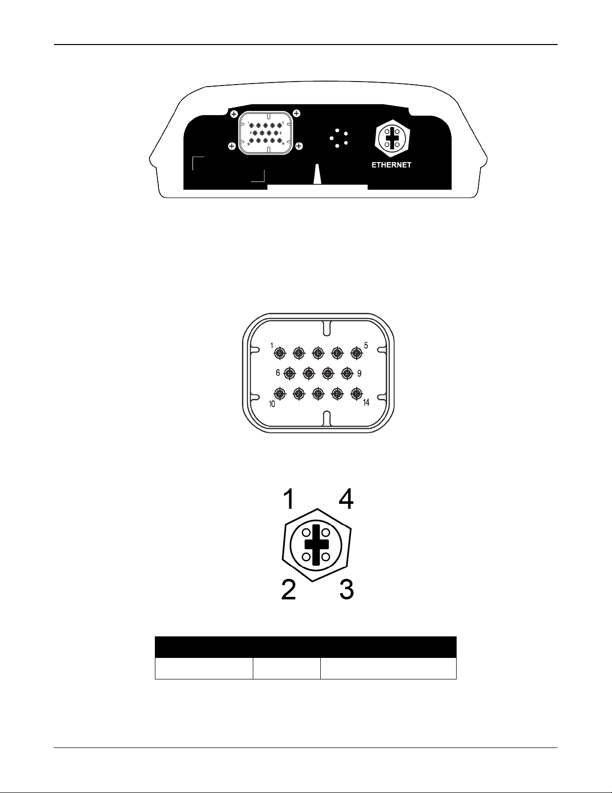
Figure 1: SMART7 with Ethernet Model (Back)
1.2 SMART7 Connectors Overview
All SMART7 models use the same connector for power and communication. Refer to Table 27:
SMART7 Connector Pin Out on page136 for pin outs.
Figure 2: SMART7 Interface Connector
The SMART7 Ethernet model has a M12 D-code male connector.
Figure 3: SMART7 Ethernet Connector (model dependent)
Table 2: Ethernet Connector Pin Outs
From P1 To J1 Signal Name
1 1 Tx+
SMART7 Installation and Operation User Manual 0C 17
Chapter 1 SMART7 Overview
From P1 To J1 Signal Name
2 2 Rx+
3 3 Tx-
4 4 Rx-
Shell Shell Chassis GND
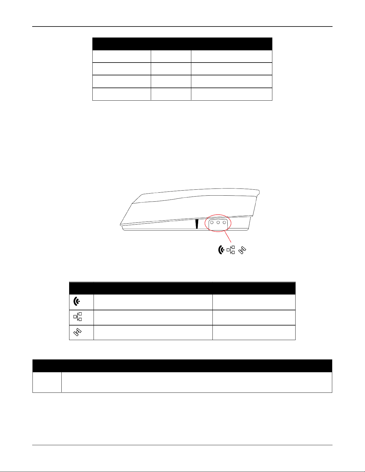
1.3 SMART7 LEDs
The SMART7 has up to three LEDs (model dependent) to indicate receiver status.
The following tables provide information about the SMART7 LEDs and their states.
Figure 4: SMART7 LEDs Location
Table 3: SMART7 Status Indicators
Label Description Variants
Wi-Fi mode (AP, Concurrent or Client) SMART7-I and SMART7-W
Ethernet (DATA) SMART7-I
Status (Power/GNSS) All variants
Table 4: Wi-Fi LED
State Description
Green
Solid
Configured as anAccess Point (default)
SMART7 Installation and Operation User Manual 0C 18
Chapter 1 SMART7 Overview
State Description
Green
Slow
Configured as an Access Point with at least one client connection
Flash
Blue
Solid
Blue
Slow
Flash
White
Solid
While
Slow
Flash
Yellow
Slow
Flash
Red
Solid
Red
Fast
Flash
Configured as both an Access Point and a Client concurrently
Configured as both an Access Point and a Client concurrently, with at least one Client
connected to the concurrent Access point or with the concurrent Client connected to an
Access Point
Configured as a Client
Configured as a Client and connected to an Access Point
Wi-Fi Firmware Upgrade
No Configuration
Error State
Table 5: Ethernet LED
State Description
Green Solid Link established
Green Slow Flash Active (receiving or transmitting)
Table 6: Status LED
State Description
Green Solid RTK/PPP Solution good or RTK/PPP/INS Solution good
Green Slow Flash PPPor RTKConverging
Yellow Solid WAAS/Single Point
SMART7 Installation and Operation User Manual 0C 19
Chapter 1 SMART7 Overview
State Description
Yellow Slow Flash (1 Hz) Tracking at least one satellite but no valid position
Yellow Fast Flash (3 Hz) Initialized and ready for communication
Red Solid Power On/Error/Reset
Red Slow Flash (1 Hz) Position Error
Red Fash Flash (3 Hz) Solution Error
1.4 Related Documents and Information
After the OEM7 receiver is set up,the Agriculture Commands and Logs Reference Manual
becomes the primary source for command and log information.
Each receiver has a specific set of features, so some commands and logs may not be supported by your model.
Refer to our web site docs.novatel.com/OEM7 for the latest documentation.
This manual does not cover OEM7 service and repair. Contact a local NovAtel dealer for service
or repair inquiries (refer to Customer Support on page14 for contact details).
1.5 SMART7 Emulated Radar
1.5.1 Emulated Radar (ER)
A typical radar sensor emits radio beams that bounce off the ground and computes ground speed
based on the speed at which objects are passing in front of the sensor. The output of the sensor
is a digital pulse, the frequency of which is proportional to the vehicle’s ground speed. This is
often used in agricultural applications such as planting and spraying. The SMART7 eliminates the
need for separate ground-sensing radar equipment by converting the GPS-derived velocity to
proportional frequency output. The following emulated radar signal parameters can be configured by the customer:
l
Frequency Step: Specifies how the frequency output relates to the vehicle speed.
l
Signal Update Rate: Specifies how often the frequency output is updated to match the
vehicle speed.
l
Response Mode: Specifies how quickly changes in velocity are reflected in the frequency output. Setting a slower response mode reduces spikes (noise) in the velocity but increases
latency. Setting a higher response mode reduces latency, but may result in noisier frequency
output.
Refer to RADARCONFIG command for detailed information.
After it is configured using the RADARCONFIG command, Emulated Radar (ER) pulses are out-
put through the SMART7 interface cable and the RADARSTATUS log.
SMART7 Installation and Operation User Manual 0C 20
Chapter 2 SMART7 Installation Overview
When the appropriate equipment is selected, complete the following steps to set up and begin
using the NovAtel GNSS receiver.
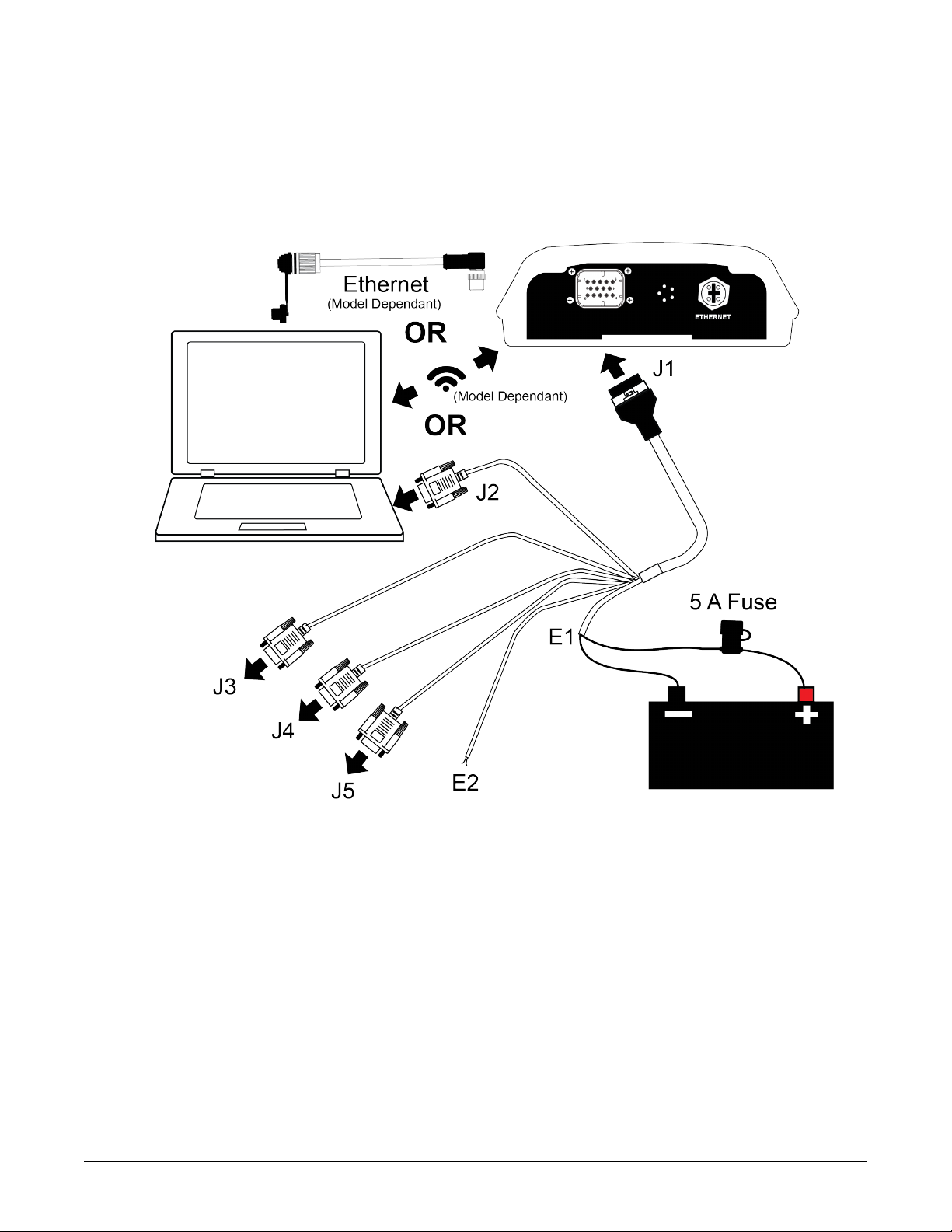
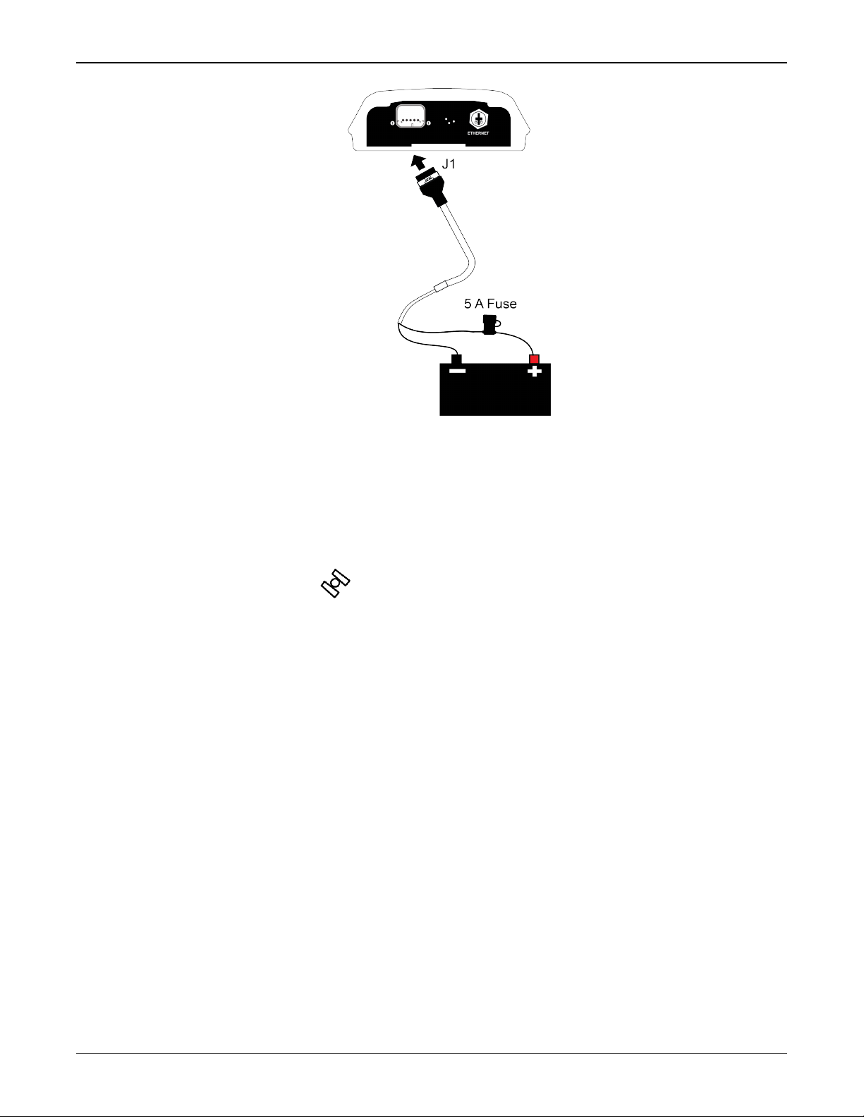
Figure 5: SMART7 Installation
1.
Mount the SMART7 receiver. Refer to Mounting and Orienting the SMART7 on the next page
for mounting details.
2.
Connect other GNSS system components using the output lines.
See SMART7 Interface Cable (Optional Accessory) on page136.
3.
Connect the receiver to other GNSS system components, such as a computer or data terminal, using the communication ports or Wi-Fi.
See Connect the SMART7 to Data Communication Equipment on page24.
4.
Connect the supplied interface cable to the interface connector on the receiver and then connect the power cable to the power supply.
Ensure a 5 A slow blow fuse is incorporated in the power wiring. Refer to SMART7 Interface
Cable (Optional Accessory) on page136 and SMART7 Additional Equipment Required on
SMART7 Installation and Operation User Manual 0C 21
Chapter 2 SMART7 Installation Overview
page28 for fuse recommendations.
See Connect Power to the SMART7 on page26 and Power Supply Requirements for the
SMART7 below for details.
Refer to SMART7 LEDs on page18 for details of SMART7 LED states.
Refer to SMART7 Additional Equipment Required on page28 for fuse recommendations.
2.1 Power Supply Requirements for the SMART7
The SMART7 requires a power supply that provides:
l
a voltage in the range of +7 to +30 VDC
l
at least 15 W of power (typical use: 3 W to 7 W)
See SMART7 Environmental and Electrical Specifications on page133 for more power supply specifications.
The SMART7 has an internal power module that:
l
filters and regulates the supply voltage
l
protects against over-voltage, over-current and high-temperature conditions
l
provides automatic reset circuit protection
If the voltage supplied is below the minimum specification, the receiver suspends
operation. If the voltage supplied is above the maximum specification, the receiver
may be permanently damaged, voiding the warranty.
The supply must be capable of providing enough current to operate the SMART7,
including the initial inrush transient. The supply must also be current limited to 5 A
with an external fuse.
The amount of power required depends on the number of constellations and signals
tracked, and the features enabled.
Refer to SMART7 Interface Cable (Optional Accessory) on page136 for details about the power
cable.
2.2 Mounting and Orienting the SMART7
2.2.1 Mounting
Mount on a secure, stable structure capable of safe operation in the specific environment.
l
If installing on a vehicle, mount the SMART7 on the vehicle roof, ideally close to the pivot
point of the vehicle. The SMART7 must be mounted with the connector facing the rear of the
vehicle.
SMART7 Installation and Operation User Manual 0C 22
Chapter 2 SMART7 Installation Overview
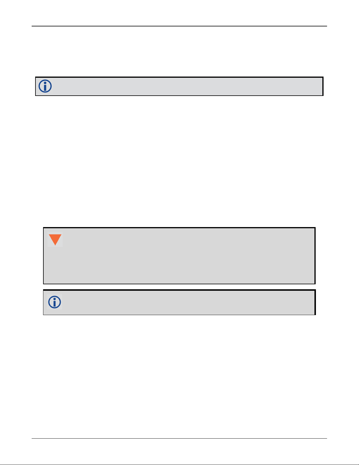
Figure 6: SMART7 Magnetic Mounting Plate
The SMART7 must be rigidly secured to the vehicle to avoid errors caused by vibration
and motion.
l
If installing in a stationary location, mount the SMART7 in a location that has a clear view of
the sky so that each satellite above the horizon can be tracked without obstruction. For more
information, refer to An Introduction to GNSS.
Refer to SMART7 Mounting Plate Specifications on page138 for plate dimensions and mounting
hole locations.
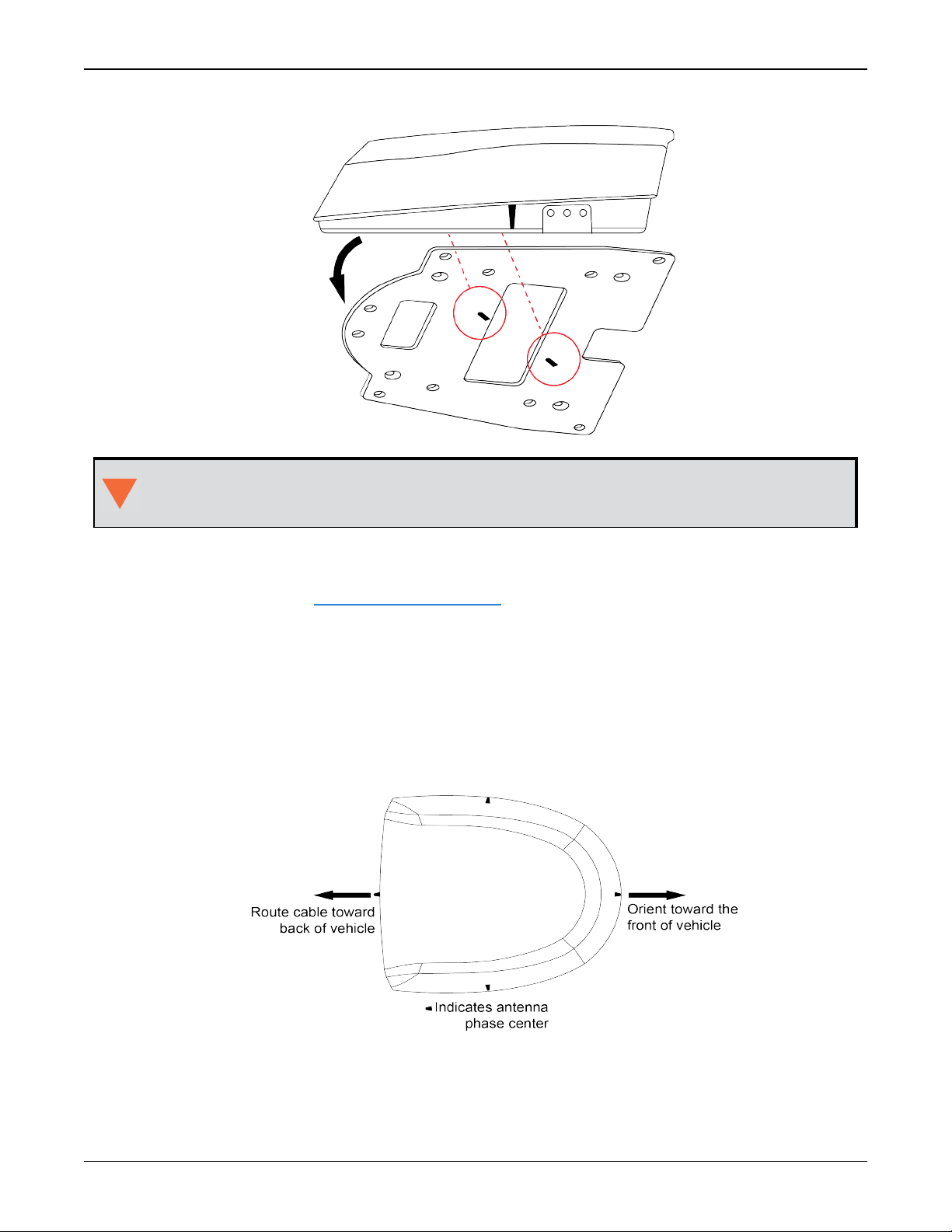
2.2.2 Orienting
Ensure the SMART7 is oriented with the connector(s) facing the back of the vehicle.
Figure 7: SMART7 Orientation
2.2.3 SMART7 and SMART6 Mounting Hole Locations
SMART7 Installation and Operation User Manual 0C 23
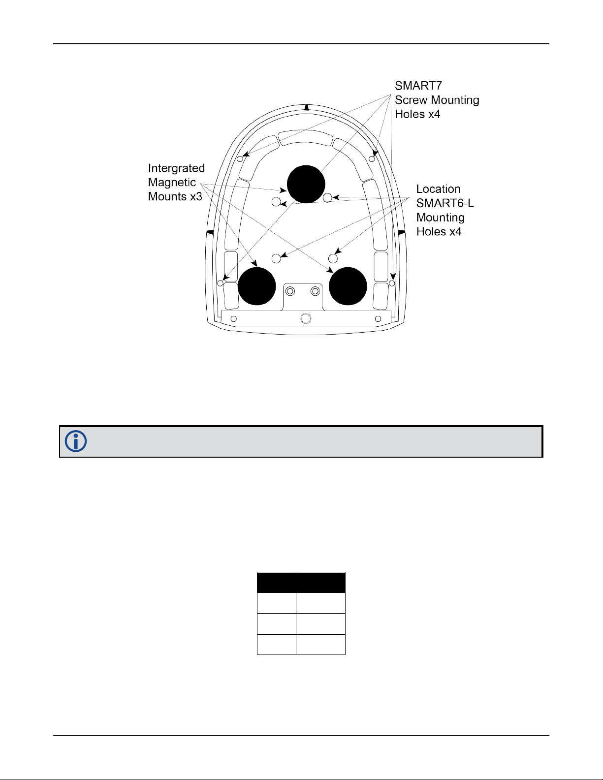
Chapter 2 SMART7 Installation Overview
Figure 8: SMART7 and SMART6 Mounting Hole Locations
2.3 Connect the SMART7 to Data Communication Equipment
The SMART7 can communicate with other devices in the system, such as computers Wi-Fi or Ethernet ports. The SMART7 also has a CAN bus port for communication with other CAN bus compatible devices.
Wi-Fi and Ethernet are model dependent.
2.3.1 Serial Ports
The SMART7 has three serial ports: COM1, COM2 and COM3. These ports are available on the
HD26 COM PORTS connector. Refer to Connect I/OSignals to the SMART7 on page26 for the pin
out of this connector.
Table 7:
SMART7 Serial
Port Protocol
Port RS-232
COM1 Yes
COM2 Yes
COM3 Yes
Use the SERIALCONFIG command to configure the receiver’s asynchronous serial port com-
munications drivers.
SMART7 Installation and Operation User Manual 0C 24
Chapter 2 SMART7 Installation Overview
Port settings (bit rate and parity, for example) are software configurable. See Communications
with the Receiver on page30 for information about configuring the serial ports. Also see
SMART7 Data Communication Specifications on page134 for the serial port specifications.
To connect to a serial port:
1.
Connect the SMART7 Interface cable (PN: 01019944), or a custom made cable, to the HD26
COM PORTS connector.
For information about the SMART7 interface cable refer to Connect I/OSignals to the
SMART7 on the next page.
2.
Connect the appropriate DB9 connector (COM1, COM2 or COM3) to the serial port on the computer or other data communication device.
2.3.2 Wi-Fi
The SMART7 has a Wi-Fi Access Point that is enabled by default. This provides for easy connection to any laptop/tablet/smartphone with Wi-Fi capability and a web browser.
1.
Once the receiver is installed and powered, use a Wi-Fi capable laptop/tablet/smartphone to
locate the SMART7 in the list of detected Wi-Fi Networks and establish a connection.
The SMART7 PSN of the receiver (SSID) is printed on a label located by the connector. The
format of the PSN is SMART7-<Receiver PSN>, e.g. "SMART7-ABCDEF1234567".
2.
A prompt for a password will appear. The default password is printed on a label on the bottom of the SMART7. The default password is specific to that SMART7 receiver.
3.
Open up a web browser and enter any web address (e.g., novatel.com). The SMART7 automatically redirects you to the NovAtel Web User Interface which is hosted on the SMART7.
NovAtel Web User Interface is compatible with recent versions of Chrome, Firefox, Internet Explorer and Safari.
Cookies should always be on and never blocked on the browser being used to connect to
the Wi-Fi network.
For more information about using the NovAtel Web User Interface, refer to the online OEM7 documentation (docs.novatel.com/OEM7).
To change the configuration of the Wi-Fi interface, including password, refer to SMART7-I and
SMART7-W Wi-Fi Configuration Overview on page81.
2.3.3 Ethernet Port
The SMART7 has an M12 D-code (female) socket that supports 10Base-T/100Base-TX Ethernet
for communications with external data communications equipment such as computers and data
loggers. The Ethernet port supports IPv4 Internet layer, TCP/IP transport, ping and connection
from a Telnet client. Users can conduct remote debugging, accept MRTCA (modified RTCA) data
and download firmware. OEM7 receivers are also equipped with NTRIP Version 2.0 (Networked
Transport of RTCM via Internet Protocol) client and server capability.
Refer to Ethernet Configuration on page91 for instructions on configuring Ethernet and NTRIP.
SMART7 Installation and Operation User Manual 0C 25
Chapter 2 SMART7 Installation Overview
2.3.4 CAN Bus Port
The SMART7 has a CAN Bus port available on the 14-Pin interface connector.
To connect to the CANBus port:
1.
Connect the SMART7 optional accessory cable or a custom made cable, to the main 14-Pin
interface connector.
For information about the SMART7 interface cable, see SMART7 Interface Cable (Optional
Accessory) on page136. This section also has the connector pin out and connector recommendations for making a custom cable.
2.
Connect the CAN to the CANBus (J5) of the SMART7 interface cable, see SMART7 Interface
Cable (Optional Accessory) on page136.
The SMART7 CAN bus port is unterminated. If the SMART7 is at the end of the bus, then
the connecting cable must have 120 ohms integrated into the cable between CAN1+ and
CAN1- in close proximity to the main 14-Pin interface connector.
2.4 Connect I/OSignals to the SMART7
The SMART7 has several outputs, also referred to as strobes, that provide status and synchronization signals.
l
Pulse Per Second (PPS) output
l Emulated Radar Output
For more information about the I/O signals, refer to the .
To access the I/O signals, connect the SMART7 interface cable or a custom made cable, to the
main 14-Pin interface connector. Refer to SMART7 Interface Cable (Optional Accessory) on
page136 for connector pin out and other details.
2.5 Connect Power to the SMART7
To connect power to the SMART7:
1.
Connect the SMART7 Interface Cable (01019944) to the 14-Pin connector on the back of the
SMART7. See SMART7 Interface Cable (Optional Accessory) on page136 for information
about this cable.
2.
Connect the BATT+ and BATT- bare wires of the interface cable to a 7 to 30 VDC power supply.
For details about the power supply required, see Power Supply Requirements for the
SMART7 on page22.
2.5.1 Fuse for the Power Supply
Install a user supplied 5 A slow blow fuse in the positive line of the connection to the power
source to protect the power supply wiring and your warranty.
SMART7 Installation and Operation User Manual 0C 26
Chapter 2 SMART7 Installation Overview
Refer to SMART7 Additional Equipment Required on the next page for fuse recommendations.
2.6 Check that the SMART7 is Working
After the SMART7 is installed and powered up, use the following procedure to ensure the
receiver is operating.
1.
Check that the Status LED Fast Flashes Yellow (readystate).
The Status LED may briefly flash as Red before moving quickly to the Fast Flash Yellow.
See SMART7 LEDs on page18 for the location of the LEDs.
2.
Send the following command:
LOG VERSION
The VERSION log is returned.
[COM1]<VERSION COM1 0 92.5 UNKNOWN 0 6.784 02440000 3681 15089
<8
<GPSCARD "DDNRNNTBN" "BMHR18040357C" "OEM7700-1.01"
"OA7CR0501RN0000" "OM7BR0002RB0000" "2018/Sep/20" "05:37:06"
<OEM7FPGA "" "" "" "OMV070001RN0000" "" "" ""
<APPLICATION "" "" "" "ES7AR0501RN0000" "" "2018/Sep/20" "05:37:19"
<DEFAULT_CONFIG "" "" "" "ES7CR0501RN0000" "" "2018/Sep/20"
"05:37:29"
<PACKAGE "" "" "" "ES7PR0501RN0000" "" "2018/Sep/20" "05:37:24"
<DB_WWWISO "WWWISO" "0" "" "WMC010204RN0001" "" "2018/Sep/26"
"10:07:36"
<ENCLOSURE "" "NMPY18070006T" "0.0.0.0" "" "" "" ""
<REGULATORY "US" "" "" "" "" "" ""
SMART7 Installation and Operation User Manual 0C 27
Chapter 2 SMART7 Installation Overview
3.
Check that the Time Status is FINESTEERING which represents that time is fine set and
being steered.
4.
Check the Receiver Status word (02004020 in this example). If the lowest bit (bit 0) is set,
the receiver has errors.
For information about the other digits in Receiver Status word, refer to the
RXSTATUS log in the Agriculture Commands and Logs Reference Manual.
2.7 SMART7 Additional Equipment Required
In order for the SMART7 to perform optimally, the following additional equipment is required:
l
A computer (user supplied)
l
A cable harness for communicating with and powering the SMART7 (NovAtel SMART7 Interface cable is available with four DB-9 connectors, six bare cables and a SMART7 connector
(refer to SMART7 Accessories and Replacement Parts on page139
l
A fused power supply (user supplied)
Table 8: SMART7 Recommended Fuse and Fuse Holders
Fuse Recommended Fuse/Fuse Holder
12 V System Fuse
(standard size
blade)
12 V System Fuse
(mini size blade)
24 V System Fuse
High Reliability,
Harsh
Environment
(standard size
blade)
Inline Fuse
Holder, (for
standard size
blade)
Inline Fuse
Holder, (for mini
size blade)
ATO Silver Blade Fuse 5 A (32 V) or
equivalent
Littelfuse 0287005
Mini Blade Fuse 5 A (32 V) or equivalent Littelfuse 0297005
FKS ATO Blade Fuse 5A (80 V) or
equivalent
Littelfuse 166.7000.450
Waterproof ATO Fuse Holder Littelfuse FHAC0001
Waterproof Mini Fuse Holder Littelfuse 0FHM0001
SMART7 Installation and Operation User Manual 0C 28

Chapter 2 SMART7 Installation Overview
The Recommended Fuse and Fuse Holders table details the part numbers for recommended fuses and fuse holders. These numbers are provided for information only and
are not available from NovAtel as separate parts.
SMART7 Installation and Operation User Manual 0C 29
SMART7 Operation
Before operating the receiver for the first time, refer to SMART7 Installation Overview on
page21 for SMART7 installation instructions.
Refer to Communications with the Receiver below to begin configuring the SMART7 for operation.
3.1 Communications with the Receiver
Communication is established with the receiver using a data terminal or computer connected to
the receiver by a variety of methods:
l
SMART7-I and SMART7-W Wi-Fi Configuration Overview on page81
l
Serial Port Communications below
l
Ethernet Communications on page32
l
ICOM Communications on page32
l
CAN Bus Communications on page33
When connected to the receiver, enter commands directly from a terminal or through terminal
emulation software on a computer. For example:
l
NovAtel Web User Interface - The NovAtel Web User Interface is installed on OEM7
receivers. Refer to the online OEM7 documentation (docs.novatel.com/OEM7) for instruc-
tions.
l
NovAtel Connect - NovAtel Connect is a software application used to monitor and configure
NovAtel receivers. For information about installing and using NovAtel Connect, refer to the
help file included with the application.
NovAtel Connect version 2.0 or greater is required for OEM7 receivers.
Download the latest NovAtel Connect software and documentation from
www.novatel.com/novatel-connect.
l
Any console/command line application
To maximize the application of the receiver’s capabilities, become familiar with the commands
and logs described in Agriculture Commands and Logs Reference Manual.
3.1.1 Serial Port Communications
The receiver can communicate with a computer or terminal via a serial port. For communication
to occur, both the receiver and the operator interface have to be configured properly. The
receiver’s default port settings are:
l
9600 bps
l
no parity
l
8 data bits
l
1 stop bit
SMART7 Installation and Operation User Manual 0C 30
 Loading...