

Novatel SMART6 User Manual

SMART6™
User Manual
OM-20000150 Rev 3 August 2014

SMART6 User Manual
Revision Level: 3
Publication Number: OM-20000150
Revision Date: August 2014
Warranty
NovAtel® Inc. warrants that its GNSS products are free from defects in materials and workmanship, subject to
the conditions set forth on our web site: www.novatel.com/products/warranty/.
Antenna Module One (1) Year
Cables and Accessories Ninety (90) Days
Software Warranty One (1) Year
Return Instructions
To return products, refer to the instructions found under the Return Policy tab on the Warranty page:
www.novatel.com/products/warranty/.
Proprietary Notice
Information in this document is subject to change without notice and does not represent a commitment on the
part of NovAtel Inc. The software described in this document is furnished under a license agreement or nondisclosure agreement. The software may be used or copied only in accordance with the terms of the
agreement. It is against the law to copy the software on any medium except as specifically allowed in the
license or non-disclosure agreement.
The information contained within this manual is believed to be true and correct at the time of publication.
NovAtel, GLIDE, NovAtel Connect and OEM6 are registered trademarks of NovAtel Inc.
SMART6 is a trademark of NovAtel Inc.
The Bluetooth word mark and logos are registered trademarks owned by Bluetooth SIG, Inc. and any use of
such marks by NovAtel Inc. is under license. All other brand names are trademarks of their respective
holders.
Manufactured and protected under U.S. Patent:
#5,390,207 #6,243,409 B1 #7,250,916
#5,495,499 #6,445,354 B1 #7,738,536 B2
#5,734,674 #6,452,560 B2 #7,738,606 B2
#5,809,064 #6,608,998 B1 #7,885,317 B2
#5,736,961 #6,664,923 B1 #8,467,433 B2
#6,184,822 B1 #6,728,637 B2 #8,442,097 B2
#6,211,821 B1 #6,922,167 B2
© Copyright 2014 NovAtel Inc. All rights reserved. Unpublished rights reserved under International copyright
laws.
SMART6 User Manual Rev 3 2

Table of Contents
Notice 7
Customer Service 9
1 Introduction 10
1.1 Features and Models.................................................................................................................................................. 10
1.2 Conventions................................................................................................................................................................ 11
2 Installation and Setup 12
2.1 Additional Equipment Required .................................................................................................................................. 12
2.1.1 SMART6 Setup................................................................................................................................................. 12
2.1.2 Power Supply Requirements............................................................................................................................ 14
2.1.3 Mounting Plate.................................................................................................................................................. 14
2.1.4 Mounting the SMART6 ..................................................................................................................................... 16
2.1.5 Connecting Data Communications Equipment................................................................................................. 16
2.2 Additional Features and Information........................................................................................................................... 17
2.2.1 Status Indicators............................................................................................................................................... 17
2.2.2 MKI and PPS Strobes....................................................................................................................................... 17
2.2.3 Emulated Radar (ER) ....................................................................................................................................... 18
2.2.4 Controller Area Network (CAN) ........................................................................................................................ 18
2.2.5 Tilt Compensation............................................................................................................................................. 18
3 Operation 21
3.1 Communications with the Receiver ............................................................................................................................ 21
3.1.1 Serial Port Default Settings .............................................................................................................................. 21
3.1.2 Communicating Using a Remote Terminal....................................................................................................... 21
3.1.3 Communicating Using a Computer................................................................................................................... 21
3.2 Getting Started............................................................................................................................................................ 22
3.2.1 Starting the Receiver........................................................................................................................................ 22
3.2.2 Communicating with the Receiver Using NovAtel Connect.............................................................................. 22
3.3 Transmitting and Receiving Corrections..................................................................................................................... 23
3.3.1 Base Station Configuration............................................................................................................................... 25
3.3.2 Rover Station Configuration ............................................................................................................................. 26
3.3.3 GPS + GLONASS Base and Rover Configuration ........................................................................................... 26
3.3.4 Configuration Notes.......................................................................................................................................... 27
3.4 GLIDE......................................................................................................................................................................... 28
3.4.1 Dual-Frequency GLIDE .................................................................................................................................... 28
3.5 Steadyline................................................................................................................................................................... 28
3.5.1 Maintain............................................................................................................................................................ 29
3.5.2 Transition.......................................................................................................................................................... 29
3.5.3 Prefer Accuracy................................................................................................................................................ 29
3.5.4 UAL................................................................................................................................................................... 30
3.6 Emulated Radar (ER) ................................................................................................................................................. 31
3.7 Tilt Compensation....................................................................................................................................................... 32
3.8 Recommended Configuration..................................................................................................................................... 33
4 Bluetooth Configuration 34
4.1 Bluetooth Wireless Technology on the SMART6 receiver.......................................................................................... 34
4.2 Pairing with a new SMART6....................................................................................................................................... 34
4.3 Determining the Bluetooth Serial Port ........................................................................................................................ 37
4.4 Communicate with the SMART6 Using Bluetooth Wireless Technology.................................................................... 40
5 NovAtel Firmware and Software 41
5.1 Firmware Updates and Model Upgrades.................................................................................................................... 41
5.1.1 Firmware Updates ............................................................................................................................................ 41
5.1.2 Model Upgrades ............................................................................................................................................... 42
5.2 Authorization Code ..................................................................................................................................................... 42
5.3 Updating or Upgrading Using the WinLoad Utility ...................................................................................................... 43
SMART6 User Manual Rev 3 3

Table of Contents
5.3.1 Transferring Firmware Files.............................................................................................................................. 43
5.3.2 Using the WinLoad Utility ................................................................................................................................. 44
5.4 Updating Using SoftLoad Commands ........................................................................................................................ 45
5.4.1 SoftLoad Commands and Logs........................................................................................................................ 46
5.4.2 Working With S-Records .................................................................................................................................. 46
5.4.3 Sending Firmware Data.................................................................................................................................... 47
5.4.4 SoftLoad Update Method.................................................................................................................................. 48
5.4.5 SoftLoad Errors ................................................................................................................................................ 50
5.5 Upgrading Using the AUTH Command....................................................................................................................... 50
5.5.1 Upgrade Procedure .......................................................................................................................................... 50
A Technical Specifications 51
A.1 SMART6 Receiver Performance ................................................................................................................................ 51
A.2 SMART6 Specifications.............................................................................................................................................. 52
A.2.1 SMART6 Communication/Power Cable (01018999)........................................................................................ 55
A.2.2 SMART6 Connector and Cable Requirements ................................................................................................ 56
B Commands 58
B.1 Syntax Conventions ................................................................................................................................................... 58
B.2 BTCONTROL Enable/Disable Bluetooth wireless technology................................................................................. 59
B.3 COM Configure COM Port....................................................................................................................................... 60
B.4 FRESET Clear Selected Data from NVM and Reset............................................................................................... 61
B.5 LOG Request Logs from the Receiver..................................................................................................................... 63
B.6 $PMDT Configure Tilt Compensation ...................................................................................................................... 66
B.7 RADARCFG Configure the ER Output .................................................................................................................... 67
B.8 SERIALCONFIG Configures serial port settings ..................................................................................................... 68
B.9 SETCANNAME Sets the CAN name fields.............................................................................................................. 70
C Logs 71
C.1 Position Logs.............................................................................................................................................................. 71
C.1.1 NMEA Logs...................................................................................................................................................... 71
C.1.2 NovAtel Position Logs...................................................................................................................................... 72
C.2 Other Logs ................................................................................................................................................................. 72
C.2.1 RADARSIGNAL ER Signal and Position Information.................................................................................... 73
C.2.2 TILT Compensation....................................................................................................................................... 76
C.2.3 VERSION HW and SW Versions and Serial Numbers.................................................................................. 76
D Replacement Parts 77
D.1 SMART6..................................................................................................................................................................... 77
D.2 User Manuals............................................................................................................................................................. 77
SMART6 User Manual Rev 3 4

Figures
1 SMART6 Receiver .................................................................................................................................................... 10
2 SMART6 Connector ................................................................................................................................................. 12
3 Simplified SMART6 Setup ........................................................................................................................................ 13
4 SMART6 Surface Mounting Plate (01018317) ......................................................................................................... 14
3 SMART6 Pole Mounting Plate (01019142) .............................................................................................................. 15
5 SMART6 Orientation ................................................................................................................................................ 16
6 SMART6 Installation ................................................................................................................................................. 19
7 SMART6 Orientation ................................................................................................................................................ 19
8 Open Connection Window ........................................................................................................................................ 22
9 Basic Differential Setup ............................................................................................................................................ 24
10 Positioning Change Without Steadyline ................................................................................................................... 28
11 Steadyline Maintain .................................................................................................................................................. 29
12 Steadyline Transition ................................................................................................................................................ 29
13 Steadyline Prefer Accuracy ...................................................................................................................................... 29
14 Steadyline UAL- Warning Limit Example .................................................................................................................. 30
15 Steadyline UAL - Out of Bounds Example ................................................................................................................ 31
16 SMART6 Tilt Compensation ..................................................................................................................................... 32
17 Bluetooth Icon ........................................................................................................................................................... 34
18 Bluetooth Devices Window ....................................................................................................................................... 35
19 Add a device window ................................................................................................................................................ 35
20 Add a device - Select a pairing option ...................................................................................................................... 36
21 Add a device - Enter pairing code ............................................................................................................................ 36
22 Add a device - Successful ........................................................................................................................................ 37
23 Bluetooth Icon ........................................................................................................................................................... 37
24 Bluetooth Devices Window ....................................................................................................................................... 38
25 Bluetooth Devices Window - Device Menu ............................................................................................................... 39
26 Bluetooth Devices Window - Properties ................................................................................................................... 39
27 Properties - Services Tab ......................................................................................................................................... 40
28 WinLoad’s Open Window ......................................................................................................................................... 44
29 Open File in WinLoad ............................................................................................................................................... 44
30 COM Port Setup ....................................................................................................................................................... 44
31 Searching for Card ................................................................................................................................................... 45
32 Authorization Code Window ..................................................................................................................................... 45
33 Upgrade Process Complete ..................................................................................................................................... 45
34 SMART6 Dimensions ............................................................................................................................................... 54
35 SMART6 Communication/Power Cable ................................................................................................................... 55
SMART6 User Manual Rev 3 5

Tables
1 SMART6 Models ....................................................................................................................................................... 10
2 SMART6 Connector Pin-Out ..................................................................................................................................... 12
3 SMART6 LED Status Indicators ................................................................................................................................ 17
4 Available CAN Signals on the SMART6 .................................................................................................................... 18
5 SMART6 Communication/Power Cable Pin-outs ...................................................................................................... 56
6 SMART6 Mating Connectors..................................................................................................................................... 57
7 Recommended Fuse and Fuse Holders.................................................................................................................... 57
8 SMART6 Commands................................................................................................................................................. 58
9 FRESET Target......................................................................................................................................................... 62
10 Detailed Serial Port Identifiers................................................................................................................................... 65
11 Response Modes....................................................................................................................................................... 67
12 SMART6 Logs in Alphabetical Order......................................................................................................................... 72
13 Position or Velocity Type........................................................................................................................................... 74
14 Solution Status .......................................................................................................................................................... 74
15 Component Type....................................................................................................................................................... 76
16 SMART6 Product....................................................................................................................................................... 77
17 Reference User Manuals........................................................................................................................................... 77
SMART6 User Manual Rev 3 6

Notice
The following notices apply to the SMART6.
Changes or modifications to this equipment not expressly approved by NovAtel Inc. could result
in violation of FCC, Industry Canada and CE Marking rules and void the user’s authority to
operate this equipment.
FCC Notices
This device complies with part 15 of the FCC Rules. Operation is subject to the following two conditions: (1) this
device may not cause harmful interference, and (2) this device must accept any interference received, including
interference that may cause undesired operation.
SMART6 has been tested and found to comply with the emission limits for a Class B digital device, pursuant to part
15 of the FCC Rules. The Class B limits are designed to provide reasonable protection against harmful interference
in a residential installation.
This equipment generates, uses, and can radiate radio frequency energy and, if not installed and used in
accordance with the instructions, may cause harmful interference to radio communications. However, there is no
guarantee that interference will not occur in a particular installation. If this equipment does cause harmful
interference to radio or television reception, which can be determined by turning the equipment off and on, the user
is encouraged to try to correct the interference by one or more of the following measures:
• Re-orient or relocate the SMART6
• Increase the separation between the equipment and the SMART6
• Connect the equipment to an outlet on a circuit different from that to which the SMART6 is
connected
• Consult the dealer or an experienced radio/TV technician for help
Changes or modifications not expressly approved by the party responsible for compliance could
void the user's authority to operate the equipment.
In order to maintain compliance as a Class “B” digital device, shielded cables should be used
for the RS-232 serial data ports (Belden 1036A or equivalent) and twisted pair cable should be
used for the CAN port (shielded twisted pair will improve CAN performance in electrically harsh
environments). I/O signals should be referred to signal ground (connector pin 5) and not power
ground (connector pin 9). If I/O signals route to different areas of the vehicle, dedicated signal
grounds for I/O should be spliced into a common connection to connector pin 5 at a point close
to the SMART6.
Industry Canada
SMART6 Class B digital apparatuses comply with Canadian ICES-003.
SMART6 appareils numérique de la classe B sont conforme à la norme NMB-003 du Canada.
This device complies with Industry Canada licence-exempt RSS standard(s). Operation is subject to the following
two conditions: (1) this device may not cause interference, and (2) this device must accept any interference,
including interference that may cause undesired operation of the device.
Le présent appareil est conforme aux CNR d'Industrie Canada applicables aux appareils radio exempts de licence.
L'exploitation est autorisée aux deux conditions suivantes : (1) l'appareil ne doit pas produire de brouillage, et (2)
l'utilisateur de l'appareil doit accepter tout brouillage radioélectrique subi, même si le brouillage est susceptible
d'en compromettre le fonctionnement.
SMART6 User Manual Rev 3 7

Notice
CE
The enclosures carry the CE mark.
"Hereby, NovAtel Inc. declares that this SMART6 is in compliance with the essential requirements and other
relevant provisions of the R&TTE Directive 1999/5/EC, the EMC Directive 2004/108/EC and the RoHS Recast
Directive 2011/65/EU."
WEEE
If you purchased your OEM6 family product in Europe, please return it to your dealer or supplier at the end of its
life. The objectives of the European Community's environment policy are, in particular, to preserve, protect and
improve the quality of the environment, protect human health and utilise natural resources prudently and rationally.
Sustainable development advocates the reduction of wasteful consumption of natural resources and the
prevention of pollution. Waste electrical and electronic equipment (WEEE) is a regulated area. Where the
generation of waste cannot be avoided, it should be reused or recovered for its material or energy. WEEE products
may be recognized by their wheeled bin label ( ).
1
REACH
NovAtel strives to comply with the EU Directive EC 1907/2006 on chemicals and their safe use as per the
Registration, Evaluation, Authorization and Restriction of Chemical substances (REACH) for its products, including
the SMART6 product. Since REACH SVHC lists are updated occasionally, please contact NovAtel Customer
Support if you require further information.
Cables may contain DEHP (CAS Number 117-81-7) in concentrations above 0.1% w/w.
1.Visit the NovAtel Web site at www.novatel.com/products/weee-and-rohs/ for more information on WEEE.
SMART6 User Manual Rev 3 8
Customer Service
NovAtel Knowledge Base
If you have a technical issue, visit the NovAtel support website at www.novatel.com | Support | Helpdesk and
Solutions | Knowledge and Forums. Through this page, you can search for general information about SMART®
antennas and other technologies, information about NovAtel hardware, software, installation and operation issues.
Before Contacting Customer Support
Before you contact NovAtel Customer Support about a software problem perform the following steps:
1. Issue the following logging commands to collect data to a file on your computer for 15 minutes:
LOG VERSIONA ONCE
LOG RXSTATUSA ONCE
LOG RXCONFIGA ONCE
LOG RAWEPHEMA ONNEW
LOG BESTPOSA ONTIME 1
LOG RANGEA ONTIME 1
LOG GLORAWEPHEMB ONCHANGED
2. Send the file containing the logs to NovAtel Customer Service, using either the NovAtel ftp site at ftp://
ftp.novatel.com/incoming or the support@novatel.com e-mail address.
1
3. You can also issue a FRESET command to the receiver to clear any unknown settings.
The FRESET command will erase all user settings and perform a factory reset. You should know
If you are having a hardware problem, send a list of the troubleshooting steps taken and the results.
your configuration and be able to reconfigure the receiver before you send the FRESET
command.
Contact Information
Use one of the following methods to contact NovAtel Customer Support:
Call the NovAtel Hotline at 1-800-NOVATEL (U.S. and Canada) or +1-403-295-4500 (international)
Fax: +1-403-295-4501
E-mail: support@novatel.ca
website: www.novatel.com
Write: NovAtel Inc.
Customer Support Department
1120 - 68 Avenue NE
Calgary, AB
Canada, T2E 8S5
1. For GLONASS channel configuration.
SMART6 User Manual Rev 3 9
Chapter 1 Introduction
The SMART6 is a high performance GNSS receiver and antenna, capable of receiving and tracking different
combinations of GNSS L1/L2 code and carrier signals on a maximum of 120 channels. SBAS (Satellite
Based Augmentation Systems) support, which includes WAAS (North America), EGNOS (Europe) and
MSAS (Japan) is standard. Refer to NovAtel’s GNSS Book for an overview of each of the above signal types.
The SMART6 rear panel also features Light Emitting Diodes (LEDs) for status indication.
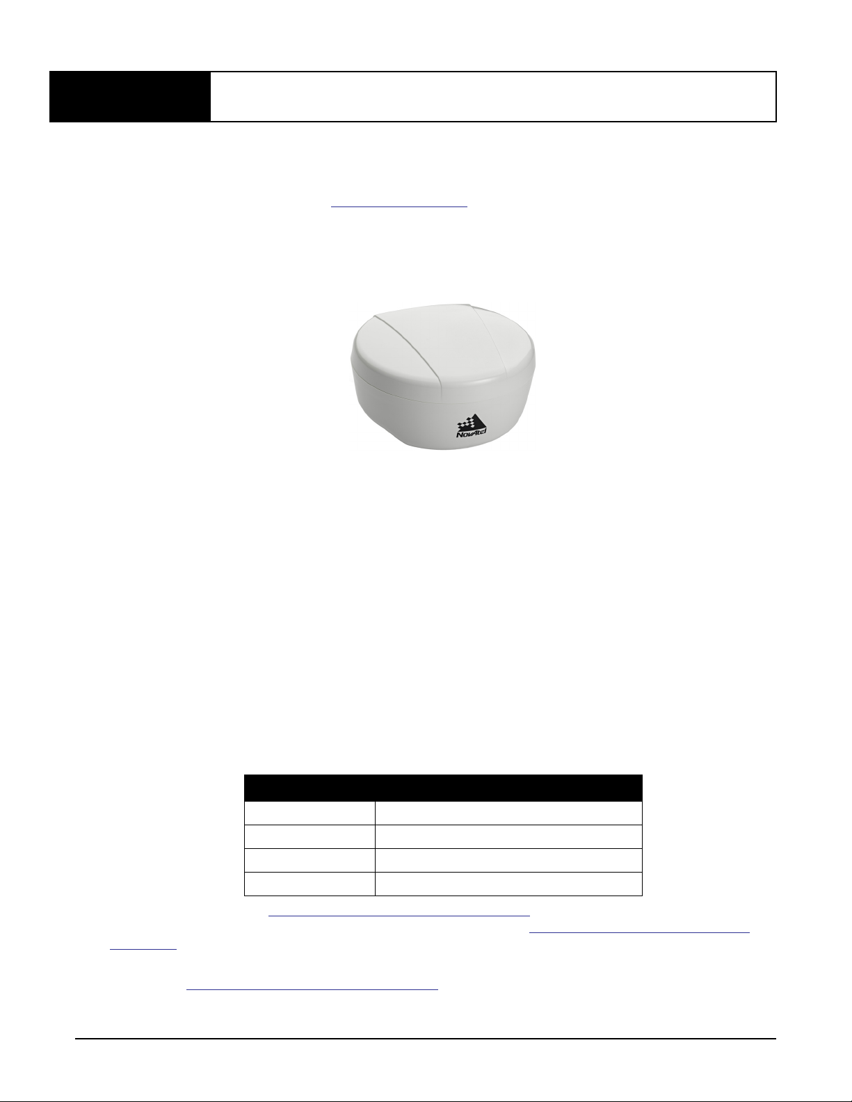
Once properly powered, the SMART6 begins operating as a fully functional GNSS system. Figure 1,
SMART6 Receiver shows the SMART6 without connecting cables.
Figure 1: SMART6 Receiver
1.1 Features and Models
The main features of the SMART6 are:
• an enhanced high performance GNSS L1/L2 receiver
• a high performance GNSS L1/L2 antenna
• a CAN port
• three RS-232 COM ports or
two RS-232 COM ports and Bluetooth
• three LED status indicators
• a water and dust tight enclosure
• Bluetooth wireless technology (optional)
• tilt compensation (optional)
The SMART6 is available in several different firmware models whose configurations may include other
additional features. Some possible configurations can be seen in Table 1, SMART6 Models.
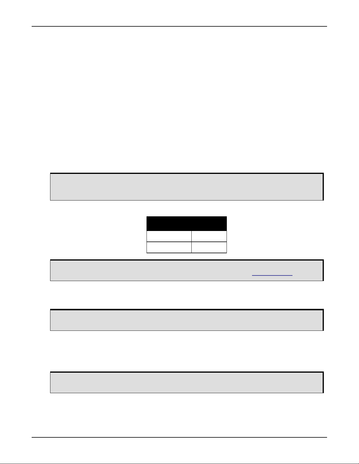
Table 1: SMART6 Models
NovAtel Part # Description
01019123 SMART6
01019125 SMART6 with Tilt
01019121 SMART6 with Bluetooth
01019127 SMART6 with Bluetooth and Tilt
Contact NovAtel Sales at www.novatel.com/where-to-buy/contact-us for information regarding available
models, upgrading a model to increase feature/functionality or go to www.novatel.com/support/firmware-
downloads to obtain product updates. Refer to Chapter 5, NovAtel Firmware and Software on page 41 for
details.
Refer to the OEM6 Installation and Operation Manual for detailed information on receiver communications
and operation.
SMART6 User Manual Rev 3 10

Introduction Chapter 1
1.2 Conventions
Conventions used in this manual are the following:
Note that provides information to supplement or clarify the accompanying text.
Caution that a certain action, operation or configuration may result in incorrect or improper use
of the product.
Warning that a certain action, operation or configuration may result in regulatory
noncompliance, safety issues or equipment damage.
• The letter H in the Offset columns of the commands and logs tables represents the header length for
that command or log. Refer to the
header details.
• The number following 0x is a hexadecimal number.
• Command descriptions’ brackets, [ ], represent the optionality of parameters.
• In tables where values are missing they are assumed to be reserved for future use.
• Status words are output as hexadecimal numbers and must be converted to binary format (and in
some cases then also to decimal). For an example of this type of conversion, refer to the RANGE log
in the OEM6 Family Firmware Reference Manual.
• Conversions and their binary or decimal results are always read from right to left.
OEM6 Family Firmware Reference Manual for ASCII and binary
SMART6 User Manual Rev 3 11
Chapter 2 Installation and Setup
2.1 Additional Equipment Required
In order for the SMART6 to perform optimally, the following additional equipment is required:
• A cable harness for communicating and powering the SMART6 (NovAtel cable harness 01018999 is
available with three DB-9 connectors, four bare cables and a SMART6 connector) or similar
• A fused power supply (user supplied) (refer to Table 7, Recommended Fuse and Fuse Holders on
Page 57 for details)
• A computer (user supplied)
2.1.1 SMART6 Setup
Complete the following steps to connect and power the SMART6.
1. Mount the SMART6 on a secure, stable structure with an unobstructed view of the sky from horizon to
horizon (refer to Section 2.1.4 Mounting the SMART6 on page 16 for details).
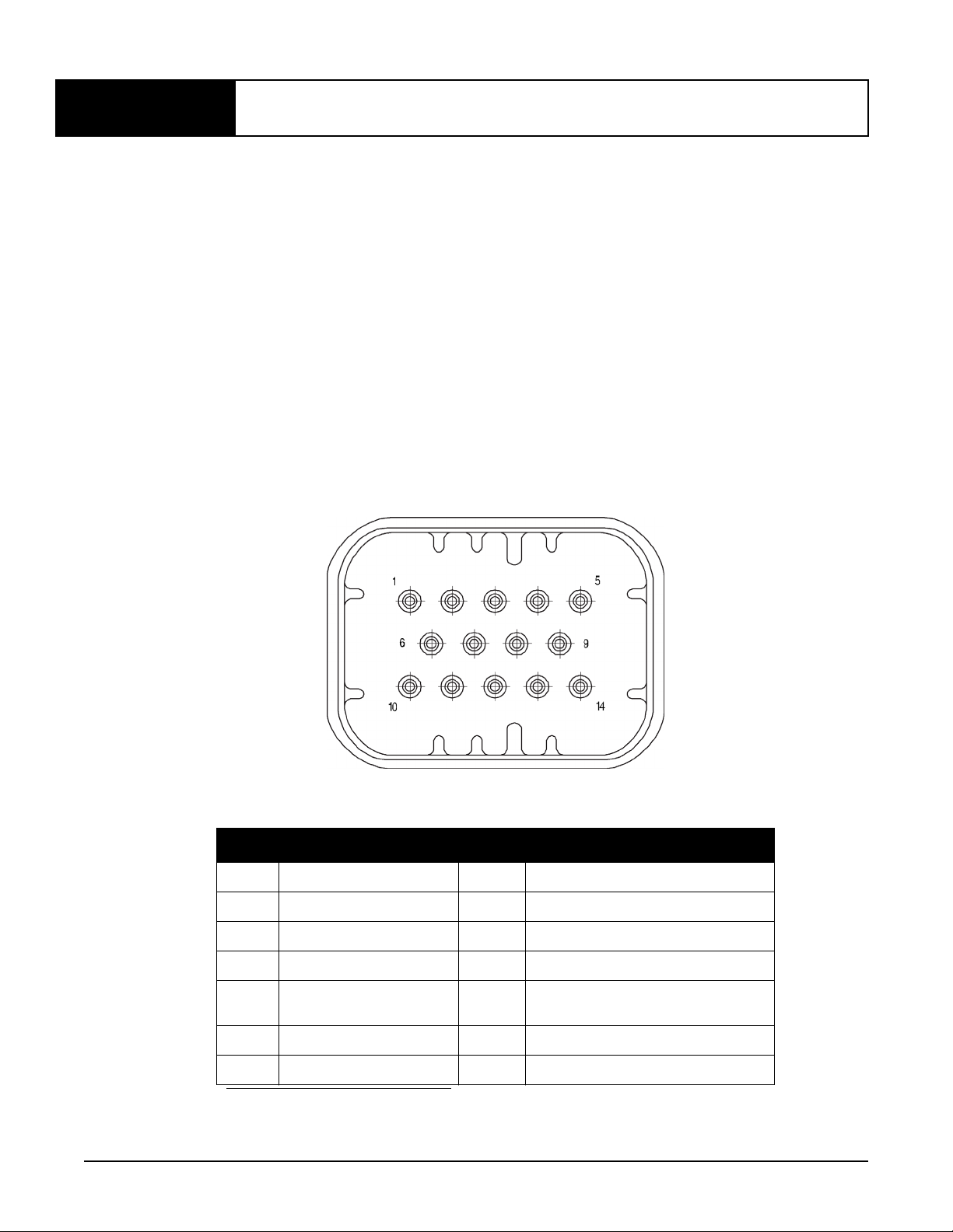
2. Connect the NovAtel interface cable, or custom wiring harness, to the COM and Power port on the back
of the SMART6, see Figure 2, SMART6 Connector.
Figure 2: SMART6 Connector
Table 2: SMART6 Connector Pin-Out
Pin Use Pin Use
1 COM1 TxD 8 AUX TxD
2 COM1 RxD 9 Power Negative/Return
3 COM2 TxD 10 ER_OUT (Emulated Radar Output)
4 COM2 RxD 11 MKI (Mark Input)
5 Signal Ground
(COM/MKI/PPS/ER)
6 CAN+ 13 AUX RxD
7 CAN- 14 Power Positive/Source
a. On Bluetooth models, the AUX port is dedicated for Bluetooth communication
and is not available through the SMART6 connector.
12 PPS (Pulse Per Second) Output
a
a
SMART6 User Manual Rev 3 12
Installation and Setup Chapter 2
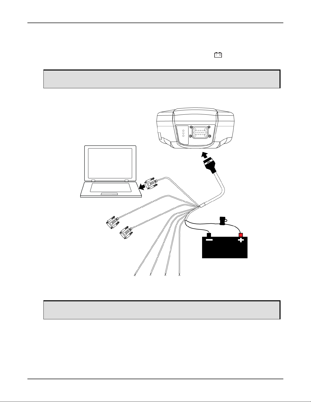
3. Connect the NovAtel cable or custom wiring harness to a DB-9 serial port on a computer or other data
storage device.
4. Connect the NovAtel cable or custom wiring harness to the power supply and turn on the power supply to
the SMART6 (the SMART6 cable is also a power cable). The power LED on the receiver glows red
when the SMART6 is properly powered.
Fuse/holder recommendations can be found in Table 7, Recommended Fuse and Fuse Holders
on Page 57.
Figure 3: Simplified SMART6 Setup
Tyco 14-pin
Connector
COM
COM
AUX
MKI PPS CAN
Minimum conductor size for all wiring is 0.5 mm/20 AWG.
ER_OUT
User supplied
5A fast blow fuse
SMART6 User Manual Rev 3 13

Installation and Setup Chapter 2
2.1.2 Power Supply Requirements
The SMART6 requires +8 to +36 VDC input power (refer to SMART6 Specifications on page 52 for additional
power supply specifications).
The SMART6 cable provides power in (BATT+) and power ground (BATT-) bare wires for connecting the
SMART6 to a vehicular power system (or equivalent).
The SMART6 power source must be protected by a 5 A Fast Blow Fuse or damage to wiring
2.1.3 Mounting Plate
Two mounting plates are available to facilitate mounting the receiver: a surface mounting plate and a pole
mounting plate.
may result (not covered by warranty). Refer to SMART6 Connector and Cable Requirements on
page 56).
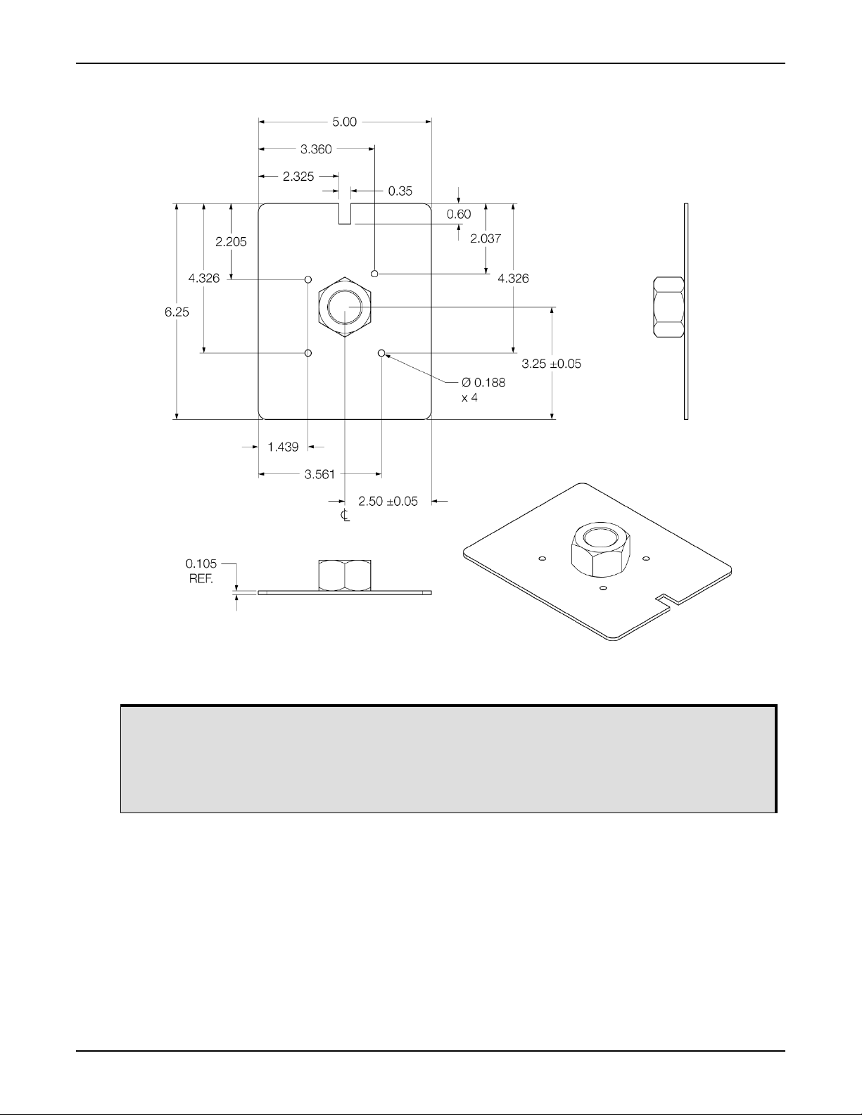
Figure 4: SMART6 Surface Mounting Plate (01018317)
Dimensions are in inches.
To install the mounting plate, use the adhesive tape or the mounting holes at each corner of the
SMART6 User Manual Rev 3 14
plate.
Installation and Setup Chapter 2
Figure 3: SMART6 Pole Mounting Plate (01019142)
All dimensions are in inches
To install the pole mounting plate:
1. Use four M4 screws to connect the mounting plate to the SMART6.
2. Screw the mounting plate onto a mount, such as a range pole, tribrach, or tripod, with a 1" x
14 thread.
A 5/8” to 1” bushing adapter is available (part number 12023275).
SMART6 User Manual Rev 3 15
Installation and Setup Chapter 2
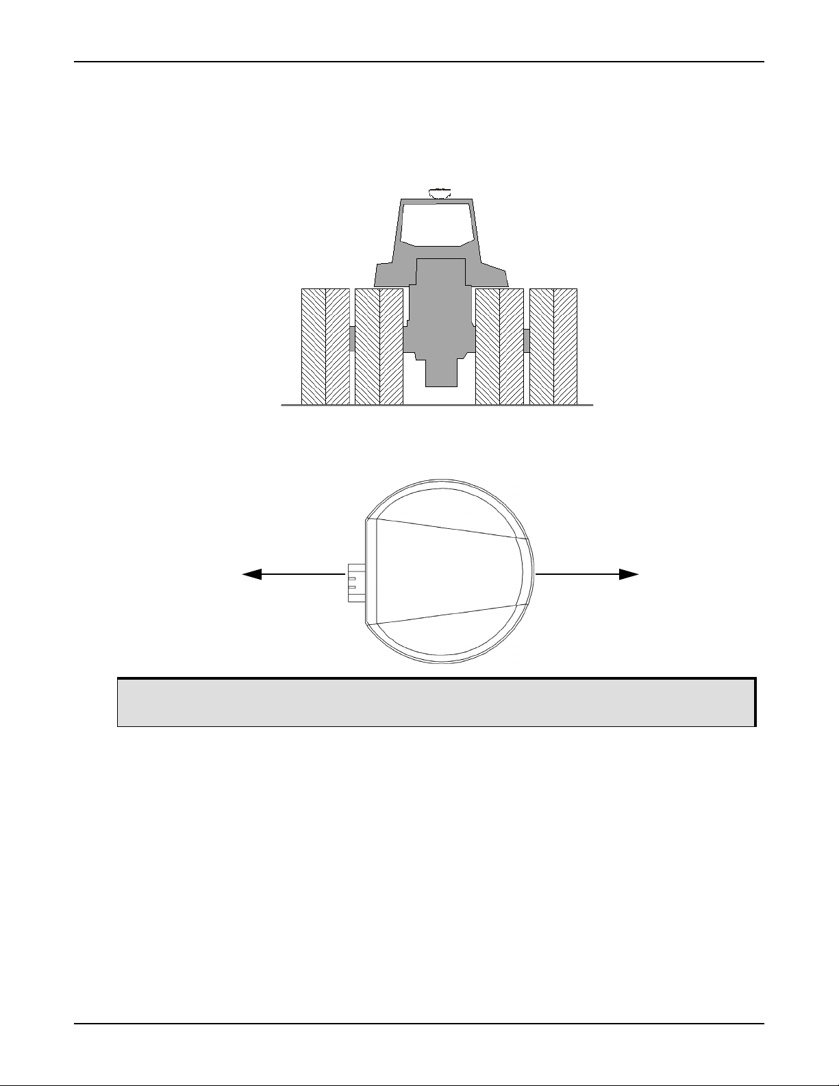
2.1.4 Mounting the SMART6
Mount the SMART6 on a secure, stable structure capable of safe operation in the specific environment.
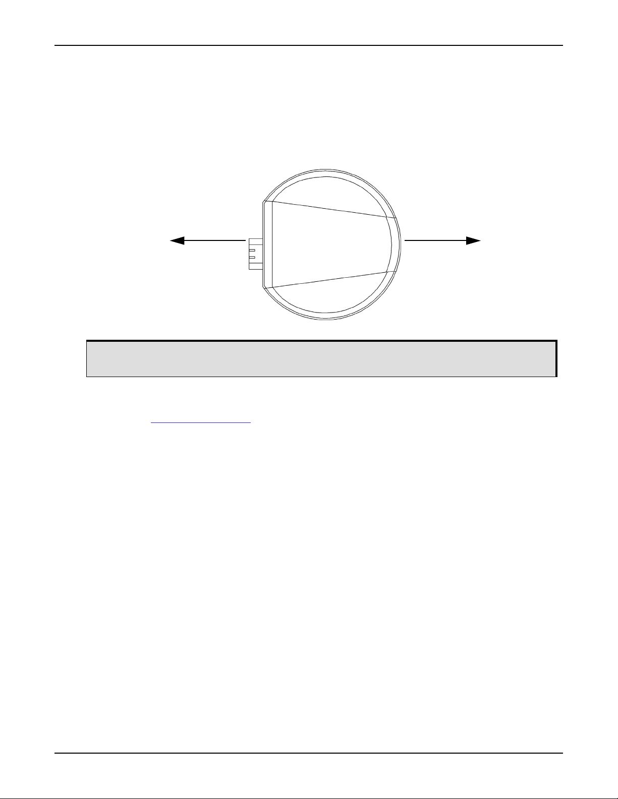
• If installing on a vehicle, mount the SMART6 on the vehicle roof, ideally close to the pivot point of the
vehicle. The SMART6 must be mounted with the connector facing the rear of the vehicle (see
Figure 5, SMART6 Orientation).
Figure 5: SMART6 Orientation
Route cable toward
back of vehicle
The SMART6 must be rigidly secured to the vehicle to avoid errors caused by vibration and
motion.
• If installing in a stationary location, mount the SMART6 in a location that has a clear view of the sky
so that each satellite above the horizon can be tracked without obstruction. For more information,
refer to NovAtel’s GNSS Book.
Orient toward the front
of vehicle
2.1.5 Connecting Data Communications Equipment
To communicate with the receiver for sending commands and obtaining logs, a connection to data
communications equipment is required. Refer to Table 5, SMART6 Communication/Power Cable Pin-outs on
Page 56 on for more information.
SMART6 User Manual Rev 3 16
Installation and Setup Chapter 2
2.2 Additional Features and Information
This section contains information on the additional features of the SMART6, which may affect the overall
design of the receiver system.
2.2.1 Status Indicators
LED indicators on the SMART6 provide the status of the receiver. The table below shows the meaning of the
LEDs.
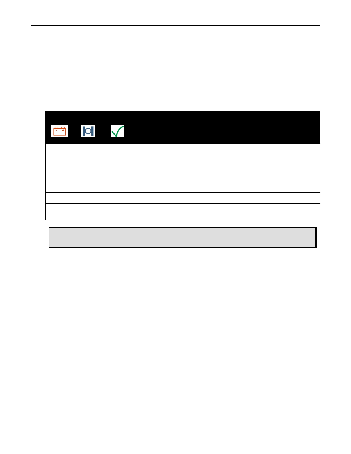
Table 3: SMART6 LED Status Indicators
Red
Off Off Off Power is not available. (Red indicator may also not be lit if a boot failure has
On Off Off Power is available but no satellites are being tracked yet.
On Flashing Off Tracking at least one satellite but not a valid position.
On On Off Position valid in basic autonomous mode.
On On Flashing SBAS tracking, but not enough data for enhanced solution.
On On On Position valid in an enhanced accuracy mode
Troubleshooting:
• If the power is on but the yellow LED does not flash within one minute, then no satellites are being
tracked. There may be excessive blockage or the SMART6 may be defective. Make sure the SMART6
has an unobstructed view of the sky. Try power cycling the SMART6.
• If the yellow LED is flashing but doesn’t progress to solid yellow within one minute, then insufficient
satellites are being tracked or the signal quality is poor and ephemeris data cannot be received.
Normally, four satellites are sufficient for a valid position as long as they are widely distributed in the sky.
If LED is stuck on blinking yellow, there may be excessive signal blockage or the SMART6 may be
defective. Make sure the SMART6 has an unobstructed view of the sky. Try power cycling the SMART6.
• If the yellow LED is on, but the green doesn’t turn on within five minutes than no SBAS or DGPS
positions are available. If you are using SBAS, make sure SBAS is available in your area and that the
SMART6 is configured to enable SBAS positions (SBASCONTROL ENABLE). For DGPS, make sure the
SMART6 is configured with the correct serial port parameters and to accept the DGPS protocol your area
is using and that your data modem is connected and working.
• The green LED blinks when SBAS is detected then it comes on solid when SBAS is enabled. The LED
will stay dark if SBAS is not detected.
Yellow
Flashing means that the LED is turning on and off at a 1 Hz rate - 0.5 seconds on and 0.5
seconds off.
Green
Condition
occurred.)
(WAAS/EGNOS/MSAS/DGPS).
2.2.2 MKI and PPS Strobes
The Mark Input (MKI) and Pulse Per Second (PPS) strobe provide status and synchronization signals. PPS is
a 3.3 V CMOS output; MKI is a 5 V logic tolerant input.
Pin-out information can be found on Table 5, SMART6 Communication/Power Cable Pin-outs on page 56.
SMART6 User Manual Rev 3 17
Installation and Setup Chapter 2
2.2.3 Emulated Radar (ER)
The SMART6 outputs an emulated RADAR signal via the bare wires labeled ER GND and ER_OUT on the
SMART6 cable. See Table 5, SMART6 Communication/Power Cable Pin-outs on page 56 for the pin-out
details of this cable.
The ER outputs a logic high of supply voltage minus 0.5 V minimum and logic low of 0.5 V maximum with a
rise and fall time of less than 1 ms. Its output references signal GND and provides logic low output until its
speed is greater than 1 km/Hr. ER can be configured to operate at one of three distinct frequencies (26.11,
28.12 or 36.11 Hz/km/Hr, with 26.11 Hz/km/Hr being the default value) and with an effective range from 1 km/
Hr to 55 km/Hr for near-horizontal applications. See Section B.7, RADARCFG Configure the ER Output on
page 67 for more information.
2.2.4 Controller Area Network (CAN)
The SMART6 supports the following NMEA2000 Parameter Group Messages (PGN):
• PGN 129029 GNSSPositionData (1 Hz)
• PGN 129025 GNSSPositionRapidUpdate (10 Hz)
• PGN 129026 COGandSOGRapidUpdate (10 Hz)
The CAN must be activated by entering the SETCANNAME command (refer to B.9
SETCANNAME Sets the CAN name fields on page 70). To have the CAN set up automatically
at subsequent start ups, also send the SAVECONFIG command.
Table 4: Available CAN Signals on the SMART6
CAN Pins
CAN+ Pin 6
CAN- Pin 7
Details for the PGN messages can be found in the NMEA2000 specification which can be
purchased directly from the National Marine Electronics Association (www.nmea.org/).
2.2.5 Tilt Compensation
The SMART6 Tilt Compensation feature corrects for errors in position caused by tilting of the vehicle.
Refer to Tilt Compensation on page 32 for a detailed description of the Tilt Compensation
To fully install and set up tilt compensation:
1. Mount the SMART6 on the vehicle.
2. Measure, set and save the height of the SMART6 from the ground.
3. Level the tilt sensor and save the data.
feature.
Refer to $PMDT Configure Tilt Compensation on page 66 for height, level and update
commands.
SMART6 User Manual Rev 3 18
Installation and Setup Chapter 2
2.2.5.1 Physical Installation
The SMART6 must be mounted as close to the center of the vehicle as possible, as illustrated in Figure 6,
SMART6 Installation.
Figure 6: SMART6 Installation
SMART6
The SMART6 must be mounted with the connector facing the rear of the vehicle, as shown in Figure 7,
SMART6 Orientation:
Figure 7: SMART6 Orientation
Route cable toward
back of vehicle
Orient toward the front
of vehicle
The SMART6 must be rigidly secured to the vehicle to minimize errors due to vibration and
motion.
2.2.5.2 Height Measurement and Configuration
The height measurement should be made while the vehicle has the correct tire pressure and is parked on a
hard-packed and level surface. The measurement should be made from the ground to the bottom of the
SMART6 connector. The measurement accuracy should be within 1 to 2 inches (2.5 to 5.0 cm).
Once the measurement has been made (in feet and inches, or metres), refer to Section B.6,
$PMDT Configure Tilt Compensation on page 66 for instructions on how to set the height in the SMART6.
The height must be saved after the height command is sent. This must be done so the height data is saved
between power cycles. Instructions on sending the save command are outlined in Section B.6,
$PMDT Configure Tilt Compensation on page 66.
Note that changes in tire pressure over time can potentially cause errors in tilt compensation. This is because
the height of vehicle can vary with tire pressure.
The SMART6 is shipped from the factory with the height set to 0.0 metres.
SMART6 User Manual Rev 3 19

Installation and Setup Chapter 2
2.2.5.3 Leveling the Tilt Sensor
The vehicle must be parked on flat ground when the level command is sent to the SMART6. Refer to
Section B.6, $PMDT Configure Tilt Compensation on page 66 for instructions on how to send the level
command.
After the tilt sensor has been leveled, the data must be saved to non-volatile memory using the save
command. Instructions on using the save command are outlined in Section B.6, $PMDT Configure Tilt
Compensation on page 66.
SMART6 User Manual Rev 3 20

Chapter 3 Operation
Before operating the SMART6 for the first time, ensure the installation instructions in Chapter 2, Installation
and Setup were followed. It is assumed that a computer is used during initial operation and testing for greater
ease and versatility.
3.1 Communications with the Receiver
Communication with the receiver typically consists of issuing commands through the communication ports
from an external serial communications device. This could be either a terminal or computer connected
directly to the receiver serial port using a DB-9 connector on the SMART6 communication/power cable. If
using a radio, connect it to another DB-9 connector on the same communication/power cable by means of
the radio serial cable supplied with the radio. It is recommended that you become thoroughly familiar with the
commands and logs detailed in the OEM6 Family Firmware Reference Manual to ensure maximum utilization
of the receiver’s capabilities.
3.1.1 Serial Port Default Settings
The receiver communicates with the computer or terminal via an RS-232 serial port. For communication to
occur, both the receiver and the operator interface have to be configured properly. The receiver’s COM1 and
COM2 default port settings are:
• 9600 bps, no parity, 8 data bits, 1 stop bit, no handshaking, echo off
The receiver’s AUX default port settings are:
• 9600 bps, no parity, 8 data bits, 1 stop bit, no handshaking, echo off
To change the default settings, use the SERIALCONFIG command. See Appendix B.8,
SERIALCONFIG Configures serial port settings starting on Page 68 for details.
The data transfer rate chosen determines how fast information is transmitted. For example, outputting a log
whose message byte count is 96. The default port settings allows 10 bits/byte (8 data bits + 1 stop bit + 1
framing bit). It therefore takes 960 bits per message. To get 10 messages per second, 9600 bps is required.
Also remember that even if the bps is set to 9600, the actual data transfer rate is lower and depends on the
number of satellites being tracked, data filters in use and idle time. It is suggested a margin is set when
choosing a data rate (115200 is recommended for most applications).
Although the receiver can operate at data transfer rates as low as 300 bps, this is not desirable.
For example, if several data logs are active (that is, a significant amount of information needs to
be transmitted every second) but the bit rate is set too low, data will overflow the serial port
buffers, causing a warning in the receiver status and loss of data.
3.1.2 Communicating Using a Remote Terminal
One method of communicating with the receiver is through a remote terminal. The receiver is pre-wired to
allow proper RS-232 interface with the data terminal. To communicate with the terminal, the receiver only
requires the RX, TX and GND lines to be used. Request to Send (RTS)/Clear to Send (CTS) hardware
handshaking is not available. Ensure the terminal’s communications set up matches the receiver’s RS-232
protocol.
3.1.3 Communicating Using a Computer
A computer can be set up to emulate a remote terminal as well as provide the added flexibility of creating
multiple command batch files and data logging storage files. Any standard communications software
package, that emulates a terminal, can be used to establish bidirectional communications with the receiver.
For example, HyperTerminal or NovAtel’s Graphical User Interface (GUI) program NovAtel Connect™. All
data is sent as raw 8-bit binary or ASCII characters.
SMART6 User Manual Rev 3 21
Operation Chapter 3
3.2 Getting Started
3.2.1 Starting the Receiver
When first powered, the SMART6 undergoes a complete self-test. The results of this test can be viewed by
connecting to the receiver and requesting the RXSTATUS log. Refer to the OEM6 Family Firmware
Reference manual for details.
If a persistent error develops, contact your local NovAtel dealer first. If the problem remains unresolved,
contact NovAtel directly through any of the methods listed in the Customer Service section on page 9.
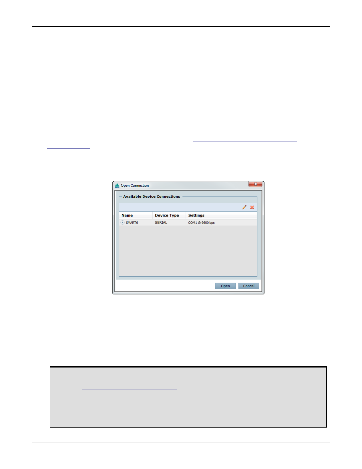
3.2.2 Communicating with the Receiver Using NovAtel Connect
NovAtel Connect is a Windows based GUI used to access the receiver's many features. Convert is a utility
that converts between file formats and strips unwanted records for data file compilation. Both are included in
the NovAtel Connect PC Utilities bundle available from: www.novatel.com/support/search/items/
PC%20Software.
Launch the NovAtel Connect program and select Device | Open Connect from its main menu. The Open
Connection window appears.
Figure 8: Open Connection Window
Refer to the NovAtel Connect help file or press F1 while the cursor is in a NovAtel Connect window. Ensure
the Console and ASCII Messages windows are open by selecting them from the View menu.
When the receiver is first turned on, no data is transmitted from the COM ports except for the port prompt.
The console window displays a port name:
[COM1] if connected to COM1 port
[COM2] if connected to COM2 port
[AUX] if connected to AUX port or through Bluetooth
Any of the above prompts indicate the receiver is ready and waiting for command input.
1. You may also have to wait for output from receiver self-tests. For example, on start-up, the
SMART6 User Manual Rev 3 22
SMART6 is set to log the RXSTATUSEVENTA log ONNEW on all ports. Refer to the OEM6
Family Firmware Reference Manual for more details.
2. If NovAtel Connect is unable to locate the SMART6, try using a different COM port to
communicate to the receiver. Once communication has been established, issue the FRESET
STANDARD command. You should now be able to use the original communication port again.
3. When using the AUX port, you must use a “Passive” connection in NovAtel Connect.

Operation Chapter 3
Commands are typed at the interfacing computing device’s keypad and executed after issuing a carriage
return command which is usually the same as pressing the <Enter> key.
An example of a response to an input command is the FIX POSITION command. It can be as:
[COM2] FIX POSITION 51.11635 -114.0383 1048.2 [Carriage Return]
<OK
where [COM2] is the port prompt, followed by the command entered and [Carriage Return] is a prompt to
press the <Enter> key.
The example above illustrates the command input to the base receiver’s COM2 port, which sets the position
of the base station receiver for differential operation. Confirmation that the command was actually accepted is
the appearance of <OK.
If a command is entered incorrectly, the receiver responds with:
<Invalid Message ID (or a more detailed message)
Ensure the computer’s Control Panel Power Settings are not set to Hibernate or Standby
modes. Data is lost if one of these modes occurs during a logging session.
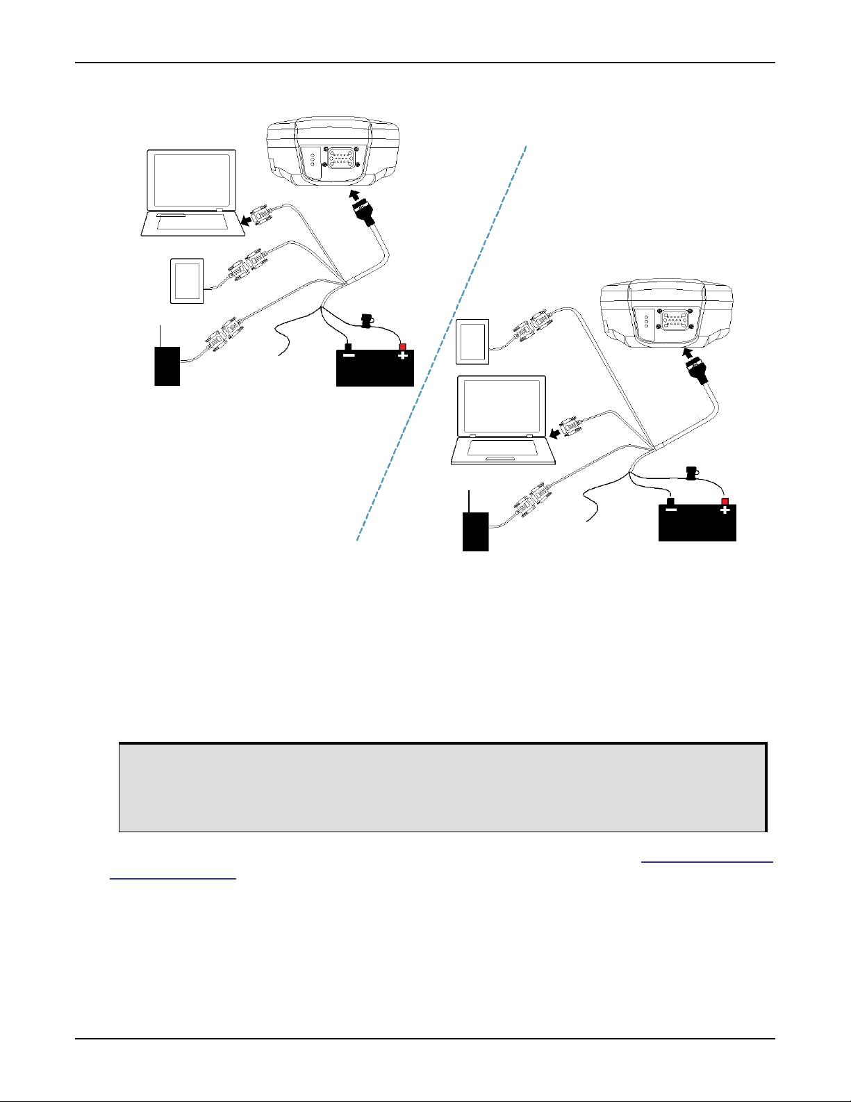
3.3 Transmitting and Receiving Corrections
RTK or DGPS corrections can be transmitted from a base station to a rover station to improve position
accuracy. The base station is the GNSS receiver, which is acting as the stationary reference. It has a known
position and transmits correction messages to the rover station. The rover station is the GNSS receiver which
does not know its exact position and can be sent correction messages from a base station to calculate
differential GNSS positions. The SMART6 can be used as a base receiver to transmit RTK or DGPS
corrections or a rover to receive the same corrections. An example of a differential setup is given in Figure 9,
Basic Differential Setup on page 24.
SMART6 User Manual Rev 3 23
Operation Chapter 3
Figure 9: Basic Differential Setup
4
COM1
7
5
COM2
2
AUX
6
1
Rover
Base
1
5
COM1
3
4
COM2
7
2
AUX
6
3
Reference Description
1 SMART6 receiver
2 User supplied 5 A fast blow fuse
3 User supplied power supply, for example a battery
4 User supplied device to COM1
5 User supplied device to COM2
6 User supplied device to AUX
7 User supplied cable or NovAtel 01018999 Communication/Power cable
The configuration shown in Figure 9, Basic Differential Setup is valid for SMART6 receivers
System biases can introduce errors, refer to our GNSS Book found on our Web site at www.novatel.com/an-
introduction-to-gnss/ for more information. In most cases, a data link between the base station and rover
station (two NovAtel receivers) is required to receive corrections. SBAS corrections can be accomplished
with one receiver and are exceptions to the base/rover concept. Generally, a link capable of data throughput
at a rate of 9600 bits per second and less than 4.0 s latency is recommended.
Once the base and rover are set up, configure them as shown in the configuration examples that follow in
Section 3.3.1, Base Station Configuration on page 25 and Section 3.3.2, Rover Station Configuration on
page 26.
without optional Bluetooth.
For a SMART6 receiver with Bluetooth, two of the serial devices connect through COM1 and
COM2 and the other device must connect through Bluetooth.
SMART6 User Manual Rev 3 24
 Loading...