

Novatel SMART2-B, SMART2, SMART2-TB Installation And Operation User Manual

SMART2
Installation and Operation
User Manual
OM-20000185 1 July 2019

SMART2 Installation and Operation Manual
Publication Number: OM-20000185
Revision Level: 1
Revision Date: July 2019
Firmware Version: 7.06.02 / OA7CR0602RN0000
Warranty
NovAtel Inc. warrants that its GNSS products are free from defects in materials and workmanship, subject to the conditions set forth on our web site: www.nova-
tel.com/products/warranty/ and for the following time periods:
SMART2®Receivers One (1) Year
GNSS Antenna Series One (1) Year
Cables and Accessories Ninety (90) Days
Software Warranty One (1) Year
Return instructions
To return products, refer to the instructions found at: www.novatel.com/warranty-return.
Proprietary Notice
Information in this document is subject to change without notice and does not represent a commitment on the part of NovAtel Inc. The software described in this document is furnished under
a licence agreement or non-disclosure agreement. The software may be used or copied only in
accordance with the terms of the agreement. It is against the law to copy the software on any
medium except as specifically allowed in the license or non-disclosure agreement.
No part of this manual may be reproduced or transmitted in any form or by any means, electronic or mechanical, including photocopying and recording, for any purpose without the express
written permission of a duly authorized representative of NovAtel Inc.
The information contained within this manual is believed to be true and correct at the time of
publication.
NovAtel, ALIGN, GLIDE, GrafNav/GrafNet, Inertial Explorer, NovAtel CORRECT, OEM7, PwrPak7,
RELAY, SPAN, STEADYLINE, VEXXIS and Waypoint are registered trademarks of NovAtel Inc.
NovAtel Connect, OEM719, OEM729, OEM7500, OEM7600, OEM7700, OEM7720, SMART7,
SMART2, RELAY7 and RTK ASSIST are trademarks of NovAtel Inc.
All other brand names are trademarks of their respective holders.
© Copyright 2019 NovAtel Inc. All rights reserved. Unpublished rights reserved under International copyright laws.
SMART2 Installation and Operation Manual 1 2

Table of Contents
SMART2 Notices
1.1 SMART2 International Type Approval 8
Customer Support
Chapter 1 SMART2 Overview
1.1 Features and Models 11
1.2 SMART2 Connector Overview 12
1.3 SMART2 LED 12
1.4 Related Documents and Information 13
Chapter 2 SMART2 Installation
2.1 Power Supply Requirements for SMARTAntennas 14
2.2 Mounting and Orientating the SMART2 15
2.2.1 Mounting Plate 15
2.3 Connect the SMART2 to Data Communication Equipment 16
2.3.1 Serial Ports 16
2.3.2 CAN Bus Port 17
2.3.3 Bluetooth 17
2.4 Connect I/OSignals to a SMARTAntenna 18
2.5 Connect Power to the SMART2 18
2.5.1 Fuse for the Power Supply 18
2.6 Check that the SMARTAntenna is Working 19
2.7 SMARTAntenna Additional Equipment Required 19
SMART2 Operation
3.1 Communications with the Receiver 21
3.1.1 Serial Port Communications 21
3.1.2 CAN Bus Communications 22
3.1.3 Bluetooth® Communications 23
3.2 Getting Started 23
3.2.1 Communicating with the Receiver 23
3.3 GLIDE 24
3.3.1 Dual-Frequency GLIDE 24
3.3.2 PDP and GLIDE Configurations 25
3.4 Enabling SBAS Positioning 25
3.5 Enabling PPP 25
3.5.1 TerraStar Subscriptions 26
3.6 Terrain Compensation 27
3.6.1 Configuring Terrain Compensation 28
3.6.2 Configuring Terrain Compensation using NMEA Command 31
SMART2 Installation and Operation Manual 1 3

3.7 SMARTAntenna Emulated Radar 32
3.7.1 Emulated Radar (ER) 32
3.8 Logging Using NovAtel Connect 33
3.8.1 Selecting the Logs to Collect 34
3.8.2 Modify the Logging Parameters 34
3.8.3 Start Collecting Logs 34
3.8.4 Stop Collecting Logs 34
3.8.5 Change the Log File Settings 35
Chapter 4 SMART2 CAN Bus
4.1 Default Configuration 37
4.2 Configuring the CAN Bus 37
4.2.1 Configuration Notes 37
4.2.2 Example of Enabling the CAN Bus 38
4.2.3 Example of Modifying the CAN Bus Parameters 38
4.2.4 Example of Detecting an Address Claim Failure and Reconfiguring 38
4.2.5 Address Claim Procedure 39
4.3 SMART2 NMEA2000 Logging 39
4.3.1 How to Configure CAN1 to Transmit NMEA2000 Messages 39
Chapter 5 Built-In Status Tests
5.1 RXSTATUSEVENT Log 40
5.2 RXSTATUS Log 40
5.2.1 Status Word 40
5.2.2 Error Word 41
5.2.3 Status Code Arrays 41
5.2.4 Receiver Status Code 42
5.2.5 Auxiliary Status Codes 42
5.2.6 Set and Clear Mask for all Status Code Arrays 42
Chapter 6 Troubleshooting
6.1 Examining the RXSTATUS Log 45
6.2 Examining the AUX1 Status Word 48
6.3 High Temperature Environments 49
6.3.1 Indicators of an Error State 49
6.3.2 Recovering from a Temperature Status Error 49
6.3.3 Mitigating High Receiver Temperature 50
6.3.4 Monitoring the Receiver Temperature 50
6.4 Safe Mode 51
6.4.1 Reset Loop Detection 51
6.4.2 Recovery Steps 51
Chapter 7 NovAtel Firmware and Software
7.1 Firmware Updates and Model Upgrades 52
SMART2 Installation and Operation Manual 1 4

7.1.1 Firmware Updates 52
7.1.2 Model Upgrades 52
7.2 Authorization Code 53
7.3 Downloading Firmware Files 54
7.3.1 Format of Firmware Files 54
7.4 Updating or Upgrading Using the WinLoad Utility 54
7.4.1 Using the WinLoad Utility 54
7.5 Updating the Firmware Using NovAtel Connect 56
7.6 Updating Using SoftLoad Commands 57
7.6.1 SoftLoad Commands and Logs 57
7.6.2 Working With S-Records 58
7.6.3 Sending Firmware Data 58
7.6.4 SoftLoad Update Method 60
7.6.5 SoftLoad Errors 61
7.7 Upgrading Using an Auth-Code 62
7.7.1 Entering an Auth-Code Using NovAtel Connect 62
7.7.2 Entering an Auth-Code Using the Command Line 62
APPENDIX A SMART2 Technical Specifications
A.1 SMART2 Performance Specifications 65
A.2 SMART2 Mechanical Specifications 67
A.3 SMART2 Environmental and Electrical Specifications 70
A.4 SMART2 Data Communication Specifications 71
A.5 SMARTAntennas Strobe Specifications 72
A.6 SMARTAntennas Interface Cable (Optional Accessory) 73
A.6.1 SMARTAntennas Custom Cable Recommendation 74
APPENDIX B SMART2 Accessories and Replacement Parts
SMART2 Installation and Operation Manual 1 5
SMART2 Notices
SMART2 Notices
The following notices apply to the SMART2 devices (model dependent).
Changes or modifications to this equipment, not expressly approved by NovAtel Inc.,
could void the user’s authority to operate this equipment.
FCC
This device complies with part 15 of the FCC Rules. Operation is subject to the following two conditions: (1) this device may not cause harmful interference, and (2) this device must accept any
interference received, including interference that may cause undesired operation.
SMART2 has been tested and found to comply with the radiated and conducted emission limits
for a Class B digital device. The Class B limits are designed to provide reasonable protection
against harmful interference in a residential installation.
The equipment listed generates, uses and can radiate radio frequency energy and, if not
installed and used in accordance with the instructions, may cause harmful interference to radio
communications. However, there is no guarantee that interference will not occur in a particular
installation. If this equipment does cause harmful interference to radio or television reception,
which can be determined by turning the equipment off and on, the user is encouraged to try to
correct the interference by one or more of the following measures:
l Re-orient or relocate the SMART2
l Increase the separation between the equipment and the SMART2
l Connect the equipment to an outlet on a circuit different from that to which the SMART2 is
connected
l Consult the dealer or an experienced Radio/TV technician for help
The SMART2 has been authorized for use in Mobile applications. At least 20 cm (8
inches) of separation between the SMART2 and the User must be maintained at all
times.
Bluetooth
SMART2-B and SMART2-TB contain a Bluetooth radio with the following approvals:
l FCC ID: QOQBT121
Innovation, Science and Economic Development (ISED) Canada
SMART2 Class B digital device complies with Canadian ICES-003.
SMART2 appareil numérique de la classe B est conforme à la norme NMB-003 du Canada.
This device complies with ISED license-exempt RSS-GEN and RSS-247. Operation is subject to
the following two conditions: (1) this device may not cause interference and (2) this device must
accept any interference, including interference that may cause undesired operation of the
device.
SMART2 Installation and Operation Manual 1 6

SMART2 Notices
Cet appareil est conforme à la norme ISED RSS-GEN et RSS-247. Son fonctionnement est soumis aux deux conditions suivantes: (1) cet appareil ne doit pas provoquer d'interférences et (2)
cet appareil doit accepter toute interférence, y compris les interférences pouvant entraîner un
fonctionnement indésirable de l'appareil.
The SMART2 has been authorized for use in Mobile applications. At least 20 cm (8
inches) of separation between the SMART2 and the User must be maintained at all
times.
Le SMART2 a été autorisé pour une utilisation dans les applications mobiles. Au
moins 20 cm (8 pouces) de séparation entre le SMART2 et l'utilisateur doit être
maintenue à tous fois.
Bluetooth
SMART2-B and SMART2-TB contain a Bluetooth radio with the following approvals:
l IC: 5123A-BGTBT121
European Union (EU) SMART2-B and SMART2-TB Bluetooth
NovAtel Inc. declares that the SMART2-B and SMART2-TB Bluetooth transceivers are in compliance with Directive 2014/53/EU (Radio Equipment).
The full text of the EU Declaration of Conformity may be obtained from the NovAtel web site at:
www.novatel.com/products/compliance/eu-declaration-of-conformity
Radio Information
Description of Service: Bluetooth - BR/EDR/BLE
Operational Frequency: 2400 MHz to 2480 MHz
Modulation: GFSK/4-DQPSK/8-DPSK
Rated Power: 13.0 dBm e.i.r.p
RoHS
The SMART2 is in conformity with Directive 2011/65/EU of the European Parliament and of the
council of 8 June 2011 on the restriction of the use of certain hazardous substances in electrical
and electronic equipment.
REACH
The SMART2 is compliant with Regulation (EC) No. 1907/2006 of the European Parliament and
the Council of 18 December 2006 concerning the Registration, Evaluation, Authorization and
Restriction of Chemicals (REACH). The candidate list of Substances of Very High Concern (SVHC)
published by the European Chemical Agency (ECHA) is available at: https://echa.europa.eu-
/candidate-list-table
WEEE Notice
If you purchased your SMART2 product in Europe, please return it to your dealer or supplier at
the end of its life. The objectives of the European Community's environment policy are, in particular, to preserve, protect and improve the quality of the environment, protect human health
and utilise natural resources prudently and rationally. Sustainable development advocates the
SMART2 Installation and Operation Manual 1 7
SMART2 Notices
reduction of wasteful consumption of natural resources and the prevention of pollution. Waste
electrical and electronic equipment (WEEE) is a regulated area. Where the generation of waste
cannot be avoided, it should be reused or recovered for its material or energy. WEEE products
may be recognized by their wheeled bin label ( ).
See www.novatel.com/products/compliance/environmental-compliance for more information.
1.1 SMART2 International Type Approval
Brazil
04841-18-03402
Japan
Korea
SMART2 Installation and Operation Manual 1 8
Customer Support
Customer Support
NovAtel Knowledge Base
If you have a technical issue, visit the NovAtel Support page at www.novatel.com/support.
Through the Support page, you can contact Customer Support, find papers and tutorials or down-
load current manuals and the latest firmware.
Before Contacting Customer Support
Before contacting NovAtel Customer Support about a software problem, perform the following
steps:
If logging data over an RS-232 serial cable, ensure that the configured baud rate can support the data bandwidth (see SERIALCONFIG command). NovAtel recommends a min-
imum suggested baud rate of 230400 bps.
1.
Log the following data to a file on your computer for 15 minutes:
LOG RXSTATUSB onchanged
LOG RAWEPHEMB onchanged
LOG GLORAWEPHEMB onchanged
LOG TRACKSTATB ontime 1
LOG BESTPOSB ontime 1
LOG RANGEB ontime 1
LOG RXCONFIGA once
LOG VERSIONA once
LOG PORTSTATS ontime 10
For issues with tracking L-Band or TerraStar (PPP) convergence, add the following logs to
the above list in the file created on your computer:
LOG ALMANACB ONCHANGED
LOG IONUTCB ONCHANGED
LOG GLOCLOCKB ONCHANGED
LOG PPPPOSB ONTIME 1
LOG PPPSATSB ONTIME 1
LOG LBANDTRACKSTATB ONTIME 1
LOG TERRASTARINFOA ONCHANGED
LOG TERRASTARSTATUSA ONCHANGED
LOG LBANDBEAMTABLEA ONCHANGED
2.
Send the data file to NovAtel Customer Support: support@novatel.com
3.
You can also issue a FRESET command to the receiver to clear any unknown settings.
The FRESET command will erase all user settings. You should know your configuration
(by requesting the RXCONFIGA log) and be able to reconfigure the receiver before you
send the FRESET command.
SMART2 Installation and Operation Manual 1 9

Customer Support
If you are having a hardware problem, send a list of the troubleshooting steps taken and the results.
Contact Information
Log a support request with NovAtel Customer Support using one of the following methods:
Log a Case and Search Knowledge:
Website: www.novatel.com/support
Log a Case, Search Knowledge and View Your Case History: (login access required)
Web Portal: https://novatelsupport.force.com/community/login
E-mail:
support@novatel.com
Telephone:
U.S. and Canada:1-800-NOVATEL (1-800-668-2835)
International:+1-403-295-4900
SMART2 Installation and Operation Manual 1 10

Chapter 1 SMART2 Overview
The SMART2 is a high performance GNSS receiver and antenna, capable of receiving and tracking different combinations of GNSS code and carrier signals on a maximum of 167 channels.
SBAS (Satellite Based Augmentation Systems) support, which includes WAAS (North America),
EGNOS (Europe) and MSAS (Japan) is standard. Refer to NovAtel’s GNSS Book, An Introduction
to GNSS for an overview of each of the above signal types. The SMART2 rear panel also features
a Light Emitting Diode (LED) for status indication.
Once properly powered, the SMART2 begins operating as a fully functional GNSS system.
1.1 Features and Models
The main features of the SMART2 include:
l
a high performance, dual-frequency GNSS receiver
l
a high performance GNSS dual-frequency antenna
l
a CAN port
l
three RS-232 COM ports
l
Bluetooth wireless technology (optional)
l
one LED status indicator
l
a PPSoutput
l
a Mark Input (MKI) (Event1)
l
a water and dust tight enclosure
l
Emulated Radar output
l
Terrain Compensation (optional)
l
support for TerraStar-L and TerraStar-C correction services
The SMART2 is available in several different firmware models whose configurations may include
other additional features (see Table 1: Hardware Options below).
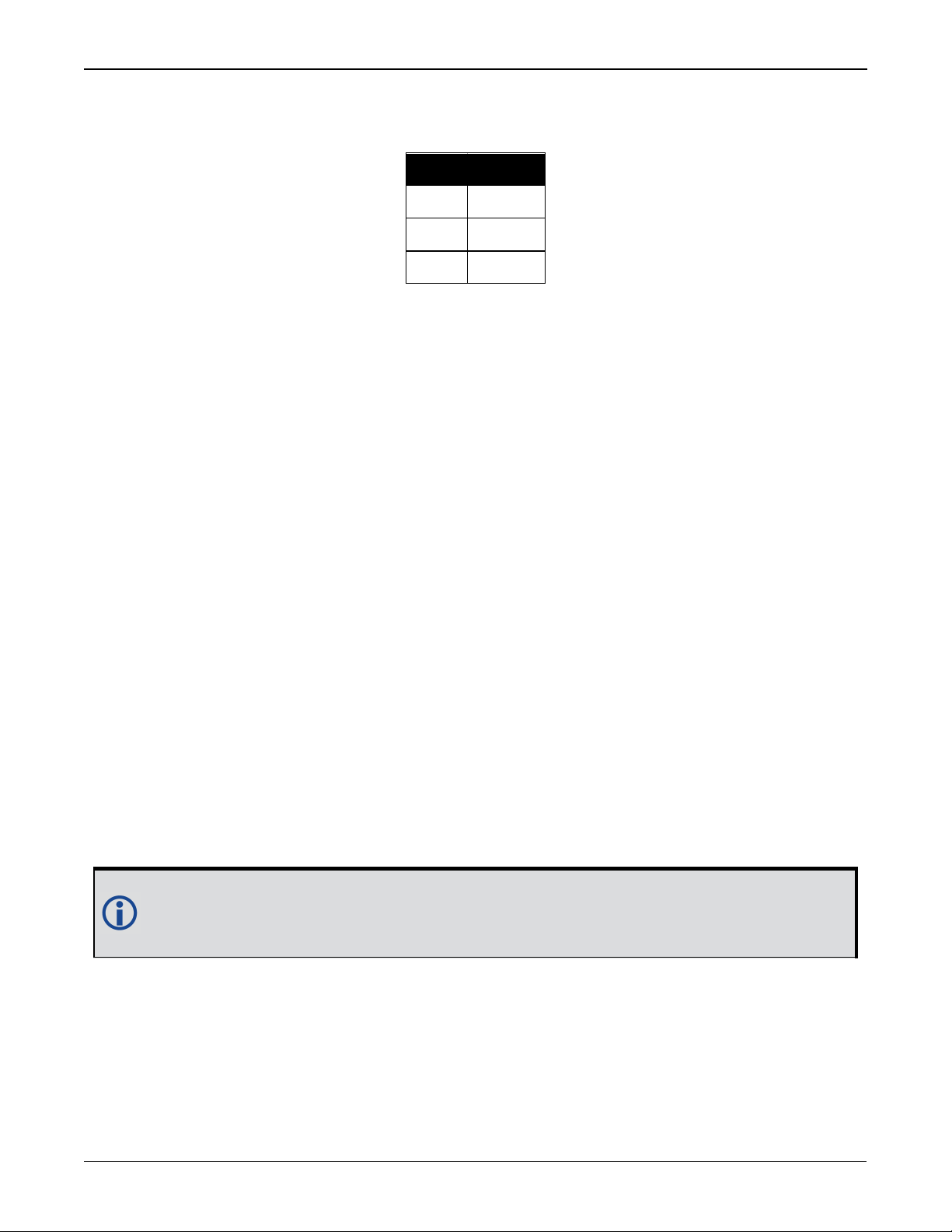
Table 1: Hardware Options
Tradename Description
SMART2 SMART2
SMART2-B SMART2 with Bluetooth
SMART2-TB
SMART2 with Bluetooth and
Terrain Compensation
Contact NovAtel Sales at www.novatel.com/where-to-buy/contact-us for information regarding
available models, upgrading a model to increase feature/functionality or go to www.nova-
tel.com/products/smart-antennas/smart2. Refer to the chapter Firmware Updates and Model
Upgrades on page52 for details.
SMART2 Installation and Operation Manual 1 11
Chapter 1 SMART2 Overview
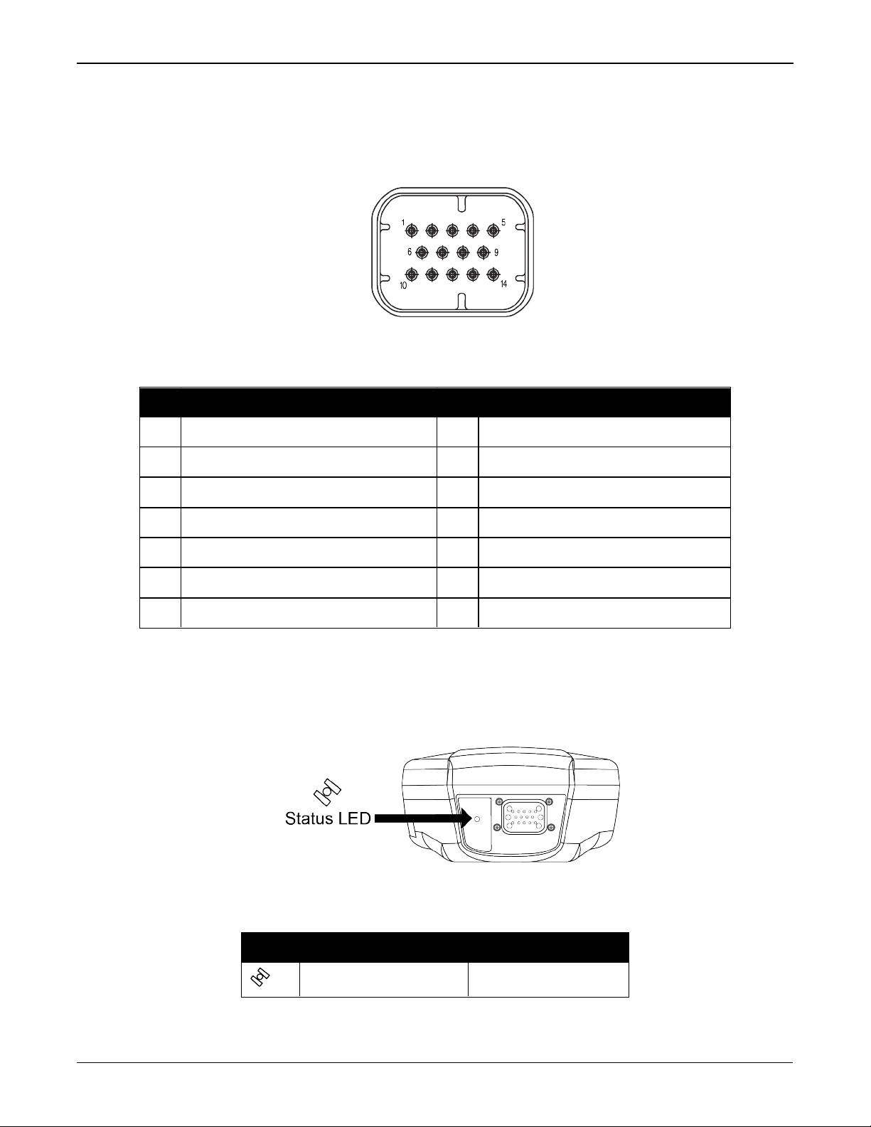
1.2 SMART2 Connector Overview
All SMART2 models use the same connector for power and communication. Refer to Table 2:
SMART2 Connector Pin-out below for pin outs.
Figure 1: SMART2 Interface Connector
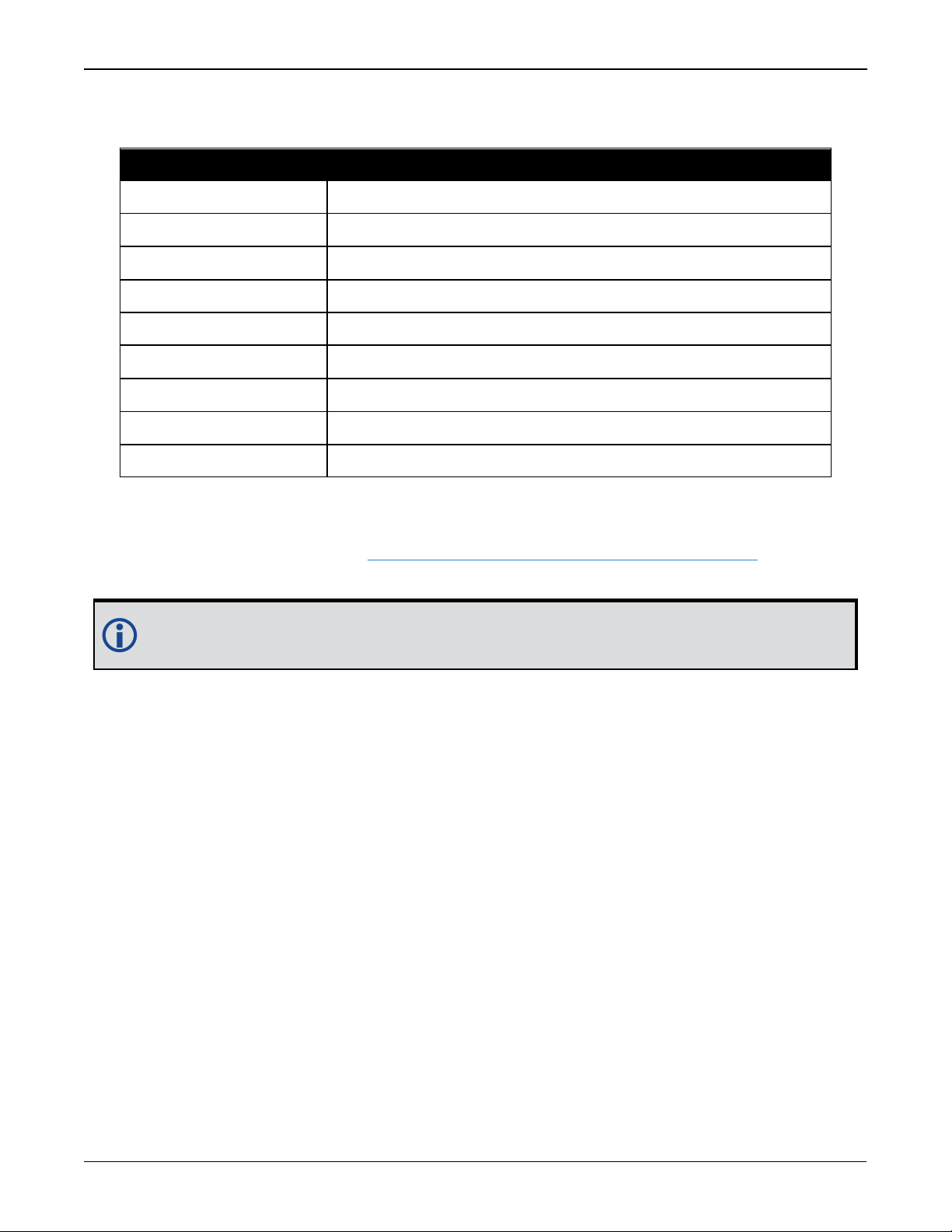
Table 2: SMART2 Connector Pin-out
Pin Use Pin Use
1 COM1 TxD 8 COM3 TxD
2 COM1 RxD 9 Power Negative/Return
3 COM2 TxD 10 ER_OUT (Emulated Radar Output)
4 COM2 RxD 11 MKI (Mark Input)
5 Signal Ground (COM/MKI/PPS/ER) 12 PPS(Pulse Per Second)Output
6 CAN+ 13 COM3 RxD
7 CAN- 14 Power Positive/Source
1.3 SMART2 LED
The SMART2 has a single LED to indicate status.
Figure 2: SMART2 Status LED
Table 3: SMART2 Status Indicator
Label Description Model
Status (Power/GNSS) All hardware options
SMART2 Installation and Operation Manual 1 12
Chapter 1 SMART2 Overview
State Description
Green Solid Precise solution good (RTK/PPP, Fixed or RTK/PPP+INS)
Green Slow Flash (1 Hz) Precise solution converging
Yellow Solid Basic solution (Single Point/SBAS/DGPS)
YellowSlowFlash (1 Hz) Tracking satellites and calculating initial position solution
Yellow Fast Flash (3 Hz) Initialized and ready for communication
Red Solid (Initial) Power On/Reset (for about 10 seconds after power-on or reset)
Red Solid (Continuous) Receiver system error, if indicator persists after 30 seconds
Red Slow Flash (1 Hz) Position quality warning (unreliable/high error)
Red Fast Flash (3 Hz) Position unavailable (unusable)
Table 4: SMART2 Status LED
1.4 Related Documents and Information
After the receiver is set up, the Agriculture Commands and Logs Reference Manual becomes the
primary source for command and log information.
Each receiver has a specific set of features, so some commands and logs may not be supported by your model.
This manual does not cover receiver service and repair. Contact a local NovAtel dealer for service or repair inquiries (refer to Customer Support on page9 for contact details).
SMART2 Installation and Operation Manual 1 13
Chapter 2 SMART2 Installation
When the appropriate equipment is selected, complete the following steps to set up and begin
using the SMART2.
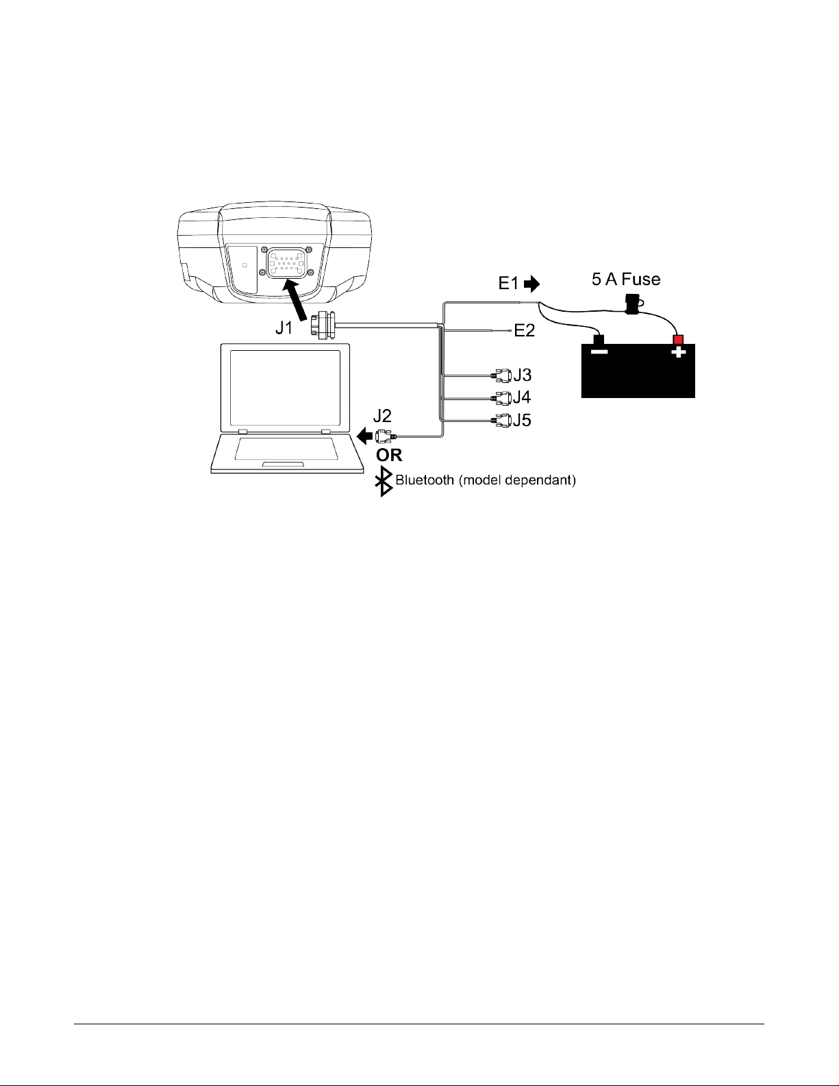
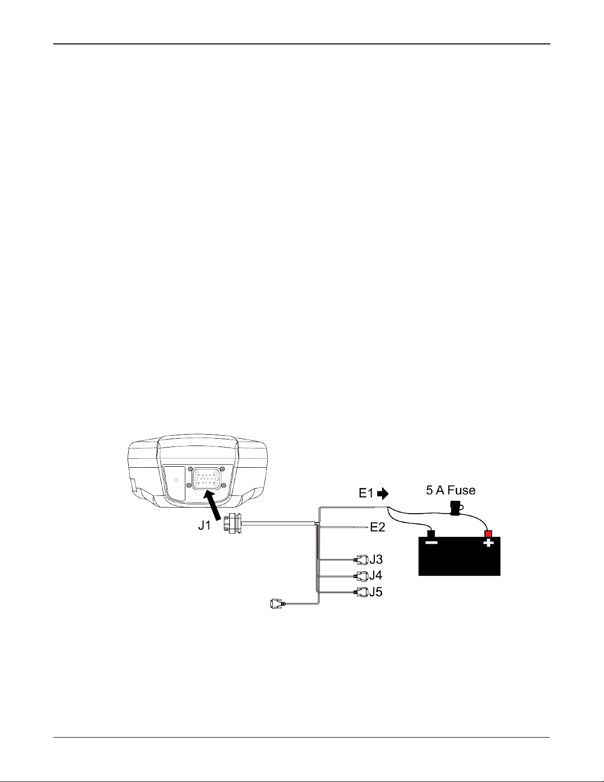
Figure 3: SMART2 Installation
1.
Mount the SMART2 receiver. Refer to Mounting and Orientating the SMART2 on the next page
for mounting details.
2.
Connect the NovAtel interface cable, or custom wiring harness, to the COM and Power port
on the back of the SMART2 (J1). Refer to SMART2 Connector Overview on page12 for details
of the connector. Refer to SMARTAntennas Interface Cable (Optional Accessory) on page73
for cable details.
3.
Connect other GNSS system components using the output lines.
4.
Connect the SMART2 to other GNSS system components, such as a computer or data terminal, using the communication ports.
See Connect the SMART2 to Data Communication Equipment on page16.
5.
Connect the power leads on the interface cable to the power supply.
Ensure a 5 A slow blow fuse is incorporated in the power wiring. Refer to SMARTAntennas
Interface Cable (Optional Accessory) on page73 and SMARTAntenna Additional Equipment
Required on page19 for fuse recommendations.
See Connect Power to the SMART2 on page18 and Power Supply Requirements for
SMARTAntennas below for details.
Refer to SMART2 LED on page12 for details of SMART2 LED states.
2.1 Power Supply Requirements for SMARTAntennas
SMARTAntennas require a power supply that provides:
l
a voltage in the range of +7 to +30 VDC, current consumption 500 mA
l
at least 15 W of power (SMART2 typical use: 2.5 W)
See Table 16: SMART2 Power Requirements on page70 for more power supply specifications.
SMART2 Installation and Operation Manual 1 14
Chapter 2 SMART2 Installation
SMARTAntennas have an internal power module that:
l
filters and regulates the supply voltage
l
protects against over-voltage, over-current and high-temperature conditions
l
provides automatic reset circuit protection
If the voltage supplied is below the minimum specification, the receiver suspends
operation. If the voltage supplied is above the maximum specification, the receiver
may be permanently damaged, voiding the warranty.
The supply must be capable of providing enough current to operate the
SMARTAntenna, including the initial inrush transient. The supply must also be
current limited to 5 A with an external fuse.
The amount of power required depends on the number of constellations and signals
tracked, and the features enabled.
Refer to SMARTAntennas Interface Cable (Optional Accessory) on page73 for details about the
power cable.
2.2 Mounting and Orientating the SMART2
2.2.1 Mounting Plate
Two mounting plates are available to facilitate mounting the receiver:
l
a surface mounting plate
l
a pole mounting plate
Refer to SMART2 Mechanical Specifications on page67 for mounting plate and pole mounting
dimensions.
Mounting the SMART2
Mount the SMART2 on a secure, stable structure capable of safe operation in the specific environment.
When installing on a vehicle, mount the SMART2 on the vehicle roof, ideally close to the pivot
point of the vehicle. The SMART2 must be mounted with the connector facing the rear of the
vehicle.
If installing in a stationary location, mount the SMART2 in a location that has a clear view of the
sky so that each satellite above the horizon can be tracked without obstruction.
SMART2 Installation and Operation Manual 1 15
Chapter 2 SMART2 Installation
The SMART2 must be rigidly secured to the vehicle to avoid errors caused by vibration
and motion.
Surface Mounting
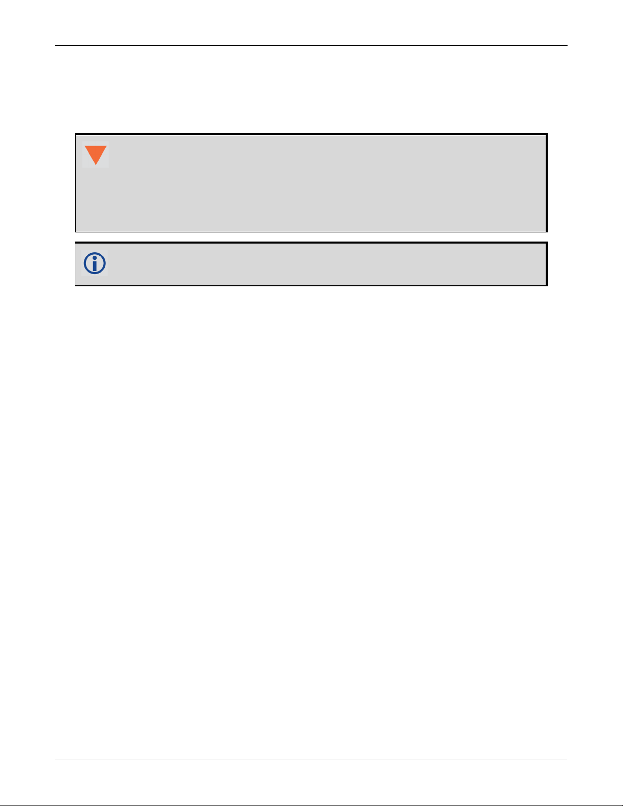
Figure 4: Orienting SMART2
To install the mounting plate, use the adhesive tape or the mounting holes at each corner of the
plate.
Pole Mounting
To install the pole mounting plate:
1.
Use four M4 screws to connect the mounting plate to the SMART2.
The optimal screw penetration into the SMART2 mounting holes is 6 mm (±1
mm) deep. When selecting screws for mounting the SMART2, ensure the screw
penetration does not exceed this specification. Using excessively long screws
can damage the SMART2 enclosure.
2.
Screw the mounting place onto a mount, such as a range pole, tribrach or tripod, with a 1" x
14 thread screw. A 5/8" to 1" bushing adapter is available (NovAtel part number 12023275).
2.3 Connect the SMART2 to Data Communication Equipment
The SMART2 can communicate with other devices in the system, such as a computer's serial or
Bluetooth port. The SMART2 also has a CAN bus port for communication with other CAN bus compatible devices.
2.3.1 Serial Ports
The SMART2 has three serial ports: COM1, COM2 and COM3. These ports are available on the 14pin Tyco Ampseal connector. Refer to SMART2 Connector Overview on page12 for the pin out of
this connector.
SMART2 Installation and Operation Manual 1 16
Chapter 2 SMART2 Installation
Table 5:
SMART2 Serial
Port Protocol
Port RS-232
COM1 Yes
COM2 Yes
COM3 Yes
Use the SERIALCONFIG command to configure the receiver’s asynchronous serial port com-
munications drivers.
Port settings (bit rate and parity, for example) are software configurable. See Communications
with the Receiver on page21 for information about configuring the serial ports. Also see
SMART2 Data Communication Specifications on page71 for the serial port specifications.
To connect to a serial port:
1.
Connect the SMART2 Interface cable (PN: 01019944), or a custom made cable, to the 14-pin
Tyco Ampseal connector.
For information about the SMART2 interface cable refer to Connect I/OSignals to a
SMARTAntenna on the next page.
2.
Connect the appropriate DB9 connector (COM1, COM2 or COM3) to the serial port on the computer or other data communication device.
2.3.2 CAN Bus Port
The SMART2 has a CAN Bus port available on the 14-Pin interface connector.
To connect to the CANBus port:
1.
Connect the SMART2 optional accessory cable or a custom made cable, to the main 14-Pin
interface connector.
For information about the SMART2 interface cable, see SMARTAntennas Interface Cable
(Optional Accessory) on page73. This section also has the connector pin out and connector
recommendations for making a custom cable.
2.
Connect the CAN to the CANBus (J5) of the SMART2 interface cable, see SMARTAntennas
Interface Cable (Optional Accessory) on page73.
The SMART2 CAN bus port is unterminated. If the SMART2 is at the end of the bus, then
the connecting cable must have 120 ohms integrated into the cable between CAN1+ and
CAN1- in close proximity to the main 14-Pin interface connector.
2.3.3 Bluetooth
Bluetooth is a wireless radio communication standard designed for use over short ranges (within
10 m). SMART2 receivers equipped with the Bluetooth hardware option support the Bluetooth
Classic SPP to provide a Bluetooth virtual serial port: COM6.
SMART2 Installation and Operation Manual 1 17
Chapter 2 SMART2 Installation
2.4 Connect I/OSignals to a SMARTAntenna
The SMARTAntennas has several outputs, also referred to as strobes, that provide status and
synchronization signals.
l
Pulse Per Second (PPS) output (E2 on SMARTAntenna Interface cable)
l
Emulated Radar Output (E2 on SMARTAntenna Interface cable)
l
Event Mark Input (MKI) (E2 on SMARTAntenna Interface cable)
To access the I/O signals, connect the interface cable or a custom made cable, to the main 14Pin interface connector. Refer to SMARTAntennas Interface Cable (Optional Accessory) on
page73 for connector pin out and other details.
2.5 Connect Power to the SMART2
To connect power to the SMART2:
1.
Connect the SMART2 Interface Cable (01019944) to the 14-Pin connector on the back of the
SMART2. See SMARTAntennas Interface Cable (Optional Accessory) on page73 for inform-
ation about this cable.
2.
Connect the BATT+ and BATT- bare wires of the interface cable to a 7 to 30 VDC power supply.
For details about the power supply required, see Power Supply Requirements for
SMARTAntennas on page14.
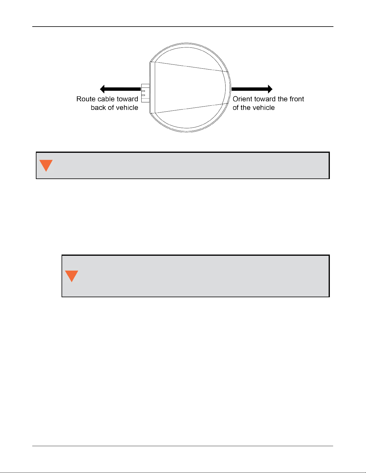
2.5.1 Fuse for the Power Supply
Install a user supplied 5 A slow blow fuse in the positive line of the connection to the power
source to protect the power supply wiring and your warranty.
Figure 5: Power Supply Fuse
Refer to SMARTAntenna Additional Equipment Required on the next page for fuse recom-
mendations.
SMART2 Installation and Operation Manual 1 18
Chapter 2 SMART2 Installation
2.6 Check that the SMARTAntenna is Working
After the SMARTAntenna is installed and powered up, use the following procedure to ensure the
receiver is operating.
1.
Check that the Status LED has changed from red to yellow or green.
The Status LED may briefly flash as Red before moving quickly to the Fast Flash Yellow.
See SMART2 LED on page12 for the LED location.
2.
Send the following command:
LOG VERSION
The VERSION log is returned.
[COM1]<VERSION COM1 0 83.0 FINESTEERING 2061 167959.862 1a04c000 3681
15699
<8
<GPSCARD "DSNLNNTMNT0G" "BMWR19050037L" "OEM2500-1.00"
"OA7CR0602RN0000" "OM7BR0100RBG000" "2019/Jun/28" "09:09:16"
<EMBEDDED_AUTH "GSNNNNNNN" "?MWR?????????" "NO_HW_VER" "NO_EXPIRY_
DATE" "" "2019/Jun/28" "09:09:35"
<APPLICATION "" "" "" "ES2AR0602RN0000" "" "2019/Jun/28" "09:09:43"
<DEFAULT_CONFIG "" "" "" "ES2CR0602RN0000" "" "2019/Jun/28"
"09:09:58"
<PACKAGE "" "" "" "ES2PR0602RN0000" "" "2019/Jun/28" "09:09:49"
<ENCLOSURE "SMART2-TB" "NMVK19060013V" "" "" "" "" ""
<BLUETOOTH "" "0081F91AFBBF" "BT121" "BT1210100RN0000" "1.2.0-208"
"2019/05/09" "15:16:47"
<IMUCARD "IAM 20680" "" "" "" "" "" ""
The Log version output will vary depending on SMARTAntenna hardware option.
3.
Check that the Time Status is FINESTEERING which represents that time is fine set and
being steered.
4.
Check the Receiver Status word (1a04c000 in this example). If the lowest bit (bit 0) is set,
the receiver has errors.
For information about the other digits in Receiver Status word, refer to the RXSTATUS
log.
2.7 SMARTAntenna Additional Equipment Required
In order for a SMARTAntenna to perform optimally, the following additional equipment is
required:
l
A computer (user supplied)
l
A cable harness for communicating with and powering the SMARTAntenna (NovAtel
SMARTAntennas Interface Cable (Optional Accessory) on page73 is available with four DB-9
connectors, six bare cables and a SMARTAntenna connector)
SMART2 Installation and Operation Manual 1 19
Chapter 2 SMART2 Installation
l
A fused +7 to +30 VDC power supply (user supplied)
Refer to Power Supply Requirements for SMARTAntennas on page14 for details.
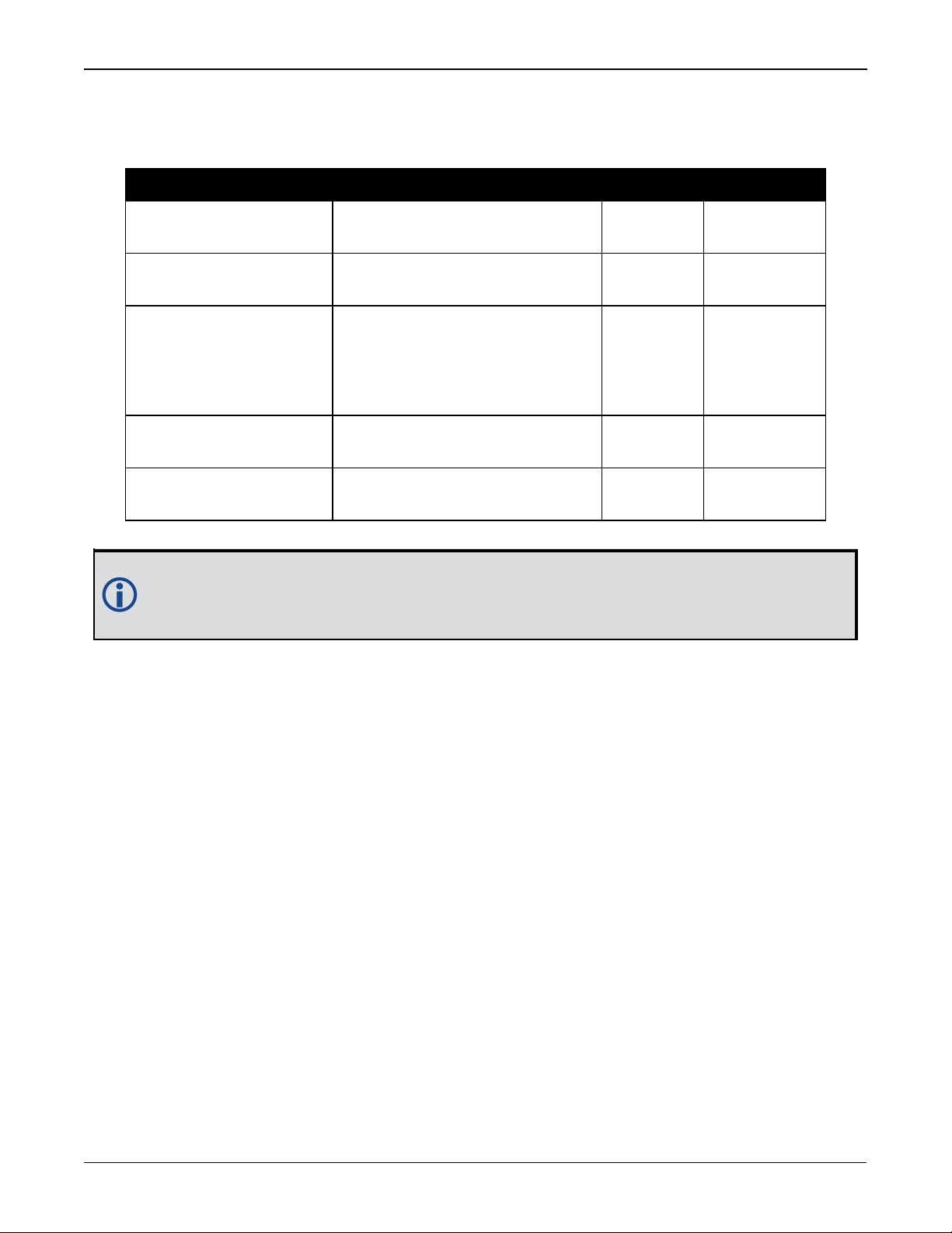
Table 6: SMART Antenna Recommended Fuse and Fuse Holders
Fuse Recommended Fuse/Fuse Holder
12 V System Fuse
(standard size blade)
12 V System Fuse
(mini size blade)
ATO Silver Blade Fuse 5 A (32 V)
or equivalent
Mini Blade Fuse 5 A (32 V)
or equivalent
Littelfuse 0287005
Littelfuse 0297005
24 V System Fuse
High Reliability,
Harsh Environment
FKS ATO Blade Fuse 5A (80 V)
or equivalent
Littelfuse 166.7000.450
(standard size blade)
Inline Fuse Holder,
(for standard size blade)
Inline Fuse Holder,
(for mini size blade)
Waterproof ATO Fuse Holder Littelfuse FHAC0001
Waterproof Mini Fuse Holder Littelfuse 0FHM0001
The Recommended Fuse and Fuse Holders table details the part numbers for recommended fuses and fuse holders. These numbers are provided for information only and
are not available from NovAtel as separate parts.
SMART2 Installation and Operation Manual 1 20
SMART2 Operation
Before operating the receiver for the first time, refer to SMART2 Overview on page11 for
SMART2 installation instructions.
Refer to Communications with the Receiver below to begin configuring the SMART2 for oper-
ation.
3.1 Communications with the Receiver
Communication is established with the receiver using a data terminal or computer connected to
the receiver by a variety of methods:
l
Serial Port Communications below
l
CAN Bus Communications on the next page
l
Bluetooth® Communications on page23 (SMART2-B and SMART2-TB hardware options only)
When connected to the receiver, enter commands directly from a terminal or through terminal
emulation software on a computer. For example:
l
NovAtel Connect - NovAtel Connect is a software application used to monitor and configure
NovAtel receivers. For information about installing and using NovAtel Connect, refer to the
help file included with the application.
NovAtel Connect version 2.0 or greater is required for SMART2. Download
the latest NovAtel Connect software and documentation from
www.novatel.com/novatel-connect.
l
Any console/command line application
To maximize the application of the receiver’s capabilities, become familiar with the commands
and logs described in Agriculture Commands and Logs Reference Manual.
3.1.1 Serial Port Communications
The receiver can communicate with a computer or terminal via a serial port. For communication
to occur, both the receiver and the operator interface have to be configured properly. The
receiver’s default port settings are:
l
9600 bps
l
no parity
l
8 data bits
l
1 stop bit
l
no handshaking
l
echo off
l
break on
The data transfer rate determines how fast information is transmitted. Take for example a log
whose message byte count is 96. The default port settings allows 10 bits/byte (8 data bits + 1
stop bit + 1 framing bit). It therefore takes 960 bits per message. To get 10 messages per
second then requires 9600 bps. Also remember that even if you set the bps to 9600, the actual
SMART2 Installation and Operation Manual 1 21
SMART2 Operation
data transfer rate may be lower and depends on the number of satellites being tracked, data filters in use, and idle time. It is therefore suggested that you leave yourself a margin when choosing a data rate.
The minimum suggested baud rate for most applications is 115200 bps. If the buffer
overrun flag is present in the RXSTATUS log (refer to the Agriculture Commands and
Logs Reference Manual), log at a higher baud rate if possible.
Although the receiver can operate at data transfer rates as low as 300 bps, this is not
recommended. For example, if several data logs are active (that is, a significant amount
of information needs to be transmitted every second) but the bit rate is set too low, data
overflows the serial port buffers, causing an error condition in the receiver status that
results in lost data.
The following ports are supported and can be configured using the commands listed.
Table 7: Serial Ports Supported
Receiver Type Port Supported Configuration Command
SMART2 COM1, COM2, COM3 SERIALCONFIG
Change the COM Port Settings
To change the settings on a COM port, use the SERIALCONFIG command. For example:
l
To change the data rate of COM2 to 115200, enter:
SERIALCONFIG COM2 115200
l
To change the data rate of COM1 to 57600 and enable even parity, enter:
SERIALCONFIG COM1 57600 E
Communicating using a Remote Terminal
One method of communicating with the receiver is through a remote terminal. To communicate
with the terminal, the receiver requires only the RX, TX and GND lines be used. Ensure the terminal’s communications set up matches the receiver’s port settings.
Communicating using a Computer
A computer can emulate a remote terminal as well as provide the added flexibility of supporting
multiple command batch files and data logging storage files. Use any standard communications
software package that emulates a terminal to establish bidirectional communications with the
receiver. Examples include NovAtel Connect and PuTTY. All data is sent as raw 8-bit binary or
ASCII characters.
Refer to Communicating with the Receiver on the next page for details.
3.1.2 CAN Bus Communications
The SMART2 supports J1939 and NMEA2000 CAN protocols.
The SMART2 has one CAN port—CAN1. CAN1 port supports data rates of up to 500 kbits/s.
SMART2 Installation and Operation Manual 1 22
SMART2 Operation
Proper bus termination is required.
Refer to SMART2 CAN Bus on page36 for details instructions.
3.1.3 Bluetooth®Communications
SMART2-B and SMART2-TB receivers support the Bluetooth Serial Port Profile to provide wireless access to the receiver's internal COM6 port. Prior to connecting to this port, your device
must first be paired to the receiver.
Bluetooth support for Apple®products require that a custom application be developed.
Contact Apple for details about creating a custom application.
Pairing Bluetooth Devices on Windows 10
On a Bluetooth capable computer, perform the following steps.
1.
Using the Windows key + I keyboard shortcut, open the Windows Settings app and select
Devices.
2.
Select Bluetooth & other devices and after ensuring the Bluetooth switch is in the On pos-
ition, click Add Bluetooth or other device.
3.
In the Add a device window, select Bluetooth.
4.
Select the SMART2 receiver from the list of nearby Bluetooth devices.
5.
Once Windows 10 has completed the pairing process, check which Bluetooth Serial Port number has been assigned to the receiver by selecting Devices and Printers.
6.
Right-click on the SMART2 device and select Properties.
7.
In the Properties window, select the Services tab. Ensure the Serial port box is checked and
record the assigned COM port.
3.2 Getting Started
The receiver’s software resides in flash memory. When first powered, it undergoes a complete
self-test. If an error condition is detected during the self-test, the status word changes. This
self-test status word can be viewed in the header of any data output log. Refer to Messages in
the Agriculture Commands and Logs Reference Manual for header information. If a persistent
error occurs, contact your local NovAtel dealer. If the dealer cannot resolve the problem, contact NovAtel Customer Support directly using one of the methods listed in Customer Support on
page9.
3.2.1 Communicating with the Receiver
You can communicate with the receiver using NovAtel Connect or a terminal emulation program.
Detailed instructions for using NovAtel Connect are available from the Help system built
into NovAtel Connect.
When the receiver is first turned on, no data is transmitted from the COM ports except for the
port prompt.
SMART2 Installation and Operation Manual 1 23
 Loading...