

Novatel PwrPak7D, PwrPak7, PwrPak7-E1, PwrPak7D-E1 Quick Start Manual
1
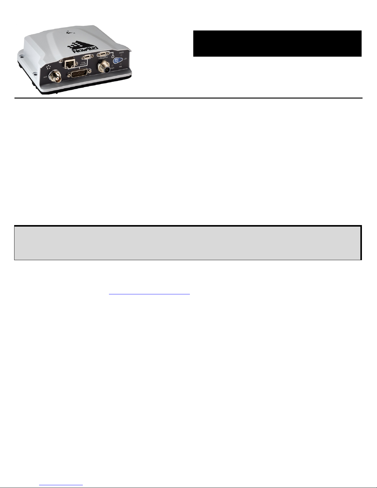
PwrPak7® Family
GM-14915152 Rev 6 July 2018
QUICK START GUIDE
This guide provides the basic information needed to set up and use a NovAtel® PwrPak7. The PwrPak7 is
a compact enclosure that delivers scalable positioning performance and contains internal storage.
There are several variants of the PwrPak7 to meet a range of GNSS applications:
USER DOCUMENTATION
For detailed information on the installation, operation, logs and commands for the PwrPak7, refer to the
OEM7 User Documentation (docs.novatel.com/OEM7
).
BOX CONTENTS
The following is provided with the PwrPak7:
• Power cable (01019764)
• PwrPak7 DB26 to DB9 COM1 cable (01019765)
• USB A to USB micro B cable (60723175)
ADDITIONAL EQUIPMENT REQUIRED
The additional equipment listed below is required for a typical setup.
• A 9-36 VDC, fuse protected power supply capable of at least 15 W
• A quality GNSS antenna, such as NovAtel’s VEXXIS
®
GNSS-500 or GNSS-800 series antennas
• An antenna cable with a TNC male connector at the receiver end such as NovAtel’s GPS-C016 model
(PwrPak7 or PwrPak7-E1), or
Two antenna cables with an SMA male connector at the receiver end such as NovAtel’s 2.5 m SMA to
TNC cable (60723177) or 5 m SMA to TNC cable (60723178) (PwrPak7D or PwrPak7D-E1)
• Four M5 or #10 size screws for mounting
PwrPak7 The PwrPak7 provides a high precision position, velocity and time (PVT) solution.
PwrPak7D The PwrPak7D is a dual antenna enclosure that provides a high precision PVT and ALIGN
®
heading solution.
PwrPak7-E1 The PwrPak7-E1 combines a GNSS receiver and an Epson EG320N IMU in a single
enclosure to provide an easy to deploy SPAN
®
GNSS+INS system.
PwrPak7D-E1 The PwrPak7D-E1 combines a dual antenna GNSS receiver and an Epson EG320N IMU
in a single enclosure to provide an easy to deploy SPAN GNSS+INS and ALIGN system.
In this document, the term PwrPak7 is used to represent all variants of the PwrPak7 enclosure
(PwrPak7, PwrPak7D, PwrPak7-E1 and PwrPak7D-E1). When a section applies to a specific
variant of the PwrPak7 enclosure, the applicable receiver is identified (e.g. PwrPak7-E1 only).
2
• A computer/tablet/smartphone with Wi-Fi and a web browser and/or a computer with an RS-232 DB-9,
Ethernet or USB port
• A Micro A to USB stick adapter, such as Tensility 10-00649 or equivalent, if you want to connect a
USB stick to the PwrPak7 TRANSFER port.
OPTIONAL ACCESSORIES
The following optional accessories are available from NovAtel:
• PwrPak7 All I/O with SPAN cable (01020004)
Provides connections for all of the signals available on the PwrPak7 COM port, including connections
for an external IMU.
• PwrPak7 I/O Extension cable (01020005)
An accessory cable for the PwrPak7 All I/O with SPAN cable that breaks out the I/O signals on the
DB15 connector to individual leads.
• Optional external SPAN compatible IMU
www.novatel.com/products/span-gnss-inertial-systems/span-imus
• PwrPak7 IMU cable (01019767)
Provides connection from the COM1 serial port on the PwrPak7 to an IMU Enclosure (IMU-HG1900,
IMU-ENC-LN200, IMU-ISA-100C or IMU-µIMU-IC) (DB26 to M12 5-pin).
For more information about these accessories refer to the OEM7 User Documentation (docs.novatel.com/
OEM7).
GETTING TO KNOW THE PWRPAK7
Refer to the OEM7 User Documentation (docs.novatel.com/OEM7) for details on all PwrPak7 connectors,
labeling and LEDs as well as detailed installation and operation instructions and information regarding
PwrPak7 logs and commands.
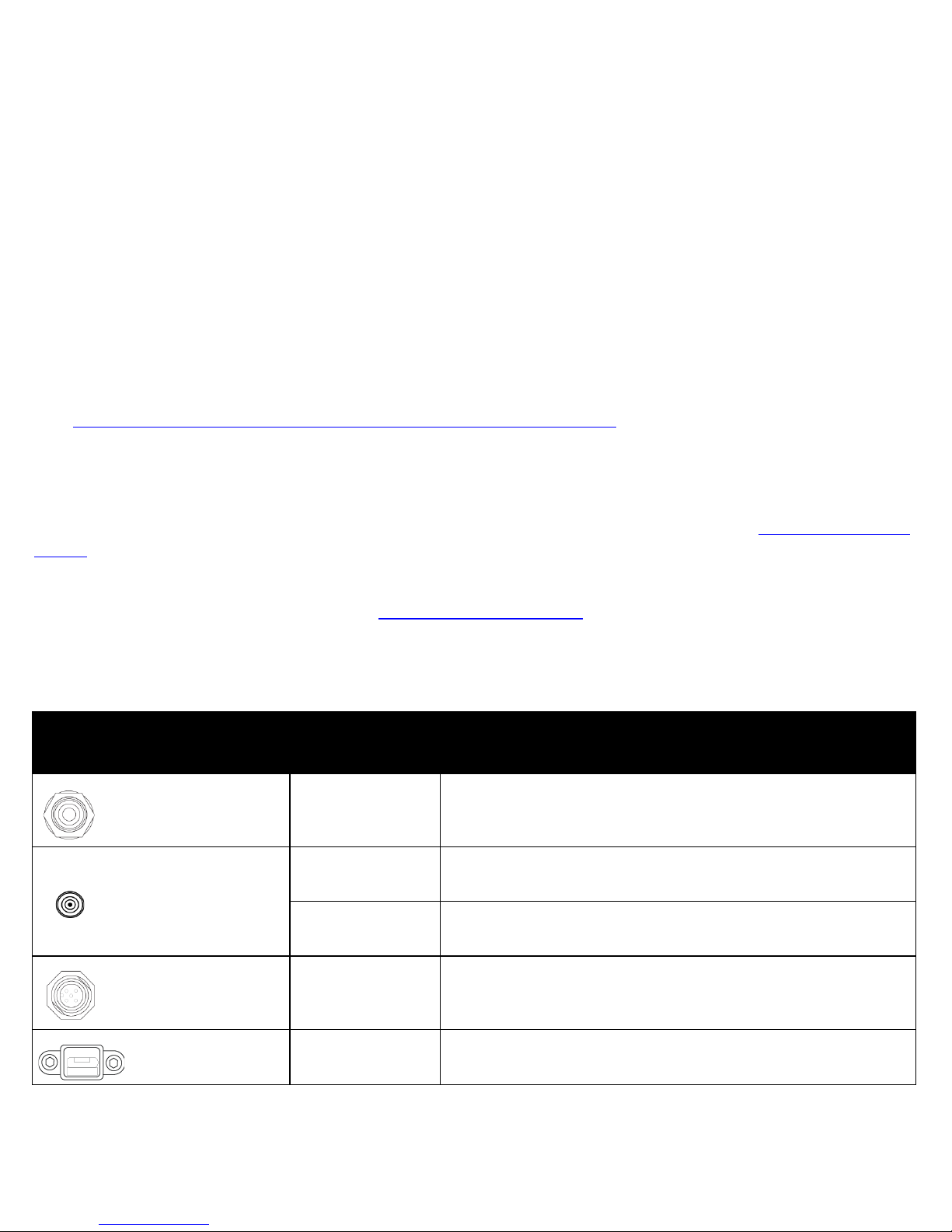
Table 1: PwrPak7 - Connector Definitions
Connector Type
Connector
Label
Description
GNSS Antenna
ANT
TNC connector for the GNSS antenna
(PwrPak7 and PwrPak7-E1)
GNSS Antenna
ANT1
SMA connector for the primary GNSS antenna
(PwrPak7D and PwrPak7D-E1)
ANT2
SMA connector for the secondary GNSS antenna
(PwrPak7D and PwrPak7D-E1)
Power
PWR SAL M12, 5-pin Male connector
USB
TRANSFER USB 2.0 Micro A/B data transfer port
3
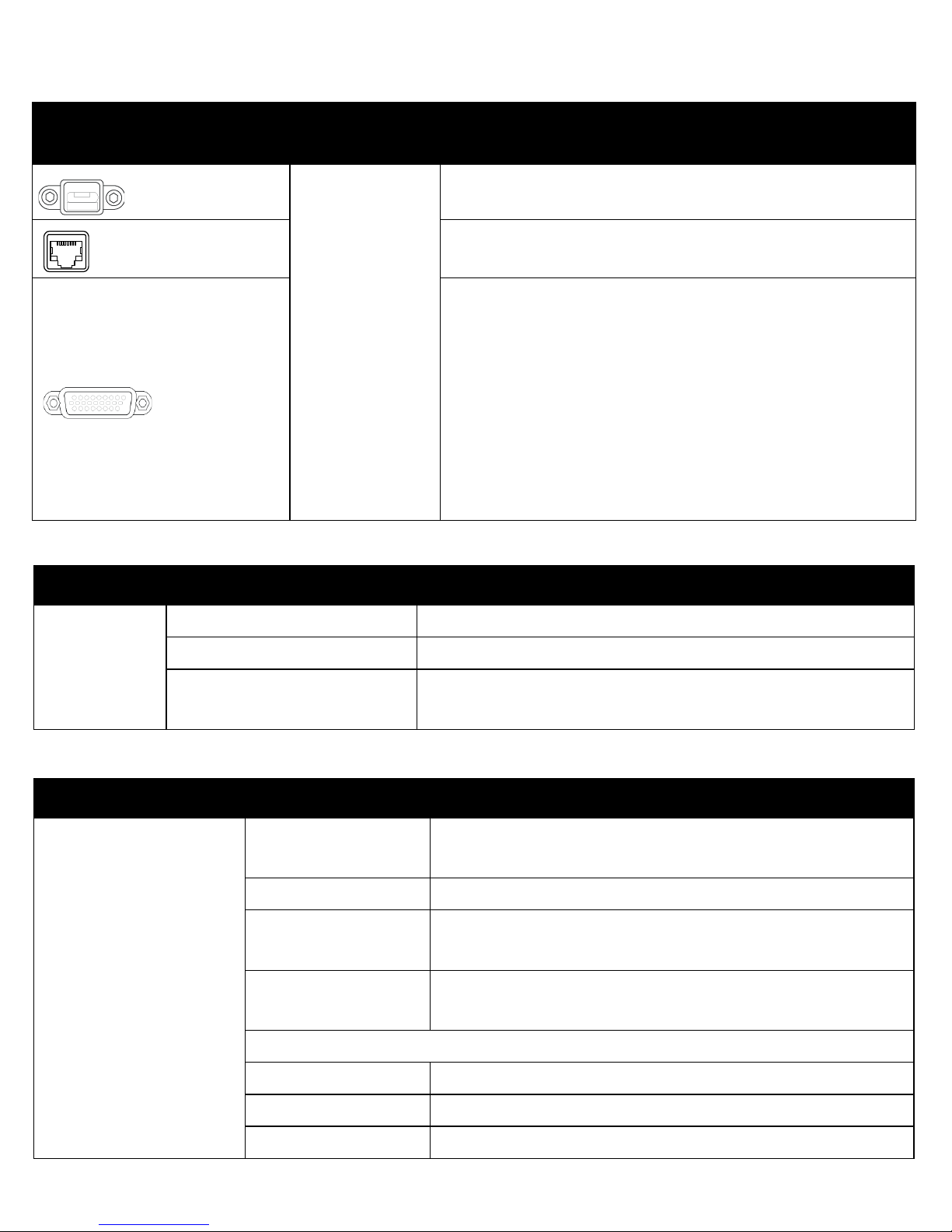
USB
COM PORTS
USB 2.0 Micro A/B virtual COM port
Ethernet
Ethernet RJ45 connector
DSUB HD26
3 Event inputs (LVCMOS)
3 Event outputs (LVCMOS)
1 Pulse Per second output (LVCMOS)
1 CAN
3 Serial ports:
• COM1 RS-232/RS-422 user selectable
• COM2 RS-232/RS-422 user selectable
• COM3 RS-232
Wheel Sensor RS-422 quadrature input
Table 2: Power LED Description
LED Label LED State Description
PWR
Green solid Operational mode
Yellow solid In process of booting
Red solid
Error, for example, invalid receiver AUTH code
Firmware/Web UI update in progress
Table 3: GNSS LED Description
LED Label LED State Description
GNSS
indicates the position
status of the receiver
Green solid
PPP Solution
User Accuracy Level (UAL) Operational (STEADYLINE)
Green slow blink RTK integer ambiguity
Green fast blink
Single point or SBAS position
UAL Warning
Yellow solid
No solution
UAL Out of Bounds
If the PwrPak7 is configured as a Base
Green solid Fixed position
Yellow solid Pending fixed position
Yellow blink Invalid fix
Table 1: PwrPak7 - Connector Definitions
Connector Type
Connector
Label
Description

4
Table 4: INS LED Description
LED Label LED State Description
INS
indicates the INS
status of the receiver
(PwrPak7-E1,
PwrPak7D-E1, or
PwrPak7 / PwrPak7D
with an external IMU)
Off INS inactive
Green solid INS solution good
Green slow blink INS alignment complete
Green fast blink INS solution free
Green/Yellow alternating blink High variance
Yellow solid INS aligning/determining orientation
Red solid Error
Table 5: USB TRANSFER LED Description
LED State Description
Green solid
Stick plugged in, mounted and idle (lots of available memory)
Transfer port connected to a computer
Green slow blink Logging to stick (lots of available memory)
Green fast blink Transferring files to stick (lots of available memory)
Green/Yellow alternating slow blink Logging to stick (low available memory)
Green/Yellow alternating fast blink Transferring files to stick (low memory)
Yellow solid Stick plugged in, mounted and idle (low available memory)
Yellow fast blink Stick mounting or unmounting/busy
Red solid Stick plugged and mounted, but memory full
Red fast blink for 3 seconds Push button error or stick mount error
Off No connection to the TRANSFER port or stick is unmounted
Table 6: LOG LED and Button Description
LOG
Button
with LED
LED State Description
Logging
Green slow blink Logging to Internal (lots of memory available)
Green solid Internal logging stopped (lots of memory available)
Green/Yellow alternating blink Logging to Internal (low memory)
Yellow solid Internal logging stopped (low memory)
Yellow fast blink Memory is mounting or unmounting/busy
Red fast blink for 3 seconds Push button error
Off PwrPak7 is connected to a computer as a mounted device
 Loading...