

Novatel PwrPak7 Installation And Operation Manual

PwrPak7
Installation and Operation
User Manual
OM-20000173 v1A November 2017

PwrPak7 Installation and Operation User Manual
PwrPak7 Installation and Operation User Manual
Publication Number: OM-20000173
Revision Level: v1A
Revision Date: November 2017
Firmware Version: PP7 01.00 / EP7PR0100RN0000
To download the latest firmware and/or software visit: www.novatel.com/support/firmware-
downloads.
Warranty
NovAtel Inc. warrants that its GNSS products are free from defects in materials and workmanship, subject to the conditions set forth on our web site: www.nova-
tel.com/products/warranty/ and for the following time periods:
OEM7®Receivers One (1) Year
GNSS Antenna Series One (1) Year
Cables and Accessories Ninety (90) Days
Software Warranty One (1) Year
Return Instructions
To return products, refer to the instructions found at: www.novatel.com/warranty-return.
Proprietary Notice
Information in this document is subject to change without notice and does not represent a commitment on the part of NovAtel Inc. The software described in this document is furnished under
a licence agreement or non-disclosure agreement. The software may be used or copied only in
accordance with the terms of the agreement. It is against the law to copy the software on any
medium except as specifically allowed in the license or non-disclosure agreement.
The information contained within this manual is believed to be true and correct at the time of
publication.
OEM7, SPAN, ALIGN, GLIDE, STEADYLINE, VEXXIS and NovAtel are registered trademarks of
NovAtel Inc.
OEM719, OEM729, OEM7700, OEM7720, PwrPak7, NovAtel CORRECT, RTK ASSIST and NovAtel
Connect are trademarks of NovAtel Inc.
All other brand names are trademarks of their respective holders.
© Copyright 2017 NovAtel Inc. All rights reserved.
Unpublished rights reserved under International copyright laws.
PwrPak7 Installation and Operation User Manual v1A 2

PwrPak7 Installation and Operation User Manual
Table of Contents
PwrPak7 Installation and Operation User Manual
PwrPak7 Installation and Operation User Manual 2
Warranty 2
Return Instructions 2
Proprietary Notice 2
Figures
Tables
PwrPak7 Notices
FCC 9
Innovation, Science and Economic Development (ISED) Canada 9
Wi-Fi 10
European Union (EU) 10
PwrPak7 Wi-Fi 10
Radio Information 10
Ethernet Port 10
WEEE Notice 10
RoHS 11
REACH 11
Lightning Protection Installation and Grounding Procedure 12
What is the hazard? 12
Hazard Impact 12
Actions to Mitigate Lightning Hazards 12
Conventions 14
Customer Support
NovAtel Knowledge Base 15
Before Contacting Customer Support 15
Contact Information 15
Chapter 1 PwrPak7 and PwrPak7-E1 Overview
1.1 PwrPak7 Connectors 18
1.2 PwrPak7 LEDs 19
1.3 Related Documents and Information 22
Chapter 2 PwrPak7 Installation
2.1 Shipping Box 23
2.2 Additional Equipment Required 23
2.3 Optional Accessories 23
2.4 PwrPak7 Cables 24
2.5 Selecting a GNSS Antenna 24
2.6 Choosing a Coaxial Cable 25
2.7 Power Supply Requirements for the PwrPak7 25
2.8 PwrPak7 Installation Overview 26
2.9 Mounting the GNSS Antenna 28
2.9.1 Antenna LNA Power 28
2.10 Mount the PwrPak7 28
PwrPak7 Installation and Operation User Manual v1A 3

PwrPak7 Installation and Operation User Manual
2.11 Mount the PwrPak7-E1 29
2.12 Connect the PwrPak7 to Data Communication Equipment 30
2.12.1 Serial Ports 30
2.12.2 USB Ports 31
2.12.3 Wi-Fi 31
2.12.4 Ethernet Port 32
2.12.5 CAN Bus Port 32
2.13 Connect I/O Signals to the PwrPak7 32
2.14 Connect Power to the PwrPak7 32
2.14.1 Fuse for the Power Supply 33
2.14.2 Vehicle Installation 34
2.14.3 Seamless Battery Swap 34
2.15 Check that the PwrPak7 is Operating 35
Chapter 3 OEM7 Receiver Operation
3.1 Communications with the Receiver 37
3.1.1 Wi-Fi Communications 38
3.1.2 USB Communications 38
3.1.3 Serial Port Communications 39
Change the COM Port Settings 40
Configure a COM Port to Use RS-232 or RS-422 40
3.1.4 Ethernet Communications 40
3.1.5 CAN Bus Communications 41
3.1.6 ICOM Communications 41
3.2 Getting Started 42
3.2.1 Communicating with the Receiver 42
3.3 Transmitting and Receiving Corrections 43
3.3.1 Defining Antenna and Base Antenna 45
3.3.2 Base Station Configuration 45
3.3.3 Rover Station Configuration 46
3.3.4 Configuration Notes 46
3.4 ALIGN Heading Master and Remote Configurations 47
3.4.1 Automatic Set Up for Direct-Wire Connection between Master and Rover via
COM2 47
3.4.2 Manual Set Up via COM2 47
3.5 GLIDE 48
3.5.1 Dual-Frequency GLIDE 48
3.5.2 PDP and GLIDE Configurations 48
3.6 STEADYLINE 49
3.6.1 Maintain 49
3.6.2 Transition 50
3.6.3 Prefer Accuracy 50
3.6.4 UAL 51
3.7 Enabling SBAS Positioning 52
3.8 Enabling NovAtel CORRECT with PPP 52
3.8.1 TerraStar Subscriptions 53
3.8.2 Veripos Subscriptions 54
3.9 RTK ASSIST 54
3.10 Transferring Time Between Receivers 55
3.10.1 GPS to Receiver Time Synchronization 55
3.10.2 Time Definitions 55
3.10.3 Procedures to Transfer Time 56
3.11 Interference Toolkit 60
3.11.1 Monitoring GNSS Signals 60
PwrPak7 Installation and Operation User Manual v1A 4

PwrPak7 Installation and Operation User Manual
3.11.2 Monitoring Signals Using a Command Line 61
3.11.3 Monitoring Signals Using NovAtel Connect 61
3.11.4 Configure Filters 63
3.11.5 Remove Interference Signals 63
3.12 Logging and Retrieving Data Overview 66
3.12.1 Pass-Through Logging 66
3.12.2 Saving Logs to a File 66
3.12.3 Logging to Internal Memory 67
3.12.4 Logging Using the Log Button 68
3.12.5 Transferring Files from Internal Memory to a USB Stick 69
3.12.6 Access Internal Memory with a Computer 71
3.13 Additional Features and Information 72
3.13.1 Strobes 72
Chapter 4 Built-In Status Tests
4.1 Receiver Status Word 73
4.2 RXSTATUSEVENT Log 74
4.3 RXSTATUS Log 74
4.3.1 Status Word 74
4.3.2 Error Word 74
4.3.3 Status Code Arrays 75
4.3.4 Receiver Status Code 76
4.3.5 Auxiliary Status Codes 76
4.3.6 Set and Clear Mask for all Status Code Arrays 76
Chapter 5 Ethernet Configuration
5.1 Required Hardware 77
5.2 Static IP Address Configuration 77
5.2.1 Static IP Address Configuration—Receiver 78
5.2.2 Static IP Address Configuration—Windows 7 79
5.2.3 Confirming Ethernet Setup 80
5.3 Dynamic IP Address Configuration 80
5.4 Base/Rover Configuration through Ethernet Connectivity 81
5.5 Large COM Port Data Throughput 83
5.6 NTRIP Configuration 83
Chapter 6 Wi-Fi Configuration
6.1 Enable the Wi-Fi Access Point 86
6.2 Disable Wi-Fi 86
6.3 Change the Wi-Fi PassKey 87
6.4 Change the Wi-Fi Channel 87
6.5 Change the Wi-Fi IPAddress 87
Chapter 7 CAN Bus
7.1 Default Configuration 90
7.2 Configuring the CAN Bus 90
7.2.1 Configuration Notes 90
7.2.2 Example of Enabling the CAN Bus 91
7.2.3 Example of Modifying the CAN Bus Parameters 91
7.2.4 Example of Detecting an Address Claim Failure and Reconfiguring 91
7.2.5 Address Claim Procedure 92
7.3 NMEA2000 Logging 92
7.3.1 Example of NMEA2000 Log Configuration 93
PwrPak7 Installation and Operation User Manual v1A 5

PwrPak7 Installation and Operation User Manual
7.3.2 Example of Custom PGN Configuration 93
7.4 Corrections Over CAN 93
7.4.1 Example for Receiving Corrections from Any Source 94
7.4.2 Example for Transmitting Corrections to 0x1C Node 94
7.5 NovAtel Messages Over CAN 94
7.6 Configuring OEM7 Receivers to Use OEM6 CAN Settings 94
7.6.1 Configuration on OEM6 95
7.6.2 Configuration on OEM7 95
Chapter 8 Troubleshooting
8.1 Examining the RXSTATUS Log 97
8.2 Examining the AUX1 Status Word 100
8.3 Safe Mode 101
8.3.1 Reset Loop Detection 101
8.3.2 Recovery Steps 101
Chapter 9 NovAtel Firmware and Software
9.1 Firmware Updates and Model Upgrades 103
9.1.1 Firmware Updates 103
9.1.2 Model Upgrades 103
9.2 Authorization Code 104
9.3 Updating or Upgrading Using the WinLoad Utility 105
9.3.1 Transferring Firmware Files 105
9.3.2 Using the WinLoad Utility 105
9.4 Updating Using SoftLoad Commands 107
9.4.1 SoftLoad Commands and Logs 107
9.4.2 Working With S-Records 108
9.4.3 Sending Firmware Data 109
9.4.4 SoftLoad Update Method 110
9.4.5 SoftLoad Errors 113
9.5 Upgrading Using the AUTH Command 113
9.5.1 Upgrade Procedure 113
APPENDIX A PwrPak7 Specifications
A.1 PwrPak7 Performance Specifications 116
A.2 PwrPak7 Mechanical Specifications 119
A.3 PwrPak7 Electrical and Environmental Specifications 121
A.4 PwrPak7 Data Communication Specifications 123
A.5 PwrPak7 Strobe Specifications 125
A.6 PwrPak7 Connectors 126
A.7 PwrPak7 Power Cable 129
A.8 PwrPak7 All I/O Cable 130
A.9 PwrPak7 COM1 Cable 132
A.10 PwrPak7 IMU Cable 133
APPENDIX B Importance of Antenna Selection
PwrPak7 Installation and Operation User Manual v1A 6

Figures
Figure 1: PwrPak7 Enclosure 18
Figure 2: PwrPak7 Connectors 18
Figure 3: PwrPak7 Status Indicators 19
Figure 4: PwrPak7 Installation Example 27
Figure 5: Fuse for PwrPak7 Power Supply 33
Figure 6: Dedicated Battery for PwrPak7 34
Figure 7: Seamless Battery Swap 34
Figure 8: Basic Receiver Enclosure Connection Interfaces (example) 37
Figure 9: Basic Differential Setup 44
Figure 10: Positioning Change Without STEADYLINE 49
Figure 11: STEADYLINE Maintain 50
Figure 12: STEADYLINE Transition 50
Figure 13: STEADYLINE Prefer Accuracy 50
Figure 14: STEADYLINE UAL- Warning Limit Example 51
Figure 15: STEADYLINE UAL - Out of Bounds Example 52
Figure 16: Transfer COARSE Time from Fine Clock to Cold Clock Receiver 57
Figure 17: Transfer FINE Time from Fine Clock to Cold Clock Receiver 58
Figure 18: Transfer FINE Time from Fine Clock to Warm Clock Receiver 59
Figure 19: 1 PPS Alignment 59
Figure 20: Location of Receiver Status Word 74
Figure 21: Reading the Bits in the Receiver Status Word 74
Figure 22: Location of Receiver Error Word 75
Figure 23: Reading the Bits in the Receiver Error Word 75
Figure 24: Status Code Arrays 76
Figure 25: Cross-Over Ethernet Cable Configuration—OEM7 Receiver 78
Figure 26: Dynamic IP Address Configuration through a DHCP Server—OEM7 Receiver 80
Figure 27: Base/Rover Ethernet Setup—OEM7 Receiver 82
Figure 28: NTRIP System 84
Figure 29: WinLoad’s Open Window 106
Figure 30: Open File in WinLoad 106
Figure 31: COM Port Setup 107
Figure 32: PwrPak7 Dimensions 119
Figure 33: PwrPak7-E1 Center of Navigation 120
Figure 34: PwrPak7 Power Cable 129
Figure 35: PwrPak7 All I/O Cable 130
Figure 36: PwrPak7 COM1 Cable 132
Figure 37: PwrPak7 IMU Cable 133
Figure 38: Plot of Good and Poor Antenna Phase Center Variation over Elevation Angle 0-
90° 135
PwrPak7 Installation and Operation User Manual v1A 7

Tables
Table 1: PwrPak7 Connectors 18
Table 2: PwrPak7 Status Indicators 20
Table 3: PWR (Power) LED 20
Table 4: GNSS LED 20
Table 5: INS LED 21
Table 6: TRANSFER LED 21
Table 7: LOG (Onboard Storage) LED 21
Table 8: PwrPak7 Cables 24
Table 9: PwrPak7 Serial Port Protocol 30
Table 10: Fuse/Holder Recommendations 12 V System 33
Table 11: Serial Ports Supported 40
Table 12: Wi-Fi Default Configuration 86
Table 13: Default NAME 90
Table 14: Troubleshooting Based on Symptoms 96
Table 15: Resolving a Receiver Error Word 98
Table 16: Resolving an Error in the Receiver Status Word 99
Table 17: Resolving an Error in the AUX1 Status Word 100
Table 18: PwrPak7 Physical Description 115
Table 19: PwrPak7 Receiver Performance 116
Table 20: PwrPak7-E1 IMU Performance 117
Table 21: PwrPak7 Environmental Specifications 121
Table 22: PwrPak7 Power Requirements 121
Table 23: PwrPak7 RF Input/LNA Power Output 121
Table 24: Data Communications Interfaces 123
Table 25: PwrPak7 Strobes Description 125
Table 26: PwrPak7 Strobe Electrical Specifications 125
Table 27: PwrPak7 Connectors 126
Table 28: 26 Pin D-SUB High Density Pin Out 127
Table 29: PwrPak7 Power Cable Pinout 129
Table 30: PwrPak7 All I/O Cable Pinout 130
Table 31: PwrPak7 COM1 Cable Pinout 132
Table 32: PwrPak7 IMU Cable Pinout 133
PwrPak7 Installation and Operation User Manual v1A 8

PwrPak7 Notices
The following notices apply to the PwrPak7 device.
Changes or modifications to this equipment, not expressly approved by NovAtel Inc.,
could void the user’s authority to operate this equipment.
FCC
This device complies with part 15 of the FCC Rules. Operation is subject to the following two conditions: (1) this device may not cause harmful interference, and (2) this device must accept any
interference received, including interference that may cause undesired operation.
PwrPak7 has been tested and found to comply with the radiated and conducted emission limits
for a Class B digital device. The Class B limits are designed to provide reasonable protection
against harmful interference in a residential installation.
The equipment listed generates, uses and can radiate radio frequency energy and, if not
installed and used in accordance with the instructions, may cause harmful interference to radio
communications. However, there is no guarantee that interference will not occur in a particular
installation. If this equipment does cause harmful interference to radio or television reception,
which can be determined by turning the equipment off and on, the user is encouraged to try to
correct the interference by one or more of the following measures:
l Re-orient or relocate the PwrPak7
l Increase the separation between the equipment and the PwrPak7
l Connect the equipment to an outlet on a circuit different from that to which the PwrPak7 is
connected
l Consult the dealer or an experienced radio/TV technician for help
To maintain compliance with the limits of a Class B digital device, you must use shielded
interface cables.
The PwrPak7 has been authorized for use in Mobile applications. At least 20 cm (8
inches) of separation between the PwrPak7 and the User must be maintained at all
times.
Innovation, Science and Economic Development (ISED) Canada
PwrPak7 Class B digital device complies with Canadian ICES-003.
PwrPak7 appareil numérique de la classe B est conforme à la norme NMB-003 du Canada.
This device complies with ISED license-exempt RSS-GEN and RSS-247. Operation is subject to
the following two conditions: (1) this device may not cause interference and (2) this device must
accept any interference, including interference that may cause undesired operation of the
device.
PwrPak7 Installation and Operation User Manual v1A 9
PwrPak7 Notices
The PwrPak7 has been authorized for use in Mobile applications. At least 20 cm (8
inches) of separation between the PwrPak7 and the User must be maintained at all
times.
Wi-Fi
PwrPak7 contains a Wi-Fi radio with the following approvals:
l FCC ID: UTU-01019715
l IC: 129A-01019715
European Union (EU)
PwrPak7 Wi-Fi
NovAtel Inc. declares that the PwrPak7 Wi-Fi transceiver is in compliance with Directive
2014/53/EU (Radio Equipment).
The full text of the EU Declaration of Conformity may be obtained from the NovAtel web site at:
www.novatel.com/products/compliance/eu-declaration-of-conformity
Radio Information
Description of Service: Wi-Fi (802.11b/g/n)
Operational Frequency: 2400 MHz to 2480 MHz
Modulation: OFDM
Rated Power: 17.5 dBm e.i.r.p
The full text of the EU Declaration of Conformity may be obtained from the NovAtel web site at:
www.novatel.com/products/compliance/eu-declaration-of-conformity
Ethernet Port
The Ethernet port is a safety extra-low voltage (SELV) circuit only and is suitable for connection within a building only. Do not connect them to telephone-network voltage (TNV)
circuits.
WEEE Notice
If you purchased your PwrPak7 product in Europe, please return it to your dealer or supplier at
the end of its life. The objectives of the European Community's environment policy are, in particular, to preserve, protect and improve the quality of the environment, protect human health
and utilise natural resources prudently and rationally. Sustainable development advocates the
reduction of wasteful consumption of natural resources and the prevention of pollution. Waste
electrical and electronic equipment (WEEE) is a regulated area. Where the generation of waste
cannot be avoided, it should be reused or recovered for its material or energy. WEEE products
may be recognized by their wheeled bin label ( ).
PwrPak7 Installation and Operation User Manual v1A 10
PwrPak7 Notices
See www.novatel.com/products/compliance/environmental-compliance for more information.
RoHS
The PwrPak7 is in conformity with Directive 2011/65/EU of the European Parliament and of the
council of 8 June 2011 on the restriction of the use of certain hazardous substances in electrical
and electronic equipment.
REACH
The PwrPak7 is compliant with Regulation (EC) No. 1907/2006 of the European Parliament and
the Council of 18 December 2006 concerning the Registration, Evaluation, Authorization and
Restriction of Chemicals (REACH). The candidate list of Substances of Very High Concern (SVHC)
published by the European Chemical Agency (ECHA) is available at: https://echa.europa.eu-
/candidate-list-table
Cables may contain DEHP (CAS Number 117-81-7) in concentrations above 0.1% w/w.
PwrPak7 Installation and Operation User Manual v1A 11
PwrPak7 Notices
Lightning Protection Installation and Grounding Procedure
What is the hazard?
A lightning strike into the ground causes an increase in the earth's potential which results in a
high voltage potential between the center conductor and shield of the coaxial cable. This high
voltage develops because the voltage surge induced onto the center conductor lags in time
behind the voltage surge induced onto the shield.
Hazard Impact
A lightning strike causes the ground potential in the area to rise to dangerous levels resulting in
harm to personnel or destruction of electronic equipment in an unprotected environment. It also
conducts a portion of the strike energy down the inner conductor of the coaxial cable to the connected equipment.
Only qualified personnel, such as electricians mandated by the governing body in the
country of installation, may install lightning protection devices.
Actions to Mitigate Lightning Hazards
1.
Do not install antennas or antenna coaxial cables outside the building during a lightning
storm.
2.
It is not possible to avoid over voltages caused by lightning, but a lightning protection device
may be used to shunt a large portion of the transient energy to the building ground, reducing
the over voltage condition as quickly as possible.
3.
Primary lightning protection must be provided by the operator/customer according to local
building codes as part of the extra building installation.
4.
To ensure compliance with clause 7 "Connection to Cable Distribution Systems" of EN 609501, Safety for Information Technology Equipment, a secondary lightning protection device
must be used for in-building equipment installations with external antennas. The following
device has been approved by NovAtel Inc.:
Polyphaser - Surge Arrestor DGXZ+36NFNF-A
If this device is not chosen as the primary lightning protection device, the device chosen
must meet the following requirements:
l
UL listed, or equivalent, in country of installation (for example, TUV, VDE and so on) for
lightning surge protection
l
The primary device must be capable of limiting an incoming surge to 10 kV
5.
The shield of the coaxial cable entering the building should be connected at a grounding plate
at the building's entrance. The lightning protection devices should have their chassis grounded to the same ground near to the building's entrance.
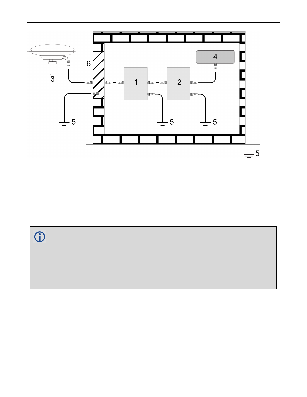
6.
The primary and secondary lightning protections should be as close to the building's entrance
as possible. Where feasible, mount onto the grounding plate itself (refer to the figure
below).
PwrPak7 Installation and Operation User Manual v1A 12
PwrPak7 Notices
Ref# Description
1 Primary lightning protection device
2 Secondary lightning protection device
3 External antenna
4 GNSS Receiver
5 To ground
6 Grounding plate or grounding point at the building’s entrance
Acceptable choices for earth grounds, for central buildings, are:
l
Grounded interior metal cold water pipe within five feet (1.5 m) of the point where
it enters the building
l
Grounded metallic service raceway
l
Grounded electrical service equipment enclosure
l
Eight-foot grounding rod driven into the ground (only if bonded to the central building ground by #6, or heavier, bonding wire)
These installation instructions are the minimum requirements for receiver and antenna installations.
Where applicable, follow the electrical codes for the country of installation. Examples of country
codes include:
l
USA National Electrical Code (NFPA 70)
l
Canada Canadian Electrical Code (CSA C22.1)
l
UK British Standards Institute (BSI 7671)
PwrPak7 Installation and Operation User Manual v1A 13
PwrPak7 Notices
Conventions
The following conventions are used in this manual:
Information that supplements or clarifies text.
A caution that actions, operation or configuration may lead to incorrect or improper use
of the hardware.
A warning that actions, operation or configuration may result in regulatory noncompliance, safety issues or equipment damage.
PwrPak7 Installation and Operation User Manual v1A 14
Customer Support
NovAtel Knowledge Base
If you have a technical issue, visit the NovAtel Support page at www.novatel.com/support.
Through the Support page, you can contact Customer Support, find papers and tutorials or down-
load current manuals and the latest firmware.
Before Contacting Customer Support
Before you contact NovAtel Customer Support about a software problem, perform the following
steps:
If logging data over an RS-232 serial cable, ensure that the configured baud rate can support the data bandwidth (see SERIALCONFIG command). NovAtel recommends a min-
imum suggested baud rate of 115200 bps.
1.
Log the following data to a file on your computer for 15 minutes:
RXSTATUSB once
RAWEPHEMB onchanged
GLORAWEPHEMB onchanged
BESTPOSB ontime 1
RANGEB ontime 1
RXCONFIGA once
VERSIONA once
For SPAN systems, add the following logs to the above list in the file created on your computer:
RAWIMUSXB onnew
INSUPDATESTATUSB onnew
INSPVAXB ontime 1
INSCONFIGA once
2.
Send the data file to NovAtel Customer Support: support@novatel.com
3.
You can also issue a FRESET command to the receiver to clear any unknown settings.
The FRESET command will erase all user settings. You should know your configuration
(by requesting the RXCONFIGA log) and be able to reconfigure the receiver before you
send the FRESET command.
If you are having a hardware problem, send a list of the troubleshooting steps taken and the results.
Contact Information
Log a support request with NovAtel Customer Support using one of the following methods:
Log a Case and Search Knowledge:
PwrPak7 Installation and Operation User Manual v1A 15

Customer Support
Website: www.novatel.com/support
Log a Case, Search Knowledge and View Your Case History: (login access required)
Web Portal: https://novatelsupport.force.com/community/login
E-mail:
support@novatel.com
Telephone:
U.S. and Canada:1-800-NOVATEL (1-800-668-2835)
International:+1-403-295-4900
PwrPak7 Installation and Operation User Manual v1A 16
Chapter 1 PwrPak7 and PwrPak7-E1 Overview
NovAtel's PwrPak7 uses the OEM7700 card to deliver scalable high precision positioning in a compact, lightweight enclosure.
Novatel's PwrPak7-E1 combines GNSS and INS hardware in a single enclosure to provide an
easy to deploy SPAN GNSS+INS system. The PwrPak7-E1 uses an OEM7700 receiver card to
deliver scalable high precision positioning and an Epson EG320N IMU to deliver accelerometer
and gyroscope measurements.
In this documentation, the term PwrPak7 is used to represent all variants of the
PwrPak7 enclosure (PwrPak7 and PwrPak7-E1). When a section applies to a
specific variant of the PwrPak7 enclosure, the applicable receiver is identified (e.g.
PwrPak7-E1 only).
The PwrPak7 provide the following features:
l
Multi-frequency/Multi-constellation:
GPS L1 C/A, L1C, L2C, L2P, L5; GLONASS L1 C/A, L2 C/A, L2P, L3, L5; BeiDou B1, B2, B3;
Galileo E1, E5 AltBOC, E5a, E5b, E6; NavIC L5; QZSS L1 C/A, L1C, L2C, L5, L6; SBAS L1, L5
l
555 channel operation
l
SPAN GNSS+INS functionality
l
Three serial communication ports, 2 RS-232/RS-422 and 1 RS-232
l
One USB communication port
l
One USB data transfer port
l
Ethernet communication port
l
Wi-Fi communication interface
l
CAN bus port
l
Event outputs
l
Event inputs
l
Pulse Per Second (PPS) output
l
Wheel sensor inputs
l
NovAtel CORRECT positioning (with PPP, RTK, SBAS and DGPS solutions)
l
GLIDE and ALIGN positioning options
l
Enhanced interference mitigation
l
16 GB of internal memory
l
Web User Interface
PwrPak7 Installation and Operation User Manual v1A 17
Chapter 1 PwrPak7 and PwrPak7-E1 Overview
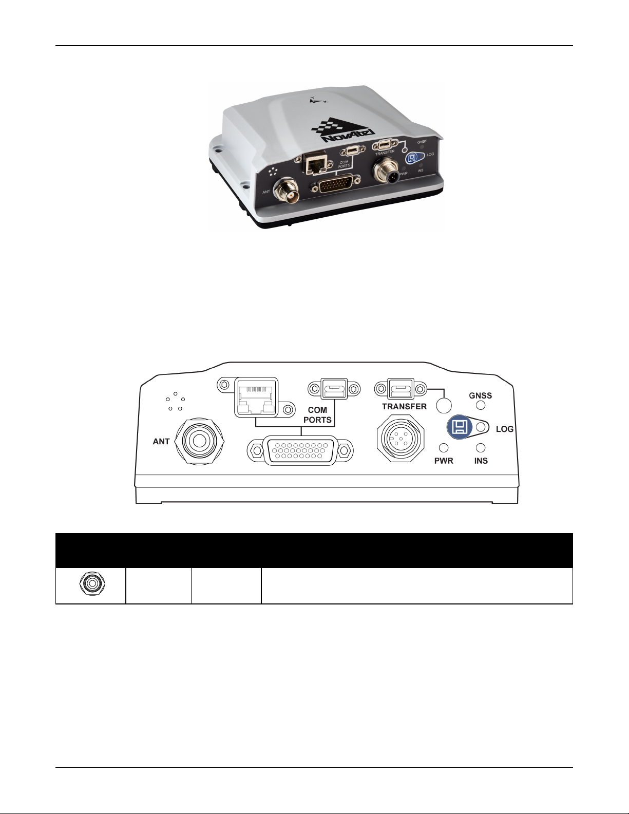
Figure 1: PwrPak7 Enclosure
PwrPak7 and PwrPak7-E1 technical specifications are provided in PwrPak7 Specifications on
page115.
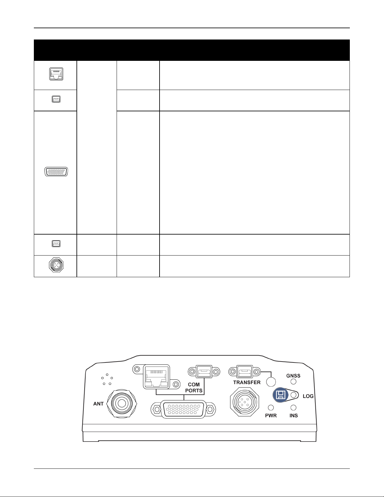
1.1 PwrPak7 Connectors
The PwrPak7 has several connectors for connecting the receiver to other components in the
GNSS system.
Connector Label
ANT TNC Connects the receiver to the GNSS antenna
Figure 2: PwrPak7 Connectors
Table 1: PwrPak7 Connectors
Connector
Type
Description
PwrPak7 Installation and Operation User Manual v1A 18
Chapter 1 PwrPak7 and PwrPak7-E1 Overview
Connector Label
COM
PORTS
Connector
Type
RJ45
USB Micro
A/B
DSUB
HD26
Description
Connects the receiver to an Ethernet network
Used to communicate to the receiver using a network
connection
A USB 2.0 port used to communicate from a computer to
the receiver using a USB cable
Provides access to communication signals on the receiver.
This includes:
l
3 Event inputs (LVCMOS)
l
3 Event outputs (LVCMOS)
l
1 Pulse Per Second output (LVCMOS)
l
1 CAN bus
l
3 serial ports
l
COM1 RS422/RS232 user selectable
l
COM2 RS422/RS232 user selectable
l
COM3 RS232
l
Wheel Sensor RS422 Quadrature Input
TRANSFER
PWR
USB Micro
A/B
SAL M12 5
pin
USB 2.0 port used to transfer files from the on board
memory to a USB stick or computer
Connects the receiver to the power supply
Refer to the PwrPak7 Connectors on page126 for connector details.
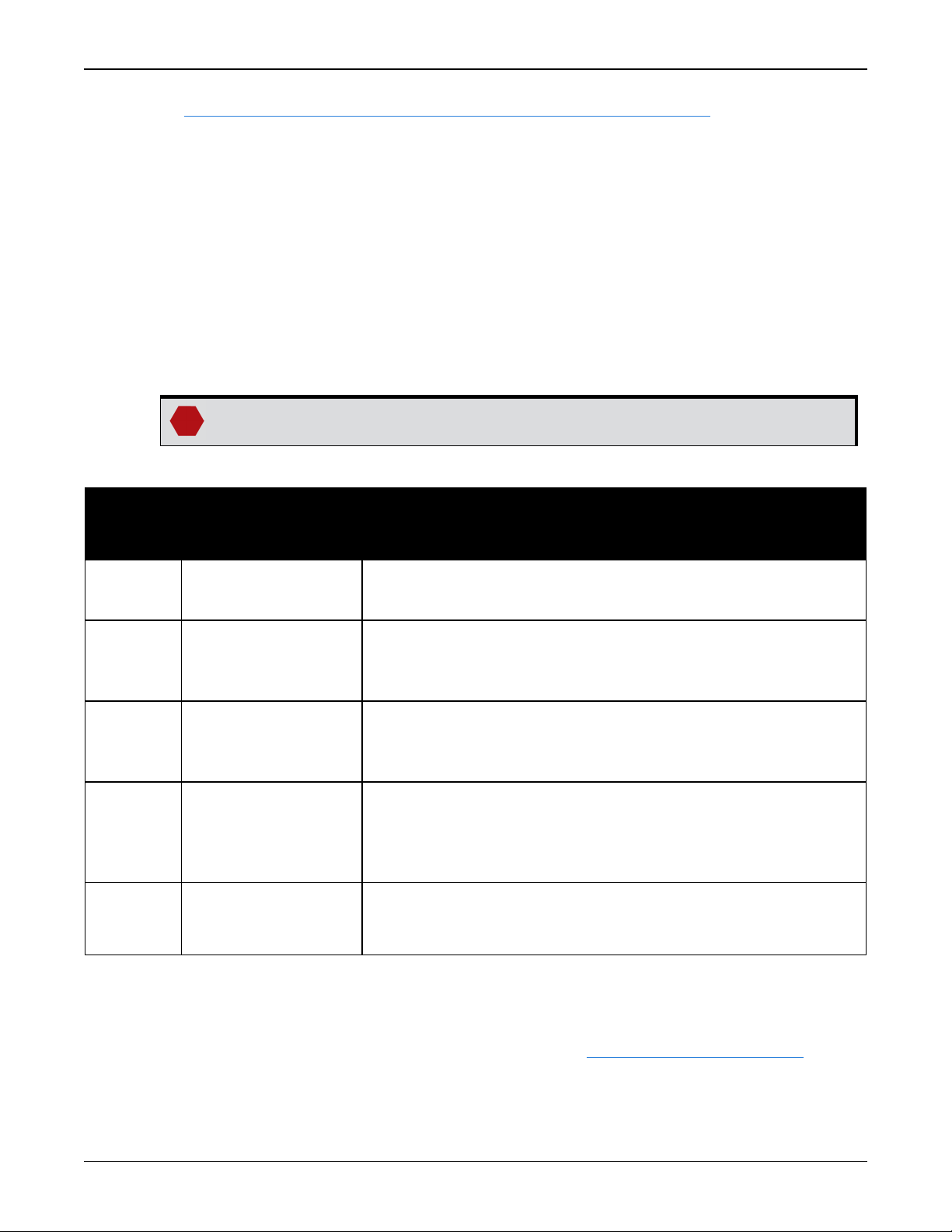
1.2 PwrPak7 LEDs
The PwrPak7 has five LEDs to indicate receiver status. It also has a button to start or stop data
logging to a file.
Figure 3: PwrPak7 Status Indicators
PwrPak7 Installation and Operation User Manual v1A 19

Chapter 1 PwrPak7 and PwrPak7-E1 Overview
The following tables provide information about the PwrPak7 LEDs and their states.
Table 2: PwrPak7 Status Indicators
Label Description
PWR Indicates the power status of the receiver
GNSS Indicates the position status of the receiver
Indicates the INS status of the receiver
INS
This LED is applicable only to SPAN capable PwrPak7 models (a PwrPak7-E1 or a
PwrPak7 with an external IMU)
TRANSFER
Indicates the status of logging or file-transfer to a USB stick or connection to a
computer as a USB Device
LOG Indicates the status of logging to the receiver internal memory
Table 3: PWR (Power) LED
State Description
Green solid Operational mode
Yellow solid In the process of booting
Error, for example invalid receiver AUTH code
Red solid
Receiver firmware or Web User Interface update in progress
Table 4: GNSS LED
State Description
PPP solution
Green solid
User Accuracy Level (UAL) Operational (STEADYLINE)
Green slow blink RTK integer ambiguity
Green fast blink
Single point or SBAS solution
UAL Warning
No solution
Yellow solid
UAL Out of Bounds
If the PwrPak7 is configured as a base station
Green solid Fixed position
Yellow solid Pending fixed position
Yellow blink Invalid fix
PwrPak7 Installation and Operation User Manual v1A 20

Chapter 1 PwrPak7 and PwrPak7-E1 Overview
State Description
Off INSinactive
Green solid INS solution good
Green slow blink INS alignment complete
Green fast blink INS solution free
Green/Yellow alternating blink High variance
Yellow blink INS aligning/determining orientation
Red solid Error
Table 6: TRANSFER LED
LEDState Description
USBstick plugged in, mounted and idle (lots of available
Green solid
memory)
Transfer port connected to a computer
Table 5: INS LED
Green slow blink Logging to USBstick (lots of available memory)
Green fast blink Transferring files to USB stick (lots of available memory)
Green/Yellow alternating slow
blink
Green/Yellow alternating fast
blink
Logging to USB stick (low memory)
Transferring files to USBstick (low memory)
Yellow solid USBstick plugged in, mounted and idle (low memory)
Yellow fast blink USB stick mounting/unmounting/busy
Red solid USBstick plugged in and mounted, but memory full
Red fast blink for 3 seconds Push button error or USBstick mount error
Off
No connection to the TRANSFER port or the USB stick is
unmounted
Table 7: LOG (Onboard Storage) LED
LEDState Description
PwrPak7 is connected to a computer as a mounted device
Off
See Access Internal Memory with a Computer on page71
PwrPak7 Installation and Operation User Manual v1A 21

Chapter 1 PwrPak7 and PwrPak7-E1 Overview
LEDState Description
Green blink Logging to internal memory (lots of memory available)
Green solid Internal logging stopped (lots of memory available)
Green/Yellow alternating blink Logging to internal memory (low memory)
Yellow solid Internal logging stopped (low memory)
Yellow fast blink Memory is mounting or unmounting/busy
Red solid
Red fast blink for 3 seconds Push button error
Internal memory full or corrupt
Refer to Repair Errors on the Internal Memory on page72
1.3 Related Documents and Information
After the OEM7 receiver is set up, the OEM7 Commands and Logs Reference Manual becomes the
primary source for command and log information. Each receiver has a specific set of features,
so some commands and logs may not be supported by your model.
For instructions on configuring and using SPAN functionality, refer to the OEM7 SPAN Installation
and Operation User Manual.
Refer to our web site docs.novatel.com/OEM7 for the latest documentation.
This manual does not cover OEM7 service and repair. Contact a local NovAtel dealer for service
or repair inquiries (refer to Customer Support on page15 for contact details).
PwrPak7 Installation and Operation User Manual v1A 22
Chapter 2 PwrPak7 Installation
This chapter provides instructions to install the PwrPak7 and create a GNSS receiver system.
2.1 Shipping Box
The following is provided with the PwrPak7:
l
Power cable – M12 connector to bare wires (01019764)
l
PwrPak7 COM1 Cable on page132 (01019765)
l
USB Cable, A Plug to Micro-B Plug with Ferrites (60723175)
l
PwrPak7 and PwrPak7-E1 Quick Start Guide (GM-14915152)
2.2 Additional Equipment Required
The following additional equipment is required for the GNSS receiver system:
l
A 9-36 VDC, fuse protected power supply capable of at least 15 W
l
A quality GNSS antenna, such as NovAtel’s VEXXIS®GNSS-500 or GNSS-800 series antennas
For a list of NovAtel GNSS antennas refer to www.novatel.com/antennas
l
A quality coaxial cable with a TNC male connector at the receiver end such as NovAtel’s GPSC016 model
The following equipment may also be needed, depending on the system configuration:
l
A computer/tablet/smartphone with Wi-Fi and a web browser or a computer with an RS-232
DB-9, Ethernet or USB port
l
Shielded Ethernet cable
Use a serial COM, USB or Wi-Fi connection to communicate with the receiver first. This
provides the ability to configure the computer and PwrPak7 before using Ethernet.
When the PwrPak7 is installed in a permanent location, such as in a building, it should be
protected by a lightning protection device according to local building codes. See Light-
ning Protection Installation and Grounding Procedure on page12.
2.3 Optional Accessories
The following optional accessories are available from NovAtel:
l
PwrPak7 All I/O Cable on page130 (01019766)
l
PwrPak7 IMU Cable on page133 (01019767)
l
Micro A to USB stick adapter, such as Tensility 10-00649 or equivalent
l
Optional external SPAN compatible IMU (not applicable to PwrPak7-E1)
PwrPak7 Installation and Operation User Manual v1A 23
Chapter 2 PwrPak7 Installation
See www.novatel.com/products/span-gnss-inertial-systems/span-imus/
l
Four M5 or #10 size screws for mounting
2.4 PwrPak7 Cables
To prevent damage to both the receiver and the cables, each connector can be inserted in only
one way.
Furthermore, the connectors used to mate the cables to the receiver require careful insertion
and removal. Observe the following when handling cables.
l
To insert a cable, make certain to use the appropriate cable for the PwrPak7 connector
l
Insert the connector until it is on straight and secure
l
To remove a cable, grasp it by the connector
Do not pull directly on a cable.
Table 8: PwrPak7 Cables
NovAtel
Part
Number
01019764
01019765
01019766
01019767
60723175
Cable Name Purpose
PwrPak7 Power
Cable on page129
Connects the PwrPak7 to an external power supply
SAL M12, 5 pin to bare wires
Provides connection to the COM1 serial port on the PwrPak7
PwrPak7 COM1 Cable
COM PORTS connector
on page132
HD26 to DB9
Provides connections for all of the signals available on the
PwrPak7 All I/O
PwrPak7 COM PORTS connector
Cable on page130
HD26 to three DB9 connectors and multiple bare wires
Provides connection from the COM1 serial port on the PwrPak7
PwrPak7 IMU Cable
on page133
COM PORTS connector to the communications port on an IMU
Enclosure
HD26 to SAL M12, 5-pin
USB Cable, A Plug to
Micro-B Plug with
Ferrites
Connects from the PwrPak7 USB COM PORTS connector to a
computer
2.5 Selecting a GNSS Antenna
NovAtel offers a variety of antennas, including single, dual and triple-frequency, triple-band and
wide-band reference GNSS antennas (refer to our web site: www.novatel.com/antennas for
details of available antennas). All antennas include band pass filtering and an LNA. The GNSS
antenna chosen depends on the particular application. Each model offers exceptional phase
PwrPak7 Installation and Operation User Manual v1A 24
Chapter 2 PwrPak7 Installation
center stability and a significant measure of immunity against multipath interference. Each
antenna has an environmentally sealed radome and all meet the European Union’s Restriction of
Hazardous Substances (RoHS) and Waste Electrical and Electronic Equipment (WEEE).
If a non-NovAtel GNSS antenna is chosen, a typical antenna LNA gain between 26 dB to 30 dB is
recommended in a rover station application.
For more information about antenna selection, see Importance of Antenna Selection on
page134.
2.6 Choosing a Coaxial Cable
An appropriate coaxial cable matches the impedances of the antenna and receiver (50 ohms)
and has a line loss not exceeding 10.0 dB. If the limit is exceeded, excessive signal degradation
may occur and the receiver may not meet performance specifications. NovAtel offers several
coaxial cables to meet GNSS antenna interconnection requirements, including:
l
5, 15 and 30 m antenna cable with TNC connectors on both ends (NovAtel part numbers GPSC006, GPS-C016 and GPS-C032)
NovAtel recommends using high quality coaxial cables because an impedance
mismatch is possible when using lower quality cables and this produces reflections
in the cable that increases signal loss. Although other high quality antenna cables
can be used, the performance specifications of the OEM7 receivers are warranted
only when used with NovAtel supplied accessories.
2.7 Power Supply Requirements for the PwrPak7
The PwrPak7 requires a power supply that provides:
l
a voltage in the range of +9 to +36 VDC
l
at least 15 W of power
See PwrPak7 Electrical and Environmental Specifications on page121 for more power supply
specifications.
The PwrPak7 has an internal power module that:
l
filters and regulates the supply voltage
l
protects against over-voltage, over-current, and high-temperature conditions
l
provides automatic reset circuit protection
If the voltage supplied is below the minimum specification, the receiver suspends
operation. If the voltage supplied is above the maximum specification, the receiver
may be permanently damaged, voiding the warranty.
The supply must be capable of providing enough current to operate the PwrPak7,
including the initial inrush transient. The supply must also be current limited to 6 A
with an external fuse.
PwrPak7 Installation and Operation User Manual v1A 25

Chapter 2 PwrPak7 Installation
The amount of power required depends on the number of constellations and signals
tracked, and the features enabled.
The power cable included with the PwrPak7 has a connector on the receiver end (SAL M12 5 pin)
and bare wires on the other end. Refer to PwrPak7 Power Cable on page129 for details about
the power cable.
2.8 PwrPak7 Installation Overview
When the appropriate equipment is selected, complete the following steps to set up and begin
using the NovAtel GNSS receiver.
PwrPak7 Installation and Operation User Manual v1A 26
Chapter 2 PwrPak7 Installation
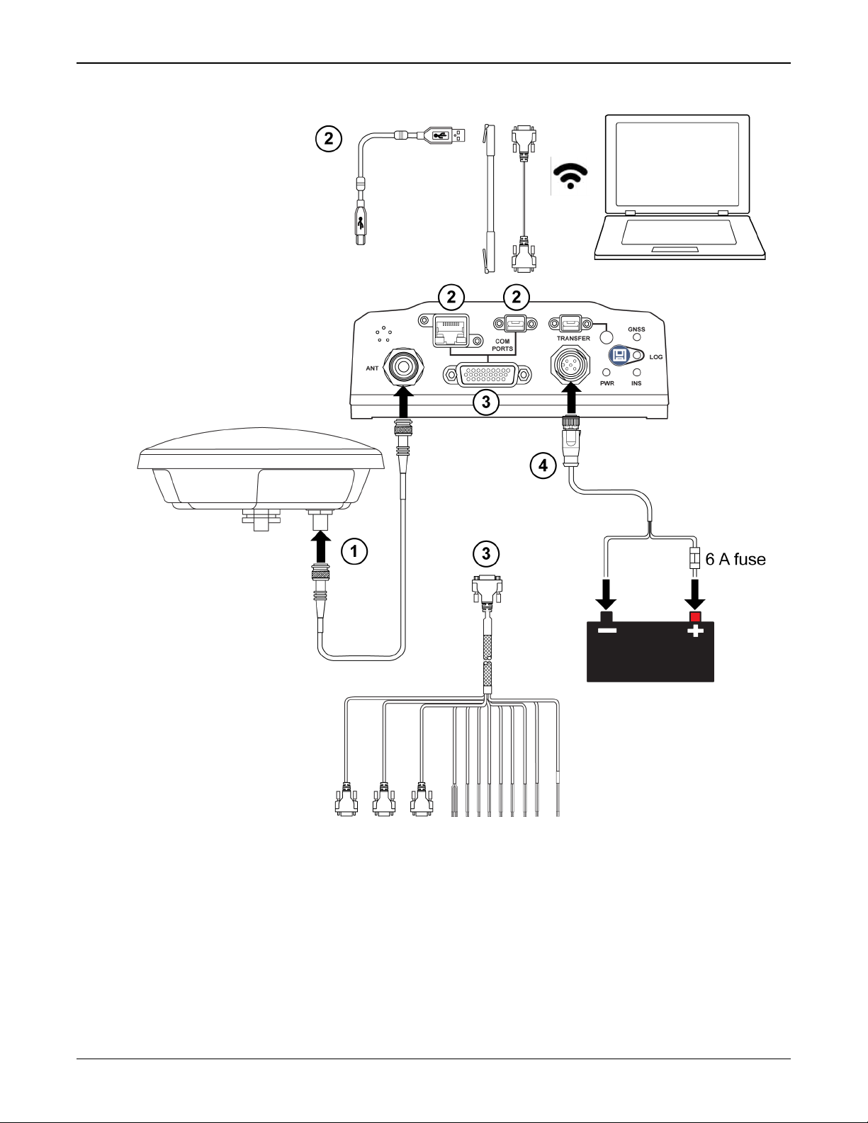
Figure 4: PwrPak7 Installation Example
1.
Mount the GNSS antenna. See Mounting the GNSS Antenna on the next page for more inform-
ation.
2.
Mount the receiver.
For a PwrPak7, refer to Mount the PwrPak7 on the next page.
For a PwrPak7-E1, refer to Mount the PwrPak7-E1 on page29.
3.
Connect one end of the antenna cable to the GNSS antenna and the other end of the cable to
the antenna connector (ANT) on the receiver.
PwrPak7 Installation and Operation User Manual v1A 27
Chapter 2 PwrPak7 Installation
The PwrPak7 supplies +5 VDC (200 mA maximum) to the antenna LNA through the center
conductor of the antenna cable. See Antenna LNA Power on the next page for more inform-
ation.
4.
Connect the receiver to other GNSS system components, such as a computer or data terminal, using the communication ports or Wi-Fi.
See Connect the PwrPak7 to Data Communication Equipment on page30.
5.
Connect other GNSS system components using the input and output lines.
See Connect I/O Signals to the PwrPak7 on page32.
6.
Connect the supplied power cable to the power port (PWR) on the receiver and then connect
the power cable to the power supply.
Ensure a 6 A slow blow fuse is incorporated in the power wiring.
See Connect Power to the PwrPak7 on page32 and Power Supply Requirements for the
PwrPak7 on page25 for details.
2.9 Mounting the GNSS Antenna
The OEM7 receiver is designed to operate with any NovAtel GNSS antenna. See Selecting a
GNSS Antenna on page24 for more information.
When installing the antenna:
l
Choose an antenna location with a clear view of the sky so each satellite above the horizon
can be tracked without obstruction. For more information on RF signal propagation and multipath, refer to the NovAtel application note APN-008 Discussions on RF Signal Propagation
and Multipath at www.novatel.com/support/.
l
Mount the antenna on a secure, stable structure capable of safe operation in the specific
environment.
l
Ensure the antenna cannot move due to dynamics.
2.9.1 Antenna LNA Power
NovAtel antennas and coaxial cables meet receiver RF input gain requirements. NovAtel coaxial
cables are designed to introduce no more than 10 dB loss and NovAtel antennas are equipped
with built-in LNAs that provide 26 dB of gain to the satellite signal received.
The power to the antenna LNA is provided through the receiver’s RF port center conductor.
OEM7 receivers provide +5 VDC ±5% at a maximum of 200 mA.
Antenna supply over current protection limits the LNA power.
If a short circuit or other problem causes an overload of the current supplied to the
antenna, the receiver hardware shuts down the power supplied to the antenna. To
restore power, power cycle the receiver. The Receiver Status word, available in the
RXSTATUS log (see OEM7 Commands and Logs Reference Manual), provides more
information about the cause of the problem.
PwrPak7 Installation and Operation User Manual v1A 28
Chapter 2 PwrPak7 Installation
2.10 Mount the PwrPak7
Mount the PwrPak7 on a secure, stable surface using four M5 or #10 size screws fastened
through the PwrPak7 mounting holes. The torque of the screws should not exceed 15 inch-lb.
See PwrPak7 Mechanical Specifications on page119 for drawings of the PwrPak7 dimensions
and locations of the mounting holes.
Wi-Fi Interface
The Wi-Fi interface SSID and default password are printed on a label on the bottom
of the PwrPak7. If you intend to use the Wi-Fi interface and NovAtel Web User
Interface, record the SSIDand default password before securing the PwrPak7 in its
mounting location.
The PwrPak7-E1 has additional mounting considerations, refer to Mount the
PwrPak7-E1 below for more information
2.11 Mount the PwrPak7-E1
Mount the PwrPak7-E1 in a fixed location where the distance from the PwrPak7-E1 to the GNSS
antenna phase center is constant. Ensure that the orientation with respect to the vehicle and
antenna is also constant. Secure the PwrPak7-E1 using four M5 or #10 size screws fastened
through the PwrPak7 mounting holes. The torque rate of the screw should not exceed 15 inch-lb.
See PwrPak7 Mechanical Specifications on page119 for drawings of the PwrPak7-E1 dimensions
and locations of the mounting holes.
For attitude output to be meaningful, the PwrPak7-E1 should be mounted such that the positive
Z-axis marked on the receiver points up and the Y-axis points forward through the front of the
vehicle, in the direction of track. If the PwrPak7-E1 is not mounted in this orientation, a rotational offset must be applied. See the OEM7 SPAN Installation and Operation User Manual for
more information.
Also, it is important to measure the distance from the PwrPak7-E1 center of navigation to the
antenna phase center (the Antenna Lever Arm), on the first usage, on the axis defined on the
PwrPak7-E1. See the OEM7 SPAN Installation and Operation User Manual. See also PwrPak7
Mechanical Specifications on page119 for the center of navigation location.
Ensure the PwrPak7-E1 cannot move due to dynamics and that the distance and relative direction between the antenna and the PwrPak7-E1 is fixed.
The closer the antenna is to the PwrPak7-E1, particularly in the horizontal plane,
the more accurate the position solution. Also, the measurements entered using the
SETINSTRANSLATION command must be as accurate as possible, or at least
more accurate than the GNSS positions being used. For example, a 10 cm error in
recording the antenna offset will result in at least a 10 cm error in the output.
Millimeter accuracy is preferred.
The offset from the PwrPak7-E1 to the antenna, and/or a user point device, must
remain constant especially for RTK or DGNSS data. Ensure the PwrPak7-E1,
antenna and user point device are bolted in one position perhaps by using a custom
bracket.
PwrPak7 Installation and Operation User Manual v1A 29
Chapter 2 PwrPak7 Installation
Wi-Fi Interface
The Wi-Fi interface SSID and default password are printed on a label on the
bottom of the PwrPak7-E1. If you intend to use the Wi-Fi interface and NovAtel
Web User Interface, record the SSID and default password before securing the
PwrPak7-E1 in its mounting location.
2.12 Connect the PwrPak7 to Data Communication Equipment
The PwrPak7 can communicate with other devices in the system, such as computers and data
loggers, using serial, USB, Wi-Fi or Ethernet ports.
l
Serial Ports below
l
USB Ports on the next page
l
Wi-Fi on the next page
l
Ethernet Port on page32
The PwrPak7 also has a CAN bus port for communication with other CAN bus compatible devices.
See CAN Bus Port on page32.
2.12.1 Serial Ports
The PwrPak7 has three serial ports: COM1, COM2 and COM3. These ports are available on the
HD26 COM PORTS connector. Refer to PwrPak7 Connectors on page126 for the pin out of this
connector.
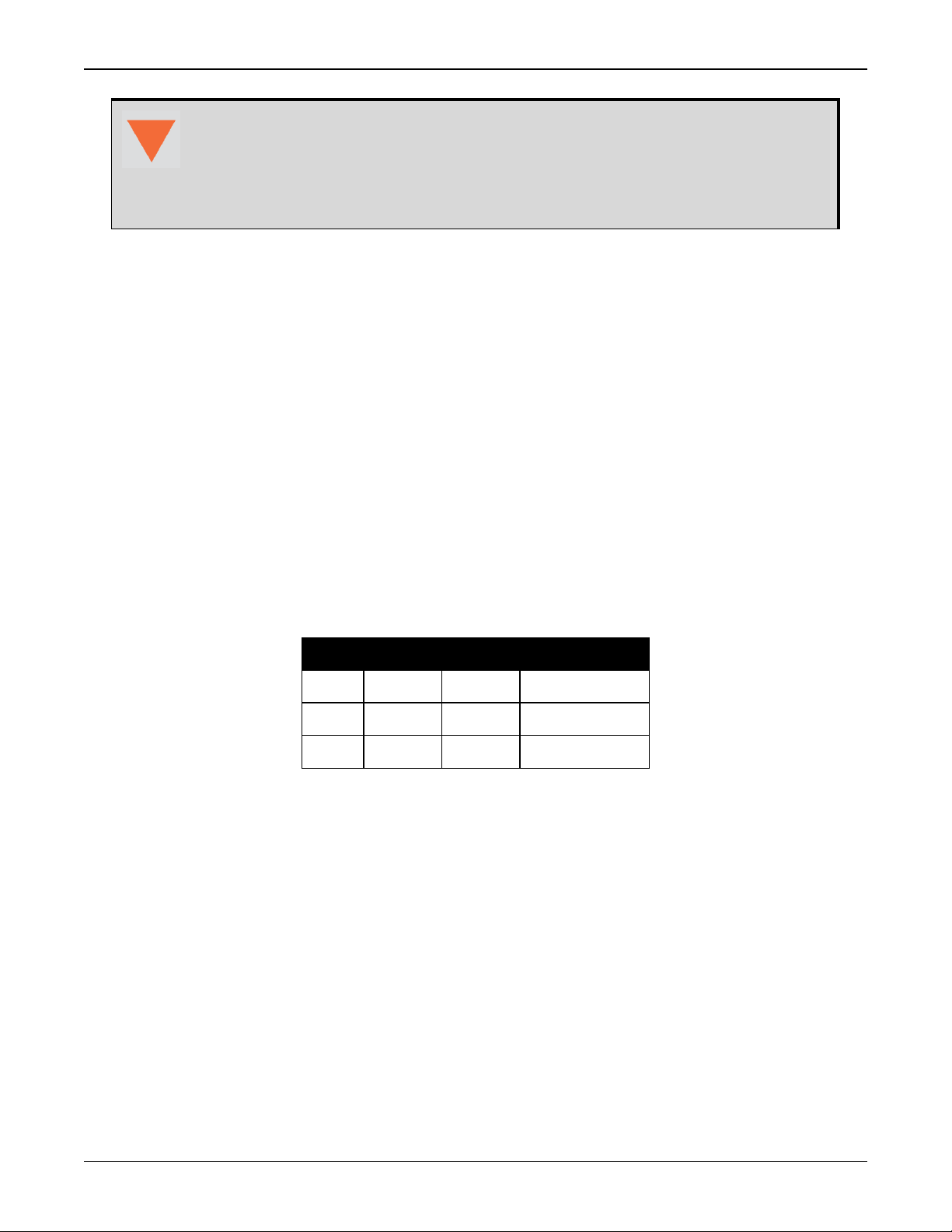
Table 9: PwrPak7 Serial Port Protocol
Port RS-232 RS-422 Flow Control
COM1 Yes Yes RTS/CTS
COM2 Yes Yes No
COM3 Yes No No
COM1 and COM2 can operate using RS-232 protocol or RS-422 protocol. To change the serial
port protocol, use the SERIALPROTOCOL command.
COM1 can operate using hardware flow control when the protocol is set to RS-232. To enable or
disable, hardware flow control (handshaking), use the SERIALCONFIG command.
Port settings (bit rate and parity, for example) are software configurable. See Communications
with the Receiver on page37 for information about configuring the serial ports. Also see
PwrPak7 Data Communication Specifications on page123 for the serial port specifications.
To connect to a serial port:
1.
Connect the PwrPak7 All I/O cable (PN: 01019766), or a custom made cable, to the HD26
COM PORTS connector.
PwrPak7 Installation and Operation User Manual v1A 30
 Loading...