

Novatel ProPak6 Quick Start Manual
1
ProPak6™
GM-14915125 Rev 3 August 2014
QUICK START GUIDE
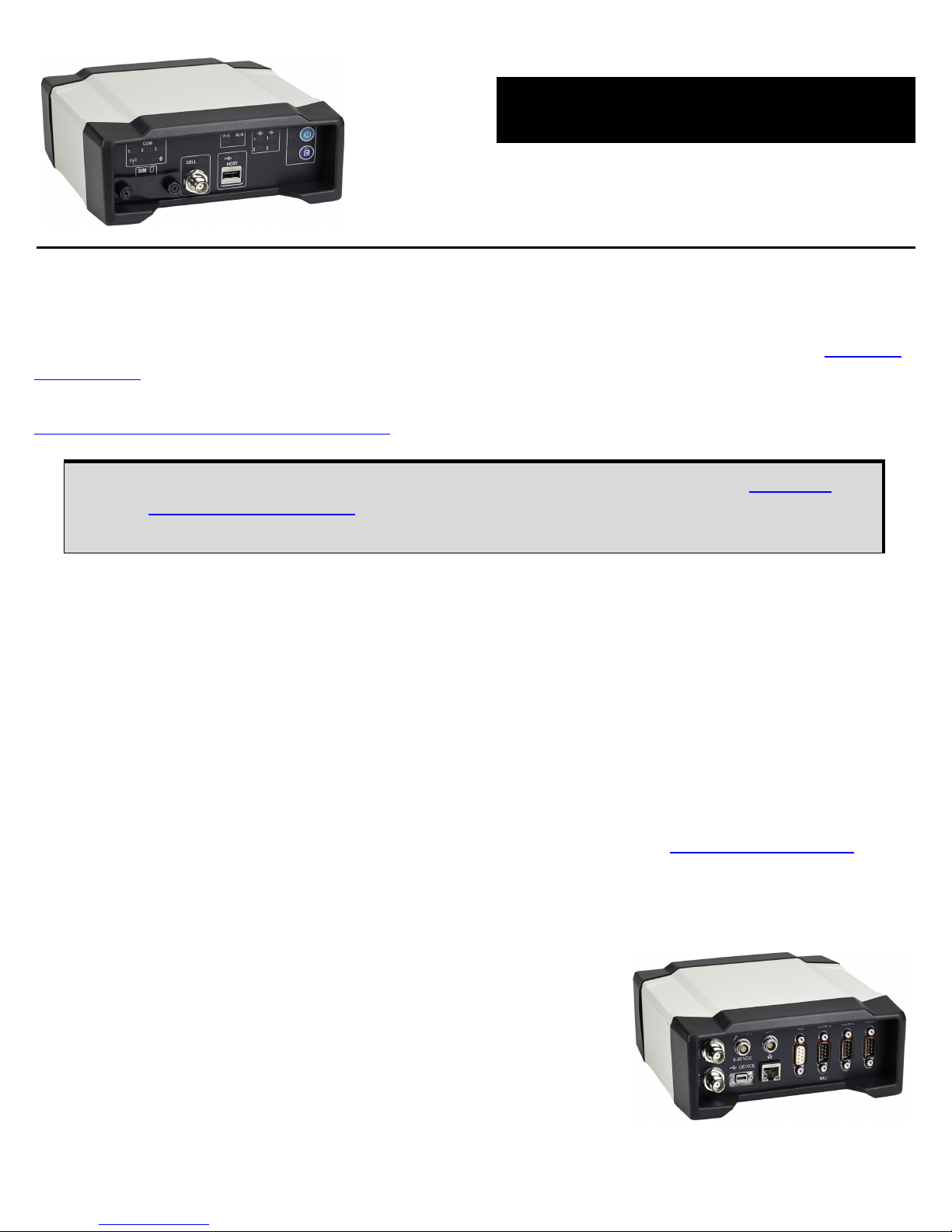
ProPak6 - Front
This guide provides the basic information needed to set up and use a NovAtel® ProPak6.
USER MANUALS
For detailed information on the installation and operation of the NovAtel receiver, download the ProPak6
User Manual (OM-20000148).
For detailed information on the logs and commands used to configure the NovAtel receiver, download the
OEM6 Family Firmware Reference Manual
(OM-20000129).
BOX CONTENTS
The following is provided with the ProPak6 (NovAtel part number):
• ProPak6 receiver with built in Wi-Fi, Bluetooth
®
, USB 2.0 and 4 GB of onboard memory
• 12 VDC power adapter (CLA) with slow blow fuse (01017663)
• Null modem serial cable (01017658)
• DB9 male extension cable (01018520)
• I/O DB9 male interface cable (01018519)
• Mounting bracket and screws (70023096, quantity 2 and 28523058, quantity 4)
Additional Equipment Required
The additional equipment listed below is required for a typical setup (refer to ProPak6 User Manual (OM-
20000148) for further details).
• A standard 12 VDC power outlet or 9-36 VDC power supply capable of at least 14 W
• A Windows computer with a RS-232 DB-9, Ethernet or USB port
• A quality GNSS antenna, such as NovAtel’s 700 or ANT series
• An antenna cable with a TNC male connector at the receiver end
such as NovAtel’s GPS-C016 model
• A cellular antenna and SIM card (model dependant)
If a SPAN® GNSS+INS capable ProPak6 was purchased, download the SPAN on
OEM6 Quick Start Guide (GM-14915112). To purchase SPAN firmware, contact
Sales@NovAtel.com to obtain SPAN software functionality for your receiver.
ProPak6 - Back
2
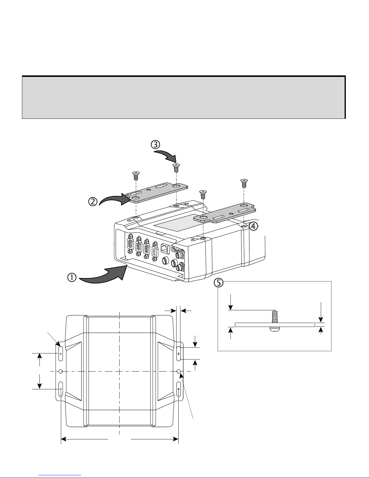
PROPAK6 MOUNTING
Use brackets and screws provided with the ProPak6 to facilitate mounting the receiver to a surface. Prior
to connecting any cables and installing the ProPak6 in a fixed position, attach the supplied mounting
brackets to the ProPak6.
Figure 1: Mounting Bracket Installation
High Vibration ProPak6 Mounting
For high vibration installations, mount the ProPak6 directly using 1/4” 20-UNC threaded
screws (4 locations). Vibration dampeners or isolators for additional vibration reduction
may also be used (user supplied).
Align the included mounting
brackets (2) over the
mounting holes of
the ProPak6
Thread the included mounting
screws (4) through the bracket holes and
into the ProPak6 mounting hole
Flip the ProPak6
upside down
Use a screw driver
to securely
tighten screws (4)
60.0
6.8
18.20
6 mounting features sized for 1/4” or M6 hardware.
Accommodates 5/8” or 16 mm diameter washer.
(Ø6.8)
Typical
200.0
If mounting a ProPak6 to a fixed location without
using the provided backets, the total length of the
mounting screw must have a range of T+0.25”
minimum by T+0.375” maximum. Use 1/4”-20
screws to secure the receiver, torqued to
2 foot-pound (24 inches-pounds).
Thickness of Mounting plate (T)
[T + 0.25”] min - [T + 0.375”] max
Total length of screw
3
GETTING TO KNOW THE PROPAK6
Refer to ProPak6 User Manual (OM-20000148) for details on all ProPak6 connectors, labelling and LEDs
as well as detailed installation and operation instructions. Refer to the OEM6 Firmware Reference Manual
- OM-20000129 for details regarding any ProPak6 logs or commands.
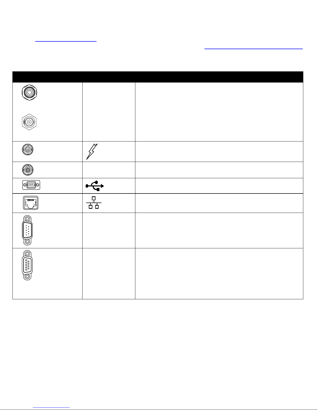
Table 1: ProPak6 - Back Connector Definitions
Connector Type Connector Label Description
GNSS Antenna
External Oscillator
ANT 1
ANT 2
or
ANT1
OSC
GNSS GPS1 and GPS2 antennas (TNC) (model dependant)
or
GNSS GPS1 antenna (TNC) and external oscillator (BNC) (model
dependant)
Power
PWR
4-pin LEMO power connector
Expansion
EXP. 9-pin LEMO expansion port for CAN1 and CAN2
USB
DEVICE
USB Device (Type micro B) connector (high speed only) 480 Mbps
Ethernet
Ethernet RJ45 connector
I/O
I/O 4 Event Input/3 Event Output (DB9 female connector)
I/O port is configurable
Serial Communication
Ports
COM1
COM2
COM3/IMU
COM1, COM2, COM3/IMU DB9 male communications port
RS-232 (RS-422 selectable via software)
4
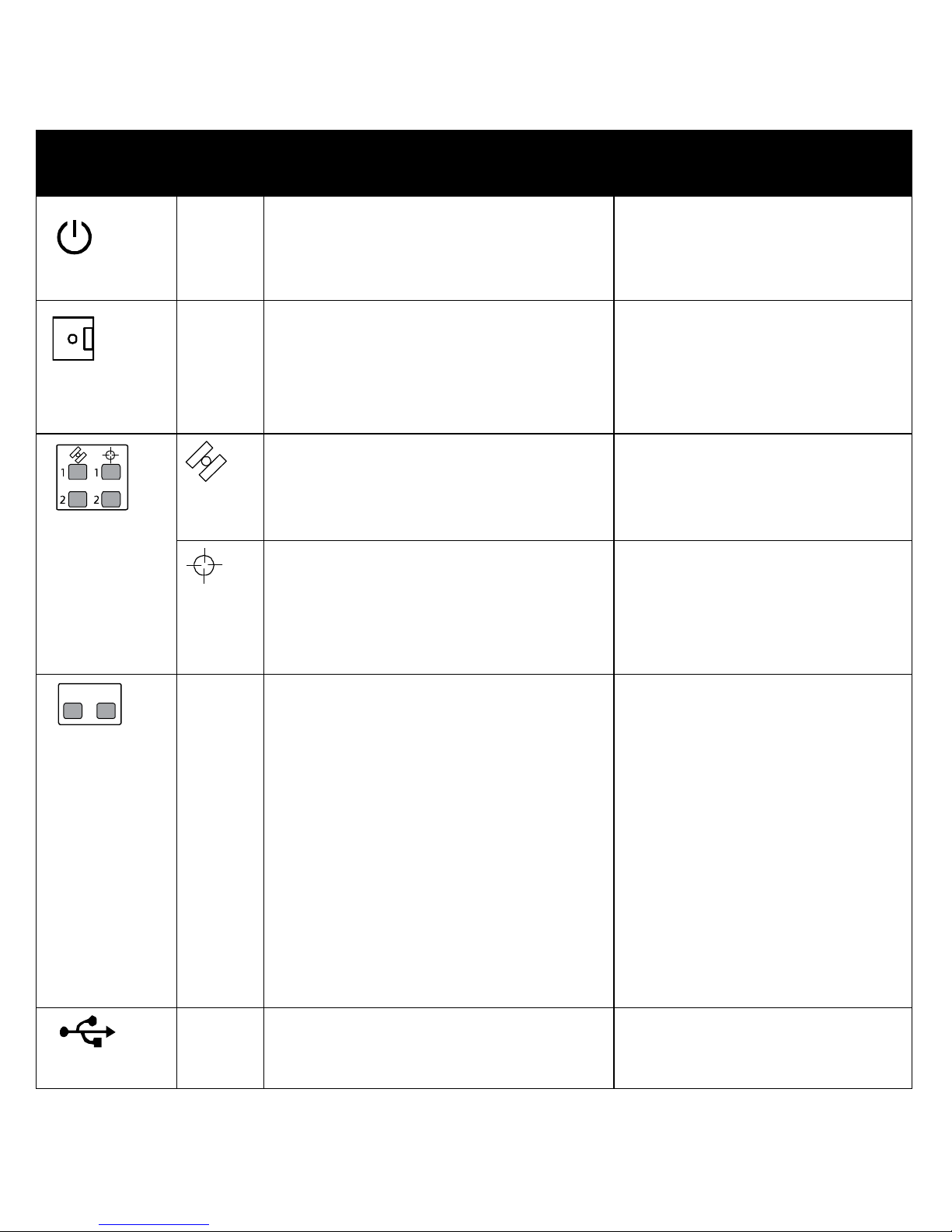
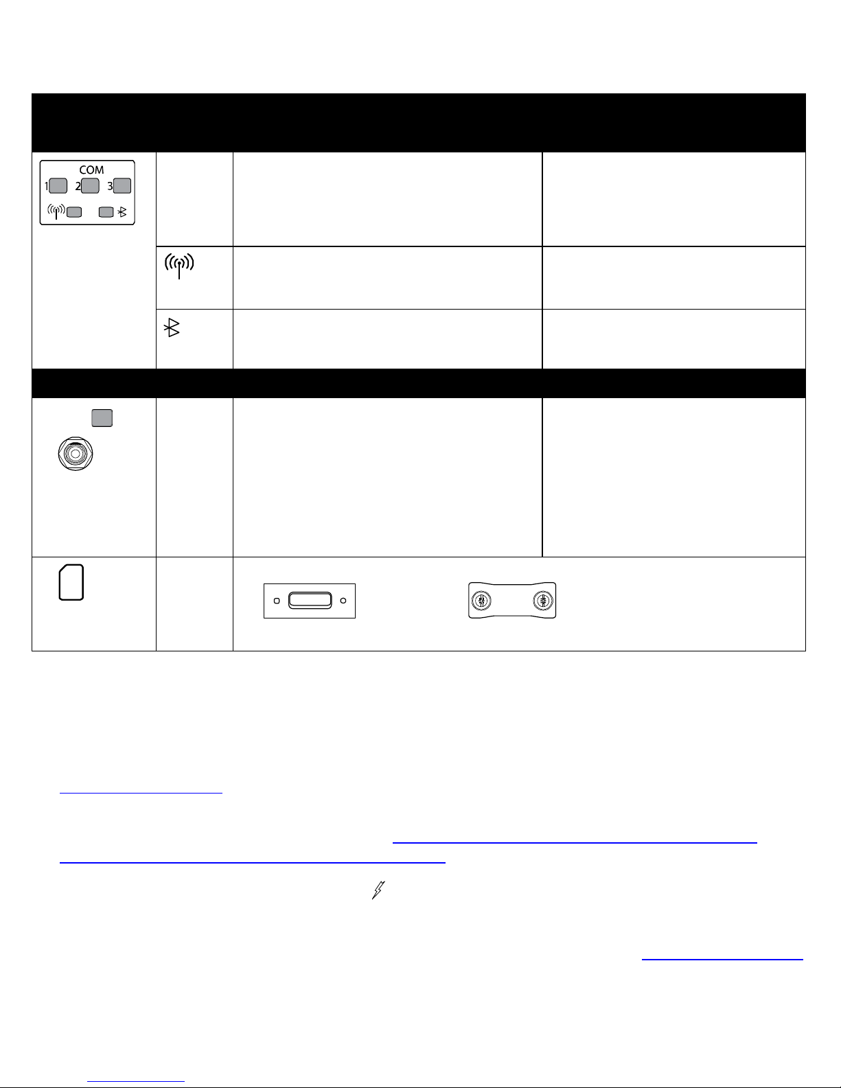
Table 2: ProPak6 - Front Label Definitions
Button/
Connector/LED
Type
Label LED States Description
Power
N/A Off
Solid red = Valid power
Solid green = Operational mode
Power button and status LED
Press and hold the power button a
minimum of 3 s and maximum of 10 s
to power down the ProPak6
Logging
N/A Off
Solid green = >40% memory available
Solid amber = 20-40%
Solid red = <20%
Alternate green/amber = busy
Logging button with user configurable
status LED
Tracking
Off = 0 satellites
Solid red = 1-3 satellites
Solid amber = 4-5 satellites
Solid green = 6+ satellites
Indicates number of satellites being
tracked by the corresponding receiver
Position
Off = no fix
Blink amber = single point
Solid amber = converging accuracy
Solid green = converged accuracy
Blink green = PSR/PDP corrections
Indicates satellite position status for
the corresponding receiver
INS
ALN
INS
Off
Solid red = active
Blink red = error
Alternate red/amber = orientation or initial
position
Alternate green/amber = solution free
Solid amber = aligning
Blink amber = high variance
Green solid = solution good
Blink green = alignment complete
ALN
Off = no dual card/<4 satellites
Solid amber = FLOAT solution
Solid Green = fixed solution
INS status indication (SPAN
configuration only)
ALIGN heading status indication (Dual
antenna configuration only)
HOST Off
Solid red = idle
Blink red = active
USB Host (Type A) connector ProPak6 built in USB Host with status
LED
INS ALN
5
SETTING UP A PROPAK6
Complete the following steps to connect and power the ProPak6. Be sure to mount the antenna to a
secure, stable structure with an unobstructed view of the sky.
1. Connect GNSS antennas to the ANT1 port and ANT2 port (if equipped) found on the back of the
ProPak6 and connect an external oscillator (if equipped) to the adjacent OSC port. Refer to the
ProPak6 User Manual
(OM-20000148) for detailed instructions.
2. Connect the COM1 or USB port on the receiver to the USB or serial port on a computer. If using a USB
connection, install the USB drivers (available www.novatel.com/support/firmware-software-and-
manuals/firmware-software-updates/novatel-connect/).
3. Connect the power cable connector to the PWR port on the back of the ProPak6.
4. Connect a cellular antenna to the CELL port on the front of the ProPak6 (if equipped).
5. Configure and/or enable ports, radios and receiver settings as required (refer to ProPak6 User Manual
(OM-20000148) for details).
COM 1, 2
and 3
Off
Blink green = Tx RS-232
Blink red = Rx RS-232
Solid green = RS-422
Transmit/Receive indication (COM 1, 2
and/or 3)
Wi-Fi
Off
Solid blue = ready state
Wi-Fi radio status LED
Bluetooth
Off
Solid blue = ready state
Bluetooth radio status LED
CELLULAR - OPTIONAL
CELL Off
Solid red = no signal
Blink red = error
Solid amber = cell network available-IP not
available
Blink green = IP activity (Tx/Rx)
Solid green = IP available/idle
Fully integrated TNC cellular modem
antenna connector (GPRS/HSPA) and
status LED
Mini-SIM only
(25 mm x 15 mm)
SIM Push-push style SIM card holder
Remove SIM card holder cover to insert card; replace cover to avoid damaging card.
Table 2: ProPak6 - Front Label Definitions
Button/
Connector/LED
Type
Label LED States Description
Open
Covered
 Loading...