

Page 1
MiLLennium
OM-20000016 Rev 3
ââââ
GPSCard
and Enclosures
(PowerPak
Guide to Installation & Operation
II & ProPak
II)
GPSCard™ Products NovAtel Inc.
Page 2

MiLLenniumâGPSCardTMand
Enclosures
Guide to Installation & Operation
Publication Number: OM-20000016
Revision Level: 3
Date: 07/06/99
This manual is a companion to the MiLLennium Command Descriptions manual (NovAtel part number OM-20000041).
Proprietary Notice
Information in this document is subject to change without notice and does not represent a commitment on the part of
NovAtel Inc. The software described in this document is furnished under a license agreement or non-disclosure
agreement. The software may be used or copied only in accordance with the terms of the agreement. It is against the law
to copy the software on any medium except as specifically allowed in the license or non-disclosure agreement.
No part of this manual may be reproduced or transmitted in any form or by any means, electronic or mechanical,
including photocopying and recording, for any purpose without the express written permission of a duly authorized
representative of NovAtel Inc.
The information contained within this manual is believed to be true and accurate at the time of publication.
NovAtel, MiLLenium, ProPak, PowerPak, GPSolution, RT-2, RT-20, and Narrow Correlator are registered trademarks of
NovAtel Inc.
GPSCard and GPSAntenna are trademarks of NovAtel Inc.
All other brand or product names are either trademarks or registered trademarks of their respective holders.
© 1999 NovAtel Inc. All rights reserved
Unpublished rights reserved under International copyright laws.
Printed in Canada on recycled paper. Recyclable.
2 MiLLennium GPSCardand Enclosures Guide to Installation & Operation
Page 3

Table Of Contents
TABLEOF CONTENTS
TABLE OF CONTENTS
FOREWORD 8
1 INTRODUCTION 9
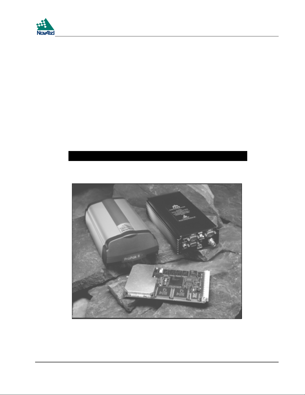
MiLLennium GPSCard.........................................................................................................................9
PowerPak II ........................................................................................................................................11
ProPak II.............................................................................................................................................12
2 HARDWARE CONFIGURATION 13
MiLLennium GPSCard.......................................................................................................................13
Antenna........................................................................................................................................14
Antenna Considerations...............................................................................................................14
Antenna Cable Considerations.....................................................................................................15
Principal Power Supply ...............................................................................................................15
Optional LNA Power Supply....................................................................................................... 15
RF Section ...................................................................................................................................15
Digital Electronics Section..........................................................................................................16
Communication Ports ..................................................................................................................16
Optional User-Supplied External Oscillator ................................................................................17
3 INSTALLATION 18
Minimum Configuration.....................................................................................................................19
Anti-Static Precautions .......................................................................................................................19
Installation Procedure .........................................................................................................................19
Mounting the Printed Circuit Board.............................................................................................19
Preparing the Data, Signal & Power Harness..............................................................................20
4 OPERATION 23
Communications with the Receiver....................................................................................................23
Serial Port Default Settings..........................................................................................................24
Communicating Using a Remote Terminal..................................................................................24
Communicating Using a Personal Computer...............................................................................24
Getting Started....................................................................................................................................24
Power On.....................................................................................................................................25
DOS.............................................................................................................................................26
Microsoft Windows 3.1 or higher................................................................................................27
5 FIRMWARE UPGRADES & UPDATES 28
Upgrading Using the $AUTH Command............................................................................................28
Updating Using the LOADER Utility.................................................................................................29
Transferring Firmware Files........................................................................................................29
Using the LOADER Utility .........................................................................................................30
MiLLennium GPSCard and Enclosures Guide to Installation & Operation 3
Page 4

Contents
APPENDICES
A Anti-Static Practices..........................................................................................................31
B Millennium Technical Specifications................................................................................33
C Powerpak II.......................................................................................................................42
D Propak II............................................................................................................................52
E Edge-View Of Connector P1.............................................................................................65
F Some Common Unit Conversions.....................................................................................66
G Replacement Parts.............................................................................................................67
H Index ................................................................................................................................68
TABLES
1 Common Feature Summary - MiLLennium Models.........................................................10
2 Disabled OEM2 Connector Pins........................................................................................20
3 Antenna LNA Power Configuration..................................................................................21
4 Prime Static Accumulators................................................................................................32
5 64 Pin I/O Connector Description .....................................................................................40
6 Serial Port Pin-Out Description.........................................................................................50
7 I/O Port Pin-Out Description.............................................................................................50
8 Straight Cable Pin Configurations..................................................................................... 60
9 Null Modem Cable Pin Configurations.............................................................................61
10 I/O Port Pin-Out Description.............................................................................................62
FIGURES
1 MiLLennium GPSCard .......................................................................................................9
2 MiLLennium System Functional Diagram........................................................................13
3 Typical System Configuration...........................................................................................18
4 LNAPowerJumperP301–3Cases.................................................................................21
5 Typical Operational Configuration....................................................................................23
6 Sample GPSolution Screen ...............................................................................................25
7 Main screen of LOADER program...................................................................................30
8 MiLLennium Board Dimensions .......................................................................................33
9 L1/L2 Series Side & End Views ....................................................................................... 34
10 PowerPak II Front Panel ...................................................................................................42
11 Cigarette-Lighter Power Adapter......................................................................................43
12 Y-Type Null-Modem Cable..............................................................................................43
13 Opening the PowerPak II Enclosure..................................................................................45
14 Typical PowerPak II Installation Configuration................................................................46
15 Connections on the MiLLennium......................................................................................48
16 Installing the Ground Connector on the MiLLennium ......................................................48
17 ProPak II Front End-Cap...................................................................................................52
18 ProPak II Rear End-Cap....................................................................................................52
19 Power Cables ....................................................................................................................53
20 ProPak II Installation Configuration Possibilities..............................................................55
21 Typical Operational Configuration....................................................................................56
22 Removal of Connectors.....................................................................................................56
23 Mounting Bracket..............................................................................................................58
24 Mounting Bracket Drill Holes – Dimensions....................................................................59
4 MiLLennium GPSCard and Enclosures Guide to Installation & Operation
Page 5

Warranty Policy
WARRANTY POLICY
NovAtel Inc. warrants that its Global Positioning System (GPS) products are free from defects in materials and
workmanship, subject to the conditions set forth below, for the following periods of time:
GPSCard Series One (1) Year
PowerPak Enclosure One (1) Year
ProPak Enclosure One (1) Year
GPSAntenna Series One (1) Year
Cables and Accessories Ninety (90) Days
Software Support One (1) Year
Date of sale shall mean the date of the invoice to the original customer for the product. NovAtel’s responsibility
respecting this warranty is limited solely to product repair at an authorized NovAtel location only. Determination of
repair will be made by NovAtel personnel or by technical personnel expressly authorized by NovAtel for this purpose.
THE FOREGOING WARRANTIES DO NOT EXTEND TO (I) NONCONFORMITIES, DEFECTS OR ERRORS IN
THE PRODUCTS DUE TO ACCIDENT, ABUSE, MISUSE OR NEGLIGENT USE OF THE PRODUCTS OR USE IN
OTHER THAN A NORMAL AND CUSTOMARY MANNER, ENVIRONMENTAL CONDITIONS NOT
CONFORMING TO NOVATEL’S SPECIFICATIONS, OR FAILURE TO FOLLOW PRESCRIBED
INSTALLATION, OPERATING AND MAINTENANCE PROCEDURES, (II) DEFECTS, ERRORS OR
NONCONFORMITIES IN THE PRODUCTS DUE TO MODIFICATIONS, ALTERATIONS, ADDITIONS OR
CHANGES NOT MADE IN ACCORDANCE WITH NOVATEL’S SPECIFICATIONS OR AUTHORIZED BY
NovAtel, (III) NORMAL WEAR AND TEAR, (IV) DAMAGE CAUSED BY FORCE OF NATURE OR ACT OF ANY
THIRD PERSON, (V) SHIPPING DAMAGE; OR (VI) SERVICE OR REPAIR OF PRODUCT BY THE DEALER
WITHOUT PRIOR WRITTEN CONSENT FROM NovAtel.
IN ADDITION, THE FOREGOING WARRANTIES SHALL NOT APPLY TO PRODUCTS DESIGNATED BY
NovAtel AS BETA SITE TEST SAMPLES, EXPERIMENTAL, DEVELOPMENTAL, PREPRODUCTION, SAMPLE,
INCOMPLETE OR OUT OF SPECIFICATION PRODUCTS OR TO RETURNED PRODUCTS IF THE ORIGINAL
IDENTIFICATION MARKS HAVE BEEN REMOVED OR ALTERED.
THE WARRANTIES AND REMEDIES ARE EXCLUSIVE AND ALL OTHER WARRANTIES, EXPRESS OR
IMPLIED, WRITTEN OR ORAL, INCLUDING THE IMPLIED WARRANTIES OF MERCHANTABILITY OR
FITNESS FOR ANY PARTICULAR PURPOSE ARE EXCLUDED.
NovAtel SHALL NOT BE LIABLE FOR ANY LOSS, DAMAGE OR EXPENSE ARISING DIRECTLY OR
INDIRECTLY OUT OF THE PURCHASE, INSTALLATION, OPERATION, USE OR LICENSING OR PRODUCTS
OR SERVICES. IN NO EVENT SHALL NovAtel BE LIABLE FOR SPECIAL, INDIRECT, INCIDENTAL OR
CONSEQUENTIAL DAMAGES OF ANY KIND OR NATURE DUE TO ANY CAUSE.
There are no user serviceable parts in the MiLLennium and no maintenance is required. When the status code indicates
that a unit is faulty, replace with another unit and return the faulty unit to NovAtel Inc.
You must obtain a RETURN MATERIAL AUTHORIZATION (RMA) number by calling NovAtel Customer
Service at 1-800-NOVATEL (Canada and the U.S. only or 403-295-4900 before shipping any product to NovAtel or
Dealer.
Once you have obtained an RMA number, you will be advised of proper shipping procedures to return any defective
product. When returning any product to NovAtel, please return all original diskettes along with the defective product in
the original packaging to avoid ESD and shipping damage.
MiLLennium GPSCard and Enclosures Guide to Installation & Operation 5
Page 6

Customer Service
CUSTOMER SERVICE
If you require customer service, please provide the following information along with a detailed description of the problem
when you call or write:
Serial No. ______________________________________ Model No. _________________________________________
Software Release No. _____________________________
Date Purchased: _________________________________
Purchased from: ____________________________________________________________________________________
User name: _____________________________________ Title:______________________________________________
Company: _________________________________________________________________________________________
Address: __________________________________________________________________________________________
City:___________________________________________ Prov/State: _________________________________________
Zip/Postal Code: _________________________________ Country:___________________________________________
Phone #: _______________________________________ Fax #: _____________________________________________
E-mail: ________________________________________
MiLLennium interface: Computer type: ___________________________Operating Shell: ______________________
Other interface used:_________________________________________________________________________________
Please provide a complete description of any problems you may be experiencing, or the nature of your inquiry (attach
additional sheets if needed):
__________________________________________________________________________________________________
__________________________________________________________________________________________________
__________________________________________________________________________________________________
__________________________________________________________________________________________________
__________________________________________________________________________________________________
You may photocopy and fax this page, call, or mail the above information to the address listed below.
For customer support, contact the NovAtel GPS Hotline at 1-800-NOVATEL or 403-295-4900;sendafaxto
403-295-4901; send e-mail to support@novatel.ca, or write to:
NovAtel Inc.
GPS Customer Service
1120 68 Avenue NE
Calgary, Alberta, Canada
T2E 8S5
6 MiLLennium GPSCard and Enclosures Guide to Installation & Operation
Page 7

Notice
FCC NOTICE
The following statements refer only to a MiLLennium GPSCard in a ProPak II or PowerPak II enclosure, not the card on
its own:
The United States Federal Communications Commission (in 47 CFR 15) has specified that the following notices be
brought to the attention of users of the PowerPak II and the ProPak II.
“This equipment has been tested and found to comply with the limits for a class A digital device, pursuant to Part 15 of
the FCC rules. These limits are designed to provide reasonable protection against harmful interference when the
equipment is operated in a commercial environment. This equipment generates, uses, and can radiate radio frequency
energy and, if not installed and used in accordance with the instruction manual, may cause harmful interference to radio
communications. Operation of this equipment in a residential area is likely to cause harmful interference in which case
the user will be required to correct the interference at his own risk.”
“Changes or modifications not expressly approved by the party responsible for compliance could void the user’s authority
to operate the equipment.”
Important: In order to maintain compliance with the limits of a Class A digital device, it is required to use properly
shielded interface cables (such as Belden #9539 or equivalent) when using the serial data ports, and
double-shielded cables (such as Belden #9945 or equivalent) when using the I/O strobe port.
CAUTION !
Handle with Care
Use Anti-Static Precautions
This warning is especially true for the MiLLennium GPSCard on its own. Please see Appendix A, Page 31 for handling
electrostatic discharge-sensitive (ESD) devices.
Important:ProPak II and PowerPak II incorporate circuitry to absorb most static discharges. However, severe static
shock may cause inaccurate operation of the unit.
MiLLennium GPSCard and Enclosures Guide to Installation & Operation 7
Page 8

Foreword
FOREWORD
Congratulations!
Congratulations on purchasing your MiLLennium GPSCard. The MiLLennium
a dual-frequency capable GPS receiver designed for original equipment manufacturer (OEM) applications. This Guide is
written for the OEM system integrator.
=
NovAtel’s third-generation GPSCard, is
,
Scope
This Guide contains sufficient information on the installation and operation of the MiLLennium to allow you to
effectively integrate and fully operate it. As such, it is beyond the scope of this Guide to provide details on service or
repair. Please contact your local NovAtel dealer for any customer-service related inquiries.
The MiLLennium utilizes a comprehensive user-interface command structure, which requires communications through its
serial communications ports. Accompanying this Guide is a MiLLennium Command Descriptions Manual, which lists
and describes the GPSCard commands and logs. Please remember that since each MiLLennium is shipped from the
distributor with a customer-specific list of features, some commands or logs may not be applicable to your model. Other
supplementary manuals may be included to accommodate special models and software features with unique functionality.
It is recommended that these documents be kept together for easy reference.
Prerequisites
The MiLLennium is an OEM product requiring the addition of an enclosure and peripheral equipment before it can
become a fully functional GPS receiver. The Installation section of this document provides information concerning
installation requirements and considerations for the MiLLennium GPSCard, the PowerPak II and the ProPak II.
What’s New in This Edition
This is the third edition of the MiLLennium=GPSCard Guide to Installation and Operation. This document will be
updated periodically to reflect product improvements and enhancements. The changes made since the last edition are:
1. Passive antennas are no longer supported – only active antennas are supported.
2. The MiLLennium GPSCard no longer automatically detects and locks onto an external oscillator signal. This
function is now controlled by the EXTERNALCLOCK command, see Optional User-Supplied External
Oscillator, Page 17.
3. The MiLLennium GPSCard itself is now reverse-polarity protected, i.e. it will not blow up if plugged into the
wrong power source but will not function. The GPSCard in a PowerPak II or ProPak II enclosure has always had
this feature.
4. The PowerPak II and ProPak II enclosures for the MiLLennium GPSCard are now described in this manual as
opposed to having three separate manuals.
8 MiLLennium GPSCard and Enclosures Guide to Installation & Operation
Page 9

1 Introduction
1INTRODUCTI ON
1 INTRODUCTION
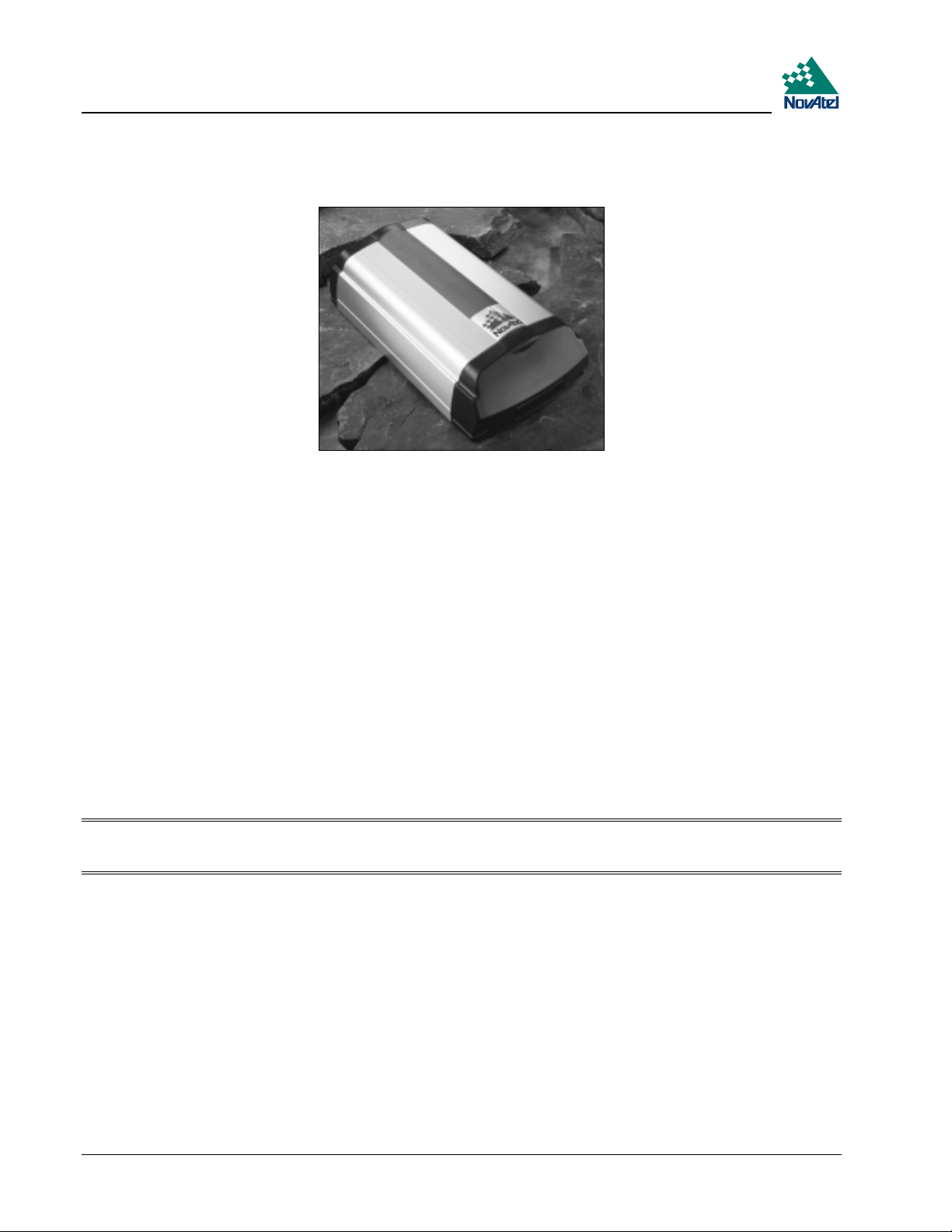
MILLENNIUM GPSCARD
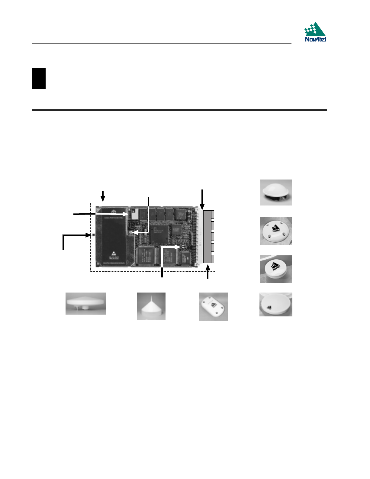
The MiLLennium GPSCard (see Figure 1) consists of a single stand-alone printed circuit board with integrated radiofrequency (RF) and digital sections. It is a high-performance GPS receiver capable of receiving and tracking the L1 C/Acode, L1 and L2 carrier phase, and L2 P-code (or encrypted Y-code) of up to 12 GPS satellites. An active GPSAntenna
is required to function. A dual-frequency antenna is needed for dual-frequency operation, which is possible with some
MiLLennium models. The MiLLennium can be used for both single-point and differential applications.
Figure 1 MiLLennium GPSCard
MiLLennium models with dual-frequency capabilities make the following possible:
longer baselines in differential positioning mode, due to the reduction of atmospheric errors
•
faster resolution of carrier-phase ambiguities when performing RTK positioning
•
enhanced positioning precision due to the additional measurements
•
Patented Narrow Correlator tracking technology circuits combined with a high-performance 32-bit CPU make possible
multipath-resistant processing at high data update rates. Excellent acquisition and re-acquisition times allow this receiver
to operate in environments where very high dynamics and frequent interruption of signals can be expected.
The MiLLennium is fabricated in a "Eurocard" printed circuit board format, utilizing surface-mount manufacturing
technology. After integration with a user-supplied 5V DC power source, a mounting structure, an external antenna, and
I/O data communications equipment, the MiLLennium is ready for the most demanding surveying, positioning, or
navigation applications. It is engineered to provide years of reliable operation.
The MiLLennium offers the OEM developer unparalleled flexibility in areas such as configuration and in the
specification of output data and control signals. The available selection of OEM models is based on a common building
block, allowing you to fit the receivers more exactly to the application while maintaining the option for a compatible
upgrade path.
The following accessories are available from NovAtel Inc. They are designed to make system integration a faster, less
expensive and more reliable task:
• Single or dual-frequency GPSAntenna models (survey, aviation, or DGPS reference station with choke-ring ground
plane)
• Coaxial and power cables
• PowerPak II (enclosure, power supply and I/O connectors)
MiLLennium GPSCard and Enclosures Guide to Installation & Operation 9
Page 10

1 Introduction
ProPak II (enclosure, power supply and I/O connectors)
•
The MiLLennium hardware platform supports several different firmware models and configurations. Some possible
configurations are:
L1-only
•
L1/L2
•
L1 plus WAAS
•
L1/L2 plus WAAS
•
L1 plus RT-20
•
L1/L2 plus RT-2
•
The features common to all MiLLenniums are summarized in Table 1. The functionality of the software is described in
the MiLLennium Command Description Manual. There you will also find listings of all data formats and positioning
modes supported by the MiLLenium receiver.
Table 1 Common Feature Summary - MiLLennium Models
General
2.5-bit sampling
Narrow Correlator tracking technology
Dual serial ports
“EuroCard” printed circuit board format
Fast re-acquisition
Field-programmable for software upgrades
Port for an optional external clock
Five I/O and timing strobes
10 MiLLennium GPSCard and Enclosures Guide to Installation & Operation
Page 11
1 Introduction
For some applications, the MiLLennium PowerPak II and ProPak II are ideal. These are enclosure kits that come
complete with mounting and wiring interfaces, and allow immediate operation of the MiLLennium. The ProPak II is
designed for rugged operating environments, while the PowerPak II is designed for use under normal conditions.
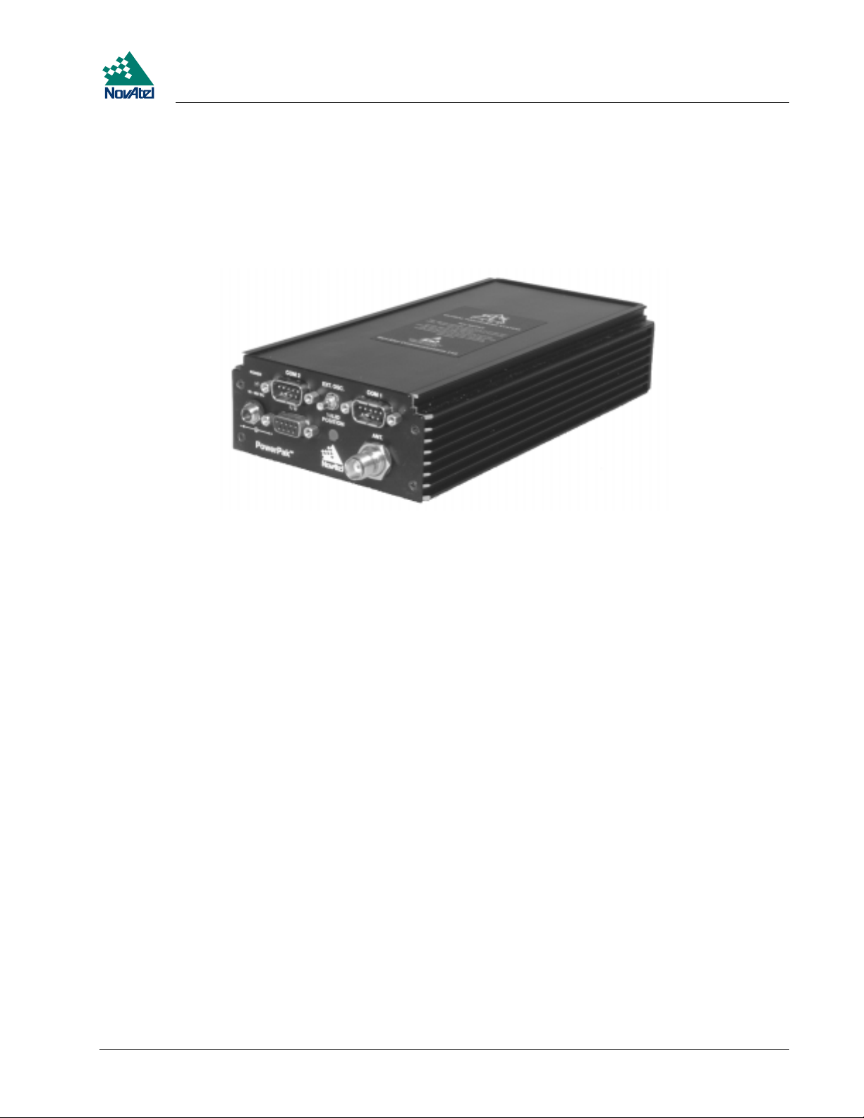
POWERPAK II
The NovAtel PowerPak II provides a hardware interface between your equipment and the NovAtel MiLLennium
GPSCard. When connected to an antenna and a power source, the PowerPak II and MiLLennium together form a fully
functioning GPS receiver. This is only one possible application of the PowerPak II; it can also be used by a system
integrator to test and evaluate MiLLennium GPSCards.
The PowerPak II is intended for stationary operation in benign surroundings such as those found in a laboratory or on a
test bench; it is not designed for environments which feature vibration, dust, moisture or extremes of temperature.
The PowerPak II has these features:
a mounting enclosure complete with a power converter and PCB interconnect back plane
•
GPSolution, NovAtel’s graphical user-interface program, and on-line help
•
an external automotive cigarette-lighter power adapter
•
two serial-data communication ports
•
an input/output port for strobe signals
•
an input port to which an external power source (+10 to +36 V DC) can be connected
•
an input port to which an external, GPSAntenna can be connected
•
an input port to which an external oscillator (5 MHz or 10 MHz) can be connected
•
a RS232C Y-type null-modem cable to facilitate communications with a PC
•
• an electrostatic discharge (ESD) wrist grounding strap
Card guides located inside the mounting enclosure hold the MiLLennium in place; it fits into the second slot from the top
of the enclosure. It couples to the back plane by means of a 64-pin connector.
The PowerPak II is intended to be used with the following NovAtel accessories and options:
• Model 502, 503, or 512 GPSAntenna - dual-frequency, active antennas designed for high-accuracy applications
• Model C005, C015, or C030 (5, 15 or 30 m length) coaxial cable - to connect the GPSAntenna to the PowerPak II
• GPS-APWR - an AC to DC power converter
For those who have purchased a MiLLennium and PowerPak II enclosure separately, a minor procedure is required to
install the MiLLennium and connect a ground wire and two coaxial interconnect cables. This is described in Appendix C,
Page 47.
MiLLennium GPSCard and Enclosures Guide to Installation & Operation 11
Page 12
1 Introduction
PROPAK II
The NovAtel ProPak II is a rugged, reliable enclosure for adverse environments.
The ProPak II has these features:
rugged shock, water, and dust-resistant enclosure constructed of extruded aluminum sealed by two end-caps.
•
two serial communication ports and a strobe port
•
optional mounting plate
•
one straight and one null-modem serial data cable
•
one I/O strobe cable
•
one 4-pin LEMO plug connector to cigarette-lighter plug with built-in 3-amp fuse
•
NovAtel’s GPSolution graphical user interface software
•
The ProPak II is intended to be used with the following NovAtel accessories and options:
Model 502, 503, or 512 GPSAntenna - dual-frequency, active antennas designed for high-accuracy applications
•
Model C005, C015, or C030 (5, 15 or 30 m length) coaxial cable - to connect the GPSAntenna to the ProPak II
•
4-pin LEMO plug connector to 4-pin LEMO plug connector (NovAtel part number: 01016724 [33.5 cm] or
•
01016725 [0.75 cm])
Model GPS-APRO Auto-ranging AC/DC converter and power cables
•
Note: The unit is sealed to provide protection against adverse environmental conditions; therefore, any attempt to
open the case will impair the water-resistant qualities of the enclosure, and void the warranty.
12 MiLLennium GPSCard and Enclosures Guide to Installation & Operation
Page 13
2 Hardware Configuration
2HARDWARE CONFIGURATION
2 HARDWARE CONFIGURATION
MILLENNIUM GPSCARD
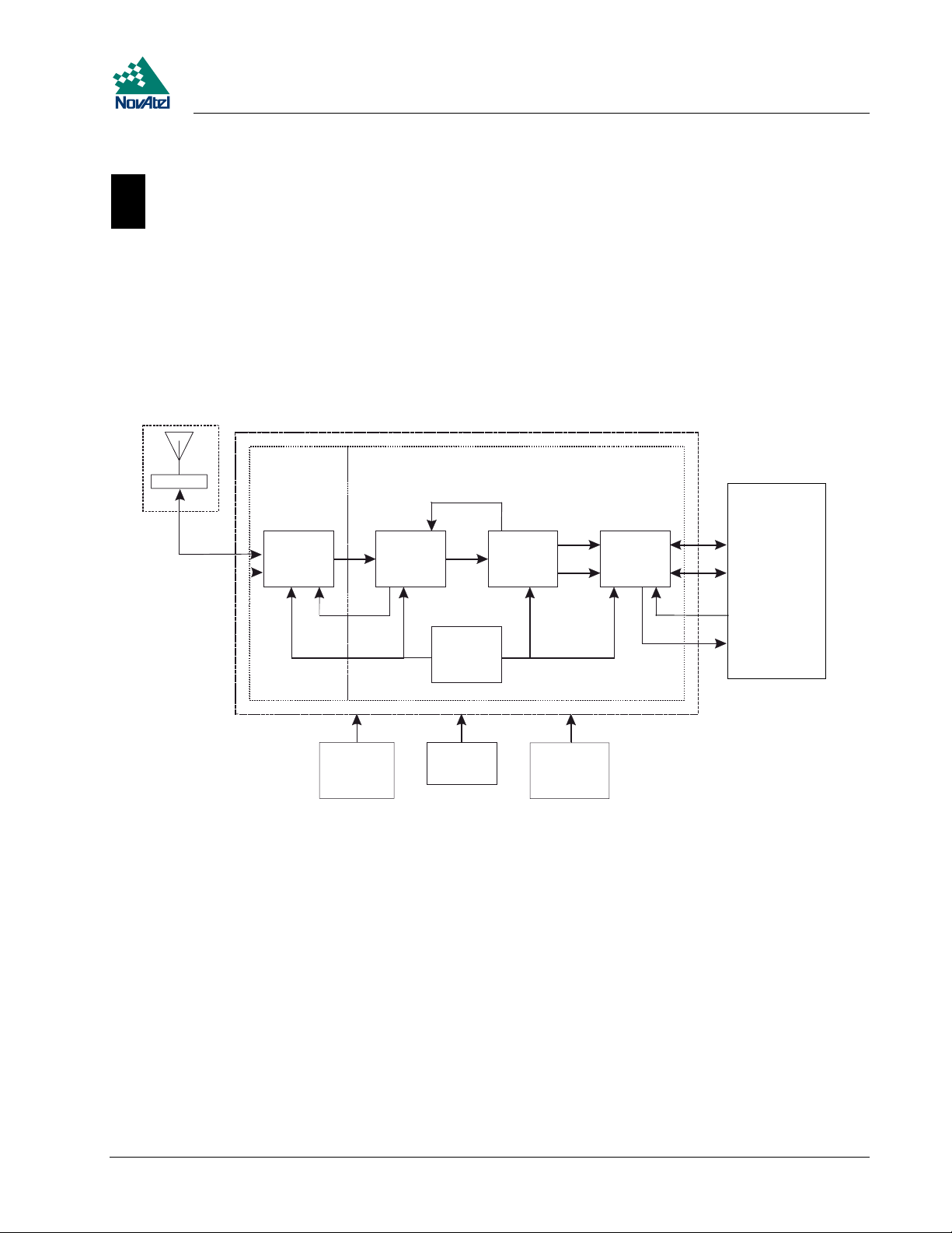
The MiLLennium consists of a radio-frequency (RF) and a digital electronics section. Prior to operation, an antenna,
power supply, and data and signal interfaces must be connected. The overall system is represented in Figure 2.Abrief
description of each section follows.
Figure 2 MiLLennium System Functional Diagram
1
4
18
2
21
3
8
23
22
14 15
20
19
5
13
6
16
19
7
17
Reference Description Reference Description
1 MiLLennium L1/L2 GPSCard 13 VCTCXO
2 RF section 14 RF-IF sections
3 Digital section 15 Signal processor
4 NovAtel GPSAntenna or user-supplied 16 32-bit CPU
5 Optional user-supplied LNA power (0-30 VDC) 17 System I/O
6 User-supplied power (5 VDC) 18 LNA
7 Optional external oscillator (5 or 10 MHz) 19 Clock signals
8 User-supplied data & signal processing equipment 20 AGC signals
9 COM1 21 Control signals
10 COM2 22 RF and power connectors
11 Input timing strobe 23 Antenna feed
12 Output timing strobe
9
10
11
12
MiLLennium GPSCard and Enclosures Guide to Installation & Operation 13
Page 14

2 Hardware Configuration
ANTENNA
The purpose of the antenna is to convert the electromagnetic waves transmitted by the GPS satellites into RF signals. An
active GPS antenna is required; a hardware provision is provided to select an internal or external DC power supply for the
active GPS antenna.
An active antenna is required because its low-noise amplifier (LNA) boosts the power of the incoming signals to
compensate for the line loss between the antenna and MiLLennium. The allowable cable loss for an active antenna
system is 13.0 dB. Excessive signal degradation will occur if this limit is exceeded and the MiLLennium may not be able
to meet its performance specifications.
NovAtel offers a variety of GPSAntenna models. All use low-profile microstrip technology and include band-pass
filtering and an LNA. The GPSAntenna you choose will depend on your particular application and hardware
configuration:
L1-Only Antenna Models
501 - for surveying applications providing enhanced multipath rejection
•
511 - compact, light and environmentally sealed against rain, ice and lightning strikes
•
521 - delivers optimal performance for airborne, marine and mobile applications
•
531 - for surveying and other kinematic positioning applications
•
L1/L2 Antenna Models
502 - for use in surveying and other kinematic positioning applications (an optional choke-ring ground plane,
•
NovAtel part number A032, is also available for use with this model)
503 - for use with high-performance position-reference stations (features a built-in choke-ring ground plane to
•
minimize the effects of multipath interference)
512 - for installation on aircraft (features aerodynamic styling)
•
Each of these models offers exceptional phase-center stability as well as a significant measure of immunity against
multipath interference. Each one has an environmentally sealed radome.
NovAtel also offers high-quality coaxial cable in standard 5, 15 and 30 m lengths. High quality coaxial cable should be
used because a mismatch in impedance, possible with lower quality cable, produces reflections in the cable that increases
signal loss.
While there may be other coaxial cables and antennas on the market that may also serve the purpose, please note that the
performance specifications of the MiLLennium are guaranteed only when it is used with NovAtel-supplied accessories.
ANTENNA CONSIDERATIONS
Selecting and installing an appropriate antenna system are important steps to make before operating your GPS receiver.
The antenna you choose for your GPS system will depend on the specific positioning application.
The choke-ring ground plane on the GPSAntenna Model 503 will further reduce multipath errors while maintaining a
stable phase center (e.g. during geodetic survey-quality positioning). An optional choke-ring (Model A032) is also
available for GPSAntenna Model 502.
The MiLLennium has been designed to operate with any of the NovAtel GPSAntenna models. Though it is possible to
operate with other GPS antennas, no guarantee is made that the MiLLennium will meet its performance specifications if a
non-NovAtel antenna is used.
When installing the antenna system,
• choose an antenna location that has a clear view of the sky to the horizon so that each satellite above the horizon can
be tracked without obstruction
• the location should also be one that minimizes the effect of multipath. For a discussion on multipath, please refer to
the chapter on “Multipath Elimination Technology” in the MiLLennium Command Descriptions Manual
14 MiLLennium GPSCard and Enclosures Guide to Installation & Operation
Page 15

2 Hardware Configuration
mount the antenna on a secure, stable structure capable of safe operation in the specific environment
•
ANTENNA CABLE CONSIDERATIONS
An appropriate coaxial cable is one that is matched to the impedance of antenna being used, and whose line loss does not
exceed the recommendation of 13 dB. High quality coaxial cable should be used because a mismatch in impedance,
possible with lower quality cable, produces reflections in the cable that increases signal loss. NovAtel offers a variety of
coaxial cables to meet your GPSAntenna interconnection requirements. Your local NovAtel dealer can advise you about
your specific configuration.
NovAtel provides optional coaxial cables in the following lengths:
22 cm interconnect adapter cable (SMB female/TNC bulkhead - female)
•
5 m (Model C005), 15 m (Model C015), or 30 m (Model C030) antenna cable (TNC male/TNC male)
•
Should your application require the use of cable longer than 30 m, contact the NovAtel Customer Service department and
request Application Note APN-003, “Extended-Length Antenna Cable Runs” before you proceed. Application notes may
also be found on the NovAtel website at http://www.novatel.ca.
Any of the GPSAntennas can compensate for up to 13 dB of cable loss; if this limit is exceeded, excessive signal
degradation will occur and the MiLLennium may not be able to meet its performance specifications.
Though it is possible to use other high-quality antenna cables, no guarantee is made that the MiLLennium will meet its
performance specifications if non-NovAtel-supplied coaxial cable is used.
Note: The coaxial cable should be connected to the antenna and MiLLennium before system power is turned on. If
for any reason the cable is disconnected from the antenna or MiLLennium, you must turn off power before
reconnecting the cable. This is to prevent the MiLLennium’s antenna current-limiting circuit from
unnecessarily activating and shutting off power to the GPSAntenna. If this occurs, remove power from the
MiLLennium, wait a few moments, and then apply it again.
PRINCIPAL POWER SUPPLY
A single external 5 V DC power supply is all that is necessary to meet the MiLLennium’s 7.5 W (typical) power
consumption. The power input is reverse-polarity protected.
Note: The MiLLennium will suspend operation if the voltage supplied to it falls outside the input range of 4.875 to 5.25 V DC.
OPTIONAL LNA POWER SUPPLY
The MiLLennium provides power to its GPSAntenna out of the primary 5 V DC input. However, if a different type of
antenna is required that is incompatible with this supply, then you could connect an additional power source (≤30 V DC)
to the MiLLennium. In either case, the power is fed to the antenna through the same coaxial cable used for the RF
signals. See jumper P301 in Chapter 3, I, Figure 3 (Page 18) and Figure 4 (Page 21).
RF SECTION
The MiLLennium receives the partially filtered and amplified GPS signals from the antenna via the coaxial cable. The
RF section does the following:
• filters the RF signals to reduce noise and interference
• down-converts (with further band-limiting) the RF signals to intermediate frequencies (IFs) that are suitable for the
analog-to-digital (A/D) converter in the digital electronics section
• amplifies the signals to a level suitable for the A/D converter in the digital electronics section
• receives an automatic gain control (AGC) input from the digital signal processor (DSP) to maintain the IF signals at
a constant level
MiLLennium GPSCard and Enclosures Guide to Installation & Operation 15
Page 16

2 Hardware Configuration
supplies power to an active antenna through the coaxial cable while maintaining isolation between the DC and RF
•
paths. A hardware jumper configuration is provided to select an internal or external DC power supply for an active
GPS antenna. See jumper P301 in the Chapter 3, I, Figure 3 (on page 18) and Figure 4 (on page 21).
The RF section can reject a high level of potential interference (e.g., MSAT, Inmarsat, cellular phone, and TV subharmonic signals).
DIGITAL ELECTRONICS SECTION
The digital section of the MiLLennium receives down-converted, amplified GPS signals that it digitizes and processes to
obtain a GPS solution (position, speed, direction and time). The digital section consists of an analog-to-digital converter,
a 32-bit 25 MHz system processor, memory, control and configuration logic, signal processing circuitry, serial peripheral
devices, and supporting circuitry. I/O data and timing strobe signals are routed to and from the board via a 64-pin DIN
41612 Type B male connector. Two EIA RS-232C serial communications ports support user-selectable bit rates of 300 115,200 bps, with a default of 9600 bps. The digital section does the following:
converts the IF analog signals to a digital format
•
tracks the codes (C/A & P) and carrier phases of the L1 signals (and L2 signals with the appropriate MiLLennium
•
model) of the satellites in use
performs channel and loop control
•
performs position computation
•
executes navigation software
•
performs database management
•
monitors self-test system status
•
controls diagnostic LEDs: a red one which only lights up to indicate an error condition, and a green one (the
•
“heartbeat”) which blinks on and off at approximately 1 Hz to indicate normal operation.
controls I/O functions
•
The strobe signals are described as follows:
Mark input: this signal provides a time tag to the signal processors, which respond to a falling edge of the signal
•
provided from an external device. It can be enabled by you to provide a precise time and data output event.
Measure output: an output measurement rate which generates an active-periodic signal. This output is also routed to
•
the signal processors, where it provides a trigger for the measurement collection.
Variable-frequency (VARF) output: a user-programmable, variable-frequency pulse train
•
PPS output: a 1 ms pulse repeating at a 1 Hz rate that is used to synchronize the board with external devices.
•
Status output: an output that changes logic states when a valid GPS position is obtained
•
You configure the MiLLennium using special commands. In turn, the MiLLennium presents information to you in the
form of pre-defined logs in a number of formats. In addition, when two MiLLenniums are linked for differential
positioning, the reference and the remote stations can communicate directly through their serial ports.
COMMUNICATION PORTS
The default communications protocol for each port is as follows:
• RS232C
• 9600 bits per second
• no parity
• 8 bits
• 1 stop bit
• no hand shaking
• echo off
16 MiLLennium GPSCard and Enclosures Guide to Installation & Operation
Page 17

2 Hardware Configuration
Note: The GPSCard COMn command can be used to change any of these default settings.
Pin-outs are the same for both serial ports. Both ports utilize standard DE9P connectors. Table 6 Serial Port Pin-Out
Description, Page 50 lists the pin-outs for each serial port configuration.
OPTIONAL USER-SUPPLIED EXTERNAL OSCILLATOR
For certain applications requiring greater precision than what is possible using the on-board 20 MHz, voltage-controlled,
temperature-compensated crystal oscillator (VCTCXO), you may wish to connect the MiLLennium to an external, high-
stability oscillator. This is only possible with a MiLLennium GPSCard on its own or in a PowerPak II enclosure, not if
the MiLLennium GPSCard is in a ProPak II enclosure. The external oscillator can be either 5 MHz or 10 MHz.
MiLLennium has built in clock models for OCXO, rubidium and cesium oscillators. You can also set custom clock model
parameters for other types of oscillators.
The two commands EXTERNALCLOCK and EXTERNALCLOCK FREQUENCY relate to external oscillator
operation, see the Using the EXTERNALCLOCK Commands section below. When a MiLLennium is powered on, the
external oscillator input is disabled. Therefore, if an external oscillator is never used, these commands are not needed.
Installation consists of simply connecting the cable from the external oscillator to connector P301, see Figure 3 (Page 18)
and Figure 4 (Page 21), on the MiLLennium. The MiLLennium does not have to be powered down during this
procedure. If handling the MiLLennium directly, anti-static practices must be observed; please see Appendix A (Page 31)
for details.
On the PowerPak II, connect the coaxial cable from the external oscillator output port to the Ext. Osc. input port (SMB
male jack) on the front panel of the PowerPak II.
Using the EXTERNALCLOCK Commands
The EXTERNALCLOCK command determines whether the MiLLennium uses its own internal temperature-
compensated crystal oscillator, or that of an external oscillator, as a frequency reference. It also sets which clock model is
used for an external oscillator:
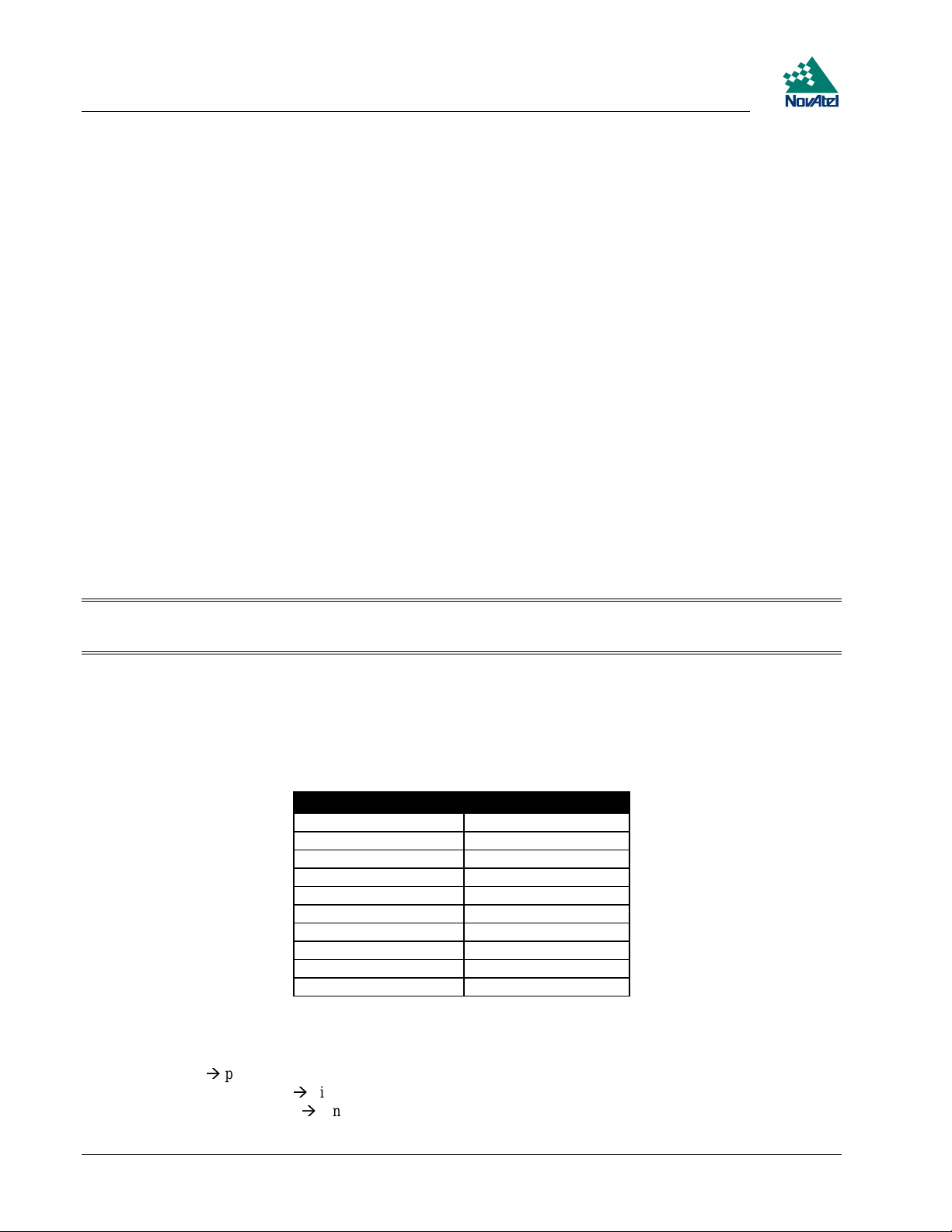
Command Reference Oscillator Clock Model
EXTERNALCLOCK DISABLE Internal
EXTERNALCLOCK OCXO External OCXO
EXTERNALCLOCK CESIUM External Cesium
EXTERNALCLOCK RUBIDIUM External Rubidium
EXTERNALCLOCK CUSTOM External User-defined parameters
The EXTERNALCLOCK DISABLE command forces the MiLLennium to use the internal oscillator, whether or not
there is an external oscillator connected to it. Do not use the EXTERNALCLOCK OCXO, CESIUM, RUBIDIUM or
CUSTOM if there is no external oscillator connected to the MiLLennium.
The EXTERNALCLOCK FREQUENCY command sets the MiLLennium to accept either a 5 MHz or 10 MHz external
oscillator frequency.
Example: externalclock frequency 5
externalclock frequency 10
MiLLennium GPSCard and Enclosures Guide to Installation & Operation 17
Page 18
3 Installation
3I NSTALLATION
3 INSTALLATION
Note: This chapter deals specifically with a bare MiLLennium receiver card. For MiLLenium cards in PowerPak II
and ProPak II enclosures, see Appendices C and D respectively.
The MiLLennium receiver is an OEM product designed for flexibility of integration and configuration. You are free to
select an appropriate data and signal interface, power supply system, and mounting structure. This concept allows OEM
purchasers to custom-design their own GPS-based positioning system around the MiLLennium.
This section provides the necessary information for you to install and begin to use the MiLLennium. A typical system
configuration is shown in Figure 3.
Figure 3 Typical System Configuration
1
3
6
2
5
13
14
4
7
8
9
10
11
12
15
Reference Description Reference Description
1 User-supplied enclosure 9 COM1 (8 pins)
2 RF signal and LNA power; SMB 10 COM2 (8 pins)
connector P201 (male, right-angle)* 11 Input and output timing strobes (12 pins)x
3 External reference clock input; SMB 12 User-supplied interface; matchesitem#4
connector P301 (male, straight) 13 Model 502 GPSAntenna (L1/L2)
4 Power, data & signals connector P1 (male, 14 Model 503 GPSAntenna (L1/L2)
64-pin, 0.1”, DIN 41612, Type B, right-angle) 15 Model 512 GPSAntenna (L1/L2)
5 Status LEDs (green and red) 16 Model 501 GPSAntenna (L1 Only)
6 LNA power jumper P301 (see
7 +5 V DC primary power (2 pins) 18 Model 521 GPSAntenna (L1 Only)
8 Optional LNA; DC power (1 pin) 19 Model 531 GPSAntenna (L 1Only)
* To antenna via interconnecting coaxial cable. High quality coaxial cable should be used because a mismatch in
impedance, possible with lower quality cable, produces reflections in the cable that increases signal loss.
Figure 4, Page 21
) 17 Model 511 GPSAntenna (L1 Only)
16
17
18
19
18 MiLLennium GPSCard and Enclosures Guide to Installation & Operation
Page 19

3 Installation
MINIMUM CONFIGURATION
In order for the MiLLennium to perform optimally, the following additional equipment is required:
NovAtel GPSAntenna (model will depend on application)
•
NovAtel coaxial cable (note that a conversion is required between the male SMB connector on the MiLLennium and
•
the female TNC connector on a GPSAntenna)
A regulated power supply providing +5 V DC (see Appendix B, Page 33) for power regulation specifications)
•
A 64-pin 0.1" DIN 41612 Type B female connector as an interface for power, communications and signals
•
Data communications equipment capable of RS-232C serial communications
•
ANTI-STATIC PRECAUTIONS
Electrostatic discharge (ESD) is a leading cause of failure of electronic equipment components and printed circuit boards
containing ESD-sensitive devices and components. It is imperative that ESD precautions be followed when handling or
installing the MiLLennium printed circuit board. See Appendix A, Page 31 for more information on ESD precautions.
Leave the MiLLennium in its anti-static packaging when not connected in its normal operating environment. When
removing the MiLLennium from the ESD-protective plastic clamshell, follow accepted standard anti-static practices.
Failure to do so may cause damage to the MiLLennium.
When you remove the MiLLennium from the original packing box, it is recommended that you save the box and ESD
protective plastic clamshell for future storage or shipment purposes.
REMEMBER !
Always wear a properly grounded anti-static wrist strap when handling the MiLLennium.
•
Always hold the MiLLennium by its corners or the RF backplane, and avoid direct contact with any of the
•
components.
Do not let the MiLLennium come in contact with clothing at any time because the grounding strap cannot dissipate
•
static charges from fabrics.
Failure to follow accepted ESD handling practices could cause damage to the MiLLennium.
•
Warranty may be voided if equipment is damaged by ESD.
•
INSTALLATION PROCEDURE
Installing the MiLLennium typically consists of the following:
1. mounting the MiLLennium in a secure enclosure to reduce environmental exposure, RF interference, and vibration
effects
2. pre-wiring the I/O harness and the 64-pin DIN female connector for power and communications, then connecting
them to the MiLLennium
3. installing the GPSAntenna, then connecting it to the MiLLennium (see Page 14)
4. installing an optional external oscillator (see Page 17)
MOUNTING THE PRINTED CIRCUIT BOARD
Because the MiLLennium is an OEM product, the printed circuit board is not enclosed in a housing structure. This
allows flexibility in creating a mounting environment to suit particular product and marketing requirements. The
mounting and enclosure must provide the following:
• mounting of external connectors
MiLLennium GPSCard and Enclosures Guide to Installation & Operation 19
Page 20
3 Installation
protection from hostile physical environments (e.g. rain, snow, sand, salt, water, extreme temperatures)
•
protection from vibration conditions
•
electromagnetic shielding to protect from hostile RF environments (e.g. nearby transmitters)
•
electromagnetic shielding so that the final product itself conforms to RF emissions guidelines
•
protection from ESD
•
The MiLLennium card can be held in place by screws, card rails, or both. Please see Appendix B, Page 33 for
mechanical drawings.
PREPARING THE DATA, SIGNAL & POWER HARNESS
The wiring harness provides the following interconnect functions:
access to COM1 and COM2 serial communications ports
•
access to input and output timing strobes
•
power input(s)
•
access to control signals
•
A 64-pin / 0.1" / DIN 41612 / Type B / female connector (e.g. Harting #0902 164 6825, #0902 264 6828, or equivalent)
is required to interface with connector P1 on the MiLLennium (see Figure 3 Typical System Configuration, Page 18).
The connectors you choose for interfacing to the power source(s), COM ports, and strobes will depend on your external
equipment requirements. Appendix E, EDGE-VIEW OF CONNECTOR P1, Page 65 shows the pin names and locations
on connector P1.
Note: See Appendix B, MILLENNIUM TECHNICAL , Page 33 for descriptions of the function of each connector
pin.
A MiLLennium GPSCard can function with the same 64-pin connector built for an OEM2 GPSCard (NovAtel’s second
generation receiver), which makes the upgrade simple. However, an OEM2 GPSCard will not function with a connector
built for a MiLLennium; this is because several pins on the OEM2 GPSCard are no longer used on the MiLLennium, as
shown in Table 2:
Table 2 Disabled OEM2 Connector Pins
OEM2 Signal Name Connector Pin
-12VDC 3A
+12VDC 3B
SELA1 5 B
SELB1 6 B
NMEA Opto 1 7 B
TXD1(-)/NULL 8 B
SELA2 13 B
SELB2 14 B
NMEA Opto 2 15 B
TXD2(-)/NULL 16 B
External Power
See Appendix B, Page 33 for external power input connections:
• Digital ground
• Vcc, main power (+5 V DC)
• Optional external LNA power
pins 1A/B (internally connected)
pins 2A/B (internally connected)
pin 4B (≤ 30 V DC) and 4A (GND)
20 MiLLennium GPSCard and Enclosures Guide to Installation & Operation
Page 21
3 Installation
Note: See Appendix B, Page 33 for specifications concerning external power inputs.
The MiLLennium requires only one regulated power input of Vcc = +5 V DC
It is possible to supply power to the LNA on an active antenna either from the MiLLennium or from an external source.
The MiLLennium is factory-configured for operation with any of the GPSAntenna models, in which case no special
wiring or configuration is required: the P301 jumper (see Figure 4) is normally set for internal operation (pins 1 and 2).
The MiLLennium’s internal antenna power supply can produce 4.25 - 5.25 V DC at up to 90 mA. If the antenna draws
more than 90 mA of current, power to the antenna will be disabled and the antenna self-test status flag set to zero; refer to
the RVSA/B log in the MiLLennium Command Descriptions Manual for self-test status codes.
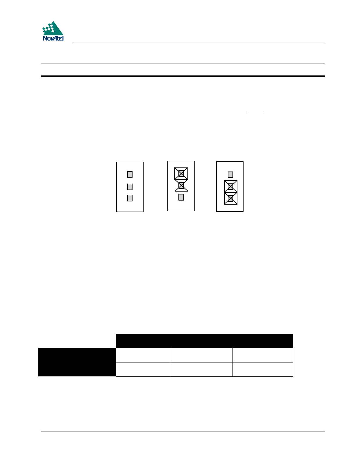
Figure 4 LNA Power Jumper P301–3Cases
456
1
2
1
1
22
33
3
Reference Description
1Pin1
2Pin2
3Pin3
4 Case 1: No power to LNA
5 Case 2: Internal power source (default)
6 Case 3: External power source
If a different antenna is used whose LNA requires voltage and/or current capacity beyond what the MiLLennium can
produce, then the external LNA power option must be utilized - this requires that P301 must be jumpered between pins 2
and 3. The input cannot exceed +30 V DC at 100 mA. When the LNA jumper plug is in the external position, the
antenna sensing circuit will cause the self-test status code to always report antenna status as 1 (good). Refer to the
RVSA/B log in the MiLLennium Command Descriptions Manual for self-test status codes.
If no LNA power required, remove the jumper at P301 completely.
Table 3 Antenna LNA Power Configuration
P301: plug
connects pins 1&2
ANTENNAPOWER = ON internal power
connected to LNA
ANTENNAPOWER = OFF internal power cut
off from LNA
P301: plug connects
pins 2&3
no external effect no external effect
no external effect no external effect
P301: no plug
The setting of this command will also affect the way the MiLLennium’s self-test diagnostics report the antenna’s status;
please refer to the description of the ANTENNAPOWER command in the MiLLennium Command Descriptions Manual.
MiLLennium GPSCard and Enclosures Guide to Installation & Operation 21
Page 22

3 Installation
CAUTION !
The P301 jumper plug must be jumpered to the external position (pins 2 and 3) before external LNA power is
•
connected to pin 4B of the 64-pin wire harness connector to prevent power from feeding back into the receiver.
Should it be necessary, due to an extended-length antenna cable, to supply external power to a GPSAntenna or to use
•
an optional in-line LNA amplifier, be careful not to exceed the voltage ratings of either the antenna or LNA.
No guarantee is made that the MiLLennium will meet its performance specifications if a non-NovAtel antenna is
•
used.
It is recommended that appropriate fuses or current limiting be incorporated as a safety precaution on all power lines
used. Use a sufficient gauge of wire to ensure that the voltage at the 64-pin connector is within the MiLLennium’s
requirements.
RS232C Communications
The MiLLennium is capable of communications in EIA RS232C serial data format via two ports, COM1 and COM2.
See Appendix B, Page 33 for data connections:
COM1
•
COM2
•
Each port has a ground connection, and supports the following signals:
pins 7 - 11, A & B
pins 15 - 19, A & B
Data Terminal Ready (DTR)
•
Clear To Send (CTS)
•
Transmitted Data (TXD)
•
Request To Send (RTS)
•
Received Data (RXD)
•
Data Set Ready (DSR)
•
Data Carrier Detect (DCD)
•
The port settings (bit rate, parity, etc.) are software-configurable. These are further described in Chapter 4.
Note: See Appendix B, Page 33 for further information on data communications characteristics.
Strobe Signals
The MiLLennium has 5 TTL-compatible I/O strobe lines. See Appendix B, Page 33 for strobe signal connections:
Pin 21B
Pin 22B
Variable-Frequency (VARF) Output
•
One Pulse per Second (PPS) Output
•
Measure Output
•
• Mark Input
• Status Output
Note: See Appendix B for further information on I/O strobe characteristics.
Pin 23B
Pin 24B
Pin 25B
22 MiLLennium GPSCard and Enclosures Guide to Installation & Operation
Page 23

4 Operation
4OPERATI ON
4 OPERATION
Before operating the receiver for the first time, ensure that you have followed the installation instructions in Chapter 3.
The following instructions are based on a configuration such as that shown in Figure 5.
Figure 5 Typical Operational Configuration
3
4
10
8
1
11
5
9
2
12
7
Reference Description Reference Description
1 MiLLennium GPSCard 7 Optional external oscillator
2 Enclosure 8 GPS signal
3 GPSAntenna 9 Clock signal
4 Command source or reference station 10 COM1
5 Data logger or remote station 11 COM2
6 External power source 12 Power
6
COMMUNICATIONS WITH THE RECEIVER
Communication with the receiver is straightforward, and consists of issuing commands through the COM1 or COM2 port
from an external serial communications device. This could be either a terminal or an IBM-compatible PC that is directly
connected to a receiver serial port using a null modem cable. For specific information about any of the GPSCard
commands and logs, please consult the MiLLennium Command Descriptions Manual.
It is assumed that a personal computer is used during the initial operation and testing for greater ease and versatility.
Furthermore, it should be understood that communication between the MiLLennium and a computer is achieved by virtue
of the GPS firmware that resides within the MiLLennium.
MiLLennium GPSCard and Enclosures Guide to Installation & Operation 23
Page 24

4 Operation
SERIAL PORT DEFAULT SETTINGS
The receiver communicates with your PC or terminal via the COM1 or COM2 serial port. For communication to occur,
both the receiver and the operator interface have to be configured properly. The receiver’s default port settings are as
follows:
RS232C, 9600 bps, no parity, 8 data bits, 1 stop bit, no handshaking, echo off
•
Changing the default settings requires using the COMn command, which is described in the MiLLennium Command
Descriptions Manual. It is recommended that you become thoroughly familiar with these commands and logs to ensure
maximum utilization of the receiver’s capabilities.
Note: Although the receiver can operate at bit rates as low as 300 bps, this may not always be desirable. For
example, if several data logs are active (i.e. a significant amount of information needs to be transmitted every
second) but the bit rate is set too low, data will overflow the serial port buffers and cause an error condition in
the receiver status.
COMMUNICATING USING A REMOTE TERMINAL
One method of communicating with the receiver is through a remote terminal. The receiver has been pre-wired to allow
proper RS232C interface with your data terminal. To communicate with the terminal the receiver only requires the RX,
TX, and GND lines to be used; handshaking is not required, although it can optionally be used. Ensure that the terminal’s
communications set-up matches the receiver RS232C protocol.
COMMUNICATING USING A PERSONAL COMPUTER
An IBM-compatible PC can be set up to emulate a remote terminal as well as provide the added flexibility of creating
multiple-command batch files and data logging storage files. Any standard communications software package that
emulates a terminal can be used to establish bi-directional communications with the receiver.
One can create command batch files using any text editor; these can then be directed to the serial port that is connected to
the receiver using a communications software package. This is discussed in greater detail later in this chapter.
GETTING STARTED
Included with your receiver are NovAtel’s GPSolution and Convert programs, together with their user documentation.
GPSolution is a Microsoft Windows-based graphical user interface that allows you to access the receiver's many features
without struggling with communications protocol or writing special software. GPSolution automatically recognizes the
model of receiver that you are using and adjusts the displays accordingly. Figure 6 shows a sample GPSolution screen.
The Convert utility is a Windows-based utility that allows you to convert between file formats, and strips unwanted
records for data file compilation.
24 MiLLennium GPSCard and Enclosures Guide to Installation & Operation
Page 25

Figure 6 Sample GPSolution Screen
4 Operation
GPSolution is provided to facilitate your interaction with the receiver. However, it certainly is possible to communicate
with it through DOS or a Windows-based communications program; this is discussed in greater detail later in this section.
POWER ON
The receiver’s software resides in read-only memory. As such, the unit “self-boots” upon power-up and undergoes a
complete self-test. If an error condition is detected during a self-test, the self-test status word would change; this self-test
status word can be viewed in the RGEA/B/D and RVSA/B data output logs (please refer to the MiLLennium Command
Descriptions Manual). If a persistent error develops, please contact NovAtel Customer Service.
When the receiver is first powered up, no activity information is transmitted from the COM ports except for the port
prompt; the external data communications equipment screen will display one of these two messages:
Com1> if connected to COM1 port,
or
Com2> if connected to COM2 port
Either prompt indicates that the receiver is ready and waiting for command input.
Commands are typed at the interfacing terminal’s keyboard, and sent after pressing the terminal’s Return or Enter key.
Note: Most valid commands do not echo a response to a command input; the indication that they have been accepted
is a return of the port prompt from the receiver. VERSION, HELP and ? are the only commands that do
provide a data response other than the port prompt.
MiLLennium GPSCard and Enclosures Guide to Installation & Operation 25
Page 26

4 Operation
Example:
An example of no echo response to an input command is the FIX HEIGHT command. It can be entered as follows:
COM2>fix height 550 [Return]
COM2>
The above example illustrates command input to the receiver COM1 port which sets the receiver antenna height as fixed
to 550 m above sea level and causes position solutions to be constrained as 2D with height fixed. However, your only
confirmation that the command was actually accepted is the return of the COM2> prompt.
If a command is incorrectly entered, the receiver will respond with “Invalid Command Name” (or a more detailed error
message) followed by the port prompt.
After initial boot up, you may find the following logs useful for observing the receiver activities. While GPSolution is
the easiest way to do this, you can also use DOS or a Windows-based communications program; examples of both are
provided below.
Use the RCCA log to list the default command settings. After the receiver has been operational for a while, the
•
RCCA log will be useful for indicating status of all current command settings. Displaying the RCCA log after a
RESET will show the saved configuration (refer to the SAVECONFIG command in the MiLLennium Command
Descriptions Manual for more information).
Use the ETSA log to monitor the channel tracking status.
•
Use the SATA log to observe the satellite specific data.
•
Use the POSA log to observe the current computed position solutions.
•
Use the DOPA log to monitor the dilution of precision of the current satellite constellation.
•
Use the RVSA log to monitor the receiver status.
•
Use the HELP command to list all available commands.
•
Use the HELP LOG command to list all available logs.
•
Refer to the MiLLennium Command Descriptions Manual for procedures and explanations related to data logging.
DOS
One way to initiate multiple commands and logging from the receiver is to create DOS boot-up command files relating to
specific functions. This will save time when you want to duplicate test situations and minimize set-up time. Any
convenient text editor can be used to create command text files.
Example:
For this example, consider a situation where a PC’s appropriately-configured COM1 port is connected to the receiver’s
COM1 port, and where a remote terminal is connected to the receiver’s COM2 port. The PC user wishes to monitor the
receiver’s activity; the following command file could be used to do this.
1. Open a text editor on the PC and type in the following command sequences:
log com2 sata ontime 15
log com2 etsa ontime 15
log com2 rvsa ontime 60 5
log com2 posa ontime 15
log com2 dopa ontime 15
2. Save this with a convenient file name (e.g. C:\GPS\BOOT1.TXT) and exit the text editor.
3. Use the DOS copy command to direct the contents of the BOOT1.TXT file to the PC’s COM1 port:
26 MiLLennium GPSCard and Enclosures Guide to Installation & Operation
Page 27

4 Operation
C:\GPS>copy boot1.txt com1
1 files(s) copied
C:\GPS>
4. The receiver is now initialized with the contents of the BOOT1.TXT command file, and logging is directed from
the receiver’s COM2 port to the remote terminal.
MICROSOFT WINDOWS 3.1 OR HIGHER
As any text editor or communications program can be used for these purposes, the use of Windows 95 is described only
as an illustration. The following example shows how Windows 95 accessory programs Notepad and HyperTerminal can
be used to create a hypothetical waypoint navigation boot-file on a PC, and send it to the receiver. It is assumed that the
PC’s serial port COM1 is connected to the receiver’s COM1 port, and that a remote terminal is connected to the
receiver’s COM2 port.
Example:
1. Open Notepad and type in the following command text:
setnav 51.111 -114.039 51.555 -114.666 0 start stop
magvar -21
log com1 posa ontime 15
log com1 spha ontime 15
log com1 nava ontime 15
log com2 gprmb ontime 15 5
log com2 gpvtg ontime 15 5
log com2 rcca ontime 60
2. Save this with a convenient file name (e.g. C:\GPS\BOOTNAV1.TXT) and exit Notepad.
3. Ensure that the HyperTerminal settings are correctly set up to agree with the receiver communications
protocol; these settings can be saved (e.g. C:\GPS\OEMSETUP.HT) for use in future sessions. You may wish to
use XON / XOFF handshaking to prevent loss of data.
4. From the Transfer menu, use the Send text file selection to locate this file to be sent to the receiver. Once you
double-click on the file or select Open, HyperTerminal will send the file to the receiver.
The above example initializes the receiver with origin and destination waypoint coordinates and sets the magnetic
variation correction to -21 degrees. The POSA, SPHA, and NAVA logs have been set to output from the receiver COM1
port at intervals of once every 15 seconds, whereas the GPRMB and GPVTG NMEA logs have been set to be logged out
of the receiver COM2 port at intervals of 15 seconds and offset by five seconds. The RCCA log has been set to output
every 60 seconds from the receiver COM2 port.
MiLLennium GPSCard and Enclosures Guide to Installation & Operation 27
Page 28

5 Firmware Upgrades & Updates
5FIRM WAREUPGRADES & UPDATES
5 FIRMWARE UPGRADES & UPDATES
The MiLLennium stores its program firmware in non-volatile memory, which allows you to perform firmware upgrades
and updates without having to return the MiLLennium to the distributor. New firmware can be transferred to the
MiLLennium through a serial port, and the unit will immediately be ready for operation at a higher level of performance.
The first step in upgrading your receiver is to contact your local NovAtel dealer. Your dealer will assist you in selecting
the best upgrade option that suits your specific GPS needs. If your needs are still unresolved after seeing your dealer then
you can contact NovAtel directly through any of the methods described in the Customer Service section, Page 6,atthe
beginning of this manual.
When you call, be sure to have available your MiLLennium model number, serial number, and program revision level.
This information is printed on the original shipping box as well as on the back side of the MiLLennium itself. You can
also verify the information by issuing the VERSION command at the port prompt.
After establishing which new model/revision level would best suit your needs, and having described the terms and
conditions, you will be issued with an authorization code (auth-code). The auth-code is required to unlock the new
features according to your authorized upgrade/update model type.
There are two procedures to choose from, depending on the type of upgrade/update you require:
1. If you are upgrading to a higher performance model at the same firmware revision level (e.g. upgrading from a
MiLLennium Standard rev. 4.50, to a MiLLennium RT-2 rev. 4.50), you can use the $AUTH special command.
2. If you are updating to a higher firmware revision level of the same model (e.g. updating a MiLLennium Standard
rev. 4.45 to a higher revision level of the same model, such as MiLLennium Standard rev. 4.50), you will need to
transfer new program firmware to the MiLLennium using the Loader utility program. As the Loader and update
programs are generally provided in a compressed file format, you will also be given a file decompression password.
The Loader and update files can be found on NovAtel’s FTP site at http:\\www.novatel.ca, or can be sent to you on
floppy disk or by e-mail.
Your local NovAtel dealer will provide you with all the information that you require to update or upgrade your receiver.
UPGRADING USING THE $AUTH COMMAND
The $AUTH command is a special input command which authorizes the enabling or unlocking of the various model
features. Use this command when upgrading to a higher performance MiLLennium model available within the same
revision level as your current model (e.g., upgrading from a MiLLennium Standard rev. 4.50, to a MiLLennium RT-2
rev. 4.50). This command will only function in conjunction with a valid auth-code assigned by GPS Customer Service.
The upgrade can be performed directly from Loader’s built-in terminal emulator, GPSolution’s Command Line Screen,
or from any other communications program. The procedure is as follows:
1) Power-up the MiLLennium and establish communications over a serial port (see Chapter 4, O, Page 23)
2) Issue the VERSION command to verify the current firmware model number, revision level, and serial number.
3) Issue the $AUTH command, followed by the auth-code and model type. The syntax is as follows:
Syntax:
$auth auth-code
28 MiLLennium GPSCard and Enclosures Guide to Installation & Operation
Page 29

5 Firmware Upgrades & Updates
where
$auth is a special command which allows program model upgrades
auth-code is the upgrade authorization code, expressed as hhhh,hhhh,hhhh,hhhh,hhhh,model# where the
h characters are an ASCII hexadecimal code, and the model# would be ASCII text
Example:
$auth 17cb,29af,3d74,01ec,fd34,millenrt2
Once the $AUTH command has been executed, the MiLLennium will reboot itself. Issuing the VERSION command
will confirm the new upgrade model type and version number.
UPDATING USING THE LOADER UTILITY
Loader is required (instead of the $AUTH command) when updating previously released firmware with a newer version
of program and model firmware (e.g., updating a MiLLennium Standard rev. 4.45 to a higher revision level of the same
model, such as MiLLennium Standard rev. 4.50). Loader is a DOS utility program designed to facilitate program and
model updates. Once Loader is installed and running, it will allow you to select a host PC serial port, bit rate, directory
path, and file name of the new program firmware to be transferred to the MiLLennium.
TRANSFERRING FIRMWARE FILES
To proceed with your program update, you must first acquire the latest firmware revision. You will need a file with a
name such as OEMXYZ.EXE (where XYZ is the firmware revision level). This file is available from NovAtel’s FTP
site (http:\\www.novatel.ca), or via e-mail (support
you on floppy disk. For more information on how to contact NovAtel Customer Service please see Page 6 at the
beginning of this manual.
You will need at least 1 MB of available space on your hard drive. For convenience, you may wish to copy this file to a
GPS sub-directory (e.g., C:\GPS\LOADER).
The file is available in a compressed format with password p rotection; Customer Service will provide you with the
required password. After copying the file to your computer, it must be decompressed. The syntax for decompression is
as follows:
Syntax:
[filename]-s[password]
where
filename is the name of the compressed file (but not including the .EXE extension)
-s is the password command switch
password is the password required to allow decompression
Example:
oem442 -s12345678
The self-extracting archive will then generate the following files:
@novatel.ca). If transferring is not possible, the file can be mailed to
• LOADER.EXE Loader utility program
• LOADER.TXT Instructions on how to use the Loader utility
• XYZ.BIN Firmware version update file, where XYZ = program version level (e.g. 442.BIN)
MiLLennium GPSCard and Enclosures Guide to Installation & Operation 29
Page 30

5 Firmware Upgrades & Updates
USING THE LOADER UTILITY
The Loader utility can operate from any DOS directory or drive on your PC. The program is comprised of three parts:
Program Card (authorization procedure), Setup (communications configuration) and Terminal (terminal emulator). The
main screen is shown in Figure 7.
Figure 7 Main screen of LOADER program
If you are running Loader for the first time, be sure to access the Setup menu (step 3 below) before proceeding to
Program Card (step 4 below); otherwise, you can skip step 3. The procedure is as follows:
1. Turn off power to the MiLLennium.
2. Start the Loader program.
3. From the main menu screen, select Setup to configure the serial port over which communication will occur
(default: COM1) , and the data transfer rates for both programming (default: 115 200 bits per second) and terminal
emulation (default: 9600 bps). To minimize the time required, select the highest serial bit rate your PC can reliably
support. Loader will verify and save your selections in a file named LOADER.SET, and return to the main menu
screen.
4. From the main screen, select Program Card.
5. Select the disk drive (e.g., A, B, C, D) in which the update file (e.g. 442.BIN) is located. Select the path where the
update program file is located (e.g., C:\GPS\LOADER
path. Select the required update file (e.g. 442.BIN).
6. At the prompt, enter your update auth-code (e.g. 17b2,32df,6ba0,92b5,e5b9,millenrt2).
7. When prompted by the program, turn on power to the MiLLennium. Loader will automatically establish
communications with the MiLLennium. The time required to transfer the new program data will depend on the bit
rate, which was selected earlier.
8. When the transfer is complete, use a terminal emulator such as that in Loader (select Terminal) to issue the
VERSION command; this will verify your new program version number. When using the terminal emulator in
Loader, a prompt does not initially appear; you need to enter the command first, which then produces a response,
after which a prompt will appear.
); the directory from which you started
Loader is the default
9. Exit Loader (select Quit).
This completes the procedure required for field-updating a MiLLennium.
30 MiLLennium GPSCard and Enclosures Guide to Installation & Operation
Page 31

A Anti-Static Practices
AANTI -STATICPRACTI CES
A ANTI-STATIC PRACTICES
OVERVIEW
Static electricity is electrical charge stored in an electromagnetic field or on an insulating body. This charge can flow as
soon as a low-impedance path to ground is established. Static-sensitive units can be permanently damaged by static
discharge potentials of as little as 40 volts. Charges carried by the human body, which can be thousands of times higher
than this 40 V threshold, can accumulate through as simple a mechanism as walking across non-conducting floor
coverings such as carpet or tile. These charges may be stored on clothing, especially when the ambient air is dry, through
friction between the body and/or various clothing layers. Synthetic materials accumulate higher charges than natural
fibers. Electrostatic voltage levels on insulators may be very high, in the order of thousands of volts.
Various electrical and electronic components are vulnerable to electrostatic discharge (ESD). These include discrete
components, hybrid devices, integrated circuits (ICs), and printed circuit boards (PCBs) assembled with these devices.
RECOMMENDATIONS FOR HANDLING ESD-SENSITIVE DEVICES
ESD-sensitive devices must only be handled in static-controlled locations. Some recommendations for such handling
practices follow:
Handling areas must be equipped with a grounded table, floor mats, and wrist or ankle straps.
•
A relative humidity level must be maintained between 20% and 80% non-condensing.
•
No ESD-sensitive board or component should be removed from its protective package, except in a static-controlled
•
location.
A static-controlled environment and correct static-control procedures are required at both repair stations and
•
maintenance areas.
ESD-sensitive devices must be handled only after personnel have grounded themselves via wrist or ankle straps and
•
mats.
Boards or components should never come in contact with clothing, because normal grounding cannot dissipate static
•
charges on fabrics.
A circuit board must be placed into an anti-static plastic clamshell before being removed from the work location and
•
must remain in the clamshell until it arrives at a static-controlled repair/test center.
Circuit boards must not be changed or moved needlessly. Handles or finger holes may be provided on circuit boards
•
for use in their removal and replacement; care should be taken to avoid contact with the connectors and components.
On-site repair of ESD-sensitive equipment should not be undertaken except to restore service in an emergency where
•
spare boards are not available. Under these circumstances repair station techniques must be observed. Under normal
circumstances a faulty or suspect circuit board must be sent to a repair center having complete facilities, or to the
manufacturer for exchange or repair.
• Where protective measures have not been installed, a suitable alternative would be the use of a Portable Field Service
Grounding Kit. This consists of a portable mat and wrist strap which must be attached to a suitable ground.
• A circuit board in a static-shielding bag or clamshell may be shipped or stored in a cardboard carton, but the carton
must not enter a static-controlled area such as a grounded or dissipative bench top or repair zone. Do not place
anything else inside the bag (e.g. repair tags).
• Treat all PCBs and components as ESD sensitive. Assume that you will damage the PCB or component if you are
not ESD conscious.
• Do not use torn or punctured static-shielding bags. A wire tag protruding through the bag could act as a “lightning
rod”, funneling the entire charge into the components inside the bag.
• Do not allow chargeable plastics , such as binders, within 0.6 m of unshielded PCBs.
• Do not allow a PCB to come within 0.3 m of a computer monitor.
MiLLennium GPSCard and Enclosures Guide to Installation & Operation 31
Page 32

A Anti-Static Practices
PRIME STATIC ACCUMULATORS
Table 4 provides some background information on static-accumulating materials.
Table 4 Prime Static Accumulators
Work Surfaces • formica (waxed or highly resistive)
• finished wood
• synthetic mats
• writing materials, note pads, etc.
Floors • wax-finished
•vinyl
Clothes • common cleanroom smocks
• personal garments (all textiles except virgin wool)
• non-conductive shoes
Chairs • finished wood
•vinyl
• fiberglass
Packing and handling • common polyethylene bags, wraps, envelopes, and bubble pack
• pack foam
• common plastic trays and tote boxes
Assembly, cleaning, test and
repair areas
• spray cleaners
• common solder sucker
• common solder irons
• common solvent brushes (synthetic bristles)
• cleaning, drying and temperature chambers
HANDLING PRINTED CIRCUIT BOARDS
ESD damage to unprotected sensitive devices may occur at any time. ESD events can occur far below the threshold of
human sensitivity. Follow this sequence when it becomes necessary to install or remove a c ircuit board:
1. After you are connected to the grounded wrist strap, remove the circuit board from the frame and place it on a staticcontrolled surface (grounded floor or table mat).
2. Remove the replacement circuit board from the static-shielding bag or clamshell and insert it into the equipment.
3. Place the original board into the shielding bag or clamshell and seal it with a label.
4. Do not put repair tags inside the shielding bag or clamshell.
5. Disconnect the wrist strap.
32 MiLLennium GPSCard and Enclosures Guide to Installation & Operation
Page 33

B MiLLennium Technical Specifications
BMI LLENNIUMTECHNI CALSPECIFI CATIONS
B MILLENNIUM TECHNICAL SPECIFICATIONS
PHYSICAL
Size
Weight 175 grams
100.00 x 179.9 x 14.7 mm with connector; Eurocard format
MECHANICAL DRAWINGS
Figure 8 MiLLennium Board Dimensions
Units: millimeters [inches]
MiLLennium GPSCard and Enclosures Guide to Installation & Operation 33
Page 34

B MiLLennium Technical Specifications
MECHANICAL DRAWINGS (CONTINUED)
Figure9 L1/L2SeriesSide&EndViews
Units: millimeters [inches]
ENVIRONMENTAL
Operating Temperature -40° C to +85° C
Storage Temperature -45°C to +95°C
Humidity 95% non-condensing (max.)
Altitude Sea level to 5000 m [ may operate above 5000 m in a controlled environment,
however is not certified as such ]
34 MiLLennium GPSCard and Enclosures Guide to Installation & Operation
Page 35

B MiLLennium Technical Specifications
VIBRATION (Random Profile)
The MiLLennium will acquire and track satellites while undergoing vibration levels as shown below. This assumes that
it is mounted using full-length clamped rail mounts and that no vibrating object i s touching it. It also assumes that
C/No> 45 dB-Hz and that the MiLLennium is in high-dynamicsmode. Although not all MiLLennium GPSCards
conform to random vibration templates for RTCA/DO-160C, Section 8.6.2 (Curve C template), MIL-STD-202F, Test
Condition I (Letter A nominal template), and ASAE EP455, Section 5.15.1 nominal template, many do. It is possible to
purchase a pre-screened MiLLennium GPSCard to meet these vibration requests if required. Please consult NovAtel
Customer Service for further information. Note that a MiLLennium GPSCard in a PowerPak II or ProPak II enclosure
does conform.
Frequency < 10 Hz 10 Hz 40 Hz 1000 Hz 2000 Hz > 2000 Hz
Magnitude (g2/Hz)
Typical Mounting Configuration - Mount the GPSCard securely using screws driven through the card’s four corner
mounting holes.
Superior Mounting Configuration - Mount the card using full length clamped rail mounts.
Note: The card is sensitive to any external vibration against it.
+ 80 dB/decade 0.00125 0.02 0.02 0.005 - 80 dB/decade
ACCELERATION
Acceleration 6g maximum (sustained tracking)
POWER REQUIREMENTS
Voltage 4.875 - 5.250 V DC
Allowable voltage ripple 75 mV p-p (max.)
Power 6.75 W (typ.), 7.5 W (max.)
POWER & DATA CONNECTOR ON THE MILLENNIUM
Connector on MiLLennium 64 pin 0.1" DIN 41612 Type B male right-angle
EXTERNAL CLOCK INPUT ON THE MILLENNIUM
Connector on MiLLennium SMB male jack
External Clock Input Frequency: 5 MHz or 10 MHz CW
Input Impedance: 50 Ω nominal
Input VSWR: 2.0:1
Signal Level: 4.0 dBm minimum to 10.0 dBm maximum
Freq. stability: ±0.5 ppm maximum
RF Input / LNA Power Output
Connector on MiLLennium SMB right-angle male jack
RF Input 1575.42 MHz, 1227.60 MHz
LNA Power Output
Internal
External
LNA power output is determined by the LNA jumper plug P301 position
(internal/external)
4.25 - 5.25 V DC @ 0 - 90 mA (current limit 120 ± 30 mA)
≤ 30 V DC, 100 mA max. (user-supplied)
MiLLennium GPSCard and Enclosures Guide to Installation & Operation 35
Page 36

B MiLLennium Technical Specifications
MiLLen-3151R Performance
Position Accuracy Standalone
SA off 15 m CEP
SA on 40 m CEP
Code differential 0.75 m CEP
Post Processed ±5mm+1ppm
Time To First Fix Cold start 70 s (typical)
Reacquisition Warm start 1 s (typical)
Data Rates Raw measurement 20 Hz
Computed position 10 Hz
Time Accuracy SA off 50 ns RMS
SA on 250 ns RMS
Velocity Accuracy Standalone 0.20m/s RMS
Differential 0.03 m/s RMS
Measurement Precision C/A code phase 10 cm RMS
Carrier phase
Dynamics Acceleration 6 g
Velocity 515 m/s max.
MiLLen-3151W Performance
(Subject To GPS System Characteristics)
Single channel 3 mm RMS
Differential channel 0.75 mm RMS
(Subject To GPS System Characteristics)
GPS Only GPS + WAAS
Position Accuracy Standalone:SA on 42 m CEP 3.2 m CEP
Differential: Code (RTCA/RTCM) 0.75 m CEP 0.75 m CEP
Time To First Fix Cold start 70 s (typical) 70 s
Reacquisition Warm start 1 s (typical) 3 s
Data Rates Raw measurement 20 Hz 2 Hz
Computed position 10 Hz 2 Hz
Time Accuracy SA off (RMS) 50 ns 50 ns
SA on (RMS) 250 ns 50 ns
Velocity Accuracy Standalone (RMS) 0.20 m/s 0.20 m/s
Differential (RMS) 0.03 m/s 0.03 m/s
Measurement Precision C/A code phase (RMS) 10 cm 10 cm
Carrier phase
Single channel (RMS) 3 mm 3 mm
Differential channel (RMS) 0.75 mm 0.75 mm
Dynamics Acceleration 6g 6g
Velocity 515 m/s max. 515 m/s max.
36 MiLLennium GPSCard and Enclosures Guide to Installation & Operation
Page 37

B MiLLennium Technical Specifications
MiLLen-RT20 Performance
Position Accuracy Standalone
SA off 15 m CEP
SA on 40 m CEP
Code differential 0.75 m CEP
RT-20 differential 0.20 m CEP
Post Processed ±5mm+1ppm
Time To First Fix Cold start 70 s (typical)
Reacquisition Warm start 1 s (typical)
Data Rates Raw measurement 20 Hz
Computed position 10 Hz
Time Accuracy SA off 50 ns RMS
SA on 250 ns RMS
Velocity Accuracy Standalone 0.20 m/s RMS
Differential 0.03 m/s RMS
Measurement Precision C/A code phase 10 cm RMS
Carrier phase:Single channel 3 mm RMS
Dynamics Acceleration 6 g
Velocity 515 m/s max.
MiLLen-RT2 Performance
Position Accuracy Standalone
SA off 15 m CEP
SA on 40 m CEP
Differential
Code (L1, C/A) 0.75 m CEP
RT-2 0.02 m CEP
Post Processed ±5mm+1ppm
Time To First Fix Cold start 70 s (typical)
Reacquisition Warm start 1 s L1, 10 s L2 (typical)
Data Rates Raw measurement 10 Hz
Computed position 10 Hz
Time Accuracy SA off 50 ns RMS
SA on 250 ns RMS
Velocity Accuracy Standalone 0.20 m/s RMS
Differential 0.03 m/s RMS
Measurement Precision C/A code phase 10 cm RMS
L2 P code 40 cm RMS
L1 carrier phase: Single channel 3 mm RMS
L2 carrier phase: Single channel 5 mm RMS
Dynamics Acceleration 6 g
Velocity 515 m/s
(Subject To GPS System Characteristics)
Differential channel 0.75 mm RMS
(Subject To GPS System Characteristics)
Differential channel 0.75 mm RMS
Differential channel 4mm RMS
MiLLennium GPSCard and Enclosures Guide to Installation & Operation 37
Page 38

B MiLLennium Technical Specifications
MiLLen-STD Performance
Position Accuracy Standalone: SA off 15 m CEP
Differential: Code (L1, C/A) 0.75 m CEP
Post Processed ±5mm+1ppm
Time To First Fix Cold start 70 s (typical)
Reacquisition Warm start 1 s L1, 10 s L2 (typical)
Data Rates Raw measurement 10 Hz
Computed position 10 Hz
Time Accuracy SA off 50 ns RMS
SA on 250 ns RMS
Velocity Accuracy Standalone 0.20 m/s RMS
Differential 0.03 m/s RMS
Measurement Precision C/A code phase 10 cm RMS
L2 P code 40 cm RMS
L1 carrier phase: Single channel 3 mm RMS
L2 carrier phase: Single channel 5 mm RMS
Dynamics Acceleration 6 g
Velocity 515 m/s
MiLLen-WAAS Performance
(Subject To GPS System Characteristics)
SA on 40 m CEP
Differential channel 0.75 mm RMS
Differential channel 4mm RMS
(Subject To GPS System Characteristics)
GPS Only GPS + WAAS
Codes Tracked C/A&P C/A&P
12 L1/L2 10 L1/L2 & 1 WAAS
Position Accuracy Standalone: SA on 42 m CEP 3.2 m CEP
Differential: Code (RTCA/RTCM) 0.75 m CEP 0.75 m CEP
Time To First Fix Cold start (typical) 70 s 70 s
Reacquisition Warm start (typical) 3 s L1, 40 s L2 3 s L1, 40 s L2
Data Rates Raw measurement 10 Hz 2 Hz
Computed position 10 Hz 2 Hz
Time Accuracy SA off or differential (RMS) 50 ns 50 ns
SA on (RMS) 250 ns 50 ns
Velocity Accuracy Standalone (RMS) 0.20 m/s 0.20 m/s
Differential (RMS) 0.03 m/s 0.03 m/s
Measurement
Precision
Dynamics Acceleration 6g 6g
C/A code phase 10 cm RMS 10 cm RMS
L2 P code 40 cm RMS 40 cm RMS
L1 carrier phase: Single channel 3 mm RMS 3 mm RMS
Differential channel 0.75 mm RMS 0.75 mm RMS
L2 carrier phase: Single channel 5 mm RMS 5 mm RMS
Differential channel 4mm RMS 4mm RMS
Velocity 515 m/s 515 m/s
38 MiLLennium GPSCard and Enclosures Guide to Installation & Operation
Page 39

B MiLLennium Technical Specifications
INPUT/OUTPUT DATA INTERFACE
Dual RS-232C Serial Bit rates: 300, 1200, 4800, 9600, 19200, 57600, 115200 bps (9600 bps default)
Signals supported TX, RX, RTS, CTS, DTR, DSR, DCD
Electrical format EIA RS232C Standard
INPUT/OUTPUT STROBES
VARF Output A programmable variable-frequency output ranging from 0.15 Hz - 5 MHz (refer
to the FREQUENCY_OUT command in the
), with pulse width from 100 ns to 6.55 ms. This is a normally high, active
Manual
low pulse. There may be as much as 50 ns jitter on this signal.
PPS Output A one-pulse-per-second time synchronization output. This is a normally high,
active low pulse (1 ms ± 50 ns) where the falling edge is the reference.
Measure Output Periodic output at the measurement rate, normally high, active low where the
pulse width is 1 ms. The falling edge is the receiver measurement strobe.
Mark Input An input mark (negative pulse > 55 ns), time tags output log data to the time of
the falling edge of the mark input pulse (refer to LOG command syntax –
ONMARK in the
Status Output Indicates a valid GPS position solution is available. A high level indicates a valid
solution or that the FIX POSITION command has been set.
RESETOUT Polarity- positive pulse ; 140 ms ≤ pulse duration ≤ 280 ms
\RESETIN A high to low transition causes a system reset.
MiLLennium Command Descriptions Manual
MiLLennium Command Descriptions
).
The electrical specifications of the strobe signals are as follows:
Output Voltage: Standard TTL levels
Sink Current:
Source Current:
Input Voltage: Standard TTL levels
Current: ≤ 5mA
64 mA
15 mA
MiLLennium GPSCard and Enclosures Guide to Installation & Operation 39
Page 40

B MiLLennium Technical Specifications
Table 5 64 Pin I/O Connector Description
Row B Descriptions Pin Row A Descriptions
GND Digital Ground 1 GND Digital Ground
+5V Input, power supply 2 +5V Input,power supply
* Reserved for future use 3 N/C
LNA_PWR Optional external power to antenna other
than a standard NovAtel GPSAntenna
(jumper plug P301 must be correctlyset)
N/C 5 * For factory use only
N/C 6 * For factory use only
N/C 7 GND Digital Ground
N/C 8 DTR1 Data Terminal Ready for COM 1
CTS1 Clear to Send for COM 1 9 TXD1 Transmitted Data for COM 1
RTS1 Request to Send for COM 1 10 RXD1 Received Data for COM 1
DSR1 Data Set Ready for COM 1 11 DCD1 Data Carrier Detected for COM 1
N/C 12 N/C
N/C 13 * For factory use only
N/C 14 * For factory use only
N/C 15 GND Digital Ground
N/C 16 DTR2 Data Terminal Ready for COM 2
CTS2 Clear to Send for COM 2 17 TXD2 Transmitted Data for COM 2
RTS2 Request to Send for COM 2 18 RXD2 Received Data for COM 2
DSR2 Data Set Ready for COM 2 19 DCD2 Data Carrier Detected for COM 2
N/C 20 N/C
4 GND Digital Ground
VARF Output Variable-frequency pulse train; normally
high, active low. The pulse width is from
100 ns to 6.55 ms. Frequency range:
0.15 Hz - 5 MHz.
PPS Output Normally high, active low, 1 ms ± 50 ns
pulse is output at 1 Hz (± 50 ns when
clock steering on). Falling edge is used
as the reference.
Measure
Output
Normally high, active low pulse is 1 ms ±
50 ns wide. Falling edge is used as the
reference.
21 GND Digital Ground
22 GND Digital Ground
23 GND Digital Ground
40 MiLLennium GPSCard and Enclosures Guide to Installation & Operation
Page 41

B MiLLennium Technical Specifications
Table 5 (continued)
Row B Descriptions Pin Row A Descriptions
Mark Input Normally high, active low input pulse
must exceed 55 ns in duration. The
falling edge is the reference. TTL or
contact closure compatible.
STATUS High level output indicates 'good solution'
or valid GPS position. Low level output
indicates 'no solution'.
* For factory use only 26 GND Digital Ground
* For factory use only 27 GND Digital Ground
\ RESET_IN Reset TTL signal input from external
system; active low.
RESET_OUT Reset TTL signal output to external
system; active high; 140 - 280 ms
duration.
* For factory use only 30 GND Digital Ground
* For factory use only 31 GND Digital Ground
* Kept high; for factory use only 32 GND Digital Ground
24 GND Digital Ground
25 GND Digital Ground
28 GND Digital Ground
29 GND Digital Ground
MiLLennium GPSCard and Enclosures Guide to Installation & Operation 41
Page 42

C PowerPak II
CPOWERPAK II
C POWERPAK II
ENCLOSURE, CONNECTORS AND INDICATORS
The PowerPak II mounting enclosure provides a protective environment for the MiLLennium. The mounting enclosure
houses the internal power card, interconnect back plane, and front panel connections for COM1, COM2, strobes,
GPSAntenna, external oscillator, and power input. There are two LEDs on the front panel: a red one to indicate the
supply of power, and a green one to indicate when a valid position has been computed.
Note: The PowerPak II enclosure is not designed to protect the MiLLennium from environments that feature
vibration, dust, moisture or extremes of temperature.
The enclosure is constructed of extruded aluminum. Each end of the enclosure is sealed with an end plate by four
mounting screws. The front panel is shown in Figure 10.
Figure 10 PowerPak II Front Panel
PCB INTERCONNECT BACK PLANE
The interconnect back plane is a printed circuit board vertically mounted directly behind the PowerPak II front panel. Its
purpose is to provide direct interconnection between the MiLLennium, power card, and the front panel input and output
connections.
Except for a ground wire and two coaxial interconnect cables, all other input, output, and interconnect connectors are
directly soldered to the back plane. The MiLLennium and power card connect directly to the back plane.
INTERNAL POWER CARD
The internal power card is a DC-to-DC power converter providing filtering, fuse protection, and voltage regulation for the
MiLLennium. It accepts a single input voltage between the range of +10 to +36 V DC and converts it to the +5 V DC
which the MiLLennium requires. The power input is reverse-polarity protected and is protected by a replaceable 2.5-amp
fuse.
Note: The MiLLennium will suspend operation if the voltage supplied to the PowerPak II falls outside the input
range of 10 to 36 V DC.
42 MiLLennium GPSCard and Enclosures Guide to Installation & Operation
Page 43

C PowerPak II
The power card is held in place by card guides located inside the mounting enclosure. It fits into the second slot from the
bottom of the enclosure. It couples to the back plane by means of a special power connector.
CIGARETTE-LIGHTER POWER ADAPTER
The cigarette-lighter power adapter included with the PowerPak II supplies +12 V DC while operating from an
automotive source. On the end of the cord which is inserted into the PowerPak II there is a retaining nut; it threads onto
the socket to keep the plug from accidentally being pulled out. A replaceable 2.5-amp fuse is built into the assembly
which is inserted into the cigarette lighter. The entire unit is shown in Figure 11.
Figure 11 Cigarette-Lighter Power Adapter
2
1
Reference Description
1 Cigarette lighter adapter
2 Retaining nut
AC TO DC POWER CONVERTER (OPTIONAL)
An optional AC to DC power converter is available for the PowerPak II, which allows you to operate the unit from an AC
outlet. The converter is autoranging to accommodate standard line voltages (110 to 220 V AC) and frequencies (50 to 60
Hz). It features a retaining nut on the connector that is inserted into the PowerPak II; when threaded onto the socket, it
prevents the plug from accidentally being pulled out. Its output voltage is compatible with PowerPak II requirements.
For replacement purposes, the NovAtel part number is GPS-APWR.
RS232C Y-TYPE NULL-MODEM CABLE
This serial data cable supplied with the PowerPak II provides a means of communications with a personal computer. As
shown in Figure 12, the cable is equipped with a 9-pin connector at the PowerPak II end which can be plugged into either
COM1 or COM2. At the computer end, both a 9-pin and a 25-pin connector are provided to accommodate most serial
(RS232C) communication ports.
Figure 12 Y-Type Null-Modem Cable
1
2
1
Reference Description
1 DE9S socket
2 DB25S socket
MiLLennium GPSCard and Enclosures Guide to Installation & Operation 43
Page 44

C PowerPak II
COMMUNICATION PORTS
The PowerPak II provides communications from two serial ports, COM1 and COM2, see the Communication Ports
section on Page 16.
Pin-outs are the same for both serial ports. Both ports utilize standard DE9P connectors. Table 6 Serial Port Pin-Out
Description, Page 50 lists the pin-outs for each serial port configuration.
I/O PORT
The MiLLennium’s I/O strobe lines are also available on the PowerPak II front panel through a 9-pin DE9S connector.
See Appendix B, Page 33 for more details about the I/O strobes. The pin-out is in Table 7 I/O Port Pin-Out Description,
Page 50.
Note that the STATUS signal is what turns on or off the valid-position LED on the front panel.
ACCESSING THE POWER BOARD FUSE
The power board incorporates a 2-amp normal-blow fuse, located near the rear of the power board. Follow these
instructions to check or replace this fuse.
CAUTION !
Be sure that the power plug is disconnected from the PowerPak II before you attempt to remove the front panel.
•
Use the wrist strap to properly discharge static build-up before handling the printed circuit boards.
•
Use anti-static precautions whenever the PowerPak II is opened.
•
To access the power fuse, first remove the four corner screws from each of the front and back panels of the PowerPak II
enclosure. Remove the rear panel; then, through this opening, push both the MiLLennium and power card forward as far
as you can. This will expose the back plane, MiLLennium, and the power board. Now, from the other end, grasp the
exposed edges of the MiLLennium and the power card and gently pull until approximately 3/4 of both cards are extended
beyond the front panel opening. The fuse will now be fully exposed for checking or replacement. When finished, push
on the front panel until it is seated against the main enclosure; then replace the screws on the front and rear panels. See
Figure 13 Opening the PowerPak II Enclosure, Page 45 for more details.
CAUTION !
Do not pull on the front panel in order to remove the MiLLennium and power card from the PowerPak II enclosure; cable
damage will result.
44 MiLLennium GPSCard and Enclosures Guide to Installation & Operation
Page 45

Figure 13 Opening the PowerPak II Enclosure
C PowerPak II
14
15
16
1
3
5
1
4
2
3
6
2
10
7
9
8
4
13
17
18
19
21
20
22
11
8
9
5
24
23
12
Reference Description Reference Description
1
2
3
4
5
6
7
8
9
10
11
12
Back panel
Front panel
Remove screws
GPSCard
Back plane PCB
Ground wire with connector
Rear bumper
External oscillator cable
Panel screw (4 places)
PowerPak II (top view)
Back panel removed (rear view)
Front panel (back plane view)
MiLLennium GPSCard and Enclosures Guide to Installation & Operation 45
13
14
15
16
17
18
19
20
21
22
23
24
GPSCard 64 pin connector P1
Second slot from top
Spacer bumper
Second slot from bottom
Antenna cable
Power fuse
Power card
Internal antenna cable (right-angled SMB connector)
To GPSCard
Internal oscillator cable (right-angled SMB connector)
Spade connector socket on end of ground wire
Power card connector P2
Page 46

C PowerPak II
POWERPAK II INSTALLATION
Using the PowerPak II is straightforward. A minimum configuration (Figure 14 Typical PowerPak II Installation
Configuration) is established with the following set-up:
1. Set up the GPSAntenna.
2. Route and connect the RF coaxial cable between the GPSAntenna and PowerPak II. High quality coaxial cable
should be used because a mismatch in impedance, possible with lower quality cable, produces reflections in
the cable that increases signal loss.
3. Connect a RS232C communication interface to one of the serial ports of the PowerPak II.
4. Supply power to the input power jack of the PowerPak II.
See Antenna, Page 14 for further information on installation of the GPSAntenna and coaxial cable.
Figure 14 Typical PowerPak II Installation Configuration
1
3
6
7
15
10
13
2
9
11
12
14
Reference Description Reference Description
1 PowerPak II 9 RF antenna cable
2 GPSAntenna model 501 10 Cigarette lighter adapter
3 GPSAntenna model 511 11 External oscillator cable
4 GPSAntenna model 521 12 External oscillator
5 GPSAntenna model 531 13 Optional AC/DC power converter
6 GPSAntenna model 502 14 Y-type null-modem data cable
7 GPSAntenna model 503 15 User interface
8 GPSAntenna model 512
4
5
8
46 MiLLennium GPSCard and Enclosures Guide to Installation & Operation
Page 47

C PowerPak II
CONNECTION TO AN EXTERNAL OSCILLATOR
Connect the coaxial cable from the external oscillator output port to the Ext. Osc. input port (SMB male jack) on the front
panel of the PowerPak II. See the Optional External Oscillator section on Page 17.
INSTALLING THE MILLENNIUM
If you Purchased a MiLLennium and PowerPak II separately, installing the MiLLennium is described in the steps listed
below.
CAUTION !
Be sure that the power plug is disconnected from the PowerPak II before you attempt to remove the front panel.
•
Use the wrist strap to properly discharge static build-up before handling the printed circuit boards.
•
Use anti-static precautions whenever the PowerPak II is opened.
•
To open the PowerPak II:
1. Remove the four corner screws from each of the front and back panels of the PowerPak II enclosure (refer back to
Figure 13Opening the PowerPak II Enclosure, Page 45 for more details).
2. Remove the rear panel; then, through this opening, push the power card forward as far as you can. This will expose
the back plane and the power board.
3. From the other end, grasp the exposed edges of the power board and gently pull until it comes out completely. The
front panel and back plane will be attached to it.
To attach the ground connector to the MiLLennium:
4. Find the ground wire which comes out of the backplane (refer back to Figure 13Opening the PowerPak II Enclosure,
Page 45 for more details). This wire will be connected to the MiLLennium by the end of this procedure.
5. Remove the screw from the Pin 1 end of the 64-pin connector on the MiLLennium GPSCard (see Figure 16
Installing the Ground Connector on the MiLLennium, Page 48).
6. Insert this screw through the loop in the tongue of the spade connector plug which should be plugged into the socket
on the end of the ground wire. Reinsert the screw into the 64-pin connector, so that the spade connector plug is
attached to the solder side of the MiLLennium, points towards the 64-pin connector and angles away from the card
(see Figure 16, Page 48).
7. Slide the spade connector socket of the loose end of the ground wire, onto the spade connector plug on the
MiLLennium.
8. Insert the MiLLennium into the 64-pin connector on the backplane. It should be above the power card, and have the
ground wire attached to it.
To attach the two coaxial interconnect cables:
9. The antenna RF interconnect cable is the shorter of the two coaxial cables. One end of this cable is attached to the
front panel of the PowerPak II enclosure; attach the right-angled SMB connector on the other end to the SMB male
jack (P201) on the edge of the MiLLennium (see Figure 15 Connections on the MiLLennium, Page 48 and Figure 16
Installing the Ground Connector on the MiLLennium, Page 48).
MiLLennium GPSCard and Enclosures Guide to Installation & Operation 47
Page 48

C PowerPak II
Figure 15 Connections on the MiLLennium
2
3
Reference Description
1 SMB connector for antenna RF cable (P201)
2 Screw for ground connection (on back of card)
3 SMB connector for external oscillator (P301)
Figure 16 Installing the Ground Connector on the MiLLennium
5
6
4
1
3
2
Reference Description Reference Description
1
2
3
Back of MiLLennium
SMB connector (P201)
64-pin connector
10. The external oscillator interconnect cable is the longer of the two coaxial cables. One end of this cable is attached to
the front panel of the PowerPak II enclosure; attach the right-angled SMB connector on the other end to the SMB
male jack (P301) on the component side of the MiLLennium (see Figure 15, Page 48).
4
5
6
Ground wire from back plane
Spade connector socket
Screw through loop in tongue of spade connector plug
To insert the MiLLennium and the power card into the enclosure:
11. Align the edges of the cards so that the MiLLennium begins to go into the second slot from the top of the enclosure,
and the power card begins to go into the second slot from the bottom of the enclosure. This will compress the rubber
spacers between the two cards.
48 MiLLennium GPSCard and Enclosures Guide to Installation & Operation
Page 49

C PowerPak II
12. Slowly but firmly, push on the front panel until it is seated against the body of the enclosure. Replace the back panel,
and the four screws in each of the panels. Ensure that the coaxial cables are not caught between the edges of the
printed circuit boards and the rubber bumpers on the back panel.
This procedure is now complete.
POWERPAK II TECHNICAL SPECIFICATIONS
INPUT/OUTPUT CONNECTORS
Antenna input TNC connector
4.25 - 5.25 V DC, 90 mA max
50 Ω nominal impedance
Power 2.1 mm plug, centre positive (+10 to + 36 V DC), with screw-on retaining nut
External oscillator input SMB male jack
Frequency: 5 MHz or 10 MHz CW
Input Impedance: 50 Ω nominal
Input VSWR: 2.0:1
Signal Level: 0.0 dBm minimum, 13.0 dBm maximum
Freq. stability: ±0.5 ppm maximum
COM1, COM2
Strobes
Size 210 x 111 x 47 mm
Weight 980 g (including MiLLennium card)
Operating Temperature -40° C to +60° C
Storage Temperature -40°C to +85°C
Humidity Not to exceed 90% non-condensing
Altitude Not to exceed 5000 meters above sea level
DE9P connector
DE9S connector
PHYSICAL
ENVIRONMENTAL
DIMENSIONS
47 mm
111 mm
MiLLennium GPSCard and Enclosures Guide to Installation & Operation 49
210 mm
Page 50

C PowerPak II
PORT PIN-OUTS
Connector Pin No. RS232C Signal Signal Description
Connector Pin No. Signal Name Signal Description
Table 6 Serial Port Pin-Out Description
1 DCD Data Carrier Detected
2 RXD Received Data
3 TXD Transmitted Data
4 DTR Data Terminal Ready
5 GND Digital Ground
6 DSR Data Set Ready
7 RTS Request to Send
8 CTS Clear to Send
9 Not connected
Table 7 I/O Port Pin-Out Description
1 VARF User-selectable frequency
2 PPS One pulse per second
3 MSR Measure output
4 MKI Mark input
5 STATUS Valid GPS solution available
6 GND Digital ground
7 GND Digital ground
8 GND Digital ground
9 GND Digital ground
CABLES
CIGARETTE LIGHTER ADAPTER CABLE
23
1
4
5
Reference Description
1 Universal tip
2 2.5-amp slow blow fuse
3Spring
4 Positive line
5 Negative line (has text printed on it)
6 Shrinkable tubing
7 Positive
8 Negative
9 Retaining nut
50 MiLLennium GPSCard and Enclosures Guide to Installation & Operation
67
89
Page 51

Y-TYPE NULL-MODEM CABLE
C PowerPak II
S13
S25
Wiring Table:
S1
28
S14
27
26
S1S5
S6S9
CONNECTOR PIN NUMBER
From DB25S (28) 2 3 4 5 6 & 8 7 20
ToDE9S(26) 2387451&6
To DE9S (27) 3 2 7 8 1 & 6 5 4
S1S5
S6S9
Reference Description
26 DE9S (Female)
27 DE9S (Female)
28 DB25S (Female)
MiLLennium GPSCard and Enclosures Guide to Installation & Operation 51
Page 52

DProPakII
DPROPAKII
D PROPAK II
ENCLOSURE, CONNECTORS AND INDICATORS
The ProPak II mounting enclosure provides a more protective environment for the MiLLennium than the PowerPak II.
The mounting enclosure houses the internal power card, interconnect back plane, and front panel connections for COM1,
COM2, strobes, GPSAntenna, external oscillator, and power input. With shock resistant design and environmentally
sealed end-caps and connectors, the ProPak II is designed with harsh environments in mind. This makes it suitable for
avionics, naval, and other applications where the PowerPak II does not provide sufficient protection.
The ProPak II features front and rear end-caps (Figures 17 & 18), each with appropriate indicator lights and connectors.
The front end-cap indicator glows red when power is on, and changes to green when a valid position is computed.
Figure 17 ProPak II Front End-Cap
1
ProPak II
ProPakII
Reference Description
1 Power/position validity indicator
On the rear end-cap there are connections for the I/O strobe signals, COM1 & COM2 serial ports, power input, and RF
input from the GPSAntenna. There is an LED above each serial port connector. If an LED glows red, data is being
received by the ProPak II on that port, while if an LED glows green, data is being transmitted by the ProPak II on that
port.
Figure 18 ProPak II Rear End-Cap
1
COM Port Indicator
Red Receiving
Green Transmitting
Yellow Both of the above
52 MiLLennium GPSCard and Enclosures Guide to Installation & Operation
1
Status
Page 53

DProPakII
INPUT POWER CABLES
As shown in Figure 19Power Cables, Page 53 there may be up to three power cables supplied with the ProPak II:
4-pin LEMO plug connector to cigarette-lighter plug with built-in 3-amp fuse (NovAtel part number 01016446)
•
Optional Accessories
4-pin LEMO plug connector to autoranging AC/DC converter, and AC power cord (NovAtel part number GPS-
•
APRO)
4-pin LEMO plug connector to 4-pin LEMO plug connector (NovAtel part number 01016724 [33.5 cm] or
•
01016725 [75 cm])
These cables allow you to power the ProPak II from either an automotive DC source, an AC source or an optional battery
(NovAtel part number 01016698).
Figure 19 Power Cables
7
1
2
3
4
4 (-)
3(+)
7
7
6
1(-)
2(+)
-
11
9
+
10
12
+
-
5
13
7
8
14
Reference Description Reference Description
1
2
3
4
5
6
7
8
Brown (GND)
Orange (+10.7 to +32 V DC)
Red (+10.7 to +32 V DC) with 3-amp slow-blow fuse
Black (GND)
4 conductor cable
Red marker at top of connector
Female LEMO plug
Male LEMO socket
MiLLennium GPSCard and Enclosures Guide to Installation & Operation 53
10
11
12
13
14
9
Optional battery power cable
Automotive cigarette-lighter adapter
Auto-ranging AC/DC converter
AC socket
AC plug
Optional Battery
Page 54

DProPakII
SERIAL DATA CABLES
Two serial data cables are supplied to connect the ProPak II to a PC or modem. They are described as follows:
straight cable: 10-pin LEMO plug to 9-pin D-connector (DE9P plug); Appendix B contains wiring and pin-out
•
information on this cable. This is used to connect the ProPak II to a modem o r radio transmitter to propagate
differential corrections. Its NovAtel part number is 01016383.
null-modem cable: 10-pin LEMO plug to 9-pin D-connector (DE9S socket); Appendix B contains wiring and pin-out
•
information on this cable. This is used to connect the ProPak II to a serial (RS232C) communication port on a
terminal or computer. Its NovAtel part number is 01016329.
The 10-pin plug on each cable can be plugged into either the COM1 or COM2 port on the ProPak II.
For field replacement of the LEMO connector, please consult Appendix G, REPLACEMENT PA, for a list of the
manufacturers’ part numbers.
I/O STROBE PORT CABLE
The I/O strobe lines can be accessed by inserting the 8 pin LEMO connector of the I/O strobe port cable (NovAtel part
number 01016330) into the I/O port. Appendix B contains wiring and pin-out information on this cable. The other end of
the cable is provided without a connector so that you can provide an application-specific one; the jacket insulation is cut
away slightly from the end but the insulation on each wire is intact. The Input/Output Strobes section of Appendix B,
MILLENNIUM TECHNICAL ,
ProPak II, Page 57 contains descriptions of each of the I/O strobes, along with their electrical specifications.
For field replacement of the LEMO connector, please consult Appendix E, REPLACEMENT PA, for a list of the
manufacturers’ part numbers.
Note that the STATUS line is used to toggle the valid-position LED on the front end-cap between red (power on) and
green (valid position).
PROPAK II INSTALLATION
Installing the ProPak II is a straightforward process. As shown in Figure 20, Page 55 a minimum configuration is
established with the following set-up:
• Set up the GPSAntenna.
• Route and connect coaxial cable between the GPSAntenna and ProPak II.
• Connect an RS232C communication interface to one of the serial ports of the ProPak II. The supplied null
modem cables are intended for RS232C communications only.
• Connect the output of the optional power converter to the input power jack of the ProPak II.
54 MiLLennium GPSCard and Enclosures Guide to Installation & Operation
Page 55

DProPakII
Figure 20 ProPak II Installation Configuration Possibilities
Note: The autoranging AC/DC converter and AC power cord do not come with the ProPak II but are optional
accessories.
12
14
15
16
1
4
2
5
8
6
9
10
7
3
13
18
17
11
19
Reference Description Reference Description
1 Back of ProPak II 13 Female LEMO plug
2 RF antenna cable 14 Null-modem serial data cable (female connector
3 RF antenna connector attaches to user-supplied operator interface)
4, 5, 6, 7 GPSAntenna model 501, 511, 15 Straight serial data cable (male connector attaches
521, 531 (L1-only) to user-supplied modem or radio transmitter)
8, 9, 10 GPSAntenna model 502, 503, 16 I/O strobe cable
512(L1/L2) 17 Automotive cigarette-lighter adapter
11 DB9 connector 18 Auto ranging AC/DC converter
12 Male LEMO socket 19 Operator interface
13 Female LEMO plug
MiLLennium GPSCard and Enclosures Guide to Installation & Operation 55
Page 56

DProPakII
Figure 21 Typical Operational Configuration
4
1
11
2
3
8
9
10
5
6
7
Reference Description Reference Description
1
2
3
4
5
6
ProPak II enclosure
MiLLennium GPSCard
Power converter
NovAtel GPSAntenna
Command source or reference station
Data logger or remote station
10
11
7
8
9
External power source
COM1
COM2
+10to+36VDC
GPS signal
CABLE CONNECTION CONSIDERATIONS
The connectors that are used to mate the cables to the ProPak II have a locking mechanism that requires careful insertion
and removal. Observe the following when handling the cables.
To insert a cable, make certain you are using the appropriate cable for the port – the COM1/COM2 serial port
•
cable has a different connector (10 pin) than the I/O cable (8 pin).
Line up the red dot on the connector shell with the red index mark on the receptacle on the ProPak II.
•
Insert the connector until it seats with a click; it is now locked in place.
•
To remove a cable, grasp the connector by the knurled ring and pull (see Figure 22). DO NOT PULL
•
DIRECTLY ON THE CABLE.
Figure 22 Removal of Connectors
56 MiLLennium GPSCard and Enclosures Guide to Installation & Operation
Page 57

DProPakII
ANTENNA AND ANTENNA CABLE
Please see the Antenna section on Page 14.
POWER SUPPLY CONSIDERATIONS
The ProPak II incorporates a DC-to-DC power converter providing filtering, automatic reset circuit protection, and
voltage regulation. It accepts a single input voltage between the range of +10 to +36 V DC, which can be supplied either
from an automotive DC source or by the optional autoranging AC/DC converter which operates over a range of 110 - 220
V AC and 50 - 60 Hz. The power input is reverse-polarity protected.
Note: The ProPak II will suspend operation if the voltage supplied to it falls outside the input range of 10 to 36 V DC.
MOUNTING CONSIDERATIONS
A mounting kit has been provided to facilitate mounting the ProPak II to a surface, please see Optional Mounting
Bracket, Page 58.
PROPAK II TECHNICAL SPECIFICATIONS
PHYSICAL
Size:
Weight: 1.3 kg
Operating Temperature -40° C to +55° C
Storage Temperature -40°C to +85°C
Resistance Characteristics Dust tight, water tight
Humidity 5% to 95% RH (non-condensing) at +40°C
Altitude Sea level to 5,000 m [may operate above 5,000 m in a controlled environment,
Voltage +10to+36VDC
Power 12 W (typical)
Connector on ProPak II TNC female
RF Input 1575.42 MHz, 1227.60 MHz
Power Output to LNA 4.25 - 5.25 V DC @ 0 - 90 mA.
251 mm x 130 mm x 62 mm
ENVIRONMENTAL
however is not certified as such.]
POWER REQUIREMENTS
RF INPUT / LNA POWER OUTPUT
Note:
if the antenna draws current above this
limit, power to the antenna will be disabled and the antenna self-test status flag
will be set to zero. Refer to the RVSA log in the
Descriptions Manual
for more information.
MiLLennium Command
MiLLennium GPSCard and Enclosures Guide to Installation & Operation 57
Page 58

DProPakII
OPTIONAL MOUNTING BRACKET
The mounting kit includes the following materials:
four self-tapping screws (#10-16 x ½″LG)
•
two wood screws (#10 x ¾″LG)
•
four flat screws (M3 x 8, 90°countersink)
•
aluminum mounting plate (see Figure 24 for exact dimensions)
•
First, the mounting plate needs to be attached to the ProPak II enclosure. As shown in Figure 23, there are two channels
running the length of the bottom of the ProPak II enclosure. In each of these channels there are two rectangular nuts, held
in place by grub screws. These four nuts are factory-positioned so that the mounting plate can be attached to the ProPak
II enclosure using the four flat screws. Please ensure that the four flat screws are mounted from the countersunk side of
the mounting plate.
Once the plate has been attached to the ProPak II enclosure, the entire assembly can then be mounted onto a surface using
either the four self-tapping screws through the screw-mount holes, or the two wood screws through the quick-mount
holes.
Note: This mounting kit is not designed for use in high-dynamics or high-vibration environments. Contact NovAtel
Customer Service if your application requires the ProPak II to be mounted in these types of environments.
Figure 23 Mounting Bracket
1
2
3
5
6
7
4
8
9
Reference Description Reference Description
1
2
3
4
5
Thread for flat screw
Rectangular nut flat screw
Grub screw
Channel using self-tapping screws
Quick-mount holes to mount assembly
to surface using wood screws
6
7
8
9
Holes to mount plate to enclosure using
Holes to mount assembly to a surface
Back of receiver enclosure
Front of mounting plate
58 MiLLennium GPSCard and Enclosures Guide to Installation & Operation
Page 59

Figure 24 Mounting Bracket Drill Holes – Dimensions
DProPakII
4 x 5 DIA.
THROUGH
148.2
155.2
158.2
176.4
28.2
18.2
NOTE:
All dimensions in millimeters
12.2
RAD 6.0
2 PLACES
7.5
21.4
4 x 3.1 DIA.
6.0 x 90 DEG.C'SINK
FARSIDE
9.0
80.0
138.6
152.5
160.0
MiLLennium GPSCard and Enclosures Guide to Installation & Operation 59
Page 60

DProPakII
PROPAK II PORT AND CABLE PIN-OUTS
STRAIGHT SERIAL PORT CABLE
11
9
8
1
7
6
5
2
3
4
10
12
1
2
3
4
5
6
7
8
9
10
14
Table 8 Straight Cable Pin Configurations
LEMO Pin No. RS232C Signal Wire Color Code DE9P Pin No.
Pin 1 DCD Brown Pin 1
Pin 2 RXD Black Pin 2
Pin 3 TXD Red Pin3
Pin 4 DTR Orange Pin 4
Pin 5 GND Yellow Pin 5
Pin 6 DSR Green Pin 6
Pin 7 RTS Blue Pin 7
Pin 8 CTS Violet Pin 8
Pin 9 NULL Gray Pin 9
Pin 10 White (Not used)
13
1
2
3
4
5
6
7
8
9
51
96
.
Reference Description
11 Red marker at top of connector
12 LEMO 10-pin plug (male)
13 DE9P (male)
14 10-conductor wire
60 MiLLennium GPSCard and Enclosures Guide to Installation & Operation
Page 61

NULL MODEM SERIAL PORT CABLE
11
DProPakII
9
8
1
7
6
5
10
12
2
3
4
13
1
2
3
4
5
6
7
8
9
10
2
3
4
5
7
8
9
S1S5
S6S9
1
6
14
Table 9 Null Modem Cable Pin Configurations
LEMO Pin No. RS232C Signal Wire Color Code DE9S Pin No.
Pin 1 DCD Brown Pin 4
Pin 2 RXD Black Pin 3
Pin 3 TXD Red Pin 2
Pin 4 DTR Orange Pin 6
Pin 5 GND Yellow Pin 5
Pin 6 DSR Green Pin 4
Pin 7 RTS Blue Pin 8
Pin 8 CTS Violet Pin 7
Pin 9 NULL Gray Pin 9
Pin 10 White (Not used) Pin 1 j umpered to Pin 6
Reference Description
11 Red marker at top of connector
12 LEMO 10-pin plug (male)
13 DE9P (male)
14 10-conductor wire
MiLLennium GPSCard and Enclosures Guide to Installation & Operation 61
Page 62

DProPakII
I/O PORT CABLE
8
1
7
6
5
2
3
4
9
10
1
2
3
4
5
6
7
8
11
Table 10 I/O Port Pin-Out Description
LEMO Pin
Number
Pin 1 VARF, variable-frequency Brown
Pin 2 1PPS, one pulse per second Black
Pin 3 MSR, measure output Red
Pin 4 MKI, mark input Orange
Pin 5 STATUS , valid solutions available Yellow
Pin 6 GND Green
Pin 7 GND Blue
Pin 8 GND White
Pin Description Wire Color Code
Reference Description
9 Red marker at top of connector
10 LEMO 8-pin plug (female)
11 8-conductor wire
62 MiLLennium GPSCard and Enclosures Guide to Installation & Operation
Page 63

STRAIGHT POWER CABLE
5
DProPakII
1(-)
2(+) 3(+)
4(-)
Reference Description Reference Description
1
4
3
2
6
1
2
3
4
Brown - GND
Orange + +10 to +36 V DC
Red ++10to+36VDC
Black - GND
5
6
7
8
Red marker at top of connector
Spring
Universal tip
3-amp slow-blow fuse
-
-
+
+
7
8
MiLLennium GPSCard and Enclosures Guide to Installation & Operation 63
Page 64

DProPakII
OPTIONAL AUTO-RANGING AC/DC CONVERTER AND POWER CORD
9
5
LEMO Pin Number
1 Negative Black
2 Positive White
3 Positive Red
4 Negative Green
1 (-)4(-)
2(+)
3(+)
6
7
8
Signal
Color Code
Reference Description
5 Female LEMO plug
6 Auto-ranging AC/DC converter
7 AC socket
8ACplug
9 Red marker at top of connector
64 MiLLennium GPSCard and Enclosures Guide to Installation & Operation
Page 65

EEDGE- VIEWOF CONNECTOR P1
E EDGE-VIEW OF CONNECTOR P1
33
BA
■ ■
1
■ ■
2
■ ■
3
■ ■
4
■ ■
5
■ ■
6
■ ■
7
■ ■
8
■ ■
9
■ ■
10
■ ■
11
■ ■
12
■ ■
13
■ ■
14
■ ■
15
■ ■
16
■ ■
17
■ ■
18
■ ■
19
■ ■
20
■ ■
21
■ ■
22
■ ■
23
■ ■
24
■ ■
25
■ ■
26
■ ■
27
■ ■
28
■ ■
29
■ ■
30
■ ■
31
■ ■
32
E Edge-View Of Connector P1
34
35
36
37
38
39
40
41
42
43
Pin Number Description Pin Number Description
1A, 1B, 4A, 7A,15A, 21A-32A GND 19A DCD2
2A, 2B Vcc 19B DSR2
3A, 5B-8B, 12A, 12B-16B, 20A, 20B N/C 21B VARF
3B Reserved for future use 22B PPS
4B External LNA Power 23B Measure Out
5A, 6A, 13A, 14A, 26B, 27B, 30B-32B Factory Use 24B Mark In
8A DTR 1 25B Status
9A TXD1 28B Reset In
9B CTS1 29B Reset Out
10A RXD1 33 Component Side of GPSCard
10B RTS1 34 Power
11A DCD1 35, 37, 40, 42 Factory Use
11B DSR1 36 COM1 (RS-232C)
16A DTR2 38 COM2 (RS-232C)
17A TXD2 39 Strobes
17B CTS2 41 Control
18A RXD2 43 Keying Tab
18B RTS2
MiLLennium GPSCard and Enclosures Guide to Installation & Operation 65
Page 66

F Some Common Unit Conversions
FSOME COMMON UNIT CONVERSIONS
F SOME COMMON UNIT CONVERSIONS
Listed below are several commonly used equivalents between the SI (Système Internationale) units of weights and
measures used in the metric system, and those used in the imperial system.
Distance
1 metre (m) = 100 centimetres (cm) = 1000 millimetres (mm)
1 kilometre (km) = 1000 metres (m)
1 international foot = 0.3048 metre
1 US survey foot = 0.3048006096 metre
1 statute mile = 1609.3 metres
1 nautical mile = 1852 metres
Temperature
degrees Celsius = (5/9) x [(degrees Fahrenheit) – 32]
degrees Fahrenheit = [(9/5) x (degrees Celsius)] + 32
Volume
1 litre (l) = 1000 cubic centimetres (cc)
1 gallon (Imperial) = 4.546 litres
1 gallon (US) = 3.785 litres
Weight
1 kilogram (kg) = 1000 grams
1 pound = 0.4536 kilogram (kg)
66 MiLLennium GPSCard and Enclosures Guide to Installation & Operation
Page 67

G Replacement Parts
GREPLACEMENT PARTS
G REPLACEMENT PARTS
The following is a list of the replacement parts and accessories available for the MiLLennium and its enclosures. Should
you require assistance or need to order additional components, please contact your local NovAtel dealer.
Part Description NovAtel Part Number
ProPak II : I/O strobes cable (
Straight serial data cable (
Null-modem serial data cable (
Power cable assembly (
pin plug to cigarette-lighter plug
Optional power cable assembly (
LEMO 4-pin plug to LEMO 4-pin plug 33.5 cm
Optional power cable assembly (
AC/DC converter to LEMO 4-pin plug, c/w AC power
cord
Optional Battery Assembly (
Optional Battery Charger GPS-ACDL
Optional Mounting Bracket (ProPak II, see
PowerPak II (
Other: MiLLenniumCommand Descriptions Manual OM-20000048
Figure 14, Page 46
): Y-type null modem cable 60715062
Cigarette lighter power adapter 01014989
Optional AC/DC power converter GPS-APWR
Optional Model 501 L1-only antenna GPS-501
Optional Model 511 L1-only antenna GPS-511
Optional Model 521 L1-only antenna GPS-521
Optional Model 531 L1-only antenna GPS-531
Optional Model 502 L1/L2 antenna GPS-502
Optional Model 503 L1/L2 antenna GPS-503
Optional Model 512 L1/L2 antenna GPS-512
Optional 22cm interconnect adapter cable (SMB
female/TNC bulkhead – female)
Optional 5m coaxial antenna cable (Model C005)(TNC
male/TNC male)
Optional 15m coaxial antenna cable (Model C015)(TNC
male/TNC male)
Optional 30m coaxial antenna cable (Model C030)(TNC
male/TNC male)
Figure 20, Page 55
Figure 20, Page 55
Figure 20, Page 55
Figure 20, Page 55
Figure 19, Page 53
Figure 19, Page 53
Figure 19, Page 53
) 01016330
) 01016383
) 01016329
) : LEMO 4-
):
75.0 cm
):
) 01016698
Page 58
) 70015024
01016331
01016724
01016725
GPS-APRO
GPS-C001
GPS-C005
GPS-C015
GPS-C030
MiLLennium GPSCard and Enclosures Guide to Installation & Operation 67
Page 68

H Index
HI NDEX
H INDEX
1
1PPS · 39, 62
1PPS Output · 40
2
2 DRMS · 36, 38
A
AC · 11, 12, 43, 46, 53, 55, 57, 64, 67
AC/DC · 12, 46, 53, 55, 57, 64, 67
accessories · 9, 11, 12, 14, 27, 55, 67
accuracy · 36, 37, 38
acquisition · 9
active antenna · 8, 11, 12, 14, 16, 21
adjusts · 24
AGC · 13, 15
ambiguity · 9
analog · 16
angle · 45, 47
antenna · 9, 11, 13, 14, 15, 16, 18, 21, 22, 26, 40, 45, 46, 47,
48, 49, 55, 57
antenna cable · 15, 22, 45
anti-static · 17, 19, 31, 44, 47
area·7,9,31,32
ASCII · 29
atmospheric errors · 9
B
back plane · 11, 42, 43, 44, 45, 47, 52
baselines · 9
battery · 53, 67
Baud · 24
Baud rates · 39
bits per second (bps) · 16, 24, 30, 39
buffers · 24
C
C/A code · 9, 16, 36, 37, 38
C/No · 35
cable loss · 14, 15
card guides · 11, 43
carrier phase · 9, 16, 22, 36, 37, 38, 40, 50
channel · 16, 26, 36, 37, 38
channel tracking · 26
channels · 58
choke-ring ground plane · 9, 14
circuit board · 9, 10, 19, 20, 31, 32, 42, 44, 47, 49
clock · 10, 13, 17, 18, 23, 35, 40
coaxial cable · 11, 12, 14, 15, 16, 17, 18, 19, 42, 46, 47, 48,
49, 54
cold start · 36, 37, 38
COM port · 20, 25
COM1 · 18, 22, 26, 27, 30, 42, 43, 44, 49, 52, 65
COM2 · 18, 22, 26, 42, 43, 44, 49, 52, 54, 65
commands· 8, 16, 17, 22, 23, 24, 25, 26, 27, 28, 29, 30, 39
communication · 7, 8, 9, 11, 12, 16, 19, 20, 22, 23, 24, 25, 26,
27, 28, 30, 43, 44, 46, 54
communications protocol · 22
COMn ·17
configuration · 9, 13, 14, 15, 16, 17, 18, 19, 20, 21, 23, 26,
30, 35, 44, 46, 54, 55, 56, 60, 61
configure · 16, 24, 30
connector · 9, 10, 11, 12, 16, 17, 18, 19, 20, 22, 31, 33, 35,
42, 43, 44, 45, 47, 48, 49, 52, 53, 54, 55, 56, 57
converter · 11, 12, 15, 16, 42, 43, 53, 54, 55, 57, 67
CPU · 9
current-limiting · 15
customer service · 5, 6, 8, 15, 25, 28, 29, 35, 58
D
data · 7, 9, 13, 16, 18, 22, 24, 25, 26, 27, 30, 35, 39, 46, 52
DC · 9, 11, 14, 15, 16, 18, 21, 42, 43, 49, 53, 57, 65
dce · 9, 25
default · 16, 17, 21, 24, 26, 30, 39
DGPS·9
differentialcorrections· 54
differentialpositioning · 9, 16
digital · 7, 9, 13, 15, 16, 21, 40, 41, 50
direction · 16
distance · 66
distributor · 8, 28
DOS · 25, 26, 27, 29, 30
DSP · 15
dual-frequency· 8, 9, 11, 12
dynamics · 9, 36, 37, 38
E
electromagnetic · 14, 20, 31
electrostatic discharge(ESD) · 7, 11, 31
enclosure · 7, 8, 9, 10, 11, 12, 17, 19, 20, 35, 42, 43, 44, 47,
48, 49, 52, 58
end-cap · 52, 54
equipment · 7, 8, 9, 11, 19, 20, 25, 31, 32
equipment configuration · 19
errors · 14, 16, 24, 25, 26
68 MiLLennium GPSCard and Enclosures Guide to Installation & Operation
Page 69

H Index
ESD · 5, 7, 11, 20, 31, 32
extended cable lengths · 15, 22
external oscillator · 8, 11, 13, 17, 19, 42, 47, 48, 52
F
factory· 40, 41, 65
falling edge · 16, 39, 41
filter · 15, 16
filtering · 14, 42, 57
fixed · 26
frequency· 17, 50
G
GPSAntenna · 2, 5, 9, 11, 12, 13, 14, 15, 19, 21, 22, 40, 42,
46, 52, 54, 55
GPSCard · 1, 2, 5, 7, 8, 9, 11, 13, 17, 20, 23, 35, 45, 47, 65
GPSolution · 2, 11, 12, 24, 25, 26, 28
ground plane · 9, 14
ground wire · 11, 42, 47
H
harness · 19, 20
height · 26
help · 11, 26
humidity · 31
I
I/O · 7, 9, 10, 12, 16, 22, 40, 44, 50, 52, 54, 55, 56, 62, 67
impedance · 14, 15, 18, 46, 49
indicators · 42, 52
input · 11, 15, 16, 17, 18, 20, 21, 25, 26, 28, 35, 39, 41, 42,
46, 49, 50, 52, 54, 57, 62
install · 11, 18, 32
installation · 8, 14, 19, 23, 46
integrate · 8
integration · 9, 18
interference· 7, 14, 15, 16, 19
intermediate frequency(IF) · 5, 15, 16
J
L
L1 · 9, 10, 13, 14, 16, 34, 37, 38
L1/L2 · 10, 13, 14, 34, 38
L2 · 9, 16, 37, 38
LED · 44, 52, 54
license · 2
line loss · 14, 15
LNA · 14, 16, 65
logs · 8, 16, 21, 23, 24, 25, 26, 27, 39, 57
loop · 16, 47, 48
loop control · 16
low noise amplifier (LNA) · 13, 14, 15, 18, 21, 35, 40, 57, 65
M
magnetic variation · 27
mark · 39
Mark Input · 39, 41
mark input (MKI) · 22, 39, 41, 50, 62
measure output (MSR) · 22, 39, 40, 50, 62
microstrip · 14
modem · 23, 54, 55, 67
mounting · 9, 11, 12, 18, 19, 20, 35, 42, 43, 52, 57, 58
multipath · 14
N
Narrow Correlator tracking technology· 9, 10
navigation · 9, 16, 27
NMEA · 39
notice · 2, 7
null-modem · 12, 54
O
obstructions · 14
OEM · 8, 9
offset · 27
operation · 1, 2, 7, 8, 9, 11, 13, 15, 16, 17, 21, 23, 28
oscillator · 17, 45, 46, 49
Out · 40
output · 9, 11, 13, 16, 17, 18, 20, 22, 25, 27, 35, 39, 40, 41,
42, 43, 47, 49, 50, 54, 57, 62
jumper · 15, 16, 18, 21, 22, 35, 40
K
kinematic · 14
MiLLennium GPSCard and Enclosures Guide to Installation & Operation 69
P
P-code · 9, 37, 38
personal computer (PC) · 11, 23, 24, 26, 27, 29, 30, 43, 54
phase-center · 14
plug · 12, 21, 22, 35, 40, 43, 44, 47, 49, 53, 54, 60, 61, 62, 67
port · 7, 11, 12, 16, 17, 22, 23, 24, 25, 26, 27, 28, 44, 47, 52,
54, 56
ports · 7, 8, 11, 12, 16, 17, 20, 22, 43, 44
Page 70

H Index
position · 9, 14, 16, 18, 21, 22, 26, 35, 36, 37, 38, 39, 41, 42,
52, 54
position solution · 39
power · 8, 9, 10, 11, 12, 13, 14, 15, 16, 18, 19, 20, 21, 22, 23,
30, 35, 40, 42, 43, 44, 46, 47, 48, 49, 52, 53, 54, 55, 56,
57, 67
POWER· 35
power supply · 13, 18, 19, 20, 40
PowerPak II · 7, 8, 9, 11, 17, 35, 42, 43, 44, 45, 46, 47, 48,
49, 52, 67
precision · 9, 17, 26
ProPak II · 7, 8, 10, 11, 12, 17, 35, 52, 53, 54, 55, 56, 57, 58,
60, 67
R
radio · 7, 54, 55
radio frequency (RF) · 7, 9, 13, 14, 15, 16, 18, 20, 35, 46, 47,
48, 52, 55, 57
re-acquisition · 9, 10
rear panel · 44, 47
receiver · 8, 9, 11, 14, 18, 22, 23, 24, 25, 26, 27, 28, 39, 58
receiving · 9
reference · 8, 9, 16, 17, 18, 23, 39, 40, 41, 56
reference station · 9
remote station · 16
remote terminal · 24, 26, 27
repair · 5, 8, 31, 32
replacement · 31, 32, 43, 44, 54, 67
reset · 26, 39, 41, 57
reverse-polarity · 8, 15, 42, 57
root-mean-square (RMS) · 36, 37, 38
routed · 16, 46, 54
RS232 · 22, 24, 39
RS232C connector · 11, 16, 22, 24, 39, 43, 46, 50, 54, 60, 61
RS422 · 39
RT-2 · 2, 10, 28, 37
RT-20 · 2, 10, 37
RTCA · 35, 36, 38
RTCM · 36, 38
socket · 43, 45, 47, 54
solution · 16, 26, 39, 41, 50, 62
specifications · 14, 15, 19, 21, 22, 39, 54
speed · 16
stability · 14, 35, 49
static · 7, 19, 31, 44, 47
status · 5, 16, 21, 22, 24, 25, 26, 57
strobe · 7, 11, 12, 16, 22, 39, 44, 52, 54, 55, 56
support · 6, 16, 29, 30, 72
T
temperature· 11, 32, 42
time · 2, 5, 16, 19, 23, 26, 30, 32, 36, 37, 38, 39
timing strobe · 16, 18, 20
timing strobes · 20
track · 35
tracking · 9, 26, 35
transfer · 28, 30
U
updating · 28, 29
upgrading · 9, 20, 28, 29
V
VARF·39
VARF Output · 40
variable-frequency(VARF)· 16, 22, 39, 40, 50, 62, 65
velocity · 36, 37, 38
vibration · 11, 19, 20, 35, 42
voltage · 21, 22, 31, 35, 42, 43, 57
voltage-controlled temperature-compensated crystal oscillator
(VCTCXO) · 17
W
S
satellite · 9, 14, 16, 26, 35
sealed · 12, 14, 42
self-test · 16, 21, 22, 25, 57
serial data cable · 12, 43, 54, 55, 67
serial number · 28
serial port · 10, 16, 17, 23, 24, 27, 28, 29, 30, 44, 46, 52, 54,
56
signal · 8, 9, 11, 13, 14, 15, 16, 18, 19, 20, 22, 39, 41, 44, 46,
52
signal loss · 14, 15, 18, 46
single-point · 9
70 MiLLennium GPSCard and Enclosures Guide to Installation & Operation
waiting · 25
warning · 7
warranty · 5
water-resistant · 12
Windows · 27
wire harness · 19, 20, 21, 22
Y
Y-code · 9
Y-type null-modem cable · 11, 46
Page 71

MiLLennium GPSCard and Enclosures Guide to Installation & Operation 71
Page 72

NovAtel Inc.
1120 - 68 Avenue NE
Recyclable
Calgary, Alberta, Canada T2E 8S5
GPS Hotline: 1-800-NOVATEL (Canada & U.S. only)
Phone: 1 403 295 4900
Fax: 1 403 295 4901
E-mail: support@novatel.ca
Website: http://www.novatel.ca
OM-20000016 Rev 3 07/27/99
Printed in Canada
on recycled paper
 Loading...