

Page 1
Software Versions 4.52s3 (GPS/GEO) and 6.48s16 (GPS/GLONASS) OM-AD-0020 Rev 1
Test Bed Receiver
Addendum
to the
MiLLennium
Command Descriptions Manual
NovAtel Inc.
Page 2

Test Bed Receiver Subsystem
Addendum
Publication Number: OM-AD-0020
Revision Level: 1 00/4/11
This manual reflects Test Bed firmware revision levels 4.52s3 (GPS/GEO) and 6.48s16 (GPS/GLONASS).
Proprietary Notice
Information in t his document is subject to change without not ice and does not represent a comm itment on the part of
NovAtel Inc. The software described in this document is furnished under a license agreement or non-disclosure
agreement. The software may be used or copied only in accordance with the terms of the agreement. It is against the law
to copy the software on any medium except as specifically allowed in the license or non-disclosure agreement.
No part of this manual may be reproduced or transmitted in any form or by any means, electronic or mechanical,
including photocopying and recording, for any purpose without the express written permission of a duly authorized
representative of NovAtel Inc.
The informat i on contained within this manual is believed t o be true and correct at the time of publication.
P-Code Delayed Correlation Technology, GPSAntenna, GPSCard, MEDLL
Correlator
are trademarks of NovAtel Inc.
Belden is a registered trademark of Belden Inc.
, MET, MiLLennium and Narrow
© 2000 NovAtel Inc. Al l ri ghts reserved
Unpublished rights reserved under I nt e rnat i onal copyright laws.
Printed in Canada on recycled paper. Recyclable.
ii Test Bed Receiver Subsystem Addendum – Rev 1
Page 3

Table of Contents
TABLE OF CONTENTS
Foreword........................................................................................................................... vii
Scope........................................................................................................................................................................vii
Prerequisites.............................................................................................................................................................vii
1 Introduction ................................................................................................................ 8
The NovAtel Test Bed Receiver.................................................................................................................................8
Operational Overview.........................................................................................................................................9
GEO Processing...............................................................................................................................................9
Single Frequency GPS GLONASS................................................................................................................10
Dual Frequency GPS GEO............................................................................................................................10
Other Outputs & Inputs .................................................................................................................................10
2 Installation of Test Bed Receiver............................................................................ 11
Minimum Configuration...........................................................................................................................................11
Internal and External Oscillators..............................................................................................................................12
Connecting the External Frequency Reference.........................................................................................................13
Connecting Data Communications Equipment.........................................................................................................14
Connecting the GPS Antenna...................................................................................................................................14
Connecting the External Power Input.......................................................................................................................15
Using the 10 MHz Output Signal.............................................................................................................................15
Accessing the Strobe Signals....................................................................................................................................16
3 Operation .................................................................................................................. 17
Pre-Start Check List.................................................................................................................................................17
Serial Ports - Default Settings...........................................................................................................................17
Start-Up.............................................................................................................................................................17
Initial Communications with the Test Bed Receiver................................................................................................18
4 Update or Upgrade Your GPSCard......................................................................... 19
Upgrading Using the $AUTH Command.................................................................................................................19
Updating Using the LOADER Utility ......................................................................................................................20
Transferring Firmware Files..............................................................................................................................20
Using the LOADER Utility...............................................................................................................................21
APPENDICES
A WAAS Overview ....................................................................................................... 22
B GLONASS Overview................................................................................................. 23
GLONASS System Design.......................................................................................................................................24
The Space Segment...........................................................................................................................................24
The Control Segment........................................................................................................................................25
The User Segment.............................................................................................................................................25
Time..................................................................................................................................................................26
GLONASS Time vs. Local Receiver Time...................................................................................................26
Test Bed Receiver Subsystem Addendum – Rev 1 iii
Page 4

Table of Contents
Datum............................................................................................................................................................26
MiLLennium-GLONASS GPSCard System.....................................................................................................27
GPS/GLONASS Antenna..................................................................................................................................28
Radio Frequency (RF) Section..........................................................................................................................28
Digital Electronics Section ................................................................................................................................28
C WAAS Commands and Logs ...................................................................................30
Commands................................................................................................................................................................30
CONFIG............................................................................................................................................................30
IONOMODEL...................................................................................................................................................31
WAASCORRECTION......................................................................................................................................32
Logs..........................................................................................................................................................................33
RCCA Receiver Configuration......................................................................................................................33
D GLONASS Commands and Logs.............................................................................34
GLONASS-Specific Commands..............................................................................................................................34
DGLOTIMEOUT.............................................................................................................................................. 34
PZ90TOWGS84................................................................................................................................................35
GLONASS-Specific Logs........................................................................................................................................36
CALA/B CALIBRATION INFORMATION....................................................................................................36
GALA/B ALMANAC INFORMATION..........................................................................................................39
GCLA/B CLOCK INFORMATION.................................................................................................................41
GEPA/B EPHEMERIS INFORMATION......................................................................................................... 43
Other NovAtel Logs.................................................................................................................................................47
RCCA Receiver Configuration......................................................................................................................47
E Test Bed Receiver - Technical Specifications........................................................48
INDEX.................................................................................................................................51
iv Test Bed Receiver Subsystem Addendum –
Rev 1
Page 5

Table of Contents
FIGURES
Figure 1 The NovAtel Test Bed Receiver......................................................................................................................8
Figure 2 Test Bed Receiver Functional Block Diagram.................................................................................................9
Figure 3 Test Bed Minimum System Configuration....................................................................................................11
Figure 4 Rear Panel of Test Bed Receiver...................................................................................................................12
Figure 5 10 MHz In (External Frequency Reference) - Test Bed................................................................................13
Figure 6 Lights on Front Panel of Test Bed Receiver..................................................................................................13
Figure 7 Pinout for GPS GLONASS and GPS GEO Ports - Test Bed.........................................................................14
Figure 8 Antenna Inputs - Test Bed .............................................................................................................................14
Figure 9 External Power Connections - Test Bed........................................................................................................15
Figure 10 10 MHz Output – Test Bed............................................................................................................................15
Figure 11 Strobe 9-pin D-Connector Pinout - Test Bed.................................................................................................16
Figure 12 Main Screen of LOADER Program...............................................................................................................21
Figure 13 The WAAS Concept......................................................................................................................................22
Figure 14 View of GLONASS Satellite Orbit Arrangement..........................................................................................25
TABLES
Table 1Positioning Modes of Operation .............................................................................................................................23
Table 2Time Status.............................................................................................................................................................42
Table 3GLONASS Ephemeris Flags Coding......................................................................................................................46
Test Bed Receiver Subsystem Addendum – Rev 1 v
Page 6

Page 7

Foreword
FOREWORD
SCOPE
The Test Bed Receiver Subsystem Addendum is written for users of the Test Bed Receiver Subsystem and contains
information specific to the TESTBEDW and TESTBEDGLO software models.
This manual describes the NovAtel Test Bed Receiver Subsystem in sufficient detail to allow effective integration and
operation. The manual is organized into sections, which allow easy access to appropriate information.
It is beyond the scope of t his manua l to provi de servi ce or r epair deta ils. Plea se contact your NovAtel Servic e Center for
any customer service inquiries.
PREREQUISITES
The Test Bed Receiver is a stand-alone fully functional GPS and Test Bed Receiver. Refer to Chapter 2, Installation of
Test Bed Receiver for more informat ion on installation requir ements and considerat ions.
The NovAtel Test Bed Receiver module utilizes a comprehensive user interface command structure, which requires
communications through its serial (COM ) ports. To utilize the built-in command structure to its fullest potential, it is
recommended that some time be taken to review and become familiar with commands and logs in the MiLLennium
Command Descriptions Manual before operating the Test Bed Receiver.
Test Bed Receiver Subsystem Addendum – Rev 1 vii
Page 8
1 - Introduction
1 INTRODUCTION
The Test Bed Receiver is based on a Wide Area Augmentation System receiver (NovAtel WAAS). See Appendix A,
Page 22 for an overview of the WAAS system.
THE NOVATEL TEST BED RECEIVER
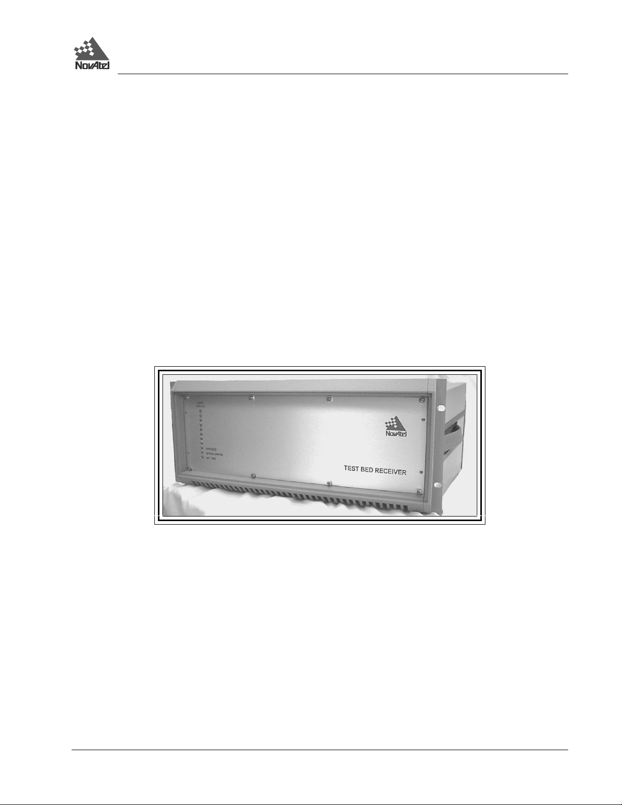
Figure 1 The NovAtel Test Bed Receiver
The Test Bed Receiver consists of two NovAtel Millennium receivers packaged along with associated support circuitry in
a NovAtel WAAS Receiver style enclosure (a 4U high 19” sub rack). The first Millennium receiver (GPS GEO) tracks
12 GPS L1/L2 satellites with narrow correlator spacing, or 10 GPS L1/L2 satellites with narrow correlator spacing and 1
WAAS satellite with wide correlator spacing or 8 GPS L1/L2 satellites with narrow correlator spacing and 2 WAAS
satellites with wide correlator spacing. The second Millennium receiver (GPS GLONASS) tracks 12 GPS L1 satellites
with narrow correlator spacing and 6 GLONASS L1 satellites with narrow correlator spacing. Refer to Default Channel
Assignments in Appendix E, Page 50 for more details on the channel configurations. Data output rates will be nominally
at one hertz.
It is possible to upgrade this configuration in the future to become a full EGNOS RIMS-C, WAAS or MSAS receiver, by
the addition of several MEDLL receiver cards and replacement of the GPS GLONASS card with a second GPS GEO
card.
The GPS GLONASS card uses Narrow Correlator tracking technology to track the L1 GPS satellite signals. This
enhances the accuracy of the pseudorange measurements as well as mitigating the effects of multipath.
The GPS GEO card will tra ck GEO satellite s that transmit using the RT CA/DO-229A WAAS signal structure . The GEO
satellites are tracked using standard correlator spacing. This configuration is chosen based on the signal bandwidth of the
IMMARSAT GEO satellites, which is constrained to 2.2 MHz. The GPS GEO card can track two C/A code GEOs on L1.
The Test Bed Receiver incorporates a L1/L2 GPSCards, which uses NovAtel’s P-Code Delayed Correlati on Technol ogy,
providing superior performance even in the presence of P-code encryption. Each GPSCard is an independent GPS
receiver.
The Test Bed Receiver is packaged in a standard 4U x 19” sub-rack. The rear panel’s 9-pin D connectors as we ll as the
antenna and external oscillator connectors provide easy I/O access.
8 Test Bed Receiver Subsystem Addendum – Rev 1
Page 9
1 - Introduction
L1/L2-II
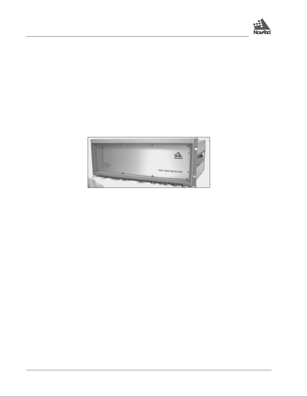
OPERATIONAL OVERVIEW
The NovAtel Test Bed Receiver has two functional blocks (see Figure 2):
• Single Frequency GPS GLONASS
• Dua l Frequency GPS GEO
Figure 2 Test Bed Receiver Functional Block Diagram
Serial Ports Strobe Port
BACKPLANE: Communication and Time Synchronization
CLK/STATUS
GEO Processing
CARD
10 MHz
OCXO
10 MHz
Int. Osc.
Output
External
Jumper
L1/L2 G PS
GLONASS
L1/L2-I
RF/IF
Digitizing
10 MHz
Ext. Osc.
Input
L1/L2 GPS
L1 GEO
RF/IF
Digitizing
RF/IF
Digitizing
Antenna
Input
5 VDC
+/- 12 VDC
POWER
SUPPLY
22-30 VDC
Power
Specific channels on the GPS GEO card have the capability to receive and process the GEO WAAS signal. The signal is
in-band at L1 and is ident ified with WAAS- specific PRN num bers. The WAAS m essage is decoded a nd separated into
its various components. The WAAS message and associated pseudorange is provided as an output.
Test Bed Receiver Subsystem Addendum – Rev 1 9
Page 10

1 - Introduction
Single Frequency GPS GLONASS
The GPS GLONASS is c onfigured to track 12 L1 C/A -code signals (Nar row Correlator tr acking technology), and 6 L1
GLONASS C/A-code signals. The output is used to compute ionospheric corr ections.
Dual Frequency GPS GEO
Within the GPS GEO group, up to 2 channels can be confi gured to track L1 C/A code GEOs
The L1 C/A code and L2 C/A code measurements are used to derive ionospheric corrections.
Other Outputs & Inputs
• A 10 MHz output is availabl e for use with an inte rnal clock.
• Tw o serial ports provide: - raw satellite measure ments (pseudorange, carr ier & time)
- receiver status data (communications & tracking)
- raw satellite data (ephemeris & almanac)
- fast code corrections for signal stability monitoring
• The receiver accepts an external input from a 10MHz atomic clock or its internal OCXO for synchronization.
10 Test Bed Receiver Subsystem Addendum – Rev 1
Page 11
2 - Installation
2 INSTALLATION OF TEST BED RECEIVER
This chapter provides sufficient information to allow you to set up and prepare the T e st Bed Receiver for initial operation.
MINIMUM CONFIGURATION
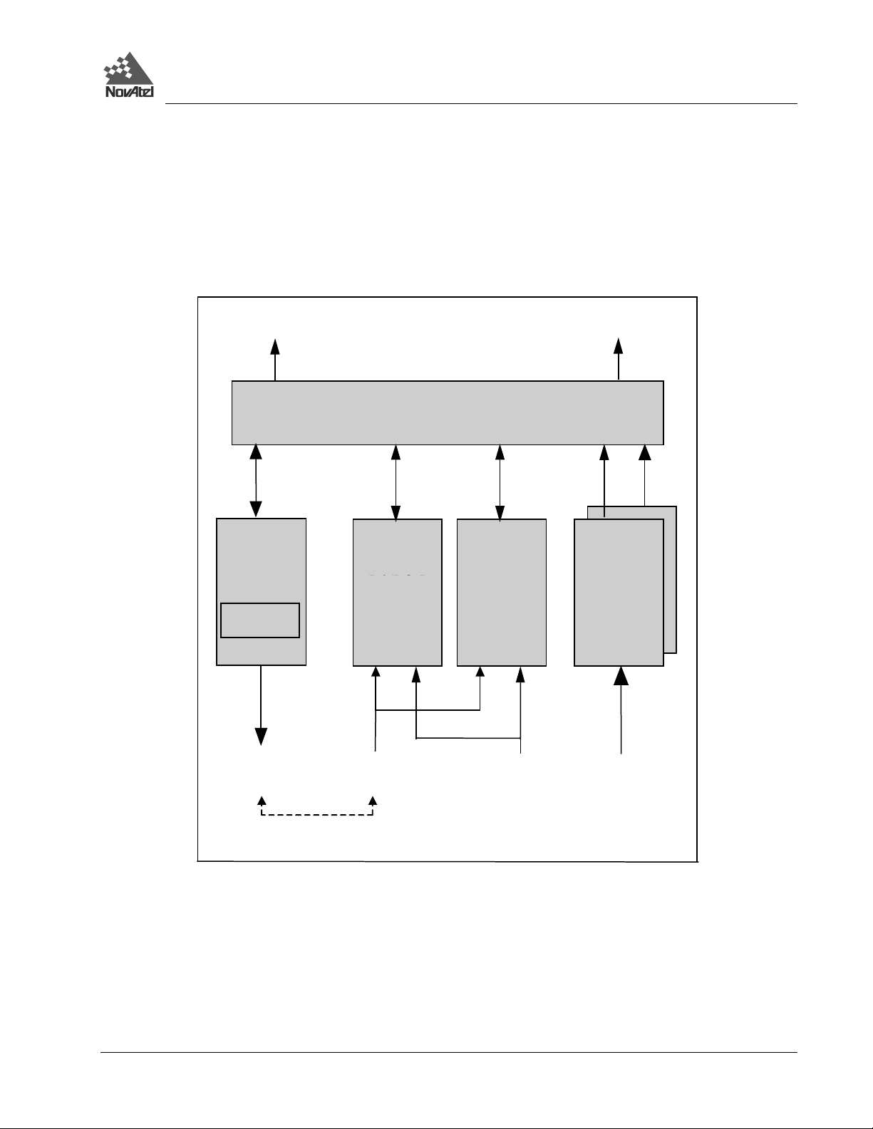
In order for the Test Bed Receiver to function as a complete system, a minimum equipment configuration is required.
This is illustrated in Figure 3.
Figure 3 Test Bed Minimum System Configuration
Antenna (L1 & L2)
GPS & GLONASS
Antenna (L1)
GPS & GEO
Power Supp ly
22 - 30 V DC
Data processing
equipment
The recommended minimum configuration and required accessories are listed below:
• NovAtel Test Bed Receiver
• User-supplied L1/L2 GPS and L1 GLONASS antennas and LN A
• Us er-supplied power suppl y (+22 to +30 V DC, 5 A maximum)
• Opt ional (could use inter nal 10 MHz OCXO) user-supplied external frequency reference (10 MH z).
• User-supplied interface, such as a PC or other data communications equipment, capable of standard serial
communications (RS-232C).
• User-supplied data and RF c ables
Of course, your intended set-up may differ significantly from this minim um configuration. The Test Bed Receiver has
many features that would not be used in the minimum confi guration shown above. This section merely describes the
basic system configuration, which you can m odi fy to meet your specific situation.
Test Bed Receiver Subsystem Addendum – Rev 1 11
Page 12
2 - Installation
For the minimum configuration, setting up the Test Bed Receiver involves the following steps:
1. Connect the user interface to the Test Bed Receiver (“GPS GLONASS” and/or “GPS GEO” connectors)
2. Install the GPS and GLONASS antennas and low-noise amplifier, and make the appropriate connections to the
Test Bed Receiver (“GPS GLONASS ANT” or “GPS GEO ANT” connector)
3. Supply power to the Test Bed Receiver (“22-30 VDC” connector)
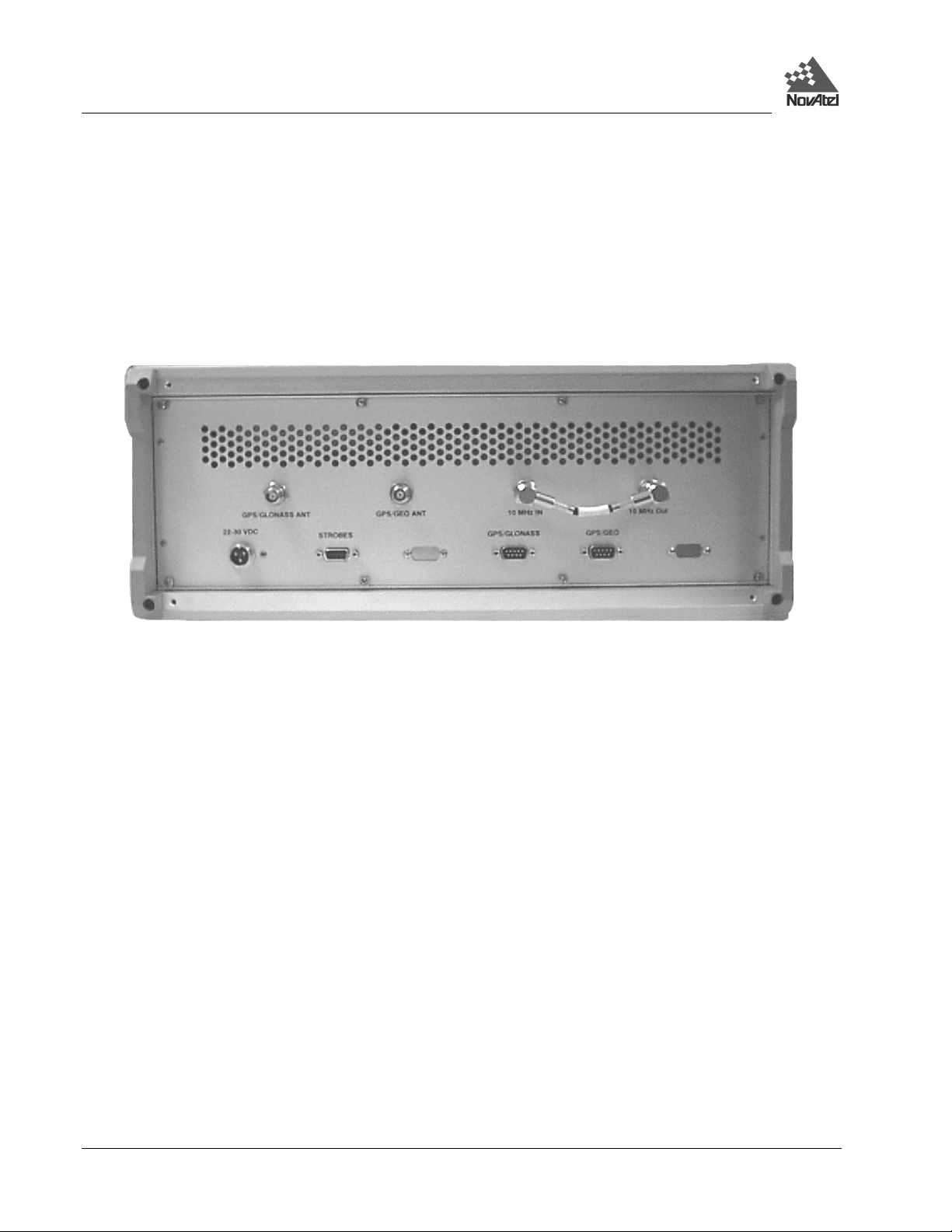
The connections on the rear panel are shown in Figure 4 below:
Figure 4 Rear Panel of Test Bed Receiver
The information from each receiver subsection is accessed through individual RS –232 serial communi cation ports. The
two ports using DE9P connectors are located on the back panel of the receiver . Serial baud rates up to 115,200 bps are
usable selectable with 9600 bps set as the default configuration. The second serial port of each receiver subsection is used
internally and is therefore not available for user access.
The receivers communicate with each other across the backplane within the enclosure. The GPS GEO receiver is
considered the master as far as the time goes. The 1PPS output of the GPS GEO receiver is connected to the Mark In
input of the GPS GLONASS receiver. The time information associated with the 1PPS pulse is sent from the GPS GE O to
the GPS GLONASS across a high-speed (TLink) serial communication line on the backplane. The GPS GLONASS then
synchronizes its time to that of the GPS GEO.
INTERNAL AND EXTERNAL OSCILLATORS
A 10 MHz OCXO is provided within the enclosure. The internal OCXO is connected to a BNC connector on the back
panel of the receiver. Another BNC connector on the back panel routes the 10 MHz external oscillator signal through a
splitter to the two receiver subsections. If the receiver is to be operated from the internal 10 MHz OCXO then a jumper
cable is connected from the 10 MHz output BNC connector to the 10 MHz input BNC connector. I f the receiver is to be
operated from an external 10 MHz frequency source such as a Cesium or Rubidium oscillator then that frequency
reference will be connected to the 10 MHz IN port on the rear panel of the receiver. In that case the 10 MHz OUT port
should be terminated with a 50
Without an external oscillator the GPS GLONASS and GPS GEO will operate independently using their own on-board
TCXO after they are give n the appropriate software command. If a n external oscillator input is not supplied, the GPS
GLONASS card must be sent the comm and “SETTIMESYNC DISABLE”. The CLOCKADJUST command should also
be enabled so that both receivers will independently try to align their time to GPS time. If the CLOCKADJUST
Ω terminator.
12 Test Bed Receiver Subsystem Addendum – Rev 1
Page 13
2 - Installation
command is disabled, or if the EXTERNAL clock command is disabled, then the two receivers will drift away from each
other in time. The normal mode of operation is to use either the internal OCXO or a highly stable external oscillator.
The 10 MHz OCXO is mounted within the enclosure on the Clock/Status card. This card has bi-colored LEDs that
visually indicate when the receiver is powered and also reflect whether the receiver has passed its power on self-test. The
lower LED will monitor the signal power of the internal 10 MHz OCXO. If it turns from green to off a failure of the
OCXO or its power supply would be indicated. Only the first, second and third LED from the bottom are used. The
others are only active when the enclosure is populated as a WAAS, MSAS, or EGNOS RIMS-C receiver.
CONNECTING THE EXTERNAL FREQUENCY REFERENCE
The Test Bed Receiver can be used with an exter nal, user-supplied frequency reference; this would typically take the
form of a high-accuracy oscillator. Please refer to Appendix B for the recommended specifications of this devic e.
The frequency reference is connected to the 10 MHz BNC female connector on the rear panel of the Test Bed Receiver.
Refer to Figure 5 below.
Figure 5 10 MHz In (External Frequency Reference) - Test Bed
th
The 11
(bottom) LED on t he front pa nel indica tes the sta tus of the inte rnal cl ock refe rence. A clear LED indicates that
no internal reference is present. Green indicates that the clock is present. Refer to Figure 6 below.
Figure 6 Lights on Front Panel of Test Bed Receiver
Test Bed Receiver Subsystem Addendum – Rev 1 13
Page 14
2 - Installation
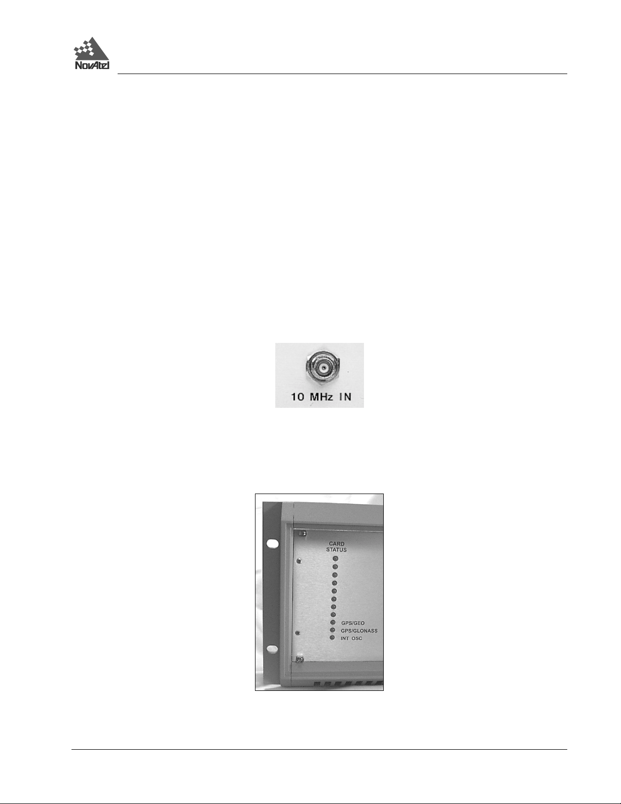
CONNECTING DATA COMMUNICATIONS EQUIPMENT
There are two serial ports on the back panel of the Test Bed Receiver; both are configured for RS-232 pr otocol. These
ports make it possibl e f or ext er nal data com m unica ti ons e quipm ent - suc h as a per sona l com pute r - t o com muni ca te wit h
the Test Bed Receiver. Each of these ports has a DE9P connector.
The GPS GLONASS and GPS GEO ports (see Figure 7) allow two-way c ommunica tions. Eac h is configur ed as COM1
if you attempt to communicate directly with it. They are each connected to a GPSCard within the Test Bed Receiver unit.
Each of these ports can be addressed inde pendently of the other.
Figure 7 Pinout for GPS GLONASS and GPS GEO Ports - Test Bed
DCD RXD TXD DTR GND
DSR RTS CTS NC
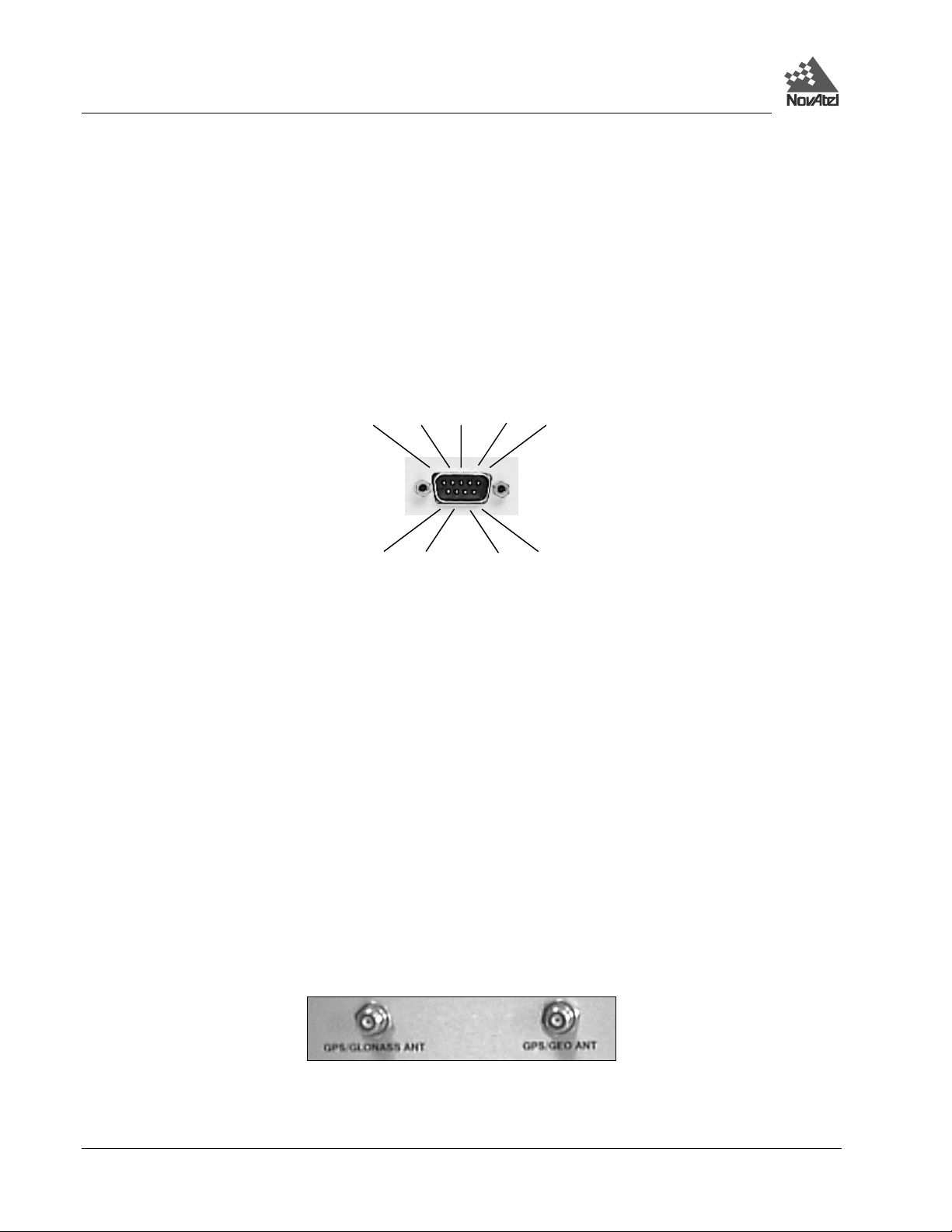
CONNECTING THE GPS ANTENNA
Selecting and installing an appropriate antenna system is crucial to the proper operation of the Test Bed Receiver.
The antenna connectors for both GPS and GLONASS are located on the back panel of the enclosure and are type TNC.
Antenna power is provi ded to the cente r pin of these c onnector s. T he power is 5 V DC with a c urre nt up to 100 m A. The
power supply for the antenna originates from each r eceiver card in this enclosur e and its status is re flected in the Antenna
Status bit of either receiver subsystem.
Keep these points in mind when installing the antenna system:
• Ideally, select an antenna location with a clear view of the sky to the horizon so that each satellite above the horizon
can be tracked without obstruction.
• E nsure that the antenna is mounted on a secure, stable structure ca pable of withstanding re levant environmenta l
loading forces ( e.g. due to wind or ice).
Use high-quality coaxial cables to minimize signal attenuation. The gain of the LNA must be sufficient to compensate for
the cabling loss.
The antenna ports on the Test Bed Receiver have TNC female connectors, as shown in Figure 8.
Figure 8 Antenna Inputs - Test Bed
14 Test Bed Receiver Subsystem Addendum – Rev 1
Page 15
2 - Installation
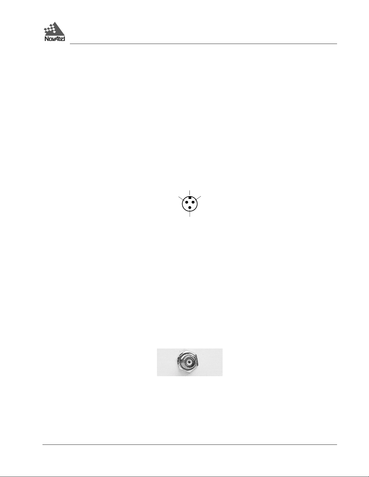
CONNECTING THE EXTERNAL POWER INPUT
The Test Bed Receiver requires one source of external regulated power . The input can be in the +22 to +30 V DC range.
The receiver draws up to 3 A at start-up, but the steady-state requirement is approximately 1.5 A.
Five and twelve volt powe r supplies are insta lled internally w ithin the enclosure. The 5-volt supply is used to power the
two receivers and the antenna. The 12-volt supply is used for OCXO power. Both of these supplies receive their power
from a connector on the enclosure back panel and accept DC power within a voltage range of +22 to +30 volts.
The power-input connector on the Test Bed Receiver is a 3-position chassis jack. It mates to a 3-position inline plug
supplied with the Test Bed Receiver. Pin 1 (+22 to +30 V DC), and Pin 2 (GND) connect to the Test Bed Receiver’s
internal power supply, which performs filtering and voltage regulation functions. Pin 3 serves as ground connection
protection. Refer to Figure 9.
Figure 9 External Power Connections - Test Bed
Notch
Pin 2
Pin 3
Pin 1
USING THE 10 MHz OUTPUT SIGNAL
The 10 MHz output provides a high-stability reference clock to the Test Bed Receiver. It permits the synchronization of
the two receiver subsystems in the Test Bed Receiver. See Internal and External Oscillators on Page 12 for more
information.
If the receiver is to be operated from the internal 10 MHz OCXO then a jumper cable is connected from the 10 MHz
output BNC connector to the 10 MHz input BNC connector (see Fi gure 10). If the receiver is to be operated from an
external 10 MHz frequency source such as a Cesium or Rubidium oscillator then that frequency reference will be
connected to the 10 MHz IN port on the rear panel of the receiver. In that case the 10 MHz OUT port should be
terminated with a 50
Ω terminator.
Figure 10 10 MHz Output – Test Bed
Test Bed Receiver Subsystem Addendum – Rev 1 15
Page 16
2 - Installation
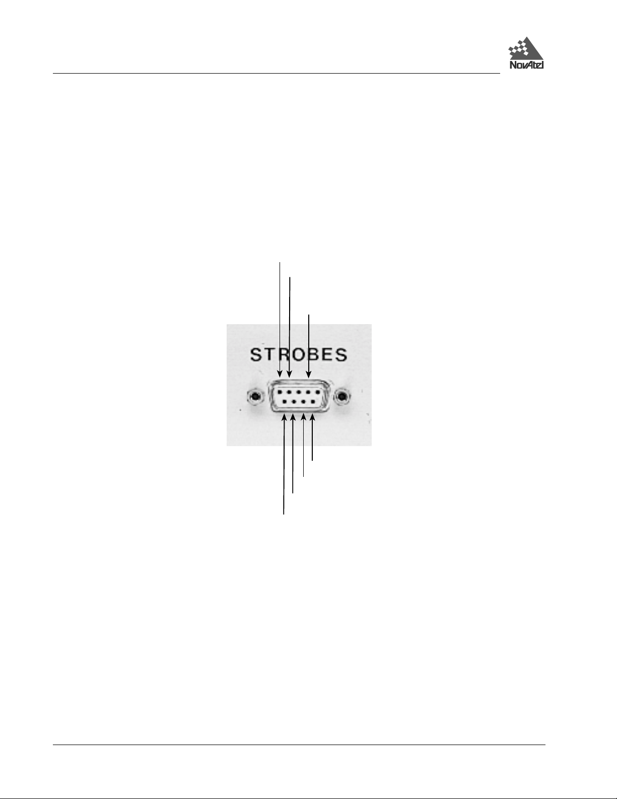
ACCESSING THE STROBE SIGNALS
A strobe port is located on the enclosure back panel. This is a diagnostic connector and is in the form of a DE9S
connector (see Figure 11). The 1PPS and Measurement pulse from both receiver subsystems are available on this
connector for verifying synchronization using an oscilloscope. These are the only strobe signals made available from the
two receiver subsystems. The specifications and electrical characteristics of these signals are described in Appendix B.
The GPS GLONASS and GPS GEO ports are each connected to a GPS receiver within the Test Bed Receiver unit.
Figure 11 Strobe 9-pin D-Connector Pinout - Test Bed
MSR GPS/GLONASS
MSR GPS/GEO
1 PPS GPS/GLONASS
GND
GND
GND
1 PPS GPS/GEO
16 Test Bed Receiver Subsystem Addendum – Rev 1
Page 17

3 - Operation
3 OPERATION
Before operating the Te st Bed Receiver for the first time, ensure that you have followed the installation instr uctions in
Chapter 2.
From here on, it will be assumed that testing and operation of the Test Bed Receiver will be performed while using a
personal computer (PC); this will allow the greatest ease and versatility.
PRE-START CHECK LIST
Before turning on power to the Test Bed Receiver, ensure that all of the following conditions have been met:
• T he antenna(s) is (are) properly inst alled and connected.
• T he PC is pr operly conne cted using a null-m odem cabl e, and its com munications pr otocol has been set up to match
that of the Test Bed Receiver.
• T he optional external frequency reference is properly installed, connecte d, powered-up, and stabilized.
Supply power to the Test Bed Receiver only after all of the above checks have been made. Note that the warm-up
process may take se veral minutes, de pending on ambient tempe rature.
SERIAL PORTS - DEFAULT SETTINGS
Because the Test Bed Receiver communicates with the user’s PC via serial ports, both units require the same port
settings. The communications settings of the PC should match these on the receiver:
• RS- 232 protocol
• 9600 bit s per second (bps)
• No parity
• 8 data bits
• 1 stop bi t
• No handshaking
• E cho off
Once initial communications are established, the port settings for the Test Bed Receiver can be changed using the COMn
command, which i s described in the MiLLennium Command Descriptions Manual.
START-UP
The Test Bed Receiver’s firmware resides in non-volatile memory. Supply power to the unit, wa it a few moments for
self-boot, and the Test Bed Receiver will be ready for comm and input.
There are two initial start-up indicators to let you know that the Test Bed Receiver’s serial ports are ready to
communicate:
1. Status lights on the Test Bed Receiver’s front panel (lower thre e L ED s) should turn from red to green to indicate that
all cards are healthy. If any one of the LEDs does not tur n green, then t he system should be considere d unreliable. If
this situation occurs, contact NovAtel Customer Service for assistance.
2. Your external terminal screen will display one of the following prompts:
Com1> if you are connected to the GPS GLONASS or GPS GEO serial port.
The Test Bed Receiver is now ready for command input from either of the two COM1 ports.
Test Bed Receiver Subsystem Addendum – Rev 1 17
Page 18

3 - Operation
INITIAL COMMUNICATIONS WITH THE TEST BED RECEI VER
Communicating with the Test Bed Receiver is a straightforward process and is accomplished by issuing desired
commands to the COM1 ports from an external serial communications device. For your initial testing and
communications, you will probably be using either a remote te rmina l or a per sonal compute r that is dir ectly connec ted to
a Test Bed Receiver’s serial port by means of a null modem cable.
To change the defa ult comm unicati on settings, such as bit rate , use the COMn command, see the MiLLennium Command
Descriptions Manual.
When the Test Bed Receiver is first powered up, no activity information is transmitted from the COMn ports except for
the COM1> prompt described in the Start-Up section above.
Commands are directly input to Test Bed Receiver using the exter nal terminal. It should be noted that most commands
do not echo a re sponse to a com m and i nput. Retur n of the COM1> prompt indic at es t hat t he c omm a nd has a ctua ll y bee n
accepted from the Test Bed Receiver. Note that VERSION is the only command that does provide an echo response other
than the port prompt .
Examples:
1. If you type VERSION <Enter> from a ter minal, this will cause the Test Bed Receiver to echo the firmwar e version
information.
2. An example of a no-echo response to an input command is the FIX POSIT ION command. It can be input as follows:
COM1>fix position 51.113 - 114.043 1060 <Enter>
This example illustrates command input to the COM1 port that sets the Test Bed Receiver’s position. However, your
only confirmation that the command was actually accepted is the return of the COM1> prompt.
If a command is erroneously input, the Test Bed Receiver will respond with the “Invalid Comma nd Option” response
followed by the COM1> prompt.
18 Test Bed Receiver Subsystem Addendum – Rev 1
Page 19

4 - Update or Upgrade
4 UPDATE OR UPGRADE YOUR GPSCARD
The MiLLennium stores its progra m firmwar e in non-volatile mem ory, which allows you to perform firmware upgrades
and updates without having to return the MiLLennium to the distributor. New firmware can be transferred to the
MiLLennium through a serial port, and the unit will immedia t ely be ready for operation at a higher level of performance.
The first step in upgrading your receiver is to contact your local NovAtel dealer. Your dealer will assist you in selecting
the best upgrade option that suits your specif ic GPS ne eds. If your needs are still unresolved after seeing your deale r then
you can contact NovAte l direc tly through any of the met hods describe d in the Software Support section, a t the beginning
of the MiLLennium Command Descriptions Manual.
When you call, be sure t o have available your MiL Lennium model number , serial number, a nd program revision level.
This informati on is printed on the ori ginal shipping box as well a s on the back side of the MiLLennium itself. You can
also verify the inf ormation by issuing the VERSION command at the port prompt.
After establishing which new model/revision level would best suit your needs, and having described the terms and
conditions, you will be issued with an authorization code (auth-code). The auth-code is required to unlock the new
features according to your authorized upgrade/update model type.
There are two procedures to choose from, depending on the type of upgrade/update you require:
1. If you are upgrading to a higher performance model at the sam e firmware revision level ( e.g. upgrading from a
MiLLennium Standard rev. 4.50, to a MiLLennium RT-2 rev. 4.50), you can use the $AUTH special command.
2. If you are updating to a higher firmwar e revision level of the sa me model (e.g. updat ing a MiLLennium Standar d
rev. 4.45 to a higher revision level of the same model, such a s MiLLennium Standard rev. 4.50), you will need to
transfer new pr ogram firmware to the M iLLennium using the Loader utility program. As the Loader and update
programs are generally provided in a com pressed f ile forma t, you will also be given a file decompr ession password.
The Loader a nd update files c an be found on NovAte l’s FTP site at http:\\www.novatel.ca, or can be sent to you on
floppy disk or by e-mail.
Your local NovAtel dealer will provide you with all the information that you require to update or upgrade your receiver.
UPGRADING USING THE $AUTH COMMAND
The $AUTH command is a special input command which authorizes the enabling or unlocking of the various model
features. Use this command when upgr ading to a higher performance MiLLennium model a vailable within the same
revision level as your current model (e.g., upgr ading from a MiLLennium Standard rev. 4.50, to a MiLLennium RT-2
rev. 4.50). This command will only function in conjunction with a valid auth-code assigned by GPS Customer Service.
The upgrade can be pe rformed directly fr om Loader’s built-in terminal emulator, GPSolution’s Comm and Line Screen,
or from any other communications program. The proc edure is as follows:
1) Power-up the MiLLennium and establish communications over a se rial port (see Chapt er 3, Operation on Page 17).
2) Issue the VERSION command to verify the c urrent firmware model number , revision level, and serial number.
3) Issue the $AUTH command, followed by the a uth-code and model type. The syntax is as follows:
Syntax:
$auth auth-code
Test Bed Receiver Subsystem Addendum – Rev 1 19
Page 20

4 - Update or Upgrade
where
$auth is a special com mand which allows program model upgrades
auth-code is the upgrade authori zation code, expr essed as hhhh,hhhh,hhhh,hhhh,hhhh,model# where the
h characters are an ASCII hexadecimal code, and the model# would be ASCII text
Example:
$auth 17cb,29af,3d74,01ec,fd34,millenrt2
Once the $AUTH command has been exec uted, the MiLLennium will reboot itself. Issuing the VE RSION command
will confirm the new upgrade model type and version number.
UPDATING USING THE LOADER UTILITY
Loader is required ( instead of the $A UTH comm and) when updati ng previously rel eased fir mware wi th a newer ver sion
of program and model firmw are (e .g., updat ing a MiLL ennium Standa rd rev. 4.45 to a higher revi sion level of the same
model, such as MiL Lennium Standard rev. 4.50) . Loader is a DOS utility program designed to facilitate program and
model updates. Once Loader is installed and running, it will allow you to sele ct a host PC serial port, bit rate, director y
path, and file name of the new program firmware to be transferred to the MiLLennium.
TRANSFERRING FIRMWARE FILES
To proceed with your program update, you must first acquire the latest firmware revision. You will need a file with a
name such as OEMXYZ.EXE (where XYZ is the firm ware revision level). This file is available from NovAtel’s FTP
site (http:\\www.novatel.ca
you on floppy disk. For more i nformation on how to contact NovAt el Customer Se rvice please see the Sof tware Support
section at the beginning of the MiLLe nnium Command Descriptions Manual.
You will need at least 1 MB of available space on your hard drive. For convenience, you may wish to copy this file to a
GPS sub-directory (e.g., C:\GPS\LOADER).
The file is available in a compressed format with password protection; Customer Service will provide you with the
required password. After copyi ng the file to your computer, i t must be decom pressed. The synt ax for decompression is
as follows:
Syntax:
[filename] -s[password]
where
filename is the name of the compressed file (but not including the .EXE extension)
-s is the password command switch
password is the password requi red to allow decompression
Example:
oem442 -s12345678
The self-extracting archive will then generate the following files:
), or via e-m ail (support@novat el.ca). If tr ansferr ing is not possible, the file can be ma iled to
• LOADER.EXE Loader utility program
• LOADER.TXT Instructions on how to use the Loader utility
• XYZ.BIN Firmware version update file, where XYZ = pr ogram version level (e.g. 442.BIN)
20 Test Bed Receiver Subsystem Addendum – Rev 1
Page 21

4 - Update or Upgrade
USING THE LOADER UTILITY
The Loader utility can operate from a ny DOS directory or drive on your PC. The program is compri sed of three parts:
Program Card (authoriza tion procedure) , Setup (comm unications configur ation) and Terminal (terminal emulator). The
main screen is shown in Figure 12.
Figure 12 Main Screen of LOADE R Program
If you are running Loader for the first time, be sure to access the Setup menu (step 3 below) before proceeding to
Program Card (step 4 below) ; otherwise, you can skip st ep 3. The procedure i s as follows:
1. Turn off power to the MiLLennium .
2. Start the Loader program.
3. From the main menu screen, select Setup to configure the serial port over which communication will occur
(default: COM1) , and the data transf er rates for both pr ogramming (default: 115 200 bits pe r second) and termina l
emulation (default: 9600 bps). To m inimize the time r equired, select the highest serial bit rate your PC can reliably
support. Loader will verify and save your selections in a file name d LOADER.SET, and return to the main menu
screen.
4. From the main screen, select Program Card.
5. Sel ect the disk dr ive ( e. g., A, B, C, D) in whi ch the updat e f ile (e .g. 442.BIN) is located. Select the path where the
update program file is loc ated
(e.g., C:\GPS\LOADER); the directory from w hich you sta rted Loader is the default
path. Select the required update file (e.g. 442.BIN).
6. At the prompt, e nter your update auth-code (e.g. 17b2,32df,6ba0,92b5,e5b9,millenrt2).
7. When prompted by the program, turn on power to the MiLLennium. Loader will automatically establish
communications with the MiLLennium. The time required to transfer the new program data will depend on the bit
rate, which was selected earlier.
8. When the transfer is complete, use a terminal emulator such as that in Loader (select Terminal) to issue the
VERSION command; this will verify your new program version number. When using the terminal emulator in
Loader, a prompt does not initially appear; you need to enter the command first, which then produces a r esponse,
after which a prompt will appear.
9. Exit Loader (select Quit).
This completes the procedure required for field- updating a MiLLennium.
Test Bed Receiver Subsystem Addendum – Rev 1 21
Page 22

Appendices
A WAAS OVERVIEW
The Wide Area Augmentation System (WAAS) is a safety-critical system which is designed to enable the GPS to meet
the US Feder al Aviation Administration (FAA) na vigation performance requirem ents for domestic en route, terminal,
non-precision approa ch and precision approach phases of flight. The primary functions of WAAS include:
• data collection
• dete rmining ionospheric corrections, satellite orbits, satellite clock corrections and satellite integrity
• independent data verification
• WAAS message broadcas t and ranging
• syste m operations & mai nt enance
Figure 13 The WAAS Concept
As shown in Figure , the WAAS is made up of a serie s of Wide Area Refere nce Stations, Wide Area Master Stations,
Ground Uplink Stations and Geostationary Satellites (GEOs). The Wide Area Reference Stations, which are
geographically distributed, pick up GPS satellite data and route it to the Wide Area Master Stations where wide area
corrections are gener ated. These corr ections a re se nt to the G round Uplink St ations, w hich up-l ink them to the GEOs for
re-transmission on the GPS L1 frequency. These GEOs transmit signals which carry accuracy and integrity messages,
and which also provide additional ranging signals for added availability, continuity and accuracy. These GEO signals are
available over a wide area and can be received and processed by ordinary GPS receivers. GPS user receivers are thus
able to receive WAAS data in-band and use not only differential corrections, but also integrity, residual errors and
ionospheric information for each monitored satellite.
The signal broadcast vi a the WAAS GEOs to the WAAS use rs is designed to minimize m odifications to standard GPS
receivers. As such, the GPS L1 frequency (1575.42 MHz) is used, together with GPS-type modulation - e.g. a
Coarse/Acquisition (C/A) pse udorandom (PRN) code. In addition, the code phase timing is maintaine d c l ose to GPS time
to provide a ranging capability.
22 Test Bed Receiver Subsystem Addendum – Rev 1
Page 23

Appendices
B GLONASS OVERVIEW
MILLENNIUM-GLONASS GPSCARD
The MiLLennium-GLONASS GPSCard can receive L1 signals from combined GPS/GLONASS satellites. This hybrid
receiver offers combined GPS/GLONASS position solutions.
An RTK version of the MiLLennium-GLONASS GPSCard performs significantly better when tracking GPS and
GLONASS satellites, than when tracking GPS satellites only. Faster floating-ambiguity solutions mean shorter
observations times.
The use of GLONASS in addition to GPS provides very significant advantages:
increased satellite signal observations
markedly increased spatial distribution of visible satellites
reducti on in the Horizontal and Vertical Dilution of Precision factor
no special precision degrading mode in GLONASS (unlike GPS Selective Availability mode)
single frequency (L1) positioning accuracy is about 4 times better for GLONASS as compared to GPS single
frequency signals
improve d RTK performance
decreased occupation times result in faster surveying
The MiLLennium-G LONASS G PSCard is c apable of combined GPS/G LONA SS operati on. In orde r to tra ck GLON ASS
satellites the MiLLennium must track at least one GPS satellite to determine the GPS/GLONASS time offset. In order to
determine a position in GPS-Only mode the receiver must track a minimum of four satellites, representing the four
unknowns of 3-D position and time. In combined GPS/GLONASS mode the receiver must track five satellites,
representing the same four previous unknowns as well as the GPS/GLONASS time of fset.
With the availability of combined GPS/GLONASS receivers, users have access to a potential 48-satellite combined
system. With 48 sate llites, performance in urban canyons and other locations with re stricted visibility, such as forested
areas, is impr oved, as more satellites ar e visible in the non-blocked portions of the sky. A larger sate llite constellation
also improves real-time carrier-phase differential positioning performance. In addition, stand-alone position accuracies
improve with the combined system, and in the absence of deliberate accuracy degradation, differential GLONASS
requires a much l ower correcti on update rate.
Table 1 lists the two types of NovAtel MiLLennium-GLONASS GPSCards available, each capable of multiple
positioning modes of operation:
Table 1 Positioning Modes of Operation
Positioning Modes of Operation MiLLennium-GLONASS GPSCard
MiLLen-G MiLLen-G-RT10 TESTBEDGLO
Single Point
Waypoint Navigation
Pseudorange differential corrections (TX & RX)
√ √ √
√ √ √
√ √ √
RTK pseudorange & carrier-phase double differencing:
< 10 cm RMS accuracies (floating)
Test Bed Receiver Subsystem Addendum – Rev 1 23
X
√
X
Page 24

Appendices
The NovAtel MiLLennium-GLONASS GPSCards can be applied in mining and machine control, robotics, flight
inspection, marine navigation, agriculture, military, direction finding and other custom OEM applications.
Some of the information used to create the Introduction was obtained from two sources.
1. Langley, Richard B. “GLONASS: Review and Update”. GPS World
2. Kleusberg, Alfred. “Comparing GPS and GLONASS”. GPS World
, July 1997. 46-51
, December 1990. 52-54
GLONASS SYSTEM DESIGN
As with GPS, the GLONASS system uses a satellite constellation to ideally provide a GLONASS receiver with six to
twelve satellites at most times. A minimum of four satellites in view allows a GLONASS receiver to compute its
position in three dimensions, as well as become synchronized to the system time.
The GLONASS system de si gn consists of three parts:
• The Space segment
• The Control segment
• The User segment
All these parts operate together to provide accurate three-dimensional positioning, timing and velocity data to users
worldwide.
The Space Segment
The Space Segment is the portion of the GLONASS system that is located in space, that is, the GLONASS satellites and
any ancillary spacecraft that provide GLONASS augmentation information (i.e., differential corrections, integrity
messages, etc.). This segment is composed of the GLONASS satellites which, when complete, will consist of 24
satellites in three orbital planes, with eight satellites per plane, see Figure 14, Page 25. Foll owing are points about the
GLONASS space segment.
• The orbit period o f each satellite is approximately 8/17 of a sidereal day such that, after eight
sidereal days, the GLONASS satellites have completed exactly 17 orbital revolutions. A sidereal
day is the rotation period of the earth and is equal to one calendar day minus four minutes.
• Because each orbital plane contains eight equally spaced satellites, one of the satellites will be at the
same spot in the sky at the same sidereal time each day.
• The satellites are placed into nominally circular orbits with target inclinations of 64.8 degrees and
an orbital height of about 19,123 km, which is about 1,060 km lower than GPS satellites.
• The GLONASS satellite signal identifies the satellite and provides:
the positioning, velocity and acceleration vectors at a reference epoch for computing satellite locations
o
o synchronization bits
o data age
o satellite health
o offset of GLONASS time
o almanacs of all other GLONASS satellites.
• The GLONASS satellites each transmit on different L1 and L2 frequencies, with the P code on both
L1 and L2, and with the C/A code, at present, only on L1. L1 is currently centered at 1602 - 1615.5
MHz.
• Some of the GLONASS transmissions initially caused interference to radio astronomers and mobile
communication service providers. The Russians consequently agreed to reduce the number of
24 Test Bed Receiver Subsystem Addendum – Rev 1
Page 25

Appendices
frequencies used by the satellites and to gradually change the L1 frequencies to 1598.0625 -
1609.3125 MHz. Eventually the system will only use 12 primary frequency channels (plus two
additional channels for testing purposes).
• System operation (24 satellites and only 12 channels) can be accomplished by having antipodal
satellites, satellites in the same orbit plane separated by 180 degrees in argument of latitude,
transmit on the same frequency. This is possible because the paired satellites will never appear at the
same time in your view. Already, eight pairs of satellites share frequencies.
Unlike GPS satellites, all GLONASS satellites transmit the same codes. They derive signal timing and frequencies from
one of three onboar d ce sium atom ic c locks opera ting a t 5 MHz . The si gnals ar e ri ght-hand c ircul arly pol ariz ed, li ke GPS
signals, and have comparable signal strengt h.
Figure 14 View of GLONASS Satellite Orbit Arrangement
The Control Segment
The Control Segment consi sts of the system control cente r and a network of command tracking stations acr oss Russia.
The GLONASS control segment, similar to GPS, must monitor the status of satellites, determine the ephemerides and
satellite clock offsets with respect to GLONASS time and UTC (SU) tim e, and twice a day upload the navigation data to
the satellites.
The User Segment
The User Segment consists of equipment (such as a NovAtel MiLLennium-GLONASS GPSCard receiver) which tracks
and receives the satellite signals. This equipment must be capable of simultaneously processing the signals from a
minimum of four satellites to obtain accurate position, velocity and timing measurements. Like GPS, GLONASS is a dual
military/civilian-use system. Selective availability, however, will not be implemented on GLONASS C/A code. The
system’s potential civil applications are many and mirror that of GPS.
Test Bed Receiver Subsystem Addendum – Rev 1 25
Page 26

Appendices
TIME
The GLONASS satellites broadcast their time within their satellite messages. NovAtel’s MiLLennium GLONASS
GPSCard is able to receive and record both time references as well as report the offset information between GPS and
GLONASS time (see the GCLA/B log on Page 41). Although similar, GPS and GL ONASS have several differences in
the way they report time. Please see the following sections for information of GLONASS time.
GLONASS TIME VS. LOCAL RECEIVER TIME
GLONASS time is based on an atomic time scale similar to GPS. This time scale is Universal Time Coordinated as
maintained by the former Soviet Union (UTC (SU)).
Unlike GPS, the GLONA SS time scale is not conti nuous and must be adjusted for per iodic leap seconds. Leap seconds
are applied to all UTC time references about every other year as speci fied by the International Earth Rotation Servic e
(IERS). Leap seconds are necessary because the orbit of the earth is not unifor m and not as accurate as the atomic time
references.
GLONASS time is maintained within 1 ms of UTC (SU) by the control segment with the remaining portion of the offset
broadcast in t he navigation me ssage. As well, t he GLONASS time is of fset from UTC ( SU) by plus three hours due to
control segment specific issues. The GCLA/B log (see Page 41) contains the offset information between GPS and
GLONASS time.
DATUM
Because a consistent transforma tion between WGS84 and the Parametry Zemli 1990 (PZ 90) or, in English translation,
Parameters of the Earth 1990 geodetic datum has not been defined, we have allowed for a new command,
PZ90TOWGS84, and a new parameter, PZ90, for the DATUM command.
The PZ90TOWGS84 command (see Page 35) is intended to define the PZ90 transform for transferring GLONASS
satellite coordinates to WGS84. However, it can also be used, in conjunction with the DATUM PZ90 command (see the
DATUM command in the MiLLennium Command Desc riptions Manual), to allow for posi tion output in a user-defined
PZ90 frame. The PZ90TOWGS84 command will override the default values for the DATUM PZ90 command and set
them to the user-defined values. If the PZ90TOWGS84 command is not issued, the DATUM PZ90 command will use the
default PZ90 values (see the PZ90TOWGS84 command on Page 35) for the output position parameters. The PZ90
transform par ameters can be saved in user-configurable memory for immediate use on power up.
26 Test Bed Receiver Subsystem Addendum – Rev 1
Page 27

Appendices
FUNCTIONAL OVERVIEW
MILLENNIUM-GLONASS GPSCARD SYSTEM
The MiLLennium-GLONASS GPSCard consists of a radio frequency (RF) and a digital electronics section. Prior to
operation, a GPS/GLONASS antenna, power supply, and data and signal interfaces must be connected. The overall
system is represented in Figure 15. A brief description of each section follows.
Figure 15 MiLLennium-GLONASS GPSCard System Functional Diagram
1
3
21
13
6
16 17
19
7
8
9
10
11
12
23
18
4
2
22
14 15
20
19
5
Reference Description Reference Description
1 MiLLennium-GLONASS GPSCard 11 Input timing strobe
2 RF section 12 Output timing strobe
3 Digital section 13 VCTCXO
4 Antenna capable of receiving L1 signal 14 RF - IF sections, NovAtel
GPS/GLONASS antenna or user-supplied 15 Signal Processor
5 Optional user-supplied LNA power 16 32-bit CPU
(0 - 30 VDC) 17 System I/O
6 User-supplied power (5 VDC) 18 LNA
7 Optional external oscillator (5 or 10 MHz) 19 Clock signals
8 User-supplied data and signal processing 20 AGC signals
equipment 21 Control signals
9 COM1 22 RF and power connectors
10 COM2 23 Primary antenna feed
Test Bed Receiver Subsystem Addendum – Rev 1 27
Page 28

Appendices
GPS/GLONASS ANTENNA
The purpose of the GPS/GLONASS antenna is to convert the electromagnetic waves transmitted by the combined
GPS/GLONASS satellites at the L1 frequency (1575.42 MHz for GPS and 1602 - 1615.5 M Hz for GLONASS) into RF
signals. The MiLLennium-GLONASS GPSCard will function best with an active GPS/GLONASS antenna; there is a
hardware provision to select an internal or external DC power supply for an active GPS/GLONASS antenna. Note that
the antenna self-test will return a “fail” condition if a passive antenna i s used (for furthe r information on se lf-test stat us
codes, please see the RVSA/B log in the MiLLennium Command Descriptions Manual. NovAtel active antennas are
recommended.
NovAtel offers the 504 and 514 model antennas to work with your MiLLennium-GLONASS GPSCard system. Both
antennas use low-profile microstrip technology and include band-pass filtering and an LNA. The GPS/GLONASS
antenna you choose will depend on your particular application. The NovAtel antennas available to work with your
MiLLennium-GLONASS GPSCard system are single-frequency models, and each of these models offers exceptional
phase-center stability as well as a significant measure of immunity against multipath interference. Both models have an
environmentally-sealed radome.
NovAtel also offers high-quality c oaxial cable in standard 5 (Model C005), 15 (Mode l C015) and 30 m (Model C030)
lengths. These come with a TNC male connector at each end. Should your application require the use of cable longer than
30 m you will find the application note Extended Length A ntenna Cable Runs at our website, http://www.novatel.ca
you may obtain it from NovAtel Customer Service directly, see the Software Support section at the beginni ng of the
MiLLennium Command Descriptions Manual for contact information.
, or
While there may be other coaxial cables and antennas on the market that may also serve the purpose, please note that the
performance spe cifications of t he MiLLennium- GLONASS GPSCard a re warrante d only when it is used with NovAte lsupplied accessories.
RADIO FREQUENCY (RF) SECTION
The MiLLennium-GLONASS GPSCard receives partially filtered and amplified GPS and GLONASS signals from the
antenna via the coaxial cable. The RF section does the following:
• filters the RF signals to reduce noise and interference
• down-converts (with further band-limiting) the RF signals to intermediate frequencies (IFs) that are
suitable for the analog-to-digital (A/D) converter in the digital electronics section
• amplifies the signals to a level suitable for the A/D converter in the digital electronics section
• receives an automatic gain control (AGC) input from the digital signal processor (DSP) to maintain
the IF signals at a constant level
• supplie s power to the active antenna through the coaxial cable while maintaining isolation between
the DC and RF paths. A hardware jumper configuration is provided to select an internal or external
DC power supply for the active GPS/GLONASS antenna.
The RF section can reject a high level of potential interference (e.g., MSAT, Inmarsat, cellular phone, and TV subharmonic signals) .
DIGITAL ELECTRONICS SECTION
The digital section of the MiLLennium-GLONASS GPSCard receives down-converted, amplified combined GPS/
GLONASS signals which i t digitizes and processes to obtain a G PS solution (position, speed, direction and time). The
digital section consists of an analog-to-digital converter, a 32-bit 25 MHz system processor, memory, control and
configuration logi c, signal processing ci rcuitry, serial per ipheral devices, and supporting ci rcuitry. I/O data and tim ing
strobe signals are r oute d to a nd fr om the boa rd vi a a 64-pi n DI N 41612 Type B male connect or. Two EI A RS-232C seri al
28 Test Bed Receiver Subsystem Addendum – Rev 1
Page 29

Appendices
communications ports support user-selectable bit rates of 300 - 115,200 bps, with a default of 9600 bps. The digital
section does the following:
• converts the IF analog signals to a digital format
• tracks the C/A codes and carrier phases of the satellites in use
• performs channel and loop control
• performs position computation
• executes na vigation software
• performs database management
• monitors self-test system status
• controls diagnostic LEDs: a red one which only lights up to indicate an error condition, and a green
one (the “heartbeat”) which blinks on and off at approximately 1 Hz to indicate normal operation.
• controls I/O functions
You configure the MiLLennium-GLONASS GPSCard using special com mands (see Appendix D GLONASS Commands
and Logs on Page 34). In turn, the MiLLennium- GLONASS GPSCard present s information to you in the form of pre-
defined logs in a number of formats. In addition, when a MiLLennium-GLONASS GPSCard is linked to a NovAtel
GPSCard receiver or second MiLLennium-GLONASS GPSCard for differential positioning, they can communicate
directly through thei r serial ports.
Test Bed Receiver Subsystem Addendum – Rev 1 29
Page 30

Appendices
C WAAS COMMANDS AND LOGS
These comma nds and logs dif fer from the ver sions desc ribed i n the MiL Lennium Comm and Desc ripti ons Manual for the
Test Bed Receiver at the time of this publication.
COMMANDS
CONFIG
This command switches the cha nnel configuration of the GPSCard betw een pre-defi ned configurations. When invoked,
this command loads a new satellite channel-configuration and forces the GPSCard to reset. The types of configurations
possible are listed by entering this command:
HELP CONFIG
In some applications, only the standar d (defa ult) configur ation will be listed in r esponse. The standard configura tion of a
MiLLennium GPSCard consists of 12 L1/L2 channel pairs.
Syntax:
CONFIG
cfgtype
Command
CONFIG Command
cfgtype (none) Displays present channel configuration
Option Description Defa ult
WF2L1L2 for TESTBEDW
configuration
name
Loads new configuration, resets GPSCard:
TESTBEDW WF2L1L2 8 L1/L2 + 2 WAAS FEC
WF1L1L2 10 L1/L2 + 1 WAAS FEC
L1L2 12 L1/L2
MiLLen-STD STANDARD 12 GPS
WAASCORR 10 GPS + 1 WAAS
WAASCORR2 8 GPS + 2 WAAS
STANDARD for MiLLen-STD
30 Test Bed Receiver Subsystem Addendum – Rev 1
Page 31

Appendices
IONOMODEL
This command allow s the user to influe nce what ionospher ic cor rect ions the c ard uses . This c omma nd curr ently doe s not
effect the ionospheric model that is used whe n the card is operating in RT K mode. Additional range va lues are rese rved
for future use.
The MiLLenni um by default compute s ionospheric correcti ons by attempting to use L1 & L2 signals f irst. To use the
ionospheric corrections issued by the WAAS GE O satellite as a first choice, you need to issue the IONOMODE L WAAS
command.
Syntax:
IONOMODEL
Syntax
IONOMODEL
keyword
[keyword]
Range Value
WAAS
L1L2
KLOBUCHAR
AUTO
Description
Command
Card will use ionospheric corrections from WAAS broadcast
messages as a first choice
You must verify that the CONFIG command is set to either
WF1L1L2 or WF2L1L2 for this command to work, see Page 30.
Card will use ionospheric corrections derived from L1 and L2 GPS
measurements as a first choice. Card must have L2 observations
in order for this setting to be effective.
1
Card will use ionospheric corrections as calculated by the
broadcast klobuchar model parameters as a first choice.
Card will decide which ionospheric corrections to use based on
availability. (default)
Note: You cannot change GPSCard modes on the fly because once a CONFIG command is issued, the card resets itself
and starts the new m ode requested.
1
Please refer to ICD-GPS-200 for a description of the Kl obuchar model and its paramet ers. To obtain copies of ICD-GPS-200
from the ARINC Research Corporation, contact them at the address given in Appendix F of the MiLLennium Command
Descriptions Manual.
Test Bed Receiver Subsystem Addendum – Rev 1 31
Page 32

Appendices
WAASCORRECTION
This command allows you to have an affect on how the card handles WAAS corrections. The card will switch
automatically to Pseudorange Diffe rential (RTCM or RTCA) or RTK if the appr opriate corrections are being received,
regardless of the c urrent setting.
The ability to incorporate the WAAS corrections into the position solution is not the default mode. First enter the
following comma nd to put the card in WAAS mode:
config waascorr
Note: You cannot change GPSCard m odes on the fly because once a CONFIG comm and is issued the card r esets itself
and starts the newly requested mode.
To enable the position solution corrections, you must issue the WAASCORRECTION ENABLE command.
Syntax:
WAASCORRECTION
keyword
[PRN] [mode]
Syntax
WAASCORRECTION
keyword
[PRN] 120-138 - Card will use WAAS corrections from this PRN.
[mode] NONE
Range Value
ENABLE
DISABLE
WAASTESTMODE
EGNOSTESTMODE
Description
Command
- Card will use the WAAS corrections it receives.
- Card will not use the WAAS corrections that it receives.
- If no PRN is specified, the receiver will automatically select the
best PRN (with the highest elevation and with a lock time greater
than 134 seconds) to use when multiple GEOs are being tracked.
If no GEO has a lock time of more than 134 seconds, the GEO
with the highest amount of lock time is selected.
- Default. Card will interpret Type 0 messages as they are
intended (as do not use).
- Card will interperet Type 0 messages as Type 2.
- Card will ignore the usual interpretation of Type 0 messages
(as do not use) and continue.
Example:
waascorrection enable 122 waastestmode
32 Test Bed Receiver Subsystem Addendum – Rev 1
Page 33

Appendices
LOGS
RCCA RECEIVER CONFIGURATION
This log outputs a list of all current GPSCard command settings. Observing this log is a good way to monitor the
GPSCard configuration se ttings. See RCCA in the MiLLennium Command Descriptions Manual for the RCCA default
list.
The following are the default parameters, for the TESTBEDW receiver, that are different than the standard Millenium
WAAS receiver configuration:
CLOCKADJUST DISABLE
EXTERNALCLOCK OCXO
LOG CONSOLE TM1A ONTIME 10 HOLD*
* The logging of the TM1A log is done in order to time synchronize the TESTBEDGLO receiver to the
TESTBEDW receiver.
The following are the default parameters, for the TESTBEDGLO receiver, that are different than the standard Millenium
Glonass receiver configuration:
CLOCKADJUST DISABLE
EXTERNALCLOCK OCXO
SETTIMESYNC ENABLE*
* The SETTIMESYNC ENABLE allows the TESTBEDGLO receiver to accept the TM1A logs from the
TESTBEDW receiver for time synchronization.
Test Bed Receiver Subsystem Addendum – Rev 1 33
Page 34

Appendices
D GLONASS COMMANDS AND LOGS
GLONASS-SPECIFIC COMMANDS
This chapter describes MiLLennium-GLONASS GPSCard commands important to GLONASS.
GLONASS-specific commands are generated by using information obtained from the GLONASS satellite system. Please
see the following sections for definitions of t hese commands.
DGLOTIMEOUT
The differential GLONASS time out (DGLOTIMEOUT) command’s function is to set the maximum age of differential
data that will be accepted when operating as a remote station. Differential data received that is older than the specified
time will be ignored.
The ephemeris del ay of the r efe rence station is the same as for GPS and ca n be set using the DGPSTI MEO UT comm and
(refer to the MiLLennium Command Descriptions Manual for inf ormation on this command).
Since there is no Selective Availability (SA) on the GLONASS correction the degradation over time is considerably less.
It could be useful to allow a longer timeout for GLONASS than GPS.
Syntax:
Options:
DGLOTIMEOUT delay
delay: 2 - 1000 (seconds) (default 60)
34 Test Bed Receiver Subsystem Addendum – Rev 1
Page 35

Appendices
tive sign for counter clockwise direction and a negative sign for
axis [arcsec]. A positive sign for counter clockwise direction and a negative sign
PZ90TOWGS84
This command allows the user to input the Helmert transforma tion relating the GLONASS PZ90 reference fr ame to the
GPS WGS-84 reference frame. In this case, (x,y,z) is the desired WGS-84 coordinate set and (u,v,w) is the given
coordinate set i n PZ90. The tr ansf orm a tion is def ine d by an or igin of fs et (
of small angle rot ations (
those published by Misra et al. (ION GPS 96, pg 307) .
ε,φ,ω), given in radians, around the u,v and w axes respectively. By default, the values are set to
There are a numbe r of di fferent transform ations that have been published but the majority of them are optimized f or the
particular region of the planet that the data was collected in. One of the objectives of the current International Glonass
Experiment (IGE) is to accurately determine a PZ90 to WGS-84 transformation that is consistent on a global scale.
The PZ90TOWGS84 c omm a nd can be used i n conjunc tion w ith t he D AT UM PZ90 c omm and ( se e D atum on P age 26) to
allow for position output in a user-defined PZ90 frame.
The relevant parameters for the PZ90 ellipsoid are from the GLONASS Interface Control Document (ICD) version 4.0,
1998 Coordination Scientific Information Center (CSIC). Please see the following table for the reference ellipsoid
constants.
ELLIPSOID a (metres) 1/f f
∆x,∆y,∆z), a linear scale factor (δs) and a series
Parameters of Earth 1990
6378136.0 298.257839303 0.00335280374302
Syntax:
PZ90TOWGS84 option [∆x] [∆y] [∆z] [δs] [ε] [φ] [ω]
Options:
ARGUMENT DESCRIPTION
DEFAULT
SET Set to user specified values (all must be specified, see the following secti on of this table)
PARAMETER DESCRIPTION
∆x
∆y Origin offset in y direction [m]
∆z Origin offset in z direction [m]
δs Scale factor given in parts per million (ppm), final linear scale factor given as (1 + δs*10-6)
ε
φ
ω
Set to default Helmert transformation parameters
Origin offset in x direction [m]
Small angle rotation around u axis [arcsec]. A posi
clockwise direction taking into consideration that the trasformation is going from PZ90 to WGS84.
Small angle rotation around v axis [arcsec]. A positive sign for counter clockwise direction and a negative sign for
clockwise direction taking into consideration that the trasformation is going from PZ90 to WGS84.
Small angle rotation around w
for clockwise direction taking into consideration that the trasformation is going from PZ90 to WGS84.
Example:
PZ90TOWGS84 DEFAULT
PZ90TOWGS84 SET 0.1,0.4,-0.3,6,0,0,4
NOTE: T he format and sign c onventions in this comm and are set up to conf orm to the given re ference and diffe r from
the NovAtel USERDATUM command.
Test Bed Receiver Subsystem Addendum – Rev 1 35
Page 36

Appendices
UNIMPLEMENTED COMMANDS
Currently, the ability to set satellite health, and the ability to de-weight the range of a satellite in the solution
computations, is not enabled for GLONASS. Because of this, the following commands will not work with the
MiLLennium-GLONASS GPSCard for GLONASS satellites.
• SETHEALTH
• RESETHEALTH
• RESETHEALTHALL
• LOCKOUT
NOTE: The unimplemented commands are disabled for GLONASS satellites only. These commands can still be used
with GPS satellites.
If, by mistake, you issue an unimplemented command to the MiLLennium-GLONASS GPSCard for a GLONASS
satellite, the MiLLennium-GLONASS GPSCard will simply inform you that the PRN is invalid. The MiLLenniumGLONASS GPSCard is unable to accept a GLONASS PRN as an argument.
For further information on these commands, please consult t he MiLLennium Command Descriptions Manual.
GLONASS-SPECIFIC LOGS
GLONASS-specific logs provide data by using information obtained from the GLONASS satellite system. Following are
the descriptions of MiLLennium-GLONASS GPSCa rd’s CALA/B, GALA/B, GCLA/B and GEPA/B logs. The syntax
and fields are as described below.
CALA/B CALIBRATION INFORMATION
GPS satellites all broadcast on the same frequency but broadcast different codes. GLONASS satellites broadcast on
different frequencies but use the same code. The former technique is known as Code Division Multiple Access (CDMA)
while the latter is known as Frequency Division Multiple Access (FDMA).
Frequency dependent characteristic s of the hardware r esult in small biases in the GLONASS pseudoranges. You can enter
calibration numbers for the various frequencies which will be subtr acted from each pseudorange with the CALA/ B input.
The numbers can a lso be output as a log, CALA /B.
CALA
Structure:
$CALA week
bias 1
...
bias 32 std. dev. bias 32
[CR][LF] *xx
sec reserved reserved
std. dev. bias 1
36 Test Bed Receiver Subsystem Addendum – Rev 1
Page 37

Appendices
Field #
1
2 Week GPS week number 992
3 Sec GPS time into week, in seconds 453075
4 Reserved for future use
5 Reserved for future use
6,7
8, 9,
10, 11,
...,
50, 51,
52, 53,
54, 55,
...,
68, 69,
$CALA Log Header $CALA
Bias 1, Std. Dev. Bias 1
Bias 2, Std Dev Bias 2
Bias 3, Std Dev Bias 3
...,
Bias 23, Std Dev Bias 23
Bias 24, Std Dev Bias 24
Bias 25, Std Dev Bias 25
...,
Bias 32, Std Dev Bias 32
Field
Description Example
Pseudorange bias for frequency, Std Dev of bias in meters -0.491, 0.050
1.070,0.041
1.029,0.041
...
-1.999,0.500,
-2.813,0.500,
0.000,5.000
...
0.000,5.000
70 * xx Checksum *03
71 [CR][LF] Sentence terminator [CR][LF]
Example:
$CALA,4,480377,2,FFFFFF00,1.070,0.041,1.029,0.041,1.054,0.043,0.646,0.041,0.
735,0.041,0.526,0.040,0.456,0.039,
0.520,0.040,0.148,0.040,0.469,0.039,0.156,0.040,0.000,0.000,0.115,0.039,
-0.281,0.040,-0.269,0.039,-0.246,0.039,
-0.685,0.039,-0.391,0.039,-0.661,0.039,-0.967,0.040,-1.121,0.500,
-1.471,0.500,-1.999,0.500,
-
2.813,0.500,0.000,5.000,0.000,5.000,0.000,5.000,0.000,5.000,0.000,5.000,0.00
0,5.000,0.000,5.000,
0.000,5.000*2A[CR][LF]
Test Bed Receiver Subsystem Addendum – Rev 1 37
Page 38

Appendices
CALB
Format: Message ID = 87 Message byte count = 32 + (16 * 32)
Field # Data
1
2 Week number 4 integer weeks 12
3 Seconds of week 8 double seconds 16
4 Reserved for future use
5 Reserved for future use
6 GloBias (*32)
Sync 3 char
Checksum 1 char
Message Id 4 integer
Message byte count 4 integer bytes 8
dBias
dStdev
Bytes Format Units Offset
8
double
8
double
meters
meters
0
3
4
32
38 Test Bed Receiver Subsystem Addendum – Rev 1
Page 39

Appendices
GALA/B ALMANAC INFORMATION
The GLONASS almanac reference time and week are in GPS time coordinates. GLONASS ephemeris information is
available through the GEPA/B log.
GALA
Structure:
$GALA week
LambadN
deltal ecc argperig deltaT deltaTD tau *xx [CR][LF]
Field #
Field
1 $GALA Log Header $GALA
2 Week GPS Week, in weeks 991
3 Seconds GPS Time, in seconds 496470.59
seconds week tim e SVID freq health TlambdaN
Description Example
4 Week GPS Week for almanac reference time (GLONASS time in GPS
991
format), in weeks
5 Time GPS Time for almanac reference time (GLONASS time in GPS
374232.88
format), in seconds
6 SVID Slot number for satellite, ordinal 16
7 Freq Frequency for satellite, ordinal 22
8 Health Ephemeris Health (1 = GOOD, 0 = BAD) 1
9 TlambdaN GLONASS Time of asce ndi ng node equator crossing, in seconds 3.94199E+004
10 LambdaN Longitude of ascending node equator crossing (PZ90), in radians -9.2257260E-001
11 Deltal Correction to nom inal inclination, in radians 3.02841363E-002
12 Ecc Eccentricity 1.49440765E-003
13 ArgPerig Argument of per igee (PZ90), in radians 1.04694189E-001
14 DeltaT Offset to nominal orbital per iod, in seconds -2.6561113E+003
15 DeltaTD Rate of orbital period, in seconds per or bital period 3.66210937E-004
16 Tau Clock offset, in seconds -2.0217896E-004*38
Example:
$GALA,991,496470.59,991,374232.88,16,22,1,3.94199E+004,-9.2257260E-001
3.02841363E-002,1.49440765E-003,1.04694189E-001,-2.6561113E+003,
3.66210937E-004,-2.0217896E-004*38
Test Bed Receiver Subsystem Addendum – Rev 1 39
Page 40

Appendices
GALB
Format: Message ID = 78 Message byte count = 112
Field # Data
1
2 Week number 4 integer weeks 12
3 Seconds of week 8 double seconds 16
4 Reference week (GLONASS time in GPS format) 4 integer weeks 24
5 Reference time (GLONASS time in GPS format) 8 double seconds 28
6 Slot number 4 integer ordinal 36
7 Frequency 4 integer ordinal 40
8 Health 4 integer - 44
9 Ascending node time 8 double seconds 48
10 Ascending node longitude 8 double rad 56
Sync 3 char
Checksum 1 char
Message Id 4 integer
Message byte count 4 integer bytes 8
Bytes Format Units Offset
0
3
4
11 Inclination correction 8 double rad 64
12 Eccentricit y 8 double - 72
13 Argument of perigree 8 double rad 80
14 Orbital period correction 8 double seconds 88
15 Orbital period rate 8 double s/orbit 96
16 Clock offset to UTC 8 double seconds 104
40 Test Bed Receiver Subsystem Addendum – Rev 1
Page 41

Appendices
GLONASS time scale
GCLA/B CLOCK INFORMATION
This log contains the time difference information between GPS and GLONASS time as well as status flags. The status
flags are used to indicate the type of time processing used in the least squares adjustment. GPS and GLONASS time are
both based on the Universal Time Coordi nated (UTC) time sca le with some adjustments. GPS tim e is continuous and
does not include any of the leap second adjustments to UTC appli ed since 1980. The result is that G PS time currently
leads UTC time by 13 seconds.
GLONASS time applies leap seconds but is also three hours ahead to represent Moscow time. The nominal offset
between GPS and GLON ASS time is therefor e due to the three hour of fset minus the leap sec ond offset. Currently this
value is at 10787 seconds with GLONASS leading. As well as the nominal offset, there is a residual offset on the order of
nanoseconds which must be estimated in the least squares adjustment. The GLONASS- M satellites will broadcast this
difference i n t he navigation message.
This log will also contain information from the GLONASS navigation data relating GLONASS time to UTC.
GCLA
Structure:
$GCLA week
sec nominal offset residual offset
NA
τc # GPS sv # GLONASS sv time status
Field # Field
Description Example
residual offset variance
*xx [CR][LF]
1
2 Week GPS week number 994
3 Sec GPS time into week 149871.00
4 Nominal Offset Nominal offset between GPS and GLONASS time
5 Residual Offset Residual offset estimated in filter, in meters 10.62179349
6 Residual Offset Variance Variance of residual offset, in meters 167.82950123
7 NA Calendar day number within four year period beginning
8
$GCLA Log Header $GCLA
10787
references, in seconds
1121
since the leap year, in days
τc From GLONASS almanac -
-3.0544738044739E-007
correctio n to UT C( SU) give n at be ginning of d ay NA,
in seconds
9 # GPS sv Number of good GPS sv tracked 9
10 # GLONASS sv Number of good GLONASS sv tracked 4
11 Time Status
12 * xx Checksum *7B
Time status (
see below)
00000000
13 [CR][LF] Sentence terminator [CR][LF]
Test Bed Receiver Subsystem Addendum – Rev 1 41
Page 42

Appendices
Table 2 Time Status
Value Description
0
1 GLONASS time fixed
GLONASS time floating
Example:
$GCLA,994,149871.00,10787,10.62179349,167.82950123,1121,
-3.0544738044739E-007,9,4,00000000*7B,[CR][LF]GCLB
GCLB
Format: Message ID = 88 Message byte count = 68
Field # Data
1
Sync 3 char
Checksum 1 char
Message Id 4 integer
Message byte count 4 integer bytes 8
2 Week number 4 integer weeks 12
3 Seconds of week 8 double seconds 16
Bytes Format Units Offset
0
3
4
4 Leap seconds plus three hour Moscow time offset 4 integer seconds 24
5 Fractional offset calculated by filter 8 double meters 28
6 Variance of fractional offset 8 double metres2 36
7 Calendar day number within four year period beginning since the leap
year
8 F rom GLONASS almanac - GLONASS time scale correction to UTC
(SU) given at beginning of day NA
9 Number of GPS satellites 4 integer 56
10 Number of GLONASS satellites 4 integer 60
11 Status flags 4 integer -
4 integer day 44
8 double seconds 48
64
42 Test Bed Receiver Subsystem Addendum – Rev 1
Page 43

Appendices
GEPA/B EPHEMERIS INFORMATION
GLONASS ephemerides are r ef erenced to the Par am etry Z emli 1990 ( PZ- 90) geodetic datum , and GLONASS ephem eris
information is available through the GEPA/B log. GLONASS coordinates are reconciled internally through a position
filter and output to WGS84. Refer to the SVDA/B log in the
MiLLennium Command Descriptions Manual for information
on WGS84.
GEPA
Structure:
$GEPA week
seconds ephweek ephtime time offset
svid
freq issue health posX posY posZ
velX
velY velZ LSAccX LSAccY LSAccZ tau
gamma
tk age flags *xx [CR][LF]
Field #
1
2 Week GPS Week of log output 991
3 Seconds GPS Time of log output 496487
4 EphWeek Reference week of ephemeris (in GPS time) 991
5 EphTime Reference time of ephemeris (in GPS time) 495913
6 Time
7 SVID Slot number for satellite 4
Field
$GEPA Log Header $GEPA
Integer seconds between GPS and GLONASS Time + implies GLONASS
offset
ahead of GPS
Description Example
107871
8 Freq Frequency number for satellite 12
9 Issue 15-minute interval number corresponding to ephemeris reference time 83
10 Health Ephemeris Health (0 = GOOD, 1 = BAD) 0
11 PosX X coordinate for satellite at reference time (PZ90), in meters -2.102581933593754E+007
12 PosY Y coordinate for satellite at reference time (PZ90), in meters -1.216645166015627E+007
13 PosZ Z coordinate for satellite at reference time (PZ90), in meters 7.7982763671875110E+006
14 VelX X coordinate for satellite velocity at reference time (PZ90), in meters/s -9.655075073242192E+002
15 VelY Y coordinate for satellite velocity at reference time (PZ90), in meters/s -5.014476776123048E+002
Test Bed Receiver Subsystem Addendum – Rev 1 43
Page 44

Appendices
16 VelZ Z coordinate for satellite velocity at reference time (PZ90), in meters/s -3.387468338012698E+003
17 LSAccX X coordinate for lunisolar acceleration at reference time (PZ90), in meters/s/s -1.862645149230957E-006
18 LSAccY Y coordinate for lunisolar acceleration at reference time (PZ90), in meters/s/s 9.3132257461547851E-007
19 LSAccZ Z coordinate for luniso l ar accel erat ion at reference time (PZ90), in meters/s/s -9.313225746154785E-007
20 Tau Clock offset from GLONASS time, in seconds -3.913920372724533E-004
21 Gamma Frequency Correction, in seconds/second 7.2759576141834267E-012
22 Tk Time of frame start (since start of GLONASS day), in seconds 73800
23 Age Age of data, in days 0
24 Flags Information flags (see Table 3, Page 46) 13
25 *xx Checksum *49
26 [CR][LF] Sentence Terminator [CR][LF]
NOTE: 1 Time offset = 3 hours + GPS UTC offset. See Page 26 for more information on GLONASS time.
Example:
$GEPA,991,496487.00,991,495913.00,10787,4,12,83,0,-2.102581933593754E+007
-1.216645166015627E+007,7.7982763671875110E+006,-9.655075073242192E+002
-5.014476776123048E+002,-3.387468338012698E+003,-1.862645149230957E-006
9.3132257461547851E-007,-9.313225746154785E-007,-3.913920372724533E-004
7.2759576141834267E-012,73800,0,13,*49,[CR][LF]
44 Test Bed Receiver Subsystem Addendum – Rev 1
Page 45

Appendices
GEPB
Format:
Message ID = 77 Message byte count = 156
Field #
1
2 GPS week of log output 4 integer weeks 12
3 GPS time of log output 8 double seconds 16
4 Reference week of ephemeris (in GPS time) 4 integer weeks 24
5 Reference time of ephemeris (in GPS time) 8 double seconds 28
6 GLONASS time - GPS time 4 integer seconds 36
7 Slot number 4 integer ordinal 40
8 Frequency 4 integer ordinal 44
9 Issue 15 min. reference 4 integer 900s 48
10 Health 4 integer - 52
11 X position (PZ90) 8 double meters 56
12 Y position (PZ90) 8 double meters 64
Sync 3 char
Checksum 1 char
Message Id 4 integer
Message byte count 4 integer bytes 8
Data Bytes Format Units Offset
0
3
4
13 Z position (PZ90) 8 double meters 72
14 X velocity (PZ90) 8 double meters/s 80
15 Y velocity (PZ90) 8 double meters/s 88
16 Z velocity (PZ90) 8 double meters/s 96
17 X lunisolar acceleration (PZ90) 8 double meters/s/s 104
18 Y lunisolar acceleration (P Z 90) 8 double meters/s/s 112
19 Z lunisolar acceleration (PZ90) 8 double meters/s/s 120
20 Tau 8 double seconds 128
21 Gamma 8 double seconds/second 136
22 Time of frame start 4 long seconds 144
23 Age of data 4 integer days 148
24 F lags (See Table 3 following) 4 integer - 152
Test Bed Receiver Subsystem Addendum – Rev 1 45
Page 46

Appendices
Table 3 GLONASS Ephemeris Flags Coding
N 7 N 6 N 5 N 4 N 3 N 2 N 1 N 0 <- <- Nibble Number
31 30 29 28 27 26 25 24 23 22 21 20 19 18 17 16 15 14 13 12 11 10 9 8 7 6 5 4 3 2 1 0
Bit Description Range Values Hex Value
lsb =
0 P1 FLAG - TIME INTERVAL BETWEEN ADJACENT iISSUE (tb) VALUES See Table below 00000001
1 00000002
2 P2 FLAG - ODDNESS OR EVENNESS OF iISSUE (tb) VALUE 0 = even, 1 = odd 00000004
P3 FLAG - NUMBER OF SATELLITES WITH ALMANAC INFORMATION WITHIN CURRENT
3
SUBFRAME 0 = five, 1 = f our 00000008
4
: RESERVED
31
Table 3, Bits 0 - 1: P1 Flag Range Values
State Description
00 0 minutes
01 30 minutes
10 45 minutes
11 60 minutes
46 Test Bed Receiver Subsystem Addendum – Rev 1
Page 47

Appendices
OTHER NOVATEL LOGS
RCCA RECEIVER CONFIGURATION
This log outputs a list of all current GPSCard command settings. Observing this log is a good way to monitor the
GPSCard configuration se ttings. See RCCA in the MiLLennium Command Descriptions Manual for the RCCA default
list.
The following are the default parameters, for the TESTBEDW receiver, that are different than the standard Millenium
WAAS receiver configuration:
CLOCKADJUST DISABLE
EXTERNALCLOCK OCXO
LOG CONSOLE TM1A ONTIME 10 HOLD*
* The logging of the TM1A log is done in order to time synchronize the TESTBEDGLO receiver to the
TESTBEDW receiver.
The following are the default parameters, for the TESTBEDGLO receiver, that are different than the standard Millenium
Glonass receiver configuration:
CLOCKADJUST DISABLE
EXTERNALCLOCK OCXO
SETTIMESYNC ENABLE*
* The SETTIMESYNC ENABLE allows the TESTBEDGLO receiver to accept the TM1A logs from the
TESTBEDW receiver for time synchronization.
Test Bed Receiver Subsystem Addendum – Rev 1 47
Page 48

Appendices
E TEST BED RECEIVER - TECHNICAL SPECIFICATIONS
PHYSICAL
Size
Weight
Operating Temperature
Storage Temperature
Humidity
Altitude
Connector
Voltage
Current
TEST BED RECEIVER SUBSYSTEM PERFORMANCE (Subject To GPS System Characteristics)
Frequency
Code tracked
Satellite Tracking
Channels
Position Accuracy Stand-alone
Time Accuracy (relative) 50 nanoseconds (SA off)
Pseudorange
Measurement
Accuracy
Single Channel
Phase Accuracy
Raw Data
Availability Rate
Time to First Fix
Re-acquisition
Height Measurements
GPS GEO
GPS GLONASS
L1 GLONASS (C/A, Narrow) 20 cm RMS, C/No > 44 dBHz, BW = 0.05
L1 GPS (C/A, Narrow) 10 cm RMS, C/No > 44 dBHz, BW = 0.05
L1 GPS (C/A, Wide) 1 m RMS, C/No > 44 dBHz, BW = 0.05
L2 GPS 50 cm RMS, C/No > 30 dBHz, BW = 0.05
L1 GLONASS 6 mm RMS, C/No > 44 dBHz, Loop BW = 15Hz
L1 GPS 3 mm RMS, C/No > 44 dBHz, Loop BW = 15Hz
L2 GPS 5 mm RMS, C/No > 30 dBHz, Loop BW = 0.2Hz
GPS GLONASS 1 phase and code measurements per second
GPS GEO 1 phase and code measurements per second
Almanac data < 15 minutes after reset
L1 GPS/GLONASS 5 seconds C/No = 44 dB-Hz, 10 seconds C/No = 38 dB-Hz
L2 GPS 45 seconds C/No = 41 dB-Hz, 60 seconds C/No = 35 dB-Hz
GEO 10 seconds C/No = 44 dB-Hz
448.8 x 361 x 183.5 mm (without the 19” mounting brackets)
10.2 kg
ENVIRONMENTAL
-25° C to +55° C with 1 m
-40° C to +85° C
10-80%
3,000 metres
[May operate above 3,000 m in a controlled environment, however is not certified as such.]
POWER INPUT
3-position chassis jack
22-30 V DC
1.5 A continuous; 3.0 A peak
GPS: L1(1575.42 MHz), L2 (1227.6 MHz) GLONASS: L1(1602 – 1615.5 MHz)
GPS L1-C/A Code, GPS L2 P Codeless, WAAS GEO C/A Code, GLONASS L1 C/A code, and
GEO SVN (PRN 120-138)
12 GPS L1-C/A (Narrow) / L2 (Codeless)
or 10 GPS L1/L2 and 1 GEO (Wide)
or 8 GPS L1/L2 and 2 GEO (Wide)
12 GPS L1-C/A (Narrow) and 6 GLONASS L1-C/A (Narrow)
40 metres CEP (SA on), GDOP < 2
250 nanoseconds (SA on)
100 seconds (95%) with stabilized internal and external oscillators.
15 minutes maximum from start of cold receiver. No initial time, almanac or position required.
Up to 18,288 metres (60,000 feet) maximum
[In accordance with export licensing, the card is restricted to less than 60,000 feet.]
3
/ minute air flow
48 Test Bed Receiver Subsystem Addendum – Rev 1
Page 49

Appendices
INPUT/OUTPUT DATA INTERFACE
Serial
Bit rates: 300, 600,1200, 4800, 9600, 19200, 38400, 57600, 115200 bps, user selectable
Default: 9600 bps (GPS GLONASS, GPS GEO)
Connector
Electrical format
DE9P
RS-232C
OUTPUT STROBES
1PPS Output
A one-pulse-per-second Time Sync output. This is a normally high, active low pulse (1 ms )
where the falling edge is the reference.
Measure Out
1 - 10 pulses-per-second output, normally high, active low where the pulse width is 1 ms. The
falling edge is the receiver’s measurement strobe. (Rate is model-dependent.)
Connector
DE9S
The electrical specifications of the strobe signals are as follows:
Output
Voltage (High) > 2.0 VDC
(Low) < 0.55 VDC
Minimum load impedance 1 KΩ
ANTENNA INPUT
Connector
Frequency
LNA Power Output
TNC female
GPS: L1(1575.42 MHz), L2 (1227.6 MHz) GLONASS: L1(1602 – 1615.5 MHz)
Power to the LNA is supplied by the receiver (4.25 – 5.25 V DC @ 0 – 90 mA )
10 MHz INPUT
Connector
Sensitivity
RECOMMENDED EXTERNAL FREQUENCY REFERENCE SPECIFICATIONS
Frequency
Short Term Stability (Allen Variance)
Accuracy Over Operating Temp. Range
RF Output Power
Output Waveform
Harmonics:
Spurious:
Phase Noise @10 Hz:
@100 Hz:
@1 kHz:
RF Output Connector
BNC female
0 dBm to +15 dBm into 50 Ω
10.000 MHz
-11
2x10
, 1 second
-12
±5 x 10
+13 dBm into 50 Ω
Sine wave
-40 dBc
-80 dBc
-120 dBc/Hz
-140 dBc/Hz
-150 dBc/Hz
BNC Female
Test Bed Receiver Subsystem Addendum – Rev 1 49
Page 50

Appendices
Default Channel Assignments
Config Channel SV Type Code DLL Type Fra
12 L1/L2 0 GPS L1 C/A, L2 P Narrow Corr. GPS GPS 50 No Automatic
1 GPS L1 C/A, L2 P Narrow Corr. GPS GPS 50 No Automatic
2 GPS L1 C/A, L2 P Narrow Corr. GPS GPS 50 No Automatic
3 GPS L1 C/A, L2 P Narrow Corr. GPS GPS 50 No Automatic
4 GPS L1 C/A, L2 P Narrow Corr. GPS GPS 50 No Automatic
5 GPS L1 C/A, L2 P Narrow Corr. GPS GPS 50 No Automatic
6 GPS L1 C/A, L2 P Narrow Corr. GPS GPS 50 No Automatic
7 GPS L1 C/A, L2 P Narrow Corr. GPS GPS 50 No Automatic
8 GPS L1 C/A, L2 P Narrow Corr. GPS GPS 50 No Automatic
9 GPS L1 C/A, L2 P Narrow Corr. GPS GPS 50 No Automatic
10 GPS L1 C/A, L2 P Narrow Corr. GPS GPS 50 No Automatic
11 GPS L1 C/A, L2 P Narrow Corr. GPS GPS 50 No Automatic
Port Channel SV Type Code DLL Type Fra
10 L1/L2 0 GPS L1 C/A, L2 P Narrow Corr. GPS GPS 50 No Automatic
+ 1 GEO 1 GPS L1 C/A, L2 P Narrow Corr. GPS GPS 50 No Automatic
2 GPS L1 C/A, L2 P Narrow Corr. GPS GPS 50 No Automatic
3 GPS L1 C/A, L2 P Narrow Corr. GPS GPS 50 No Automatic
4 GPS L1 C/A, L2 P Narrow Corr. GPS GPS 50 No Automatic
5 GPS L1 C/A, L2 P Narrow Corr. GPS GPS 50 No Automatic
6 GPS L1 C/A, L2 P Narrow Corr. GPS GPS 50 No Automatic
7 GPS L1 C/A, L2 P Narrow Corr. GPS GPS 50 No Automatic
8 GPS L1 C/A, L2 P Narrow Corr. GPS GPS 50 No Automatic
9 GPS L1 C/A, L2 P Narrow Corr. GPS GPS 50 No Automatic
10 GEO L1 C/A Wide Corr. GEO GEO 500 Yes Automatic
Port Channel SV Type Code DLL Type Fra
8 L1/L2 0 GPS L1 C/A, L2 P Narrow Corr. GPS GPS 50 No Automatic
+ 2 GEO 1 GPS L1 C/A, L2 P Narrow Corr. GPS GPS 50 No Automatic
2 GPS L1 C/A, L2 P Narrow Corr. GPS GPS 50 No Automatic
3 GPS L1 C/A, L2 P Narrow Corr. GPS GPS 50 No Automatic
4 GPS L1 C/A, L2 P Narrow Corr. GPS GPS 50 No Automatic
5 GPS L1 C/A, L2 P Narrow Corr. GPS GPS 50 No Automatic
6 GPS L1 C/A, L2 P Narrow Corr. GPS GPS 50 No Automatic
7 GPS L1 C/A, L2 P Narrow Corr. GPS GPS 50 No Automatic
8 GEO L1 C/A Wide Corr. GEO GEO 500 Yes Automatic
9 GEO L1 C/A Wide Corr. GEO GEO 500 Yes Automatic
Nav Type Symbol Rate FEC Sky Search
me
Nav Type Symbol Rate FEC Sky Search
me
Nav Type Symbol Rate FEC Sky Search
me
50 Test Bed Receiver Subsystem Addendum – Rev 1
Page 51

Index
INDEX
10 mhz output, 12, 15
1pps, 12, 16
a/d, 28
accessories, 11
antenna, 11, 12, 17, 27, 28; active, 28; connector, 14;
installation, 14; model, 28; models, 28; passive, 28;
primary, 27; single-frequency, 28
ascii, 20
automatic gain control (agc), 27, 28
back panel, 14
backplane, 12
baud rate, 12, 17
bits per second (bps), 21
c/a code, 29
cable, 11, 12, 14, 15
carrier phase, 29
channel, 29
clock, 27; drift, 13; signal, 15
coaxial cable, 28
com port, 14, 17
com1, 21
commands, 19, 20, 21
communication, 17, 18, 19, 21
communications: port, 29
configuration, 21, 28; channel, 30; receiver, 33, 47
configure, 21, 29
control segment, 24
converter: a/d, 28
cpu, 27
customer service, 19, 20
data, 21
dc, 28
default, 21, 29
default channel assignments, 50
differential: positioning, 29
digital electronics, 27, 28
direction, 28
distributor, 19
dos, 20, 21
dsp, 28
echo response, 18
enclosure, 8, 12, 13, 14
extended cable lengths, 28
Test Bed Receiver Subsystem Addendum – Rev 1 51
external: frequency reference, 11, 13, 17; power input,
15
external oscillator, 27
filter, 28
front panel, 13, 17
geo, waas, 31
gps: geo, 16; glonass, 16
gpsolution, 19
IF, 27, 28
input, 19
installation, 11
ionospheric, 10
led, 13, 29
lna, 11, 12, 27, 28
loop control, 29
microstrip, 28
multipath, 28
narrow correlator tracking technology, 8, 10
navigation, 29
non-volatile memory, 17
operation, 17, 19
oscillator, 12, 13, 15, 27
output rate, 8
p-code, 8
personal computer (pc), 20, 21
port, 19, 29
position: solution, 13
power, 21
power supply, 11, 12, 13, 14, 15, 17, 27
processing, 27, 28
quick start, 29
radio frequency, 27, 28
rear panel, 12
receiver, 19
rf signal, 28
rs-232 serial communication, 12, 14
rt-2, 19
satellite, 28, 29
Page 52

Index
segment, control, 24
segment, space, 24
segment, user, 24
self-test, 29
serial number, 19
serial port, 19, 20, 21
space segment, 24
speed, 28
strobe signal, 16
strobe signals, 28
support, 20, 21
technical specifications, 48, 49
terminator, 12, 15
time, 21; information, 12
transfer, 19, 21
two-way communication, 14
updating, 19, 20
upgrading, 1 9, 20
user: segment, 24
velocity, 24
version, 18
voltage range, 15
waas: corrections, 32; ionospheric model, 31
warm-up, 17
wide area augmentation system (waas), 8, 22
52 Test Bed Receiver Subsystem Addendum – Rev 1
Page 53

Test Bed Receiver Subsystem Addendum – Rev 1 53
Page 54

NovAtel Inc.
1120- 68 Avenue N.E.
Calgary, Alberta, Canada T2E 8S5
GPS Hotline: 1-800-NOVATEL (U.S. and Canada only)
Phone: 1-403-295-4900
GPS Fax: 1-403-295-4901
E-mail: support@novatel.ca
Web site: http://www.novatel.ca
Recyclable
Printed in Canada
on recycled paper
OM-AD-0020 Rev 1 00/04/11 Software Versions 4.52s3 (GPS/GEO) and 6.48s16 (GPS/GLONASS)
 Loading...