

Page 1
OM-20000053 REV 2
Software Versions 4.503 and 4.52
OM-20000053 Rev 2
MiLLennium GPSCard
Command Descriptions Manual
GPSCard
Products NovAtel Inc.
Page 2

GPSCard
MiLLennium Command Descriptions Manual
Publication Number: OM-20000053
Revision Level: 2 2001/01/16
This manual reflects Software Versions 4.503 and 4.52
Proprietary Notice
Information in this document is subject to change without notice and does not rep resent a comm itmen t on th e part
of NovAtel Inc.. The software d escribed in this document is furnished under a licence agreement or non- disclosu re
agreement. The software may be used or copied only in accordance with the terms of the agreement. It is against
the law to copy the software on any medium except as specifically allowed in the license or non-disclosure
agreement.
No part of this manual may be reproduced or transmitted in any fo rm or by any means, electronic or mechanical,
including photocopying an d recording, for any purpose withou t the express written permission o f a duly author ized
representative of NovAtel Inc.
The information contained within this manual is believed to be true and correct at the time of publication.
MiLLennium, NovAtel, Narrow Correlator, RT-20 and RT-2 are registered trademarks of NovAtel Inc.
GPSCard, GPSAntenna, GPSolution and Pinwheel are trademarks of NovAtel Inc.
All other brand names are trademarks of their respective holders.
© Copyright 2001 Novatel Inc. All rights reserved.
Unpublished rights reserved under International copyright laws.
Printed in Canada on recycled paper. Recyclable.
2 MiLLennium GPSCard SW Version 4.503/4.52 Command Descriptions Manual Rev 2
Page 3

Table of Contents
Software License 10
Software Support 11
Foreword 12
Congratulations!........................................................................................................................................ 12
Scope.........................................................................................................................................................12
Prerequisites..............................................................................................................................................12
What’s New In This Manual?................................................................................................................... 12
1 Quick Start 13
1.1 Installation................. ............................................... .......................... ................................................. 13
Graphical Interface....................... ... .......................... ......................... .......................... ................13
1.2 Data Logging.......... ... .......................... ............................................... ......................... ........................14
1.3 Differential Operation.................................... ... .... ......................... .......................... ........................... 16
Establish a Data Link ...................................................................................................................16
Initialization - Reference Station..................................................................................................17
1.4 RTK Mode .................................. ................................................ ......................... ............................... 18
Data Communications Link............................... .......................... ......................... ........................ 18
System Initialization..................................................................................................................... 19
Monitoring Your RTK Output Data............................................................................................. 21
Options for Logging Differential Corrections.............................................................................. 21
Initialization - Rover Station........................................................................................................22
2 Command Descriptions 24
2.1 General.......................... .... ... .......................... ......................... ......................... ...................................24
Optional Calculation Of The Checksum...................................................................................... 25
2.2 Standard Command Tables.......................................... .......................... .............................................26
2.3 WAAS...................................... ... .... ......................... .......................... ....................... .......................... 30
2.3.1 WAAS GPSCard.................................................................................................................31
2.4 Special Data Input Commands............................................................................................................31
2.4.1 Almanac Data......................................................................................................................31
2.4.2 Differential Corrections Data..............................................................................................33
3 Data Logs 35
3.1 Output Logging...................................... .......................... ......................... ..........................................35
3.2 NovAtel Format Data Logs.................................................................................................................36
General ......................................................................................................................................... 36
ASCII Log Structure ....................................................................................................................36
Binary Log Structure .................................................................................................................... 36
3.3 RTK........................... .......................... ......................... .......................... .............................................37
3.4 NMEA Format Data Logs...................................................................................................................38
General ......................................................................................................................................... 38
3.5 GPS Time vs. Local Receiver Time................................. ... .... .... ......................... .... ... ........................38
3.6 Standard Log Tables...................................... ... .... ......................... ..................................................... 39
3.7 WAAS...................................... ... .... ......................... .......................... ....................... .......................... 43
3.7.1 WAAS GPSCard Logs........................................................................................................43
3.8 Pass-Through Logs....... ......................... .......................... ............................................... ....................43
3.8.1 Command Syntax ................................................................................................................ 44
3.8.2 ASCII Log Structure ...........................................................................................................44
3.8.3 Binary Log Structure........................................................................................................... 45
MiLLennium GPSCard SW Version 4.503/4.52 Command Descriptions Manual Rev 2 3
Page 4

4 Message Formats 46
4.1 RTCA-Format Messages....... .... ......................... ............................................... .................................. 46
RTCA Standard Logs...................................................................................................................47
4.2 RTCM-Format Messages............................... .......................... ......................... .................................. 48
RTCM General Message Format ................................................................................................. 49
RTCM Standard Commands ........................................................................................................ 50
RTCM Standard Logs .................................................................................................................. 50
4.3 CMR Format Messaging..................................................................................................................... 56
Using RT-2 or RT-20 with CMR Format Messages....................................................................57
4.4 RINEX Format........................................ .... ... .......................... ......................... ..................................57
4.4.1 Commands........................................................................................................................... 58
4.4.2 Logs.....................................................................................................................................59
APPENDICES
A GPS Overview 63
A.1 GPS System Design ...........................................................................................................................63
The Space Segment ............... .......................... ... .......................... ......................... .... ...................63
The Control Segment................. ... .......................... ......................... .......................... ...................64
The User Segment... ... .... ......................... ................................................ ......................... ............ 64
A.2 Height Relationships..........................................................................................................................64
A.3 GPS Positioning.................................................................................................................................65
Single-point vs. Relative Pos iti on ing..................... ... .......................... .........................................66
Static vs. Kinematic Positioning ..................................................................................................67
Real-time vs. Post-mission Data Pro cess in g........................ .... .... ......................... .......................67
Differential Positioning................................................. .... ......................... .................................. 67
Pseudorange Algorithms ..............................................................................................................68
Pseudorange Differential Positioning........................................................................................... 68
Dual Station Differential Positioning...........................................................................................71
A.4 Carrier-Phase Algorithms................................................................................................................... 73
B Multipath Elimination Technology 75
B.1 Multipath............................................................................................................................................75
Why Does Multipath Occur?........................................................................................................75
Consequences of Multipath Reception.........................................................................................76
B.2 Hardware Solutions For Multipath Reduction................................................................................... 76
Antenna Site Selection................................................................................................................. 76
Antenna Designs...........................................................................................................................77
Antenna Ground Planes................................................................................................................78
NovAtel’s Internal Receiver Solutions for Multipath Reduction................................................. 79
C Commands Summary 81
ACCEPT.......................................................................................................................................81
ANTENNAPOWER..................................................................................................................... 83
ASSIGN........................................................................................................................................ 84
CLOCKADJUST.......................................................................................................................... 85
COMn........................................................................................................................................... 86
COMn_DTR.................................................................................................................................86
COMn_RTS..................................................................................................................................87
CONFIG....................................................................................................................................... 88
CRESET....................................................................................................................................... 89
CSMOOTH ..................................................................................................................................90
DATUM ....................................................................................................................................... 91
DGPSTIMEOUT.......................................................................................................................... 92
DIFF_PROTOCOL......................................................................................................................93
4 MiLLennium GPSCard SW Version 4.52 Command Descriptions Manual Rev 2
Page 5

DYNAMICS................................................................................................................................. 94
ECUTOFF....................................................................................................................................95
EXTERNALCLOCK ...................................................................................................................96
EXTERNALCLOCK FREQUENCY ..........................................................................................98
FIX HEIGHT................................................................................................................................ 99
FIX POSITION............................................................................................................................100
FIX VELOCITY...........................................................................................................................101
FREQUENCY_OUT....................................................................................................................102
FRESET........................................................................................................................................103
HELP............................................................................................................................................104
IONOMODEL..............................................................................................................................105
LOCKOUT...................................................................................................................................106
LOG..............................................................................................................................................107
MAGVAR .................................................................................................................................... 108
MESSAGES................................................................................................................................. 110
POSAVE ......................................................................................................................................111
RESET.......................................................................................................................................... 112
RESETHEALTH..........................................................................................................................113
RESETHEALTHALL..................................................................................................................113
RINEX.......................................................................................................................................... 114
RTCM16T....................................................................................................................................115
RTCMRULE................................................................................................................................ 116
RTKMODE..................................................................................................................................117
SAVEALMA................................................................................................................................ 121
SAVECONFIG............................................................................................................................. 122
SEND............................................................................................................................................ 123
SENDHEX ................................................................................................................................... 124
SETDGPSID ................................................................................................................................125
SETHEALTH ...............................................................................................................................126
SETL1OFFSET............................................................................................................................127
SETNAV......................................................................................................................................128
SETTIMESYNC ..........................................................................................................................130
UNASSIGN.................................................................................................................................. 131
UNASSIGNALL..........................................................................................................................131
UNDULATION............................................................................................................................ 132
UNFIX.......................................................................................................................................... 133
UNLOCKOUT............................................................................................................................. 133
UNLOCKOUTALL ..................................................................................................................... 133
UNLOG........................................................................................................................................134
UNLOGALL ................................................................................................................................ 134
USERDATUM............................................................................................................................. 135
VERSION.....................................................................................................................................136
WAASCORRECTION WAAS................................................................................................. 137
D Logs Summary 138
Log Descriptions....................................... ... .... .... ............................................... ......................................138
ALMA/B Decoded Almanac.............................. .... ... ................................................ ................138
BSLA/B Baseline Measurement RTK ...................................................................................143
CDSA/B Communication and Differential Decode Status....................................................... 146
CLKA/B Receiver Clock Offset Data........................... ......................... .......................... ......... 149
CLMA/B Receiver Clock Model ..............................................................................................151
CMR Standard Logs....................................... ... .... .... ......................... .......................... ................ 153
COM1A/B and COM2A/B Pass-Through Logs .......................................................................154
DOPA/B Dilution of Precision.................................................................................................. 155
ETSA/B Extended Tracking Status...........................................................................................157
FRMA/B Framed Raw Navigation Data................................................................................... 159
GGAB Global Position System Fix Data (Binary Format Only)..............................................160
GPALM Almanac Data............................... ... .... .......................... .............................................161
MiLLennium GPSCard SW Version 4.52 Command Descriptions Manual Rev 2 5
Page 6

GPGGA Global Position System Fix Data................................................................................162
GPGLL Geographic Position.................................................................................................... 163
GPGRS GPS Range Residuals for Each Satellite.....................................................................164
GPGSA GPS DOP and Active Satellites .................................................................................. 165
GPGST Pseudorange Measurement Noise Statistics................................................................166
GPGSV GPS Satellites in View................................................................................................167
GPRMB Navigation Information..............................................................................................168
GPRMC GPS Specific Information .................... ......................... .......................... ... ................169
GPVTG Track Made Good And Ground Speed........................................................................170
GPZDA UTC Time and Date ....................................................................................................171
GPZTG UTC & Time to Destination Waypoint.......................................................................172
MKPA/B Mark Position........................... ......................... .......................... ......................... ..... 173
MKTA/B Time of Mark Input............................................... ............................................... ..... 174
NAVA/B Waypoint Navigation Data............................. ... .......................... ... .......................... .175
PAVA/B Position Averaging Status.......................................................................................... 178
POSA/B Computed Position..................................................................................................... 180
PRTKA/B Computed Position RTK ................... .......................... ......................... ................181
PVAA/B XYZ Position, Velocity and Acceleration...... ... .......................... ... .... .... ...................183
PXYA/B Computed Cartesian Coordinate Position..................................................................185
RALA/B Raw Almanac.............................................................................................................188
RASA/B RAW ALMANAC SET.............................................................................................189
RBTA/B Satellite Broadcast Data: Raw Bits............................................................................ 191
RCCA Receiver Configuration ................................................................................................. 192
RCSA/B Receiver Status..................................... ......................... .......................... ... ................193
REPA/B Raw Ephemeris...................... .... .... ... .......................... ......................... .......................194
RGEA/B/D Channel Range Measurements.............................................................................. 195
RINEX Receiver-Independent Exchange Format..................................................................... 204
RPSA/B Reference Station Position and Health.......................................................................205
RTCA Standard Logs...................................................................................................................206
RTCM Standard Logs ..................................................................................................................206
RTKA/B Computed Position - Time Matched RTK.............................................................. 207
RTKOA/B RTK Solution Parameters RTK ................ ......................... .... ... .......................... .209
RVSA/B Receiver Status...........................................................................................................212
SATA/B Satellite Specific Data................................................................................................214
SBTA/B Satellite Broadcast Data: Raw Symbols.....................................................................216
SPHA/B Speed and Direction Over Ground.............................................................................217
SVDA/B SV Position in ECEF XYZ Coordinates with Corrections........................................ 218
TM1A/B Time of 1PPS ............................................................................................................. 220
VERA/B Receiver Hardware and Software Version Numbers.................................................221
VLHA/B Velocity, Latency, and Direction Over Ground ........................................................222
WALA/B WAAS Almanac WAAS.......................................................................................224
WEPA/B WAAS Ephemeris WAAS ............... ... .... .......................... ......................... ............226
WRCA/B Wide Band Range Correction (Grouped Format)............ .... ......................... .... ........ 228
WUTCA/B UTC Time Parameters WAAS............................................................................229
E Comparison Of RT-2 And RT-20 231
E.1 RT-2 & RT-20 Performance.................................................... ... .......................... .............................. 231
RT-2 Performance........................................................................................................................232
RT-20 Performance......................................................................................................................234
E.2 Performance Considerations...............................................................................................................237
Performance Degradation.............................................................................................................237
F Standards and References 239
G Geodetic Datums 240
H Some Common Unit Conversions 242
6 MiLLennium GPSCard SW Version 4.52 Command Descriptions Manual Rev 2
Page 7

I Information Messages 244
Type 1 Information Messages...................................................................................................................244
!ERRA..........................................................................................................................................244
!MSGA......................................................................................................................................... 244
Type 2 Information Messages...................................................................................................................245
J Listing Of Tables 248
K GPS Glossary of Terms 267
L GPS Glossary of Acronyms 275
MiLLennium GPSCard SW Version 4.52 Command Descriptions Manual Rev 2 7
Page 8

Tables
1-1 GPSCard Pseudorange Differential Initialization Summary.................................17
1-2 Latency-Induced Extrapolatio n Error................................. ......................... ..........18
2-1 Commands By Function .......................................................................................26
2-2 GPSCard Command Summary................................ ... .... .......................... .............28
3-1 Logs By Function ............... ... .... ......................... .......................... ........................39
3-2 GPSCard Log Summary............................... .... ... .......................... ........................42
4-1 Positioning Modes............................................................................ .....................46
C-1 Antenna LNA Power Configuration........................... .... .... ... .......................... ......83
C-2 Default Values of Process Noise Elements...........................................................97
D-1 GPSCard Soluti on Statu s............................................ ...........................................144
D-2 Position Type.............................. ............................................... ......................... ...145
D-3 RTK Status for Position Type 3 (RT-20) .............................................................145
D-4 RTK Status for Position Type 4 (RT-2) ............................................................145
D-5 Receiver Self-Test Status Codes............................................................................198
D-6 Range Record Format (RGED only).....................................................................201
D-7 Channel Trackin g Sta tu s............. ... .... ......................... ...........................................203
D-8 Ambiguity Type s.............................................. ......................... ......................... ...211
D-9 Searcher Statu s......... ... .......................... ......................... .......................................211
D-10 RTK Status ...................... .... ... .... ............................................... ......................... ...211
D-11 GPSCard Range Reject Codes...................... ......................... .......................... ......215
D-12 GPSCard Velocity Status........ .......................... ......................... ......................... ...223
D-13 Health and Status Bits............................................................................................225
D-14 Data ID Type (Service Provider)...........................................................................225
D-15 UTC Standard Identifier........................... .......................... ......................... ..........230
E-1 Comparison of RT-2 and RT-20............................................................................231
E-2 RTK Messages Vs. Accuracy.................................. ... .......................... .................231
E-3 RT-2 Performance: Static Mode............................................................................232
E-4 RT-2 Performance: Kinematic Mode....................................................................232
E-5 RT-2 Degradation With Respect To Data Delay ¿................................................232
E-6 RT-20 Performance..... .... .... ......................... ......................... .......................... ......235
G-1 Reference Ellips o id Con sta nts...................... .... ... .......................... ........................240
G-2 Transformatio n Pa rame te rs (Loc al Geod et ic to WGS8 4).....................................240
I-1 Type 1 !ERRA Types .................... .......................... ......................... .....................244
I-2 Type 1 !MSGA Types ........................... ......................... .......................... .............245
MiLLennium GPSCard SW Version 4.503/4.52 Command Descriptions Manual Rev 2 8
2
Page 9

Figures
2-1 The WAAS Concept..............................................................................................30
3-1 Pass-Through Log Data.........................................................................................44
A-1 NAVSTAR Satellite Orbit Arrangement........................ .... ......................... .... ... ...63
A-2 Illustration of G PSCa rd Heigh t Me asu reme n ts.....................................................65
A-3 Accuracy versus Pre ci sion..................... ... .......................... ......................... ..........66
A-4 Example of Differential Positioning......................................................................67
A-5 Single Point Averaging..........................................................................................71
A-6 Typical Differentia l Con figu ra tio n................................. .... ... .... ......................... ...72
B-1 Illustration of GPS Signal Multipath............................................................... ......75
B-2 Illustration of GPS Signal Multipath vs. Increas e d Ante nn a Heigh t............... ... ...77
B-3 Illustration of Quadrifilar vs. Microstrip Patch Antennae..................................... 78
B-4 Comparison of Multipath Envelopes.....................................................................80
C-1 HELP Command Screen Display..........................................................................104
C-2 Appended Command Screen Display............................. .......................... .............104
C-3 Illustration of Magnetic Variation & Correction.............................. .... .................109
C-4 Using SEND Command..................... .... ... .......................... ......................... ..........123
C-5 Illustration of SETNAV Parameters.................... .... ... .... .......................... ... .... ......129
C-6 Illustration of Undulation.............................................................. ........................132
D-1 Example of Navigation Parameters.......................................................................177
D-2 The WGS84 ECEF Coordinate System.................................................................187
E-1 Typical RT-2 Horizontal Convergence - Static Mode...........................................233
E-2 Typical RT-2 Horizontal Convergence - Kinematic Mode...................................233
E-3 RT-2 Accuracy Convergenc e............................................................... .................234
E-4 Illustration of RT-2 Steady State Perfor man ce.............................. ........................234
E-5 Typical RT-20 Convergence - Static Mode............. ... .... .... ......................... ..........235
E-6 Typical RT-20 Convergence - Kinema tic Mode....................... .... ........................236
E-7 RT-20 Steady State Performance ..........................................................................236
E-8 RT-20 Re-initialization Process.............................................................................238
MiLLennium GPSCard SW Version 4.503/4.52 Command Descriptions Manual Rev 2 9
Page 10

Software License
SOFTWARE LICENSE
SOFTWARE LICENSE
BY OPENING THE SEALED DISK PACKAGE YOU ARE AGREEING TO BE BOUND BY THE TERMS OF
THIS AGREEMENT. IF YOU DO NOT AGREE TO THE TERMS OF THIS AGREEMENT PROMPTLY
RETURN THE UNOPENED DISK PACKAGE AND THE ACCOMPANYING ITEMS TO NOVATEL INC.
1. License: NovAtel Inc. (“NovAtel”) grants you a non-exclusive license (not a sale) to use one copy of the enclosed NovAtel
software on a single computer, and only with the product whose model number and serial number appear on the en velope.
2. Copyright: NovAt el owns, or has the right to sub license, a ll copy right, tra de secret, p atent an d other p ropriet ary righ ts in the
software and the software is protected by national copyright laws, international treaty provisions and all other applicable
national laws. You must treat the software like any other copyrighted material except that you may either (a) make one copy
of the software solely for ba ckup or archiv al pur poses , or (b) tran sfer t he softwar e to a single hard disk pr ovi ded yo u kee p the
original solely for backup or a rc hi val p urp ose s. Yo u ma y not c op y the p r od uct m a nu al o r written mate ria ls a cco mpa n yin g the
software.
3. Restrictions: You may not: (1) copy (other than as provided for in paragraph 2), distribute, rent, lease or sublicense all or
any portion of the software; (2) modify or prepare derivative works of the software; (3) use the software in connection with
computer-based services business or public ly display visual ou tput of the software ; (4) transmit the soft ware over a network, by
telephone or elec tronical ly using any me ans; or (5) r everse eng ineer, deco mpile or dis assemble the software . You agree to ke ep
confidential and use your best efforts to prevent and protect the conten t s of th e soft ware from unauthorized disclosure or us e.
4. Term and Termination: This Agreement is effective until terminated. You may terminate it at any time by destroying the
software, including all computer programs and documentation, and erasing any copies residing on computer equipment. If you
do so, you should inform NovAtel in writing immediately. This Agreement also will terminate if you do not comply with any
of its terms or conditions. Upo n such termination you are obligate d to destroy the softwa re and erase all cop ies residing on
computer equipment. NovAtel reserves the right to terminate this Agreement for reason of misuse or abuse of this software.
5. Warranty: For 90 days from the date of shipment, NovAtel warrants that the media (for example, diskette) on which the
software is contained will be free from de fe cts in ma te rials and work man ship . Th is wa rranty do e s no t c over dam age cau sed by
improper use or neglect. NovAtel does not warrant the contents of the software or that it will be error free. The software is
furnished "AS IS" and without warranty as to the performance or results you may obtain by using the software. The entire risk
as to the results and performance of the software is assumed by you.
6. For software UPDATES and UPGRADES, and regular customer support, contact the NovAtel GPS Hotline at
1-800-NOVATEL (Canada and the U.S.A. only), or directly for International Customers 1-403-295-4900, Fax 1-403-2954901, e-mail to support@novatel.ca, visit out world wide web site at http://www.novatel.ca, or write to:
NovAtel Inc.
Customer Service Dept.
1120 - 68th Avenue NE
Calgary, Alberta,
Canada
T2E 8S5
7. Disclaimer of Warranty and Limitation of Liability:
a. THE WARRANTIES IN THIS AGREEMENT REPLACE ALL OTHER WARRANTIES, EXPRESS OR
IMPLIED, INCLUDING ANY WARRANTIES OF MERCHANTABILITY OR FITNESS FOR A PARTICULAR PURPOSE.
NOVATEL DISCLAIMS AND EXCLUDES ALL OTHER WARRANTIES. IN NO EVENT WILL NOVATEL'S
LIABILITY OF ANY KIND INCLUDE ANY SPECIAL, INCIDENTAL OR CONSEQUENTIAL DAMAGES, INCLUDING
LOST PROFITS, EVEN IF NOVATEL HAS KNOWLEDGE OF THE POTENTIAL LOSS OR DAMAGE.
b. NovAtel will not be liable for any loss or damag e caused by delay in fur nishing the software or a ny other performan ce
under this Agreement.
c. NovAtel's entire liability a nd your e xclusive remedie s for our liab ility of any kind (inc luding li abilit y for negli gence)
for the software covered by this Agreement and all other performance o r non performance by NovAtel un der or related to this
Agreement are limited to the remedies specified by this Agreement.
This Agreement is governe d by the laws of the Provinc e of Alberta, Canada. Each of the parties hereto irrevocably
attorns to the jurisdiction of the courts of the Province of Alberta.
10 MiLLennium GPSCard SW Version 4.503/4.52 Command Descriptions Manual Rev 2
Page 11

Software Support
SOFTWARE SUPPORT
SOFTWARE SUPPORT
Software updates are software revisions to an existing model which improves (but does not increase) basic
functionality of the GPS receiver. During the one year warranty coverage following initial purchase, software
updates are supplied free of charge. After the warranty has expi red, software up dates and updated manuals may be
subject to a nominal charge.
Software upgrades are software releases which increase basic functionality of the receiver from one model to a
higher level model type. When available, upgrades can be pu rchased at a pr ice which is the d ifference between the
two model types on the current NovAtel GPS Price List plus a nominal service charge.
Software updates and upgrades are obtained through NovAtel authorized dealers or NovAtel Customer Support.
Contact your local NovAtel dealer for more information.
To locate a dealer in your area, contact NovAtel in any of the following ways:
• GPS Hotline at 1-800-NOVATEL (1-800-668-2835)
(U.S.A. and Canada only; 8 a.m. - 4:30 p.m. Mountain Standard Time)
• telephone: 1-403-295-4900 (8 a.m. - 4:30 p.m. Mountain Standa rd Time)
• fax: 1-403-295-4901
• e-mail: support@novatel.ca
• web site: http://www.novatel.ca
• postal address:
NovAtel Inc.
Customer Service Dept.
1120 - 68th Avenue NE
Calgary, Alberta
Canada
T2E 8S5
11 MiLLennium GPSCard SW 4.503/4.52 Command Descriptions Manual Rev 2
Page 12

Foreword
FOREWORD
Congratulations!
Thank you for purchasing a NovAtel GPSCard product.
Whether you have bought a stand alone GPSCard or a packaged receiver you will have also received companion
documents to this manual. They will help you get the hardware operational. Afterwards, this text will be your
primary MiLLennium GPSCard command and logging reference source.
Scope
The MiLLennium Command Descriptions Manual describes each command and log that the MiLLennium
GPSCard is capable of accepting or outputting. Sufficient detail is provided so that you can understand the purpose,
syntax, and structure of each command or log and be able to effectively communicate with the GPSCard, thus
enabling the developer to effectively use and write custom interfacing softwar e for specific n eeds and applications .
The manual is organized into chapters which allow easy access to appropriate information about the GPSCard.
This manual does not address in detail any of the GPSC ard hardware attributes or installation information. Please
consult the appropriate companion manual for hardware or system technical specifications information.
Furthermore, should you encounter any functional, operational, or interfacing difficulties with the GPSCard,
consult the appropriate hardware manual for NovAtel warranty and customer support information.
Prerequisites
As this reference manual is focused on the GPSCard commands and logging protocol, it is necessary to ensure that
the GPSCard has been properly installed and powered up according to the instructions outlined in the companion
hardware manual before proceeding.
To use your NovAtel GPS receiver effectively, you should be familiar with the Global Positioning System (GPS)
as it applies to positioning, navigation, and surveying applications. For your reference Appendix A of this manual
provides an overview of the Global Positioning System.
This manual covers the full performance capabilities of all MiLLennium GPSCards. Every MiLLenn ium can be
upgraded through a family of firmware models, each having unique features. Ther efore, depending on the software
configuration of your MiLLennium, certain commands and logs may not be accessible. Feature-tagging symbols
have been created to help clarify which commands and logs are only available with a certain option:
RTK Features available only with MiLLennium GPSCards equipped with the RT-20 or RT-2 option
WAAS Features available only on MiLLennium GP SCard s equipped with the WAAS/EGNOS option
What’s New In This Manual?
This manual includes enhancements that apply to both Firmware 4.503 and 4.52 (Points #1 and #2 below). Points
#3 to #6 are enhancements that apply only to Firmware 4.52.
1. Further WAAS/EGNOS capabilities with the additions to the WAASCORRECTION and IONOMODEL
commands.
2. New WEPA/B and WUTCA/B logs.
3. Aircraft & Rapid Kinematic Applicatio n Optimization. Enhanced satellite tracking ability unde r demanding
high velocity and rapidly changing altitude circumstances, especially applications involving aircraft and
photogrammetry.
4. Improvements to L1 / L2 AGC Po wer Calculations. MiLLen nium GPS Cards are now bet ter equipped to handle
increased ionospheric activity and atmospheric disturbances caused by the increasing solar activity of the
approaching solar maximus.
5. Fixed TM1 log to correctly display the week field.
6. Decreased Sensitivity to RF Interference and Jamming. MiLLennium GPS Cards will now more accurately
track L1 and L2 GPS signals through high levels of external RF interference. Examples of RF interference
sources include intentional or accidental RF jamming and increased solar activity.
12 MiLLennium GPSCard SW Version 4.503/4.52 Command Descriptions Manual Rev 2
Page 13

1 Quick Start
1 QUICK START
1 QUICK START
This chapter will help you get started quickly regardless of whether you wish to carry out real-time kinematic
(RTK) positioning, operate in differential modes or simply log data. Each section references additional sources of
information.
1.1 INSTALLATION
For more detailed instructions on the installation and set up of your GPSCard please refer to the accompanying
MiLLennium GPSCard Guide to Installation and Operation.
The MiLLennium receiver is designed for flexibility of integration and configuration. You are free to select an
appropriate data and signal interface, power supply system and mounting structure. This concept allows OEM
purchasers to custom-design their own GPS-based positioning system around the MiLLennium GPSCard.
Installing the MiLLennium GPSCard typically consists of the followin g:
• Mount the GPSCard in a secure enclosure to reduce environmental exposure, RF
interference and vibration effects
• Pre-wire the I/O harness and the 64-pin DIN female connector for power and
communications, then connecting them to the OEM series GPSCard
• Install the GPSAntenna, then connect to the GPSCard
• (Optional) Install an external oscillator if additional precision and stability is required
OPERATION
Once the hardware and software installations ha ve been completed, you are now read y to beg in initial operation of
the GPSCard receiver.
Communication with the MiLLennium GPSCard consists of issuing commands through the COM1 or COM2 port
from an external serial communications device. This could be either a terminal or an IBM-compatible PC that is
directly connected to a MiLLennium GPSCard COM port using a null modem cable.
TURNING ON
The initial operating software and firmware of th e MiLLennium GPSCard resides in its read-only m emory. As
such, the unit “self-boots” upon power- up. The green LED indicato r should b link ab out once per secon d if t he unit
is operating normally. The red one lights up if an error is detected during a self-test. The self-test status word can
be viewed in the RGEA/B/D and RVSA/B data output logs.
If a persistent error develops please con tact the Nov Atel GPS Customer Service Departm ent fo r fu rther assistance
COMMUNICATION DEFAULT SETTINGS
COM1 and COM2 for the MiLLennium GPSCards are defaulted to the following RS232 protocol:
• 9600 bps, no parity, 8 data bits, 1stop bit, no handshake, echo off
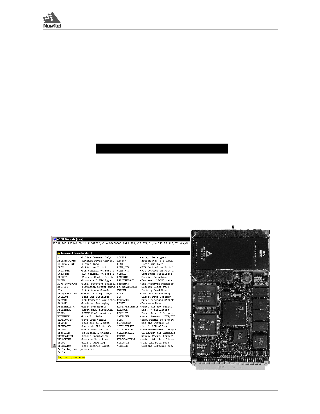
Graphical Interface
Your GPSCard comes with a disk containing NovAtel’s graphical interface software GPSolution, a Microsoft
Windows-based program , enabling you to us e your GP SCard w ithout s truggl ing wit h commun ications protoc ol or
writing make-do software.
MiLLennium GPSCard SW Version 4.503/4.52 Command Descriptions Manual Rev 2 13
Page 14
1 Quick Start
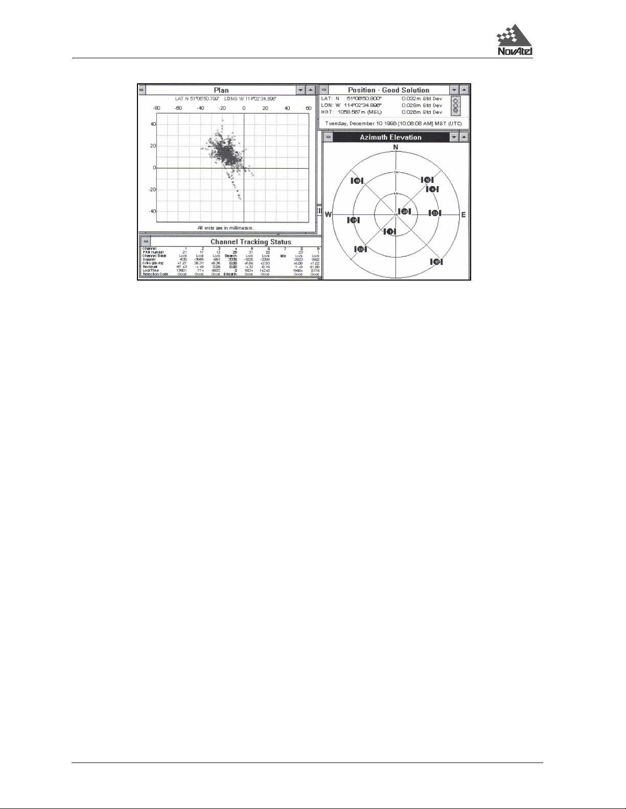
The View menu options allow you to select or de-select various visual aids and display screens. Take a look at all
of the options and keep open those you wish to display. To send commands and log data the Command Console
screen should be visible. ASCII format logs can be monitored on the ASCII Record screen.
e.g. On the command line of the Command Console screen type:
After you hit the <Enter> key the ASCII Record screen will display the output for your current position. The
POSA/B log is described on Page 180.
log com1 posa once
1.2 DATA LOGGING
The GPSCard has four major logging formats:
• NovAtel Format Data Logs (ASCII/Binary)
• NMEA Standard Format Data Logs (ASCII)
• RTCM Standard Format Data Logs (Binary)
• RTCA Standard Format Data Logs (Binary)
All data types can be logged using several methods of triggering each log event. Each log is initiated using the LOG
command. The LOG command and syntax are listed following.
14 MiLLennium GPSCard SW Version 4.503/4.52 Command Descriptions Manual Rev 2
Page 15

1 Quick Start
Syntax: log [port],datatype,[trigger],[period],[offset],{hold}
Syntax Description Example
LOG LOG
port COM1 or COM2 Defaults to the port that the command was entered on. COM1
datatype Enter one of the valid ASCII or Binary Data Logs (see Chapter 4, Page 35 and Appendix D, Page 138) POSA
trigger Enter one of the following triggers. ONTIME
ONCE Immediately logs the selected data to the selected port once. Default if trigger field is left
ONMARK Logs the selected data when a MARKIN electrical event is detected. Outputs internal buffers
ONNEW Logs the selected data each time the data is new even if the data is unchanged.
ONCHANGED Logs the selected data only when the data has changed.
ONTIME
[period], [offset]
CONTINUOUSLY Will log the data all the time. The GPSCard will generate a new log when the output buffer
period Use only with the ONTIME trigger. Units for this parameter are seconds. The selected period may be any of the
following values: 0.05, 0.10, 0.20, 0.25, 0.50, 1, 2, 3, ... , 3600 seconds but may be limited by the GPSCard model
and previously requested logs. Selected data is logged immediately and then periodic logging of the data will start
at the next even multiple of the period. If a period of 0.20 sec is chosen, then data will be logged when the receiver
time is at the 0.20, 0.40, 0.60 and the next (0.80) second marks. If the period is 15 seconds, then the logger will
log the data when the receiver time is at even 1/4 minute marks. The same rule applies even if the chosen period
is not divisible into its next second or minute marks. If a period of 7 seconds is chosen, then the logger will log at
the multiples of 7 seconds less than 60, that is, 7, 14, 21, 28, 35, 42, 49, 56 and every 7 seconds thereafter.
offset Use only with the ONTIME trigger. Units for this parameter are seconds. It provides the ability to offset the logging
events from the above startup rule. If you wished to log data at 1 second after every minute you would set the period
to 60 seconds and the offset to 1 second (Default is 0).
hold Will prevent a log from being removed when the UNLOGALL command is issued HOLD
blank.
at time of mark - does not extrapolate to mark time. Use MKPA/B for extrapolated position
at time of mark.
Immediately logs the selected data and then periodically logs the selected data at a
frequency determined by the period and offset parameters. The logging will continue until an
UNLOG command pertaining to the selected data item is received (see the UNLOG
command, Page 134).
associated with the chosen port becomes empty. The continuously option was designed for
use with differential corrections over low bit rate data links. This will provide optimal record
generation rates. The next record will not be generated until the last byte of the previous
record is loaded into the output buffer of the UART.
60
1
NOTE: The syntax for a command can contain option al parameters (OPT1, OP T2, ...). OPT2 may only be us ed if
it is preceded by OPT1. OPT3 may only be used if it is preceded by OPT2 and so on. Parameters after and
including OPT1 will be surrounded by square brackets.
An optional parameter such as {hold} surrounded by braces may be used with the log command without
any preceding optional parameters.
Example:
log com1 posa 60 1 hold
log com1 posa hold
Example:
log com1,posa,ontime,60,1
If the LOG syntax does not include a trigger type, it will be output only once following execution of the LOG
command. If trigger type is specified in the LOG syntax, the log will continu e to be output based on the trigger
specification. Specific logs can be disabled using the UNLOG command, whereas all enabled logs will be disabled
by using the UNLOGALL command (see Chapter 2, Page 24 and Appendix C, Page 81). All activated logs will
be listed in the receiver configuration status log (RCCA), Page 192.
The [port] parameter is optional. If [port] is not specified, [port] is defaulted to the port that the command was
received on.
MiLLennium GPSCard SW Version 4.503/4.52 Command Descriptions Manual Rev 2 15
Page 16

1 Quick Start
COMMONLY USED LOGS
Type Logs Trigger
Positioning PRTKA/B
POSA/B
Post Processing RGEA/B/D
REPA/B, ALMA/B
NMEA Position GPGLL
GPGGA
Other useful logs are
• RCCA to list the default command settings
• ETSA to monitor the channel tracking status
• SATA to obser ve the satellite specific data
• DOPA to monitor the dilution of precision of the current satellite constellation
• RVSA to monitor the receiver status
For further information on output logging see Chapter 4, Page 35 and the individual logs listed alphabetically in
Appendix D, Page 138.
Use the HELP command to list all available commands. For more info rmation on sending comm ands s ee Chapter
2, Page 24 and the individual commands listed alphabetically in Appendix C, Page 81.
ontime or onmark
ontime
onchanged
ontime or onmark
1.3 DIFFERENTIAL OPERATION
The MiLLennium GPSCard is ideal for design into DGPS systems because it is capable of operating as either a
reference station or a rover station.
The GPSCard is capable of utilizing various formats of differential corrections. These formats are divided into two
primary groups RTCM and RTCA.
For detailed data structure concerning these logs, please see:
Chapter 3, Page 35
Chapter 4, Page 46
Appendix D, Page 138
Establish a Data Link
Operating the GPSCard with a DGPS system requires that the reference station broadcast differential correction
data messages to one or more rover receivers. As there are many methods by which this can be achieved, it is up
to you to establish an appropriate data link that best suits your user requirements.
Whatever data link is chosen, the operator of the reference station will want to ensure that the bit rate of data
transmission is suitable for the an ticipated data lin k and remote u sers. Use the GPS Card COMn comm and to the
COM port default bit rate (default is 9600 bps, no parity, 8 data bits, 1 stop bit, no handshake, echo off).
Note that the GPSCard COMn_DTR and COMn_RTS commands are available for remote device keying (such as
a radio transmitter). These commands allow for flexible control of the DTR and RTS lines to be precisely timed
with log transmissions.
Further information may be found in Appendix A.
Table 1-1, following, is a GPSCard pseudorange differential initialization summary.
16 MiLLennium GPSCard SW Version 4.503/4.52 Command Descriptions Manual Rev 2
Page 17

Required:
Table 1-1 GPSCard Pseudorange Differential Initialization Summary
Reference Station Remote Station
FIX POSITION lat lon hgt id (health)
LOG port DATATYPE ontime 5
Required:
ACCEPT port DATATYPE
1 Quick Start
Recommended Options:
LOG DATATYPES (binary):
LOG DATATYPE S (asc ii):
RTCMB
RTCAB
RTCM
RTCA
RTCMA
RTCAA
Related Commands/Logs:
RTCMRULE
DATUM
Example 1:
fix position 51.3455323 -114.2895345 1201.123 555 0
log com 1 RTCM ontime 2
Example 2:
fix position 51.3455323 -114.2895345 1201.123 555 0
log com2 rtcaa ontime 2
Note: Italicized entries indicate user definable.
Recommended Options:
ACCEPT DATATYPES (binary):
ACCEPT COMMANDS (ascii):
Related Commands/Logs:
RTCMRULE
DATUM
POSA/B
VLHA/B
CDSA/B
GPGGA
Example 1:
accept com2 rtcm
log com1 posa ontime 1
Example 2:
accept com2 commands
log com1 posa ontime 0.2
log com1 vlha ontime 0.2
RTCM
RTCA
RTCMA
RTCAA
Initialization - Reference Station
Differential mode of operation is established at the reference station through a two step process: fix position and
logging observation and correction data.
FIX POSITION
The reference station must initialize the precise position of its reference antenna phase centre (lat/lon/hgt). This is
accomplished by utilizing the GPSCard FIX POSITION command. The syntax is as follows:
Syntax:
FIX POSITION lat lon height station id health
Example:
fix position 51.3455323,-114.2895345,1201.123,555,0
MiLLennium GPSCard SW Version 4.503/4.52 Command Descriptions Manual Rev 2 17
Page 18

1 Quick Start
NOTE 1: Entry of the station ID and health are optional. For a CMR correction type the station ID mu st b e < 31 .
NOTE 2: The accuracy of the reference station’s FIX POSITION setting will directly affect the accuracy of its
computed differential corrections. Good results at the rover station are dependent on the reference
station’s combined position errors being kept to a minimum (e.g., fix position error + multipath errors).
NOTE 3: The GPSCard performs all computations based on WGS84 and is defaulted as such, regardless of
DATUM command setting. The datum in which you choose to operate is converted from WGS84;
therefore, all differential corrections are based on WGS84. Ensure that any change in your operating
datum is set prior to FIX POSITION.
NOTE 4: When transmitting RTCM type data, the GPSCard has various options for assigning the number of data
bits per byte. Please see the GPSCard command RTCMRULE, Page 116 for further information
concerning RTCM data bit rule settings.
NOTE 5: The FIX POSITION “health” field entered will be reported in word 2 of the RTCM message frame
header.
Once the GPSCard has its position data fixed and is tracking th ree or more satellites, it is now ready to trans mit
differential correction and observation data to the rover stations.
LOG BROADCAST DATA
Assuming that a data link has been establi shed, use the GPSCard log command to send observation and di fferential
corrections data for broadcast to the rover stations.
Syntax:
LOG port data ontime seconds
Example:
log com1 rtcm ontime 5
NOTE: Ensure that the bit rate of the data link is suitable for the differential type, logging rate and maximum
message length of the data type being logged.
1.4 RTK MODE
NovAtel’s RTK system utilizes proprietary messaging as well as RTCM Types 18 and 19, and can also receive
CMR messages from a non-NovAtel base station. For more information on specific message formats please see
Chapter 4, Page 46.
NOTE: No guarantee is made that the MiLLennium will meet its performance specifications if non-NovAtel
accessories (e.g. antennas, RF cable) are used.
Data Communications Link
It is the user’s responsibility to provide a data communicatio ns link between the reference station and remote
station. The data transfer rate must be high enough to ensure that sufficient reference station messages reach the
remote station to keep extrapolation errors from growing too large; see Table 1-2.
Table 1-2 Latency-Induced Extrapolation Error
Time since last reference station observation Typical extrapolation error (CEP)
0-2 seconds 1 cm/sec
2-7 seconds 2 cm/sec
7-30 seconds 5 cm/sec
18 MiLLennium GPSCard SW Version 4.503/4.52 Command Descriptions Manual Rev 2
Page 19

1 Quick Start
Generally, a communications link capable of data throughput at a rate of 4800 bits per second or higher is
sufficient. However, it is possible to satisfactorily use a lower rate (e.g. 2400 bps) with the RTC A, RTCM 59 and
CMR formats. RTCM Types 18 and 19 may require a higher rate; see Chapter 4, Message Formats, Page 46 for
additional information. The minimum data transfer rate is based on the following :
1. RT-2 requires th at the reference station periodically transmit two RTCA Standard Type 7 messages:
• An RTCAOBS message contains reference station satellite observation information, and
should be se nt once every 1 or 2 seconds.
• An RTCAREF message contains reference station position information, and should be
sent once every 10 seconds.
OR periodically transmit an R TCM Type 18 and RTCM Type 19 (R TCM1819) me ssage together with an
RTCM Type 3 message:
• A Type 3 message contains reference station position information , and shou ld be sent
once every 10 seconds (although it is possible to send it as infrequently as once every 30
seconds).
• RTCM1819 gives raw measurement information (Type 18 provides carrier phase
measurements, while Type 19 provides pseudorange measurements) and should be sent
once every 1 or 2 seconds.
NOTE: This message can be sent in RT CM Version 2. 1 or Vers ion 2.2 fo rmat, contro lled with the RTKMODE
command.
and, optionally, also periodically transmit an RTCM Type 22 message together with an RTCM Type 3
message:
• A Type 3 message contains reference station position information , and shou ld be sent
once every 10 seconds (although it is possible to send it as infrequently as once every 30
seconds).
• A Type 22 message gives extended reference station parameters and should be sent once
every 10 seconds.
OR periodically transmit two CMR messages where the station ID, see Page 100, must be
transmitting CMR corrections:
• A CMROBS message contains reference station satellite observation information, and
should be se nt once every 1 or 2 seconds.
• A CMRREF message contains reference station position information, and should be sent
once every 10 seconds.
2. RT-20 requires that the reference station periodically transmit either the RTCA messages listed above (the
recommended option), or RTCM 1819 or CMR messages or the RTCM SC-104 Type 3 & 59N messages:
• A Type 3 message contains reference station position information , and shou ld be sent
once every 10 seconds (although it is possible to send it as infrequently as once every 30
seconds).
• A Type 59N message contains reference station satellite observ ation information, and
should be sent once every 2 seconds.
≤ 31 when
Further information on RTCA, RTCM and CMR message formats is contained in Chapter 6.
System Initiali za t ion
The RTK system is designed for ease of use: you set up the remote station, enter a command so that it accepts RT2 or RT-20 messages from the reference station, and are ready to go. There are options, however, which can be
used to adapt the system to a specific application. Some options apply only to the reference station, while others
MiLLennium GPSCard SW Version 4.503/4.52 Command Descriptions Manual Rev 2 19
Page 20

1 Quick Start
apply only to the remote station. Detailed descriptions can be found in Appendix C, Commands Summary.
In the following sections, keep the following in mind:
• Dynamics modes. For reliable performance the antenna should not move more than 1-2
cm when in static mode. See the RTKMODE commands in Chapter 2, Page 24 and
Appendix C, Page 117 for more information.
• When using the FIX POSITION command, the height entered must be in metres above
mean sea level; it will be converted to ellipsoidal height inside the receiver. You can enter
an undulation value, if desired, using the UNDULATION command; if none is entered,
the receiver estimates an undulation with its internal table. The format of the optional
station ID field depends on whether RTCM or R TC A mes sages ar e being us ed: if RTCM,
any number from 0 - 1023 is valid, while if RTCA, any 4-character string of numbers and
upper-case letters, enclosed in quotation marks, is valid. See Appendix C, Page 100 for
additional information on the station id field.
• The COMn field refers to the se rial por t (eit her COM1 or COM2) to which data
communications equipment is connected. The serial port assignment at the reference and
remote stations need not be the same; e.g. a radio transmitter might be connected to
COM1 at the reference station, and a radio receiver to COM2 at the remote station.
INITIALIZATION FOR RTCA-FORMAT MESSAGING (RT-2 OR RT-20)
The following commands will enable RTCA-format messaging and allow RT-2 or RT-20 to operate with the
remote station either at rest or in motion. Note that the optional station health field in the existing FIX POSITION
command is not currently implemented in NovAtel’s RTCA messages, though it will be in the future.
1. At the reference station:
fix position lat,lon,height,station id
log comn,rtcaref,ontime,interval
log comn,rtcaobs,ontime,interval
Example:
fix position 51.11358042,-114.04358013,1059.4105,”RW34”
log com1,rtcaref,ontime,10
log com1,rtcaobs,ontime,2
2. At the remote station:
accept comn,rtca
Example:
accept com2,rtca
Congratulations! Your RTK system is now in operation!
INITIALIZATION FOR RTCM59-FORMAT MESSAGING (RT-20 ONLY)
Although RT-20 can operate with either RTCA or RTCM-format messaging, the use of RTCA-format messages is
recommended (see Chapter 4, Page 46 for further information on this topic). Nevertheless, the following
commands will enable RTCM59-format messaging and allow RT-20 to operate with the remote station either at
rest or in motion:
1. At the reference station:
fix position lat,lon,height,station id,station health
log comn,rtcm3,ontime,interval
log comn,rtcm59,ontime,interval
20 MiLLennium GPSCard SW Version 4.503/4.52 Command Descriptions Manual Rev 2
Page 21

1 Quick Start
Example:
fix position 51.11358042,-114.04358013,1059.4105,119,0
log com1,rtcm3,ontime,10
log com1,rtcm59,ontime,2
2. At the remote station:
accept comn,rtcm
Example:
accept com2,rtcm
Congratulations! Your RT-20 system is now in operation!
Monitoring Your RTK Output Data
At the remote station, you could now select any or all of these output logs for positioning information:
• BSLA/B Baseline Measurement
• NMEA-format logs
• POSA/B Computed Position
• PRTKA/B Best Position
• RPSA/B Reference Station Position & Health
• RTKA/B RTK Output - Time Matched Positions
The POSA/B, PRTKA/B and NMEA-format logs contain the low-latency position; the RTKA/B logs co ntain the
matched position. The low-latency solution is the recommended one for kinematic users, while the matched
solution is the one recommended for stationary users. Fo r a discussion on low-latency and matched positions, see
the Differential Positioning section of Appendix A, Page 67.
Options for Logging Differential Corrections
SET DGPSTIMEOUT
The DGPSTIMEOUT command allows the reference station to set the delay by which it wil l inhibit utilization of
new ephemeris data in its differential corrections. This delay ensures that the remote receivers have had sufficient
time to collect updated ephemeris data as well.
A delay of 120 to 130 seconds will typically ensure that the rover stations have collected updated ephemeris. After
the delay period is pas sed, t he r eferen ce st at ion wi ll b egi n us ing n e w ephem eri s dat a. To ent er an ephemeris delay
value, you must first enter a numeric placeholder in the DGPS delay field (e.g., 2). When operating as a reference
station, DGPS delay will be ignored (see the DGPSTIMEOUT command found in Chapter 2, Page 24 and
Appendix C, Page 92 for further information on using this command at rover stations.)
Syntax:
DGPSTIMEOUT dgps delay ephem delay
Command Option Description Default
DGPSTIMEOUT Command
dgps delay min. 2
max. 1000
ephem delay min. 0
max. 600
Maximum age in seconds 60
Minimum time delay in seconds 120
Example:
dgpstimeout 2,300
MiLLennium GPSCard SW Version 4.503/4.52 Command Descriptions Manual Rev 2 21
Page 22

1 Quick Start
USING RTCM SC-104 LOG TYPES
RTCM SC-104 is a standard for transmitting differential corrections between equipment from different
manufacturers. The NovAtel GPSCard is capable of transmitting or receiving RTCM data.
To facilitate transmitting the RTCM data over shared data links, the GPSCard is also capable of sending the RTCM
log in NovAtel ASCII format (R TCMA) or with the NovA tel binary header (R TCMB) added to allow s ynchronous
transmission and reception along with other data types.
NOTE: When sending or receiving RTCM log types, it is important to ensure that all connected equipment are
using the same RTCMRULE for compatibility.
The easiest method to send RTCM standard lo gs is from the COM1 o r COM2 ports of the referen ce GPSCard. The
easiest method to receive the RTCM data is through the COM1 or COM2 port of the rover GPSCard. The rover
GPSCard must issue the “ACCEPT port RTCM” command to dedicate a port before it will accept the RTCM data
into that port.
The RTCMA log can be intermix ed with othe r NovAtel A SCII data over a common communication port. It will
be directly interpreted by a rover GPSCard as a special data input command ($RTCM). “ACCEPT port
COMMANDS” must be used with this input command. A non-NovAtel rover station will need to strip off the
header ($RTCM) and terminator (*xx), then con vert the hexadecimal data to binary befo re the RTCM standard data
can be retrieved.
The RTCMB log can be intermixed with other NovAtel binary data over a common communication port.
REMEMBER: Use the CDSA/B logs to monitor the COM port activity, success, and decoding errors.
USING RTCA LOG TYPES
The RTCA (Radio Technical Commission for Aviation Services) Standard is being designed to support
Differential Global Navigation Satellite System (DGNSS) aviation applications. The perceived advantage to using
RTCA type messages for transmitting and receiving differential corrections versus using RTCM type messages is
that RTCM transmits 30-bit words, and the data is difficult to decode and process because of the parity algorithm
and irregular word sizes used. RTCA is transmitted in 8-bit words, which are easier to generate, process and
decode. The RTCA messages are therefore smaller, they have a 24 bit CRC that is much more robust than RTCM
messages, and they permit the use of a four-alpha-character station ID.
RTCA standard logs can be received through the COM1 or COM2 port of the rover GPSCard. The remote
GPSCard must issue the “ACCEPT port RTCA” command to dedicate a port before it will accept the RTCA data
input to that port. The RTCA logs cannot be intermixed with other logs.
The RTCAA log can be intermixed with other NovAtel ASCII data over a common communications port. It will
be directly interpreted by a rover GPSCard as a special data input comman d ($RTCA). “ACCEPT po rt commands”
must be used with this input command. A non-NovAtel rover station will need to strip off the header ($RTCA) and
terminator (*xx), then convert the hexadecimal data to binary before the RTCA standard can be retrieved.
The RTCAB log can be intermixed with other NovAtel binary data. Th e remote GPSCard identifies the RTCAB
log by the message block identifier contained in the message, and will interpret only the RTCA data portion of the
log.
NOTE: The CDSA/B logs may be used to monitor the COM port activity and differential data decode success.
Initialization - Rover Station
It is necessary to initialize the rover receiver to accept observation data from the reference station. If the receiver
is not correctly initialized, it will proceed to compute solutions in single point positioning mode.
22 MiLLennium GPSCard SW Version 4.503/4.52 Command Descriptions Manual Rev 2
Page 23

1 Quick Start
Before initializing, ensure that the data link with the reference station has been properly set up. As well, ensure that
the COM port which is to receive the differential data is s et up to match th e bit rate and pr otocol settings of the
reference station broadcast data.
Establishing differential mode of operation at the rov er receiver is primarily a one- step process whereb y the accept
command is used to enable reception of observation data from the reference station.
ACCEPT COMMAND
The accept command is primarily used to set the GPSCard’s COM port command interpreter for acceptance of
various data formats (see the ACCEPT command in Chapter 2, Page 24 and Appendix C, Page 81).
Syntax
ACCEPT port mode
Example:
accept com2 rtcm
Once intitialized, the rover GPSCard receiver will operate in single point mode until the differential messages are
received. If the data messages are lost, the GPSCard will revert to single point positioning until the pseudorange
correction messages are restored.
NOTE: Ensure that the GPSCard RTCMRULE settings agree with the bit rule being transmitted by the RTCM
Range Value Default
reference station. Unless otherwise set, all GPSCards default to 6CR.
LOG POSITION DATA AND OTHER USEFUL DATA
The GPSCard remote receiver has many options for information data logging. To monitor position status, the user
may find the PRTKA/B logs to be the most informative. Other options exist, such as POSA/B and GPGGA. As
well, velocity data can be found in the VLHA/B, SPHA/B and GPVTG logs. It is really up to your specific
applications as to the full range of logs you require.
MiLLennium GPSCard SW Version 4.503/4.52 Command Descriptions Manual Rev 2 23
Page 24

2 Command Descriptions
2 COMMAND DESCRIPTIONS
2 COMMAND DESCRIPTIONS
2.1 GENERAL
This section describes all commands accepted by the GPSCard with the exception of the "Special Data Input
Commands". They are listed in alphabetical order. For descriptions of output logs using the LOG command, see
Chapter 3.
The GPSCard is capable of responding to over 50 different input commands. You will find that once you become
familiar with these commands, the GPSCard offers a wide range in operational f lexibility. All commands are
accepted through the COM1 and COM2 serial ports. See Table 2-1, Page 26 for a complete command listing.
NOTE: You will find the HELP command a useful tool for inquiring about the various commands available.
The following rules apply when entering commands from a terminal keyboard:
• The commands are not case sensitive (
e.g.
e.g.
HELP or help
FIX POSITION or fix position
COMMAND or command).
• All commands and required entries can be separated by a space or a comma
(command,variable
OR command variable).
e.g. datum,tokyo
e.g. datum tokyo
e.g. fix,position,51.3455323,-117.289534,1002
e.g. fix position 51.3455323 -117.289534 1002
e.g. com1,9600,n,8,1,n,off
e.g. com1 9600 n 8 1 n off
e.g. log,com1,posa,onchanged
e.g. log com1 posa unchanged
• At the end of a command or comm and strin g, p res s th e <CR> key. A carriage return is what
the card is looking for and is usually the same as pressing the <Enter> key.
• Most command entries do not provide a response to the entered command. Exceptions to
this statement are the VERSION and HELP commands. Otherwise, successful entry of a
command is verified by receipt of the COM port prompt (i.e. COM1> or COM2>).
The syntax for a command can contain optional parameters (OPT1, OPT2, ...). OPT2 may only be used if it
is preceded by OPT1. OPT3 may only be used if it is preceded by OPT2 and so on. Parameters after and
including OPT1 will be surrounded by square brackets.
An optional parameter such as {hold} surrounded by braces may be used with the log without any preceding
optional parameters
Example:
log com1 posa 60 1 hold
log com1 posa hold
When the GPSCard is first powered up, or after a FRESET command, all commands will rev ert to the factory
default settings. An example is shown below. The SAVECONFIG command can be used to modify the power-on
defaults. Use the RCCA log to reference stati on comm a nd and log settings.
24 MiLLennium GPSCard SW Version 4.503/4.52 Command Descriptions Manual Rev 2
Page 25

2 Command Descriptions
NOTE: All previously stored configurations that were saved to non-volatile memory are erased (including
Saved Config, Saved Almanac, and Channel Config).
Example:
Optional Calculation Of The Checksum
When an input command is followed by an optional checksum, the checksum will be verified before the command
is executed. The checksum is the result of the logical exclusive-OR operation on all the bits in the message. So, the
checksum of a command with parameters will change if the parameters are modified.
NOTE: The command must be typed in uppercase for the proper checksum to be calculated.
As an example, it may be essential to ensure that a receiver has received and executed the correct command from
a host computer. If the checksum were calculated by the sender and attached to the command, the receiver would
be able to recognize if errors had been introduced and if so, alert the sender to this with an “Invalid Command
CRC” message.
Example:
FIX HEIGHT 4.567[CR][LF]
FIX HEIGHT 4.567*66[CR][LF]
Both are acceptable, but only the second one would trigger the verification function.
MiLLennium GPSCard SW Version 4.503/4.52 Command Descriptions Manual Rev 2 25
Page 26

2 Command Descriptions
2.2 STANDARD COMMAND TABLES
Table 2-1 lists the commands by function while Table 2-2 is an alphabetical listing of commands. Please see
Appendix C, Page 81 for a more detailed description of individual commands which are listed alphabetically.
Table 2-1 Commands By Function Table
COMMUNICATIONS, CONTROL AND STATUS
Commands Descriptions
ANTENNAPOWER Power to the low-noise amplifier of an active antenna
COMn COMn port configuration control
COMn_DTR DTR handshaking control
COMn_RTS RTS handshaking control
DIFF_PROTOCOL
FREQUENCY_OUT Variable frequency output (programmable )
LOG Logging control
MESSAGES Disable error reporting fro m comm an d in terpre te r
RINEX Configure the user defined fiel ds in t he file header
RTCMRULE Sets up RTCM bit rule
RTCM16T Enters an ASCII message
SEND Sends ASCII message to COM port
SENDHEX Sends non-printable characters
SETL1OFFSET
1 Intended for advanced users of GPS only
1
1
Differential Protocol Control
Add an offset to the L1 pseudorange to compensate for
signal delays
GENERAL RECEIVER CONTROL AND STATUS
Commands Descriptions
$ALMA Download almanac data file
CRESET Reset receiver to factory default
DYNAMICS Set correlator tracking bandwidth
HELP On-line command help
RESET Performs a hardware reset (OEM only)
SAVEALMA Saves the latest almana c in NVM
SAVECONFIG Sav es current configuration (OEM onl y)
$TM1A Injects receiver time of 1PP S
VERSION Software/hardware information
26 MiLLennium GPSCard SW Version 4.503/4.52 Command Descriptions Manual Rev 2
Page 27

Table 2-1 Commands By Function Table (continued)
POSITION, PARAMETERS, AND SOLUTION FILTERING CONTROL
Commands Descriptions
CSMOOTH
DATUM Choose a DATUM na me type
ECUTOFF Satellite elevation cut-off for solutions
FIX HEIGHT C onstrains to fixed height (2D mode)
FIX POSITION Constrains to fixed lat, lon, height
FRESET Clears all data which is stored in NVM
$IONA Download ion osphe ric correction data
IONOMODEL
LOCKOUT Deweights a satellite in solutions
$PVAA
RTKMODE Setup the RTK mode
UNDULATION Ellipsoid-geoid separation
USERDATUM User-customized datum
WAASCORRECTION Controls handling of WAAS/EGNOS corrections.
1 Intended for advanced users of GPS only.
1
1
Sets amount of carrier smoot hi ng
What ionospheric correction to use (MiLLennium with the
WAAS option)
Position, velocity and accel e rat ion in ECEF coordinates
2 Command Descriptions
SATELLITE TRACKING AND CHANNEL CONTROL
Commands Descriptions
$ALMA Download almanac data file
ASSIGN Satellite channel assignment
CONFIG Switc hes the channel configuratio n of th e G PSCard
DYNAMICS Sets correlator tracking band w idth
FIX VELOCITY Aids high ve l ocity reacqu i s ition
RESETHEALTH Reset PRN health
SETHEALTH Overrides broadcast satellite health
WAYPOINT NAVIGATION
Commands Descriptions
MAGVAR Magnetic variation correction
SETNAV Waypoint input
DIFFERENTIAL REFERENCE STATION
Commands Descriptions
DGPSTIMEOUT Sets ephemeris del ay
FIX POSITION Constrain to fixed (reference)
LOG Selects required differential-output log
POSAVE Implements position averagi ng for reference station
RTCMRULE Selects RTCM bit rule
SETDGPSID Set reference station ID
MiLLennium GPSCard SW Version 4.503/4.52 Command Descriptions Manual Rev 2 27
Page 28

2 Command Descriptions
Table 2-1 Commands By Function Table (continued)
DIFFERENTIAL REMOTE STATION
Commands Descriptions
ACCEPT Accepts RTCM1, RTCA or RTCA B di fferential inputs
$ALMA Input almanac data
DGPSTIMEOUT Set maximum age of differential data accepted
RESET Performs a hardware reset
$RTCA RTCA differential correct io n input (ASCII)
$RTCM RTCM differential correction in put (A SCII)
RTCMRULE Selects RTCM bit rule
SETDGPSID Select differential referen ce stat io n ID to rec ei ve
CLOCK INFORMATION, STATUS, AND TIME
Commands Descriptions
CLOCKADJUST Enable clock modelling & 1PPS adjust
1
DIFF_PROTOCOL
EXTERNALCLOCK Sets default parameters of an optional external oscillator
EXTERNALCLOCK FREQUENCY Sets clock rate
SETTIMESYNC
$UTCA Download UTC data
Differential protocol control
1
Enable or disable time syn ch ronization
1 Intended for advanced users of GPS only
Table 2-2 GPSCard Command Summary
Command Description Syntax
$ALMA Injects almanac (follows NovAtel ASCII log format)
$IONA Injects ionospheric refract ion corrections (follows NovAtel ASCII log format)
$PVAA Injects latest computed position, velocity and acceleration (follows NovAtel ASCII log format)
$REPA Injects raw GPS ephemeris data (follows NovAtel ASCII log format)
$RTCA Injects RTCA format DGPS corrections in ASCII (Type 1) (follows NovAtel ASCII log format)
$RTCM Injects RTCM format differential corrections in ASCII (Type 1) (follows NovAtel ASCII log format)
$TM1A Injects receiver time of 1 PPS (follows NovAtel ASCII log format)
$UTCA Injects UTC information (follows NovAtel ASCII log format)
ACCEPT Port input control (set command interpreter) accept port,option
ANTENNAPOWER Power to the low-noise amplifier of an active antenna antennapower flag
ASSIGN Assign a prn to a channel # assign channel,prn,doppler, search window
UNASSIGN Un-assign a channel unassign channel
UNASSIGNALL Un-assign all channels unassignall
CLOCKADJUST Disable clock steering mechanism clockadjust switch
COMn Initialize Serial Port (1 or 2) comn bps,parity,databits,stopbits, handshake,echo
COMn_DTR Programmable DTR lead/tail time comn_dtr control,active,lead,tail
COMn_RTS Programmable RTS lead/tail time comn_rts control,active,lead,tail
CONFIG Switches the channel configuration of the GPSCard config cfgtype
CRESET Configuration reset to factory default creset
CSMOOTH Sets carr ier smo oth ing csmooth value
DATUM Choose a DATUM name type datum option
USERDATUM User defined DATUM userdatum semi-major,flattening,dx,dy,dz, rx,ry,rz,
DGPSTIMEOUT Sets maximum age of differential data to be accepted and ephemeris
delay
scale
dgpstimeout value value
28 MiLLennium GPSCard SW Version 4.503/4.52 Command Descriptions Manual Rev 2
Page 29

2 Command Descriptions
DIFF_PROTOCOL Diffe ren tial cor rect ion messa ge enc odi ng and decod ing for
DYNAMICS Set receiver dyna mics dynamics option [user_dynamics]
ECUTOFF Set elevation cutoff angle ecutoff angle
EXTERNALCLOCK Sets default parameters of an optional external oscillator externalclock option
EXTERNALCLOCK
FREQUENCY
FIX HEIGHT Sets height for 2D navigation fix height height [auto]
FIX POSITION Set antenna coordinates for reference station fix position lat,lon,height [station id] [health]
FIX VELOCITY Accepts INS xyz (ECEF) input to aid in high velocity reacquisition of
UNFIX Remove all receiver FIX constraints unfix
FREQUENCY_OUT Variable frequency output (programmable) frequency_out n,k
FRESET Clears all data which is stored in non-volatile memory freset
HELP or ? On-line command help help option or ? option
IONOMODEL Influences what ionospheric corrections the card uses ionomodel keyword
LOCKOUT Lock out satellite lockout prn
UNLOCKOUT Restore satellite unlockout prn
UNLOCKOUTALL Restore all satellites unlockoutall
LOG Choose data logging type log [port],datatype,[trigger],[period],[offset],{hold}
UNLOG Disable a data log unlog [port],data type
UNLOGALL Disable all data logs unlogall [port]
MAGVAR Set magnetic variation correction magvar value
MESSAGES Disable error reporting from command inte rpre ter messages port,option
POSAVE Implements position averaging for reference station posave maxtime, maxhorstd, maxverstd
RESET Performs a hardware reset (OEM only) reset
RINEX Configure the user defined fields in the file headers rinex cfgtype
RTCM16T Enter an ASCII text message to be sent out in the RTCM data stream rtcm16t ascii message
RTCMRULE Set variations of the RTCM bit rule rtcmrule rule
RTKMODE Set up the RTK mode rrtkmode argument, data range
SAVEALMA Save the latest almanac in non-volatile memory savealma option
SAVECONFIG Save current configuration in non-volatile memory (OEM only) saveconfig
SEND Send an ASCII message to any of the communications ports send port ascii-message
SENDHEX Sends non-printable characters in hexadecimal pairs sendhex port data
SETDGPSID Enter in a reference station ID setdgpsid option
SETHEALTH Override PRN health sethealth prn,health
RESETHEALTH Reset PRN health resethealth prn
RESETHEALTHALL Reset all PRN health resethealthall
SETL1OFFSET Add an offset to the L1 pseudorange to compensate for signal delays setL1offset distance
SETNAV Set a destination waypoint setnav from lat,from lon,to lat, to lon,track offset, from
SETTIMESYNC Enable or disable ti me synchronization settimesync flag
UNDULATION Choose undulation undulation separation
VERSION Current software and hardware information version
WAASCORRECTION Dictates how the card handles WAAS/EGNOS corrections waascorrection keyword [prn] [mode]
implementation in the GPS card firmware
Sets clock rate external frequency clock rate
SVs
diff_protocol type key
or diff_protocol disable
or diff_protocol
fix velocity vx,vy,vz
port,to port
MiLLennium GPSCard SW Version 4.503/4.52 Command Descriptions Manual Rev 2 29
Page 30
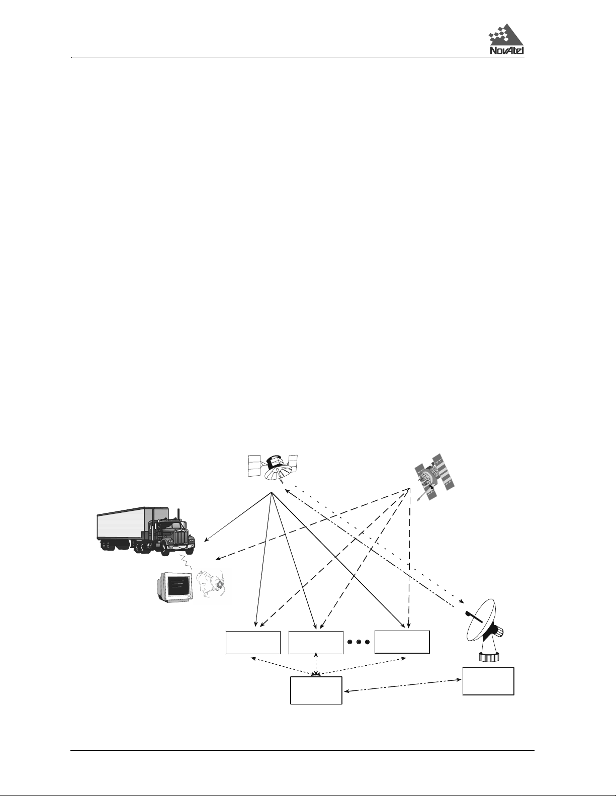
2 Command Descriptions
Gro
u
S
Integrity data,differential corrections
,
time control, and statu
s
PS Satellit
eConstellationIntegrity da
ta,differential
c
and ranging
C-ban
d
tio
n
2.3 WAAS
The Wide Area Augmentation System (WAAS) is a safety-critical system that provides a quality of positioning
information previously unavailable. The WAAS improves the accuracy, integrity, and availability of the basic GPS
signals. In the future, the wide area of coverage for this system will include the entire United States and some
outlying areas. At the time of publication, there are two WAAS satellites over the western Atlantic Ocean and the
Pacific (PRN 122 and PRN 134 respectively) and one EGNOS satellite over the eastern Atlantic Ocean (PRN 120).
WAAS data is available from any of these satellites and more satellites will b e available in the fu ture.
The primary functions of WAAS include:
• data collection
• determining ionospheric corrections
• determining satellite orbits
• determining satellite clock corrections
• determining satellite integrity
• independent data verification
• WAAS message broadcast and ranging
• system operations & maintenance
As shown in Figure 2-1, the WAAS is made up of a series of Wide Area Reference Stations, Wide Area Master
Stations, Ground Uplink Stations and Geostationary Satellites (GEOs). The Wide Area Reference Stations, which
are geographically distributed, pick up GPS satellite data and route it to the Wide Area Master Stations where wide
area corrections are generated. These corrections are sent to the Ground Uplink Stations which up-link them to the
GEOs for re-transmission on the GPS L1 frequency. These GEOs transmit signals which carry accuracy and
integrity messages, and which also provide additional ranging signals for added availability, continuity and
accuracy. These GEO signals are available over a wide area and can be received and processed by ordinary GPS
receivers. GPS user receivers are thus able to receive WAAS data in-band and use not only differential corrections,
but also integrity, residual errors and ionospheric information for each monitored satellite.
GPS User
Figure 2-1 The WAAS Concept
Geostationary
Satellite (GEO)
L1
Wide-area
Refere nce Sta t ion
(WRS)
L1 & C-band
Wide-area
Refere nce Sta t ion
(WRS)
Wide-area
Master Station
(WMS)
L1 & L2
Wide-area
Reference Sta
(WRS)
G
orrections,
control
nd Uplink
tation
(GUS)
30 MiLLennium GPSCard SW Version 4.503/4.52 Command Descriptions Manual Rev 2
Page 31

2 Command Descriptions
The signal broadcast via the WAAS GEOs to the WAAS users is designed to minimize modifications to standard
GPS receivers. As such, the GPS L1 frequency (1575.42 MHz) is used, together with GPS-type modulation - e.g.
a Coarse/Acquisition (C/A) pseudorandom (PRN) code. In addition , the code phase timin g is maintained clos e to
GPS time to provide a ranging capability.
2.3.1 WAAS GPSCard
The MILLEN-STDW, MILLEN-3111W and MILLEN-3151W models o f the MiLLennium GPSCard are equ ipped
with the WAAS/EGNOS option. The ability to incorporate the WAAS/EGNOS corrections into the position is the
default mode for these models.
NovAtel has developed several models of WAAS-capable MiLLennium GPSCards that process WAAS signals.
These models can output the WAAS data in log format (FRMA/B, WALA/B), and can incorporate these
corrections to generate differential-quality position solutions. The WAAS/EGNOS models permit two userconfigurable options: 12 GPS (10 Hz position and r aw data output rate) or 10 GPS and 1 WAAS L1 channels (2
Hz output). The second configuration is the default for WAAS/EGN OS models. The first is invoked with the
CONFIG command (see Page 88) and resets the card. Standard WAAS/EGNOS data messages are analyzed based
on RTCA standard DO-229B Change 1 Minimum Operational Performance Standards for GPS/WAAS airborne
equipment.
A WAAS/EGNOS-capable MiLLennium GPSCard will permit anyone within the area of coverage to take
advantage of its benefits. In addition, it has all the features of a standard MiLLennium GPSCard.
WAAS COMMANDS
Two commands, WAASCORRECTION and IONOMODEL (see their descriptions on Page 137 and Page 105
respectively), enable the use of the WAAS corrections in the position filter. In order to use these commands, first
ensure that your GPSCard is capable of receiving WAAS corrections.
2.4 SPECIAL DATA INPUT COMMANDS
These entries are data messages that are generated by one GPSCard and sent to another. For example, consider a
special configuration in which a GPSCard #1 is able to send these data messages to a GPSCard #2 via a serial port.
For GPSCard #1, this is no different than sending these data messages to a file or a screen. Each of these data
messages has a special header which is interpreted by GPSCard #2 to mean that the data in that message is to be
used as an update of its own GPS parameters such as time, position, velocity, acceleration or knowledge of satellite
ephemeris.
In this general category also belo ng the RTCM data mes sages ($RTCM1A, $RTCM3A, $RTCM9 A, $RTCM16A,
and $RTCM59A). These are described in further detail in Chapter 4, Message Formats.
The injection of special command data can take place via COM1 or COM2. Remember, the source of these special
data commands are valid NovAtel ASCII data logs.
The special data commands fall into two categories: Almanac Data and Differential Corrections.
2.4.1 Almanac Data
The GPSCard’s standard features include almanac data collection. Following a cold-start boot-up or system reset,
the GPSCard will begin a sky search. Once a valid satellite is acquired, the GPSCard will begin almanac
downloading and decoding. This process will take at least 12.5 minutes following the cold-start (assuming there
are no problems with satellite visibility or the antenna system). It is noted that Ionospheric Correction Data and
UTC data are also collected at the same time as almanac data and will also be available following the 12.5 minutes
collection period mentioned above.
12 channel OEM cards with the SAVECONF IG option will automatically save almanacs in their non-volatile
memory. They will also automatically load the last saved almanac following a cold start or a reset. The card will
save an almanac and ionospheric and UTC data received from a satellite if there is no current data in non-volatile
memory (NVM), or if the GPS week number of the received data is newer than the week number of the data in
NVM. The save will not occur until b etween 12.5 and 25 minutes hav e elapsed since the last reset. To check if
almanac data is saved in the NVM of the OEM card, check the "almanac data saved" bit in the receiver status word.
See the description of the RCSA/B logs, Appendix D, Page 193 for details.
MiLLennium GPSCard SW Version 4.503/4.52 Command Descriptions Manual Rev 2 31
Page 32

2 Command Descriptions
The GPSCard is capable of logging almanac data utilizing the NovAtel-format ASCII log command option ALMA.
Once logged, the data records will precede the header with the $ character (e.g., $ALMA).
There are no specific NovAtel log option commands to independently specify output of ionospheric or UTC
parameters. These parameters will always output followin g the $ALMA log (identifiabl e by the headers $IONA
and $UTCA respectively). See Chapter 3 and Appendix D, Page 138 for more information on the ALMA output
log command option.
The GPSCard has the capability to accept injection of previously logged NovAtel-format ASCII almanac data
($ALMA, $IONA, and $UTCA). The GPSCard will interpret th is log data as s pecial data input commands. This
provides the user with the advantage of being able to inject recent almanac data following a cold-start or RESET
without having to wait the 12.5 minutes described in above paragraphs.
There are various ways by which this can be accomplished.
• By connecting the COM1 or COM2
port from one GPSCard (reference) directly to the
COM1 or COM2 port of another GPSCard (remote). The reference card is assumed to be
tracking satellites for some time and can be commanded by th e ALMA log comma nd opti on
to output almanac records to the remote card. The remote card can be assumed to be just
powered-up or RESET and will recognize the $ALMA, $IONA, and $UTCA data as special
input commands and update its almanac tables with this new data.
NOTE: When connecting two GPSCard COM ports together, the MESSAGES comm and op tio n sh ould be set
to "OFF" to prevent inter-card "chatter".
• The MiLLennium GPSCard can log current almanac data to a PC conn ected to its COM1 o r
COM2 port. Assuming the PC is correctly configured using terminal emulator
communications software, then the PC can redirect the GPSCard almanac log to its disk
storage device. At a later time following a system restart, the GPSCard can have this
almanac.dat file (containing $ALMA, $IONA, and $UTCA records) immediately
downloaded as a special input command for immediate use. Refer to the MiLLEnnium
GPSCard Guide to Instal l ati on and Operat i ng manual for more information about
interfacing with the OEM card with a PC. [Note: this procedure will generally not be
required with OEM cards as all 12 channel cards now have an almanac save feature built in
using non-volatile memory.]
$ALMA...
Use this special data input command to quickly update the GPSCard almanac tables following a system restart. It
is generated from a GPSCard ALMA log and is accepted as the following format:
$ALMA,1,3.55148E-003,552960,744,-7.8174E-009,6.10457691E-002,-1.1820041E+000,
1.90436112E+000,-1.8119E-005,-3.6379E-012,1.45854758E-004,2.65602532E+007,
9.55600E-001,1,0,0*0C
...
(one record for each valid satellite)
...
$ALMA,31,4.90379E-003,552960,744,-7.9660E-009,-3.1044479E+000,6.13853346E-001,
1.92552900E+000,6.67572E-006,3.63797E-012,1.45861764E-004,2.65594027E+007,
9.61670E-001,1,0,0*3F
$IONA...
Use this special data input command to quickly update the GPSCard ionospheric corrections tables following a
system restart (always appended to $ALMA records unless intentionally s tripped). This data will ensure that the
initial position solutions computed by the GPSCard are as accurate as possible. It is generated from a GPSCard
ALMA log and is accepted by any GPSCard as the following format:
$IONA,1.0244548320770265E-008,1.4901161193847656E-008,-5.960464477539061E-008,
-1.192092895507812E-007,8.8064000000000017E+004,3.2768000000000010E+004, -
1.966080000000001E+005,-1.966080000000001E+005*02
32 MiLLennium GPSCard SW Version 4.503/4.52 Command Descriptions Manual Rev 2
Page 33

2 Command Descriptions
$UTCA...
Use this special data input command to quickly update the GPSCard Universal Time Coordinated (UTC)
parameters following a system restart (always append ed to $ALMA records unless intentionally stripped). The
UTC data is required before the GPSCard can accurately compute UTC time. If not input with $UTCA, it may take
up to 12.5 minutes after a reset for the GPSCard to receive current UTCA data. In order to comply with NMEA
standards, the GPSCard will null NMEA log data fields until valid UTC parameters ar e collected or injected by the
$UTCA input command. This command is generated from a GPSCard ALMA log and is accepted as the following
format:
$UTCA,-1.769512891769409E-008,-1.776356839400250E-015,552960,744,755,9,10,5*03
2.4.2 Differential Corrections Data
NovAtel MiLLennium cards can utilize the special data input commands $RTCA and $RTCM. These special data
input commands are utilized by a GPSCard operating as a remote station to accept NovAtel ASCII format
differential corrections. The data is generated by a GPSCard operating as a reference station with intent to be
received by remote stations. To correctly interpret these commands, the remote GPSCard must have its ACCEPT
command option set to "COMMANDS" (default). See Appendix A, Page 67 for furth er inf ormation on differ enti al
positioning.
$PVAA/B XYZ POSITION, VELOCITY AND ACCELERATION
The $PVAA and PVAB data messages contain the receiver’s latest computed position, velocity and acceleration.
These quantities are in rectangular ECEF coordinates based on the centre of the WGS-84 ellipsoid.
When a GPSCard receives this data message, it uses the information to update its own position, velocity and
acceleration parameters. This would only be needed if the GPSCard could not compute its own position, velocity
and acceleration due to signal blockage. This data message helps the receiver reacquire satellites after loss of lock.
The data would aid the receiver channels in the re-acquisition process; thus, the receiver would “follow” the
blocked satellites and re-acquire them much more quickly when they become visible again.
The position, velocity and acceleration status fields indicate whether or not the corresponding data are valid. Only
those messages containing valid data are used by the GPSCard.
NOTE 1: This command is intended for applications involving very high dynamics - where significant position,
velocity and acceleration changes can occur during a signal blockage. This data message helps the
receiver reacquire satellites after loss of lock.
NOTE 2: This is a highly complex function, to be used only by advanced users.
The ASCII $PVAA data message is generated from a PVAA log, and the binary PVAB data message is generated
from a PVAB log. For descriptions of these data messages, please see the description of the PVAA/B logs in
Chapter 4, Page 35 and Appendix D, Page 183. An example of a $PVAA data message is as follows:
$PVAA,845,344559.00,-1634953.141,-3664681.855,4942249.361,-0.025,0.140,
0.078,0.000,-0.000,0.000,1,1,1*02
$REPA/B RAW GPS EPHEMERIS DATA
In cases where the receiver does not have an ephemeris for a newly-viewed satellite, t hese data messages can be
used to reduce the time required to incorporate this satellite into the position solut ion
The $REPA and REPB data messages contain the raw binary information for subframes one, two and three from
the satellite with the parity information removed. Each subframe is 240 bits long (10 words - 25 bits each) and the
log contains a total 720 bits (90 bytes ) of information (240 bits x 3 subfram es). This information is preceded by the
PRN number of the satellite from which it originated. This message will not be generated unless all 10 words from
all 3 frames have passed parity.
The ASCII $REPA data message is generated from a REPA log, and the binary REPB data message is generated
from a REPB log. For descriptions of these data messages, please see the description of the REPA/B logs in
MiLLennium GPSCard SW Version 4.503/4.52 Command Descriptions Manual Rev 2 33
Page 34

2 Command Descriptions
Chapter 3 and Appendix D, Page 194. An example of a $REPA data message is as follows:
$REPA,14,8B09DC17B9079DD7007D5DE404A9B2D04CF671C6036612560000021804FD,
8B09DC17B98A66FF713092F12B359DFF7A0254088E1656A10BE2FF125655,
8B09DC17B78F0027192056EAFFDF2724C9FE159675A8B468FFA8D066F743*57[CR][LF]
$RTCA... (RTCAA)
Use this special data input command to directly input NovAtel RTCAA differential corrections data, ASCII format.
The data can be accepted using COM1 or COM2. The differential corrections will be accepted and applied upon
receipt of this special data input command.
The data is generated from a GPSCard RTCAA log and is accep ted by a GPSCard remote station as in the fo llowing
format:
$RTCA,990000000447520607BE7C92FA0B82423E9FE507DF5F3FC9FD071AFC7FA0D207D090808C0E
045BACC055E9075271FFB0200413F43FF810049C9DFF8FFD074FCF3C940504052DFB*20
$RTCM... (RTCMA, $RTCM1A, $RTCM3A, $RTCM9A, $RTCM16A,$RTCM59A)
Use this special data input command to directly input RTCMA differential correction data, ASCII format (RTCM
data converted to ASCII hexadecimal, with NovAtel header added). The data can be accepted using COM1
COM2. The differential corrections will be accepted and applied upon receipt of this special data input co mmand .
See RTCA Standard Logs on Page 47 for further information on RTCM related topics.
The data is generated from a GPSCard RTCMA log and is accepted by a GPSCard remote station as in the
following format
or
$RTCM,664142404E7257585C6E7F424E757D7A467C47414F6378635552427F73577261624278777F
5B5A525C7354527C4060777B4843637C7F555F6A784155597D7F6763507B77496E7F7A6A426F555C
4C604F4E7F467F5A787F6B5F69506C6D6A4C*2B
NOTE: The $RTCAA and $RTCMA commands allow the user to intermix differential corrections along with
other ASCII commands or logs over a single port. (You must, however, ensure that the ACCEPT
command option is set to “COMMANDS”.)
TIP: The decoding success and status of $R TCA and $RTCM records can be monitored us ing the C DSA/B
data log. These commands will not generate any reply response from the command interpreter. They
will simply be processed for valid format and checksum and used internally. If there is any problem
with the data, characters missing or checksum fail, the data will be discarded with no warning message.
$TM1A/B RECEIVER TIME OF 1PPS
The $TM1A and TM1B data messages can be used to time-synchronize multiple receivers which are all referencing
the same external oscillator. First, ensure that SETTIMESYNC is enabled. Next, the primary unit must be sending
its 1PPS signal to the MARKIN input of the s econdary unit. Third, the two units must be commu nicating via a
COM port. In this configurat ion, the u ser can s end t he $T M1A lo g from a prim ary to a s econdary unit, i n a manner
similar to that for $ALMA or $UTCA. The secondary unit is then able to compare the time information contained
in the log with that of the 1PPS signal, and set its clock even though it may not be tracking any satellites.
The ASCII $TM1A data message i s gen erat ed f rom a TM1A log, and the binary TM1B data mes sage i s gener at ed
from a TM1B log. For descriptions of these data messages, please see the description of the TM1A/B logs in
Chapter 4, Page 35 and Appendix D, Page 220. An example of a $TM1A data message is as follows:
$TM1A,794,414634.999999966,-0.000000078,0.000000021,-.999999998,0*57[CR][LF]
The $TM1A/B message refers to the 1PPS pulse which has just occurred. In other words TM1A comes after a 1PPS
pulse. The length of the pulse for the 24 channel L1/L2 MiLLennium GPSCard is a normally high , active low pulse
(1 millisecond), where falling edge is reference.
34 MiLLennium GPSCard SW Version 4.503/4.52 Command Descriptions Manual Rev 2
Page 35

3 Data Logs
3 DATA LOGS
3 DATA LOGS
3.1 OUTPUT LOGGING
The GPSCard provides versatility in your logging requirements. You can direct your logs to either COM 1 or
COM2, or both ports, as well as combine data types. The GPSCard has four major logging formats:
• NovAtel Format Data Logs (ASCII/Binary)
• NMEA Standard Format Data Logs (ASCII)
• RTCM Standard Format Data Logs (Binary)
• RTCA Standard Format Data Logs (Binary)
All data types can be logged using several methods of triggering each log event. Each log is initiated using the LOG
command. The LOG command and syntax are listed below.
Syntax:
log [port],datatype,[trigger],[period],[offset],{hold}
Syntax Description Example
LOG LOG
port COM1 or COM2 COM1
datatype Enter one of the valid ASCII or Binary Data Logs (see later in this chapter and Appendix D, Page 138) POSA
trigger Enter one of the following triggers. ONTIME
ONCE Immediately logs the selected data to the selected port once. Default if trigger field is left blank.
ONMARK Logs the selected data when a MARKIN electrical event is detected. Outputs internal buffers
at time of mark - does not extrapolate to mark time. Use MKBA/B for extrapolated position at
time of mark.
ONNEW Logs the selected data each time the data is new even if the data is unchanged.
ONCHANGED Logs the selected data only when the data has changed.
ONTIME
[period], [offset]
CONTINUOUSLY Will log the data all the time. The GPSCard will generate a new log when the output buffer
period Use only with the ONTIME trigger. Units for this parameter are seconds. The selected period may be any of the
following values: 0.05, 0.10, 0.20, 0.25, 0.50, 1, 2, 3, ... , 3600 seconds but may be limited by the GPSCard model
and previously requested logs. Selected data is logged immediately and then periodic logging of the data will start at
the next even multiple of the period. If a period of 0.20 sec is chosen, then data will be logged when the receiver time
is at the 0.20, 0.40, 0.60 and the next (0.80) second marks. If the period is 15 seconds, then the logger will log the
data when the receiver time is at even 1/4 minute marks. The same rule applies even if the chosen period is not
divisible into its next second or minute marks. If a period of 7 seconds is chosen, then the logger will log at the
multiples of 7 seconds less than 60, that is, 7, 14, 21, 28, 35, 42, 49, 56 and every 7 seconds thereafter.
offset Use only with the ONTIME trigger. Units for this parameter are seconds. It provides the ability to offset the logging
events from the above startup rule. If you wished to log data at 1 second after every minute you would set the period
to 60 seconds and the offset to 1 second (Default is 0).
hold Will prevent a log from being removed when the UNLOGALL command is issued HOLD
Example:
log com1,posa,ontime,60,1
Immediately logs the selected data and then periodically logs the selected data at a frequency
determined by the period and offset parameters. The logging will continue until an UNLOG
command pertaining to the selected data item is received (see UNLOG Command, Page 134).
associated with the chosen port becomes empty. The continuously option was designed for
use with differential corrections over low bit rate data links. This will provide optimal record
generation rates. The next record will not be generated until the last byte of the previous record
is loaded into the output buffer of the UART.
60
1
If the LOG syntax does not include a trigger type, it will be output only once following execution of the LOG
command. If trigger type is specified in the LOG syntax, the log will continu e to be output based on the trigger
MiLLennium GPSCard SW Version 4.503/4.52 Command Descriptions Manual Rev 2 35
Page 36

3 Data Logs
specification. Specific logs can be disabled using the UNLOG command, whereas all enabled logs will be disabl ed
by using the UNLOGALL command (see Chapter 2, Page 24 and Appendix C, Page 134). All activated logs will
be listed in the receiver configuration status log (RCCA).
3.2 NOVATEL FORMAT DATA LOGS
General
The GPSCard is capable of executing more than 4 0 NovAtel format log commands. Each log is selectable in ASCII
and Binary formats. The one exception to this rule is the RGE log, which can be logged as RGED. The “D”
indicates a compressed binary format to allow higher speed logging. Any format can be selected individually or
simultaneously over the same COMn ports.
All of the log descriptions are listed in alphabetical order in Appendix D. Each log first lists the ASCII format,
followed by the Binary format description.
ASCII Log Structure
Log types ending with the letter A (or a) will be output in ASCII format (e.g., POSA). The structures of all ASCII
logs follow the general conventions as noted here:
1. The lead code identifier for each record is '$'.
2. Each log is of variable length depending on amount of data and formats.
3. All data fields are delimited by a comma ',' with the exception of the last data field, which is followed by
a * to indicate end of message data.
4. Each log ends with a hexadecimal number preceded by an asterisk and fo llowed by a line termination using the carriage return and line feed characters, e.g., *xx[CR][LF]. This 8-bit value is an exclusive OR
(XOR) of all bytes in the log, excluding the '$' identifier an d the asterisk preceding the two checksum digits.
Structure:
$xxxx, data field..., data field..., data field... *xx [CR][LF]
Binary Log Structure
Log types ending with the letter B (or b) will be output in Binary format (e.g., POSB). The structures of all Binary
logs follow the general conventions as noted here:
1. Basic format of: Sync 3 bytes
Checksum 1 byte
Message ID 4 bytes unsigned integer
Message by te count 4 bytes unsigned integer
Data x
2. The Sync bytes will always be:
Byte Hex Decimal
First AA 170
Second 44 68
Third 11 17
3. The Checksum is an XOR of all the bytes (including the 12 header bytes) and is initially set to 00.
4. The Message ID identifies the type of log to follow.
5. The Message byte count equals the total length of the data block including the header.
NOTE: Maximum flexibility for logging data is provided to the user by these logs. The user is cautioned,
however, to recognize that each log requested requires add itional CPU time and memory bu ffer space.
Too many logs may result in lo st data and degraded CPU performance. CPU overload can be monitored
using the idle-time and buffer overloa d bits from the RCSA/B log. See Table D-5, Pag e 198 (GPSCard
Receiver Self-test Status Codes).
36 MiLLennium GPSCard SW Version 4.503/4.52 Command Descriptions Manual Rev 2
Page 37

3 Data Logs
The following table describes the format types used in the description of binary logs.
Type Size (bytes) Size (bits) Description
char 1 8 The char type is used to store the integer value of a member of the representable character
int 4 32 The size of a signed or unsigned int item is the standard size of an integer on a particular
double 8 64 The double type contains 64 bits: 1 for sign, 11 for the exponent, and 52 for the mantissa.
float 4 32 The float type contains 32 bits: 1 for the sign, 8 for the exponent, and 23 for the mantissa.
set. That integer value is the ASCII code corresponding to the specified character.
machine. On a 32-bit processor (such as the NovAtel GPSCard), the int type is 32 bits, or 4
bytes. The int types all represent signed values unless specified otherwise. Signed integers
are represented in two’s-complement form. The most-significant bit holds the sign: 1 for
negative, 0 for positive and zero.
Its range is ±1.7E308 with at least 15 digits of precision.
Its range is ±3.4E38 with at least 7 digits of precision.
Each byte within an int has its own address, and the smallest of the addresses is the address of the int. The byte at
this lowest address contains the eight least significant bits of the doubleword, while the byte at the highest address
contains the eight most significant bits. The followin g illustration shows th e arrangement of bytes within wo rds
and doublewords. Similarly the bits of a "double" type are stored least significant byte first. This is the same data
format used by IBM PC computers.
70
char
address n
int
31
23
15 7 0
two’s
complement
n+3 n+2 n+1 address n
double
62 55 4751 39 31 23
Biased
S
Exponent
52-bits mantissa
15 7
63 52
float
n+7 n+6 n+5 n+4 n+3 n+2 n+1
30
Biased
S
Exponent
31
n+3
22 15 7
23-bits mantissa
23
n+2 n+1 address n
0
address n
0
0
3.3 RTK
After setting up your system and initializing the positioning algorithms, as described in the RTK section of Chapter
1. Yo u can use the logs listed in this section to record the data collected. The low-latency-solution logs (e.g.
PRTKA/B) are recommended for kinematic users, while the matched-solution logs (e.g. RTKA/B) are
recommended for stationary users. For a discussion on low-latency and matched solutions, see the Differential
Positioning section in Appendix A, Page 67.
A matched solution is always a carrier-phase differential solution, and consequently offers the greatest possible
accuracy. A low-latency solution, on the other hand, is the best one that is currently available; the possibilities are
categorized as follows, starting with the one offering the greatest accuracy and precision:
1. Carrier-phase differential solution
2. Pseudorange differential solution
3. Single-point solution
Therefore, if an RTK solution is not available, then a low-latency-solution log will contain a pseudorange
differential solution if it exists. If neith er an RTK nor a pseudorange differential solution is available, then a lowlatency-solution log will contain a single-point solution.
MiLLennium GPSCard SW Version 4.503/4.52 Command Descriptions Manual Rev 2 37
Page 38

3 Data Logs
3.4 NMEA FORMAT DATA LOGS
General
The NMEA log structures follow format standards as adopted by the National Marine Electronics Association. The
reference document used is "Sta nd ard For Interfacing Marine Electroni c Devi ces NM EA 0 183 V ers ion 2 .00". For
further information, see Appendix F, Standards and References, Page 239. The following table contains excerpts
from Table 6 of the NMEA Standard which defines the variables for the NMEA logs. The actual format for each
parameter is indicated after its description.
Field Type Symbol Definition
Special Format Fields
Status A Single character field:
A = Yes, Data Valid, Warning Flag Clear
V = No, Data Invalid, Warning Flag Set
Latitude llll.ll Fixed/Variable length field:
degrees|minutes.decimal - 2 fixed digits of degrees, 2 fixed digits of minutes and a variable
digits for decimal-fraction of minutes. Leading zeros always included for degrees and minutes to
maintain fixed length. The decimal point and associated decimal-fraction are optional if full resolution is
not required.
Longitude yyyyy.yy Fixed/Variable length field:
degrees|minutes.decimal - 3 fixed digits of degrees, 2 fixed digits of minutes and a variable number of
digits for decimal-fraction of minutes. Leading zeros always included for degrees and minutes to
maintain fixed length. The decimal point and associated decimal-fraction are optional if full resolution is
not required
Time hhmmss.ss Fixed/Variable length field:
Defined field Some fields are specified to contain pre-defined constants, most often alpha characters. Such a field is
Numeric Value Fields
hours|minutes|seconds.decimal - 2 fixed digits of hours, 2 fixed digits of minutes, 2 fixed digits of
seconds and variable
for hours, minutes and seconds to maintain fixed length. The decimal point and associated decimalfraction are optional if full resolution is not required.
indicated in this standard by the presence of one or more valid characters. Excluded from the list of
allowable characters are the following which are used to indicate field types within this standard:
"A", "a", "c", "hh", "hhmmss.ss", "llll.ll", "x", "yyyyy.yy"
number of digits for decimal-fraction of seconds. Leading zeros always included
number of
Variable
numbers
Fixed HEX field hh___ Fixed length HEX numbers only, MSB on the left
Information Fields
Variable text c--c Variable length valid character field.
Fixed alpha field aa___ Fixed length field of uppercase or lowercase alpha characters
Fixed number xx___ Fixed length field of numeric characters
Fixed text field cc___ Fixed length field of valid characters
1. Spaces may only be used in variable text fields.
2. A negative sign "-" (HEX 2D) is the first character in a Field if the value is negative. The sign is omitted if value is positive.
3. All data fields are delimited by a comma (,).
4. Null fields are indicated by no data between two commas (,,). Null fields indicate invalid or no data available.
5. The NMEA Standard requires that message lengths be limited to 82 characters.
x.x Variable length integer or floating numeric field. Optional leading and trailing zeros. The decimal point
and associated decimal-fraction are optional if full resolution is not required (example: 73.10 = 73.1 =
073.1 = 73)
NOTES:
3.5 GPS TIME VS. LOCAL RECEIVER TIME
All logs report GPS time expressed in GPS weeks and seconds into the week. The time reported is not corrected
for local receiver clock error. To derive the closest GPS time, one must subtract the clock offset shown in the
38 MiLLennium GPSCard SW Version 4.503/4.52 Command Descriptions Manual Rev 2
Page 39

3 Data Logs
CLKA log (field 4) from GPS time reported.
GPS time is based on an atomic time scale. Universal Time Coordinated (UTC) time (reported in NMEA logs) is
also based on an atomic time scale, with an offset of seconds applied to coordinate Universal Time to GPS time.
GPS time is designated as being coinc ident with UTC at t he start date of January 6, 19 80 (00 hours ). GPS time does
not count leap seconds, and therefore an offset exists between UTC and GPS time. The GPS week consists of
604800 seconds, where 000000 seconds is at Saturday midnight. Each week at this time, the week number
increments by one, and the seconds into the week resets to 0. (See Appendix H, Some Co m mon Unit Conversions,
Page 242 for an example)
3.6 STANDARD LOG TABLES
Table 3-1 lists the logs by function while Table 3-2 is an alphabetical listing of logs. Please see Appendix D, Page
138 for a more detailed description of in divi du al No vAte l and NM EA for mat logs w hich are l is ted alphabetically.
RTCM and RTCA format data logs and receiver-independent RINEX logs w ill be found in Chapter 4. Special
Pass-Through logs are found in Section 3.8.
Table 3-1 Logs By Function Table
COMMUNICATIONS, CONTROL AND STATUS
Logs Descriptions
CDSA/B COM port communications status
COM1A/B Log data from COM1
COM2A/B Log data from COM2
COMnA/B Pass-through data logs
RCSA/B Receiver self-test status
RTCM16T NovAtel ASCII forma t spe cial me ssage
RTCM16 RTCM format special message
GENERAL RECEIVER CONTROL AND STATUS
Logs Descriptions
PVAA/B Receiver’s latest computed position, veloc it y and acceleration in ECE F coordinates
RCCA Receiver configuration status
RCSA/B Version and self-test status
RVSA/B Receiver status
VERA/B Receiver hardware and software version num bers
POSITION, PARAMETERS, AND SOLUTION FILTERING CONTROL
Logs Descriptions
DOPA/B DOP of SVs cu rrently trac k ing
GGAB GPS fix data
GPGGA NMEA, position dat a
GPGLL NMEA, position data
GPGRS NMEA, range residuals
GPGSA NMEA, DOP information
GPGST NMEA, measurement noise statistic s
MKPA/B Position at time of mark
POSA/B Position data
PRTKA/B Computed position
PVAA/B Computed position, velocity and acceleration in ECEF c oordinates
PXYA/B Position (Cartesian x,y,z coo rdi na te s)
RTKA/B Computed position
SPHA/B Speed and direction over ground
MiLLennium GPSCard SW Version 4.503/4.52 Command Descriptions Manual Rev 2 39
Page 40

3 Data Logs
Table 3-1 Logs By Function Table (continued)
SATELLITE TRACKING AND CHANNEL CONTROL
Logs Descriptions
ALMA/B Curre nt de coded almanac data
DOPA/B DOP of SVs currently tracking
ETSA/B Provides channel tracking status information for each of the GPSCard parallel channels
GPALM NMEA, almanac data
GPGSA NMEA, SV DOP information
GPGSV NMEA, satellite-in-view info rm ation
RALA/B Raw almanac
RASA/B Raw GPS almanac set
RGEA/B/D Satellite ra n g e measurem ents
SATA/B Satellite specific information
SBTA/B Satellite broadca s t d ata (raw symb o ls)
SVDA/B SV position (E CE F xyz)
WALA/B W AAS Almanac
WRCA/B W id e ba nd range correction data (grouped format)
WAYPOINT NAVIGATION
Logs Descriptions
GPRMB NMEA, waypoint sta tus
GPRMC NMEA, navigation in form ation
GPVTG NMEA, tr ack made good and speed
GPZTG NMEA, time to destination
MKPA/B Position at time of mar k inp ut
NAVA/B Navigation waypoint status
POSA/B Position data
SPHA/B Speed and course over ground
VLHA/B Velocity, latency & direction over ground
DIFFERENTIAL REFERENCE STATION
Logs Descriptions
ALMA/B Current almanac information
CDSA/B COM port data transmission status
CMR Pseudorange and carrier phase data
PAVA/B Parameters being used in the position averaging proce ss
RGEA/B/D Channel range measurements
RPSA/B Reference station position and heal th
RTCAA/B Transmits RTCA differential corre ct ion s in Nov A te l ASC II or Bi na ry
RTCM1 Transmits RTCM SC104 standard corrections
RTCM3 Reference position
RTCM1819 Uncorrected carrier phase and pseudorange measurements
RTCM22 Extende d reference station paramete rs
RTCM59 NovAtel format RT-20 observation data
RTCMA/B Transm its RTCM informa tion in NovAte l A S CII/binary
SATA/B Satellite specific information
40 MiLLennium GPSCard SW Version 4.503/4.52 Command Descriptions Manual Rev 2
Page 41

Table 3-1 Logs By Function Table (continued)
DIFFERENTIAL REMOTE STATION
Logs Descriptions
CDSA/B Communication and differential decode status
GPGGA NMEA, position fix data
GGAB NovAtel binary version of GPGGA
POSA/B Position in f or mation
PRTKA/B Computed Position – best available
RTKA/B Computed Position – Time Matched
RTKOA/B RTK Output
SATA/B Satellite specific information
SVDA/B SV position in ECEF XYZ wit h corrections
VLHA/B Velocity, latency & direction over gro und
POST PROCESSING DATA
Logs Descriptions
BSLA/B Most recent matched baseline expr essed in ECEF coords.
CLKA/B Receiver clock offset information
REPA/B Raw ephemeris information
RGEA/B/D Satellite and ranging information
SATA/B Satellite specific information
SVDA/B SV position in ECEF XYZ wit h corrections
WEPA/B WAAS ephemeris information
3 Data Logs
CLOCK INFORMATION, STATUS, AND TIME
Logs Descriptions
CLKA/B Receiv er clock offset information
CLMA/B
GPZDA NMEA, UTC time and date
GPZTG NMEA, UTC and time to waypoint
MKTA/B Time of mark input
TM1A/B Time of 1PPS
WUTCA/B WAAS, UTC time parameters
1 Intended for advance d users of GPS only.
1
Current clock-model ma t r ic es of the GPSCard
NAVIGATION DATA
Logs Descriptions
FRMA/B Framed raw navigation data
RALA/B Raw almanac and heal th dat a
RASA/B Raw almanac set
RBTA/B Satellite broadcast data in raw bits
REPA/B Raw ephemeris data
MiLLennium GPSCard SW Version 4.503/4.52 Command Descriptions Manual Rev 2 41
Page 42

3 Data Logs
Table 3-2 GPSCard Log Summary
Syntax: log port,datatype,[trigger],[period],[offset],{hold}
NovAtel Format Logs
Datatype Description Datatype Description
ALMA/B Decoded Almanac RCCA Receiver Configuration
BSLA/B Baseline Measurement RCSA/B Receiver Status
CDSA/B Communication and Differential Decode Status REPA/B Raw Ephemeris
CLKA/B Receiver Clock Offset Data RGEA/B/D Channel Range Measurements
CLMA/B Receiver Clock Model RPSA/B Reference Station Position and Health
COM1A/B Log data from COM1 RTCAA/B RTCA format Differential Corrections with NovAtel
COM2A/B Log data from COM2 RTKA/B Computed Position - Time Matched
DOPA/B Dilution of Precision RTKOA/B RTK Solution Parameters
ETSA/B Extended Tracking Status RTCMA/B RTCM Type 1 Differential Corrections with NovAtel
FRMA/B Framed Raw Navigation Data RTCM16T Special Message
GGAB Global Position System Fix Data - Binary Format RVSA/B Receiver Status
MKPA/B Mark Position SATA/B Satellite Specific Data
MKTA/B Time of Mark Input SBTA/B Satellite Broadcast Data (Raw Symbols)
NAVA/B Navigation Data SPHA/B Speed and Direction Over Ground
PAVA/B Positioning Averaging Status SVDA/B SV Position in ECEF XYZ Coordinates with
POSA/B Computed Position TM1A/B Time of 1PPS
PRTKA/B Computed Position VERA/B Receiver Hardware and Software Version Numbers
PVAA/B XYZ Position, Velocity and Acceleration VLHA/B Velocity, Latency, and Direction over Ground
PXYA/B Computed Cartesian Coordinate Position WALA/B WAAS Almanac
RALA/B Raw Almanac WEPA/B WAAS Ephemeris
RASA/B Raw GPS Almanac Set WRCA/B Wide Band Range Correction (Grouped)
RBTA/B Satellite Broadcast Data: Raw Bits WUTCA/B WAAS, UTC Time Parameters
NMEA Format Logs
GPALM Almanac Data GPGSV GPS Satellites in View
GPGGA Global Position System Fix Data GPRMB Generic Navigation Information
GPGLL Geographic Position - lat/lon GPRMC GPS Specific Information
GPGRS GPS Range Residuals for Each Satellite GPVTG Track Made Good and Ground Speed
GPGSA GPS DOP and Active Satellites GPZDA UTC Time and Date
GPGST Pseudorange Measurement Noise Statistics GPZTG UTC & Time to Destination Waypoint
RTCA Format
RTCA RTCA Differential Corrections: Type 1 and Type 7
RTCM Format
RTCM1 Type 1 Differential GPS Corrections
RTCM3 Type 3 Reference Station Parameters
RTCM9 Type 9 Partial Satellite Set Differential Corrections
RTCM16 Type 16 Special Message
RTCM1819 Type 18 and Type 19 Uncorrected Carrier Phase and Pseudorange Corrections
RTCM22 Type 22 Extended Reference Station Parameters
RTCM59 Type 59N-0 NovAtel Proprietary Message: RT20 Differential Observations
Note: A/B/D:
headers
headers
Corrections
42 MiLLennium GPSCard SW Version 4.503/4.52 Command Descriptions Manual Rev 2
Page 43

3 Data Logs
A refers to GPSCard output logs in ASCII format.
B refers to GPSCard output logs in Binary format.
D refers to GPSCard output logs in compressed binary format.
3.7 WAAS
The Wide Area Augmentation System (WAAS) is a safety-critical system that provides a quality of positioning
information previously unavailable. The W AAS improves the accuracy, integr ity, and availability of the b asic GPS
signals.
3.7.1 WAAS GPSCard Logs
The log WALA/B (see its desc ripti ons on Page 224), provide WAAS satellite-specific data. For more information
on MiLLennium GPSCards with the WAAS option, see Page 30.
3.8 PASS-THROUGH LOGS
The pass-through logging feature enables the GPSCard to redirect any ASCII or binary data that is input at a
specified port (COM1 or COM2) to any specified GPSCard port (COM1 or COM2). This capability, in conjunction
with the SEND command, can allow the GPSCard to perform bi-directional communications with other devices
such as a modem, terminal, or another GPSCard.
There are two pass-through logs
Pass-through is initiated the same as any other l og, i.e., LOG [to-port] [ data-type-A/B] [trigger]. However, pass-
through can be more clearly specified as: LOG [to-port] [from-port-A/B] [onchanged]. Now, the [from-port-A/B]
field designates the port which accepts data (i.e., COM1or COM2) as well as the format in which the data will be
logged by the [to-port] — (A for ASCII or B for Binary).
When the [from-port-A/B] field is designated with an [A], all data received by that port will be redirected to the
[to-port] in ASCII format and will log according to standard NovAtel ASCII format. Therefore, all incoming
ASCII data will be redirected and output as ASCII data. However, any binary data received will be converted to a
form of ASCII hexadecimal before it is logged.
When the [from-port-A/B] field is designated with a [ B], all data received by that port will be redirected to the [toport] exactly as it is received. The log header and time-tag adhere to standard NovAtel Bina ry Format followed by
the pass-through data as it was received (ASCII or binary).
Pass-through logs are best utilized by setting the [trigger] field as onchanged or onnew. Eit her of these two
triggers will cause the incoming data to log when any one of the following conditions is met:
• Upon receipt of a <CR> character
• Upon receipt of a <LF> character
• Upon receipt of 80 characters
• 1/2 second timeout following receipt of last character
Each pass-through record transmitted by the GPSCard is time tagged by the GPSCard clock in GPS weeks and
seconds.
COM1A/B and COM2A/B, available on MiLLennium GPSCards.
For illustration purposes, you could connect two GPSCards together via their COM1 ports such as in a reference
station, labelled as reference station in Figure 3-1, to remote station scenario. If the reference station were logging
PVAA data to the remote station, it would be possible to use the pass-through logs to pass through the received
PVAA differential correction data to a disk file (let's call it DISKFILE.log) at the remote station host PC hard disk.
MiLLennium GPSCard SW Version 4.503/4.52 Command Descriptions Manual Rev 2 43
Page 44

3 Data Logs
Figure 3-1 Pass-Through Log Data
A
A
V
d
P
a
$
t
a
l
o
g
Data Link
To COM1
To COM1
Host PC
(Rover Station)
To COM2
Serial Cable
fix position (lat,lon,ht,id)
accept com1 none
log com1 pvaa ontime 5
Host PC
(Reference Station)
To COM2
Serial Cable
messages com1 off
log console com1a onchanged
When pass-through logs are being u sed, the GPSCard’s command interpreter continues to monitor the port for valid
input commands and replies with error messages when the data is not recognized as such. If you do not want the
pass-through input port to respond with error messages during unrecognized data input, see the MESSAGES
command, Appendix C, Page 110 for details on how to inhibit the port’s error message responses. As well, if you
do not want the reference station to accept any input from the remote device, use the ACCEPT NONE command
to disable the port’s command interpreter.
3.8.1 Command Syntax
Syntax:
log to-port from-port-A/B trigger
Syntax Range Value Description Default
log — Log command unlogall
to-port COM1, COM2 Port that will output the pass-through log data —
from-port-[A/B] COM1A/B, COM2A/B Port that will accept input data;
[A] option logs data as ASCII,
[B] option logs data with binary header
trigger onchanged or onnew log will output upon receipt of:
<CR>, <LF>, 80 characters, or 1/2 sec. timeout
Example 1:
—
—
log com2 com1a onchanged
3.8.2 ASCII Log Structure
$port ID week seconds pass-through data *xx [CR][LF]
Field # Field t ype Data Description Example
1 $port ID Log header:
Identifies port accepting input data
2 week GPS week number 747
3 seconds GPS seconds into the week at time of log 347131.23
4 pass-through data Data accepted into COM1
(up to 80 characters)
5 *xx Checksum *2E
6 [CR][LF] Sentence terminator [CR][LF]
44 MiLLennium GPSCard SW Version 4.503/4.52 Command Descriptions Manual Rev 2
$COM1
$TM1A,747,347131.000000000,
0.000000058,0.000000024,
-9.000000009,0*78<CR>
Page 45

3 Data Logs
Example 1:
$COM1,747,347131.23,$TM1A,747,347131.000000000,0.000000058,0.00000
0024, -9.000000009,0*78<CR>*2E[CR][LF]
$COM1,747,347131.31,<LF>*4F[CR][LF]
$COM1,747,347131.40,Invalid Command Option<LF>*7C[CR][LF]
$COM1,747,347131.42,Com1>Invalid Command Option<LF>*30[CR][LF]
$COM1,747,347131.45,Com1>*0A[CR][LF]
Example 1, above, shows what would result if a GPSCard logged TM1A data into the COM1 port of another
GPSCard, where the accepting card is redirecting this input data as a pas s-through log to its COM2 port (log com2
com1a onchanged). Under default conditions the two cards will "chatter" back and forth with the Invalid
Command Option message (due to the command interpreter in each card not recognizing the command prompts
of the other card). This chattering will in turn cause the accepting card to transmit new pass-through logs with the
response data from the other card. To avoid this chattering problem, use the GPSCard MESSAGES command on
the accepting port to disable error reporting from the r eceiving port command interpreter or if the incoming data is
of no use to the GPSCard, then disable the command interpreter with the ACCEPT NONE command.
If the accepting port’s error reporting i s disabl ed by ME SSAGES O FF, the $TM1A data record woul d pass t hrough
creating two records as follows:
Example 1a:
$COM1,747,347204.80,$TM1A,747,347203.999999957,-
0.000000015,0.000000024,
-9.000000009,0*55<CR>*00[CR][LF]
$COM1,747,347204.88,<LF>*48[CR][LF]
The reason that two records are logged from the accepting card is because the first record was initiated b y receipt
of the $TM1A log’s first terminator <CR>. Then the second record followed in response to the $TM1A log’s second
terminator <LF>.
Note that the time interval between the first character received ($) and the terminating <LF> can be calculated by
differencing the two GPS time t ags (0.08 seconds). This pass-throu gh feat u re i s usefu l for ti me ta gg ing t he arr iva l
of external messages. These messages could be any user-related data. If the user is using this feature for tagging
external events then it is recommended that the command interpreter be disabled so that the GPSCard does not
respond to the messages. See the ACCEPT command in Chapter 2, Page 24 and Appendix C, Page 81.
Example 1b illustrates what would result if $TM1B binary
log data were input to the accepting port
(i.e., log com2 com1a onchanged).
Example 1b:
$COM1,747,349005.18,<AA>D<DC1>k<ETX><NUL><NUL><NUL>4<NUL><NUL><NUL>
<EB><STX><NUL><NUL><FE>3M<NAK>A<VT><83><D6>o<82><C3>Z<BE><FC><97>I
<91><C5>iV><7F><8F>O<NUL><NUL><NUL>"<C0><NUL><NUL><NUL><NUL>*6A
As can be seen, the $TM1B binary data at the accepting port was converted to a variation of ASCII hexadecimal
before it was passed through to COM2 port for logging (MESSAGES command set to OFF).
3.8.3 Binary Log Structure
Format: Message ID = 30 for COM1B; 31 for COM2B
Message byte count = 24 + (length of pass-through data string received (80 maximum))
Field # Data Bytes Format Units Offset
1 Sync 3 char 0
(header) Checksum 1 char 3
Message ID 4 integer 4
Message byte count 4 integer 8
2 Week number 4 integer weeks 12
3 Seconds of week 8 double seconds 16
4 Pass-through data as
received
variable char 24 + (variable data)
MiLLennium GPSCard SW Version 4.503/4.52 Command Descriptions Manual Rev 2 45
Page 46

4 Message Formats
4 MESSAGE FORMATS
4 MESSAGE FORMATS
In a NovAtel RTK positioning system, the observatio ns transmitted by a NovAtel reference station to a NovAtel
remote station can be in either a proprietary RTCA Type 7 or a proprietary RTCM Type 59N message format. A
NovAtel Rover station is also able to receive CMR-format messages, Section 4.3, from a non-NovAtel base station.
Table 4-1 illustrates the various combinations of hardware and message formats, together with the position ing
mode (RT-20 or RT-2) which will result when using all-NovAtel devices:
Table 4-1 Positioning Modes
Remote station: L1
Remote station: L1 & L2
Reference station:
L1
RTCM Type 59N
RT-20 RT-20 RT-20 RT-20
RT-20 RT-20 RT-20 RT-2
Reference station:
L1
RTCA Type 7
Reference station:
L1 & L2
RTCM Type 59N
Reference station:
L1 & L2
RTCA Type 7
The following information can be used to calculate the minimum data throughput required of the communications
data link. Keep in mind that manufacturers of communication equipment add extra bits to each message (e.g. for
error detection), forming an “overhead” that must be taken into account; also, radio transmitting equipment may
have a duty cycle which must also be factored into the calculations. Thus, a “4800 bits per second” radio mode m
might actually sustain only 2000 bits per second. Cons ult the docu mentati on suppli ed by th e manufacturer o f your
communications equipment.
4.1 RTCA-FORMAT MESSAGES
NovAtel has defined two proprietary RTCA Standard Type 71 binary-format messages RTCAOBS and
RTCAREF, for reference station transmissions. These can be used with either single or dual-frequency NovAtel
receivers; existing users of RT-20 wishing to switch from RTCM to RTCA message formats will require a software
upgrade. The RTCA message format outperforms the RTCM format in the following ways, among others:
• a more efficient data structure (lower overhead)
• better error detection
• allowance for a longer message, if necessary
RTCAREF and RTCAOBS, respectively, correspond to the RTCM Type 3 and Type 59 logs used in singlefrequency-only measurements. Both are NovAtel-proprietary RTCA Standard Type 7 messages with an ‘N’
primary sub-label.
RTCAOBS TYPE 7
An RTCAOBS (RTCA Reference-Station Satellite Observations) message contains reference station satellite
observation information. It is used to provide range observations to the remote receiver, and should be sent every
1 or 2 seconds. This log is made up of variable-length messages up to 255 bytes long. The maximum number of
bits in this message is [140 + (92 x N)], where N is the maximum number of satellite record entr ies transmitted.
Using the RTKMODE command, you can define N to be anywhere from 4 to 20; the default value is 12.
1. For further information on RTCA Standard Type 7 messages, you may wish to refer to:
Minimum Aviation System Performance Standards - DGNSS Instrument Approach System: Special
Category I (SCA T-I), Document No. RTCA/DO-217 (April 19,1995); Appendix A, Page 21.
46 MiLLennium GPSCard SW Version 4.503/4.52 Command Descriptions Manual Rev 2
Page 47

4 Message Formats
RTCAREF TYPE 7
An RTCAREF (RTCA Reference Station Position Information) message contains reference station position
information, and should be sent once every 10 seconds. Each message is 24 bytes (192 bits) long.
If RTCA-format messaging is being used, the optional station id field that is entered using the FIX POSITION
command can be any 4-character string combining numbers and upper-case letters, and enclosed in quotation
marks (e.g. “RW34”). Note that the representation of this string in the log message would be a number within the
range of 266,305 to 15,179,385 as per RTCA notation. The lower bound of 266,305 represents “AAAA” and the
upper bound of 15,179,385 represents “9999”.
RTCA Standard Logs
The RTCA (Radio Technical Commission for Aviation Services) Standard is being designed to support
Differential Global Navigation Satellite System (DGNSS) Special Category I (SCAT-I) precision instrument
approaches. The RTCA Standard is in a preliminary state. Described below is NovAtel’s current support for this
Standard. It is based on "Minimum Aviation System Performance Standards DGNSS Instrument Approach
System: Special Category I (SCAT-I)" dated August 27, 1993 (RTCA/DO-217).
RTCA
This log enables transmission of RTCA Standard format T ype 1 messag es from the GPSCard when o perating as a
reference station. Before this message can be transmitted, the GPSCard FIX POSITION command must be set. The
RTCA log will be accepted by a GPSCard operating as a remote statio n over a COM p ort after an ACCEPT port
RTCA command is issued.
The RTCA Standard for SCAT-I stipulates that the maximum age of differential correction (Type 1) messages
accepted by the remote station cannot be greater than 22 seconds. See the DGPSTIMEOUT command in Chapter
2, Page 24 and Appendix C, Page 92 for information regarding DGPS delay settings.
The RTCA Standard also stipulates that a r eference station s hall wait five minutes after receiv ing a new ephemeris
before transmitting differential corrections. See the DGPSTIMEOUT command for information regarding
ephemeris de lay settings.
The basic SCAT-I Type 1 differential correction message is as follows:
Format: Message length = 11 + (6*obs): (83 bytes maximum)
Field Type Data Bits Bytes
SCAT-I header – Message block identifier
Type 1 header – Modified z-count
Type 1 data – Satellite ID
CRC Cyclic redundancy check 3
1 The pseudorange correction and range rate correction fields have a range of ±655.34 meters and ±4.049 m/s respec-
tively. Any satellite which exceeds these limits will not be included.
– Reference station ID
– Message type
(this field will always report 00000001)
– Message length
– Acceleration error bound
(In the GPSCard, this field will report
000)
– Pseudorange correction
– Issue of data
– Range rate correction
– UDRE
1
1
8
24
8
8
13
3 2
6
16
8
12
6
6
6 *obs
RTCAA
This log contains the same data available in the RTCA SCAT-I message, but has been modified to allow flexibility
in using the RTCA data. The RTCA data has been reformatted to be available in AS CII hexadecim al, utilizing a
NovAtel header and terminates with a checksum.
MiLLennium GPSCard SW Version 4.503/4.52 Command Descriptions Manual Rev 2 47
Page 48

4 Message Formats
This message was designed so that RTCA data can be intermixed with other NovAtel ASCII data over a common
communications port. The log is not in pure RTCA format. The header (
$RTCA) and terminator (*xx) must be
stripped off at the receiving end, then the data will need to be converted from hexadecimal to binary before the
RTCA information is retrieved.
The RTCAA log can be directly decoded by other NovAtel GPSCard receivers op erating as remote stations. They
will recognize the $RTCA header as a special data input command and the differential corrections data will be
directly applied. The GPSCard remote station receiving this log must have the ACCEPT command set to
"ACCEPT port COMMANDS".
Structure:
$RTCA data *xx [CR][LF]
Field # Field Type Data Description Example
1 $RTCA Log header $RTCA
2 data SCAT-I type 1 differential
corrections
3 *xx Checksum *20
4 [CR][LF] [CR][LF]
990000000447520607BE7C92FA0B82423E9FE507DF5F3FC9
FD071AFC7FA0D207D090808C0E045BACC055E9075271FFB
0200413F43FF810049C9DFF8FFD074FCF3C940504052DFB
Example:
$RTCA,990000000447520607BE7C92FA0B82423E9FE507DF5F3FC9FD071AFC7FA0
D207D090808C0E045BACC055E9075271FFB0200413F43FF810049C9DFF8FFD074F
CF3C940504052DFB*20[CR][LF]
RTCAB
The RTCAB log contains the SCAT-I differential corrections message with the standard NovAtel binary log
preamble (header) added. The RTCAB log will be accepted by the GPSCard over a COM port after an "ACCEPT
port RTCA" command is issued.
Format: Message ID = 38 Message byte count = 12 + (11+(6*obs)): 95 bytes maximum
Field # Data Bytes Format Offset
1 Sync 3 char 0
(header) Checksum 1 char 3
Message ID 4 integer 4
Message byte count 4 integer 8
2 – Message block identifier
– Reference station ID
– Message type
– Message length
3 – Modified z-count
– Acceleration error bound
4 – Satellite ID
– Pseudorange correction
– Issue of data
– Range rate correction
– UDRE
5 Next PRN offset = 26 + (6*obs) where obs varies from 0 to (obs-1)
6 CRC 3
6 12
2 18
6 20
4.2 RTCM-FORMAT MESSAGES
The Radio Technical Commission for Maritime Services (RTCM) was established to facilitate the establishment
of various radio navigation standards, which includes recommended GPS differential standard formats.
The standards recommended by the Radio Technical Commission for Maritime Services Special Committee 104,
48 MiLLennium GPSCard SW Version 4.503/4.52 Command Descriptions Manual Rev 2
Page 49

4 Message Formats
Differential GPS Service (RTCM SC-104,Washington, D.C.), have been adopted by NovAtel for implementation
into the GPSCard. Because the GPSCard is capable of utilizing RTCM formats, it can easily be integrated into
positioning systems around the globe.
As it is beyond the scope of this manual to provide in-depth descriptions of the RTCM data formats, it is
recommended that anyone requiring explicit descriptions of such, should obtain a copy of the published RTCM
specifications. See Appendix F, Page 239 for reference information.
RTCM SC-104
2
Type 3 & 59 messages can be used for reference station transmissions in differential systems.
However, since these messages do not include info rmation o n the L2 com ponent of the GPS signal, they cannot b e
used with RT-2 positioning. Regardless of whether single or dual-frequency receivers are used, the RT-20
positioning algorithm would be used. This is for a system in which both the reference and remote stations utilize
NovAtel receivers.
Note that the error-detection capability of an RTCM-format message is less than that of an RTCA-format message.
The communications equipment that you use may have an erro r-d etection capab ility of its own to su pplemen t that
of the RTCM message, although at a penalty of a higher overhead (see the discussion at the beginning of this
chapter, Page 46). Consult the vendor’s documentation for further information.
• RTCM Type 3 Reference Station Position
A Type 3 message contains reference station position information. This message must be sent at least once every
30 seconds, although it is recommended that it be sent once every 10 seconds. It uses four RTCM data words
following the two-word header, for a total frame length of six 30-bit words (180 bits).
• RTCM Type 59 NovAtel Proprietary (RT-20)
A Type 59N message contains re ference s tation s atellite obs erv ation information, and should be sent once every 2
seconds. It is variable in size, and can be up to thirty three 30-bit words (990 bits) long.
If RTCM-format messaging is being used, the optional station id field that is entered using the FIX POSITION
command can be any number within the range of 0 - 1023 (e.g. 119). The representation in the log message would
be identical to what was entered.
RTCM General Message Format
All GPSCard RTCM standard format logs adhere to the structure recommended by RTCM SC-104. Thus, all
RTCM message are composed of 30 bit words. Each word contains 24 data bits and 6 parity bits. All RTCM
messages contain a 2-word header followed by 0 to 31 data words for a maximum of 33 words (990 bits) per
message
Message Frame Header Data Bits
Word 1 – Message frame preamble for synchronizati on
– Frame/message type ID
– reference station ID
– Parity
Word 2 – Modified z-count (time tag)
– Sequence number
– Length of message frame
– reference station health
– Parity
The remainder of this section will provide further information concerning GPSCard commands and logs that utilize
the RTCM data formats.
8
6
10
6
13
3
5
3
6
2. For further information on RTCM SC-104 messages, you may wish to refer to:
RTCM Recommended Standards for Differential Navstar GPS Service, Version 2.1, RTCM Paper 19493/SC104-STD (January 3, 1994)
MiLLennium GPSCard SW Version 4.503/4.52 Command Descriptions Manual Rev 2 49
Page 50

4 Message Formats
RTCM Standard Commands
RTCMRULE
The RTCM standard states that all equipment shall support the use of the "6 of 8" format (data bits a1 through a
where bits a1 through a6 are valid data bits and bit a7 is set to mark and bit a8 is set to space).
The GPSCard RTCMRULE command allows for flexibility in the use of the bit rule to accommodate compatibility
with equipment that does not strictly adhere to the RTCM stated rule.
Syntax:
RTCMRULE rule
Syntax Range Value Description Default
RTCMRULE - Command
rule 6CR 6CR is for 6 bits of valid data per byte. Each frame is followed by a <CR> character. 6CR
6SP 6SP (6 bit special); the RTCM decoder of the remote receiver will ignore the two MSB of the
data and hence all 6 bit data will be accepted. This allows users with non-conforming 6 bit rule
data to use the NovAtel receiver to accept their RTCM data. The user will not be allowed to
enter extra control data such as CR/LF, as this will be treated as RTCM data and cause the
parity to fail. This option does not affect RTCM generation. The output will be exactly the same
as if the RTCMRULE 6 option was chosen. The upper two bits are always encoded as per
RTCM specification.
6 6 is for 6 bits of valid data per byte
8 8 is for 8 bits of valid data per byte
Example:
rtcmrule 6cr
RTCM16T
6
This is a NovAtel GPSCard command which relates to the RTCM Type 16
This command allows the GPSCard user to set an ASCII text string. Once set, the text string can be transmitted as
standard format RTCM Type 16 data (see the RTCM16 log, Page 54). The text string entered is limited to a
maximum of 90 ASCII characters. This message is useful for a reference station wanting to transmit special
messages to remote users.
The text string set here can be ver ifi ed by obs erv ing t he R CCA command confi gu rati on l og. As wel l, t he mes sa ge
text can be transmitted as a NovAtel Format ASCII log by utilizing the "LOG port RTCM16T" command.
Syntax:
RTCM16T message
Syntax Range Value Description
RTCM16T - Command
message up to 90 characters ASCII text message
Example:
rtcm16t This is a test of the RTCM16T Special Message.
RTCM Standard Logs
The NovAtel logs which implement th e RTCM St andar d Format fo r Typ e 1, 3, 9, an d 16, 18, 19 and 22 messages
are known as the RTCM1 (or RTCM), RTCM3, RTCM9, RTCM16, RT CM1819 and RTCM22 logs, respectiv ely,
while Type 59N-0 messages are listed in the RTCM59 log.
NovAtel has created ASCII and binary versions of each of these logs so that RTCM data can be sent or received
50 MiLLennium GPSCard SW Version 4.503/4.52 Command Descriptions Manual Rev 2
Page 51

4 Message Formats
along with other NovAtel ASCII and binary data over a common communications port. As per the usual
convention, an “A” at the end of the log name denotes the NovAtel ASCII version (e.g. RTCM1A), and a “B”
denotes the NovAtel binary version (e.g. RTCM1B). These logs contain the same data that is available in the
corresponding RTCM Standard Format messages; however, the data has been “packaged” into NovAtel-format
messages.
These NovAtel-format logs are not in pure RTCM SC-104 format and are not directly usable as such. There are
two scenarios which affect how these logs are processed:
Case 1: ASCII messages (RTCMxA)
• The NovAtel header ($RTCMx) and checksum terminator (*yz) must be stripped off at the
receiving end; then, the data will need to be converted from hexadecimal to binary before
the RTCM information can be retrieved.
• Provided that the GPSCard that is acting as a remote station has its ACCE PT command set
to “ACCEPT port COMMANDS” (which is the default setting), the receiving GPSCard will
recognize the NovAtel header ($RTCMxA) as a special data input command, and apply the
differential corrections data directly. No extra processing is required.
Case 2: Binary messages (RTCMxB)
• The 12-byte NovAtel header must be stripped off before the RTCM information can be
retrieved.
• These binary messages are not presently decoded directly by GPSCards, unlike the ASCII
messages.
ASCII
The format of the NovAtel ASCII version of an RTCM log is as follows:
Structure:
header rtcm data *xx [CR][LF]
Field # Field Type Data Description Example
1 header NovAtel format ASCII header $RTCM3
2 rtcm data hexadecimal representation of binary-
format RTCM SC104 data
3 *xx Checksum *68
4 [CR][LF] Sentence terminator [CR][LF]
597E7C7F7B76537A66406F49487F79
7B627A7A5978634E6E7C5155444946
Example:
$RTCM3,597E7C7F7B76537A66406F49487F797B627A7A5978634E6E7C515544494
6*68[CR][LF]
BINARY
The format of the NovAtel binary version of an RTCM log is as follows:
Field # Data Bytes Format Offset
1 Sync 3 char 0
(header) Checksum 1 char 3
Message ID 4 integer 4
Message byte count 4 integer 8
2 RTCM SC104 data variable 12
RTCM OR RTCM1
This is the primary RTCM log used for pseudorange differential corrections. This log follows RTCM Standard
Format for Type 1 messages. It contains the pseudorange differential correction data computed by the reference
MiLLennium GPSCard SW Version 4.503/4.52 Command Descriptions Manual Rev 2 51
Page 52

4 Message Formats
station generating this Type 1 log. The log is of variable length, depending on the number of satellites visible and
pseudoranges corrected by the reference station. Satellite specific data begins at word 3 of the message.
Structure:
(Follows RTCM Standard for Type 1 message)
Type 1 messages contain the following information for each satellite in view at the reference station:
• Satellite ID
• Pseudorange correction
• Range-rate correction
• Issue of Data (IOD)
When operating as a reference station, the GPSCard must be in FIX POSITION mode before the data can be
correctly logged.
When operating as a remote station, the GPSCard COM port receiving the RTCM data must have its ACCEPT
command set to "ACCEPT port RTCM".
NOTE: Upon a change in ephemeris, GPSCard reference stations will transmit Type 1 messages based on the
old ephemeris for a period of time defined by the DGPSTIMEOUT command. After the timeout, the
reference station will begin to transmit the Type 1 messages based on new ephemeris.
RTCMA or RTCM1A
This log contains the same data available in the RTCM Standard Format Type 1 messages, but has been modified
to allow flexibility in using the RTCM data. The RTCM data has been reformatted to be available in ASCII
hexadecimal, utilizing a NovAtel header and terminates with a checksum.
This message was designed so that RTCM data can be intermixed with other NovAtel ASCII data over a common
communications port. The log i s not in pure RTCM SC104 format. The header (
$RTCM) and terminator (*xx ) must
be stripped off at the receiving end, then the data will need to be converted from hexadecimal to binary before the
RTCM information is retrieved. The RTCM data is further defined by the RTCM rule (see the RTCMRULE
command, Page 116).
The RTCMA log can be directly decoded by other NovAtel GPSCard receivers operating as remote stations. Th ey
will recognize the $RTCM header as a special data input command and the differential corrections data will be
directly applied. The GPSCard remote station receiving this log must have the ACCEPT command set to
"ACCEPT port COMMANDS".
Structure:
$RTCM rtcm data *xx [CR][LF]
Field # Field Type Data Description Example
1 $RTCM NovAtel format ASCII header $RTCM
2 rtcm data hexadecimal representation of binary
format RTCM SC104 data
3 *xx Checksum *54
4 [CR][LF] Sentence terminator [CR][LF]
664142406B61455F565F7140607E5D526A5366C7
C7F6F5A5B766D587D7F535C4B697F54594060685
652625842707F77555B766558767F715B7746656B
Example:
$RTCM,664142406B61455F565F7140607E5D526A5366C7C7F6F5A5B766D587D7F535C4B697F54594
060685652625842707F77555B766558767F715B7746656B*54[CR][LF]
RTCMB or RTCM1B
This log contains the same data available in the RTCM Standard Format Type 1 messages, but has been modified
to allow flexibility in using the RTCM data. The RTCM data has been reformatted to be availabl e in NovAtel
Binary Format, utilizing a NovAtel binary header.
52 MiLLennium GPSCard SW Version 4.503/4.52 Command Descriptions Manual Rev 2
Page 53

4 Message Formats
This message was designed so that RTCM data can be transmitted intermixed with other NovAtel binary data over
a common communications port. The log is not in pure RTCM SC104 format and is not directly usable as such.
GPSCard remote receivers cannot decode or interpret the RTCMB data (however, the GPSCard can directly
interpret RTCM and RTCMA). The 12 byte NovAtel binary header must be stripped off before the RTCM
information can be retrieved. The RTCM data is further defined by the RTCM rule (see the RTCMRULE
command).
REMEMBER: Ensure that the RTCM rule is the same between all equipment.
Format: Message ID = 10 Message byte count = variable
Field # Data Bytes Format Offset
1 Sync 3 char 0
(header) Checksum 1 char 3
Message ID 4 integer 4
Message byte count 4 integer 8
2 RTCM SC104 data variable 12
RTCM1A
Example:
$RTCM,597E7D7F716F745A647D7E42405273505276777C7F736C514E7D477A7F7F
5A7E6E62675F406C567F6753725B675F7B436A646A7D787F675D4A505056687C6B
567C7F5B69796F40547F73595557555546*51[CR][LF]
RTCM1B
Message ID = 10 Message byte count = variable
RTCM3 REFERENCE STATION PARAMETERS RTK
This log contains the GPS position of the reference station expressed in rectangular ECEF coordinates based on
the center of the WGS-84 ellipsoid. This log uses four RTCM data words following the two-word header, for a
total frame length of six 30 bit words (180 bits maximum).
Structure:
(Follows the RTCM SC-104 Standard for a Type 3 message)
Type 3 messages contain the following information:
• Scale factor
• ECEF X-coordinate
• ECEF Y-coordinate
• ECEF Z-coordinate
The GPSCard only transmits the RTCM Type 3 message (RTCM3) when operating as a reference station paired
with GPSCard remote receivers operating in RT-20 Carrier-Phase Mode (see Appendix A, Page 63 for more
information) or for RT-2, periodically transmitting an RTCM Type 18 and RTCM Type 19 (RTCM1819), or
RTCM Type 22 message, together with an RTCM Type 3 (see Page 19).
NOTE: This log is intended for use when operating in RT-20 mode.
Example:
$RTCM3,597E7C7F7B76537A66406F49487F797B627A7A5978634E6E7C5155444946*68[CR][LF]
RTCM3B
Message ID = 41 Message byte count = 35 if RTCMRULE = 8 (12 bytes header, 23 bytes data)
= 42 if RTCMRULE = 6 (12 bytes header, 30 bytes data)
MiLLennium GPSCard SW Version 4.503/4.52 Command Descriptions Manual Rev 2 53
Page 54

4 Message Formats
RTCM9 PARTIAL SATELLITE SET DIFFERENTIAL CORRECTIONS
RTCM Type 9 messages follow the same format as Type 1 mess ages. However, unlike Type 1 messages, Type 9’s
do not require a complete satellite set. This allows for much faster differential correction data updates to the remote
stations, thus improving performance and reducing latency.
Type 9 messages should give better perfor mance when SA rate co rrection variati ons are high, or with slow or noi sy
data links.
NOTE: The reference station transmitting the Type 9 corrections must be operating with a high-stability
clock to prevent degradation of navigation accuracy due to the unmodeled clock drift that can occur
between Type 9 messages.
NovAtel recommends a high-stability clock such as the PIEZO Model 2900082 whose 2-sample (Allan)
variance meets the following stability requirements:
3.24 x 10
1.69 x 10
An external clock such as an OCXO requires approximately 10 minutes to warm up and become fully
stabilized after power is applied; do not broadcast RTCM Type 9 corrections during this warm-up period.
-24 s2/s2
-22
between 0.5 - 2.0 seconds, and
T s2/s2 between 2.0 - 100.0 seconds
Structure:
(Follows the RTCM Standard SC-104 for a Type 1 message)
Type 9 messages contain the following information for a group of three satellites in view at the reference station:
• Scale factor
• User Differential Range Error
• Satellite ID
• Pseudorange correction
• Range-rate correction
• Issue of Data (IOD)
RTCM9A
Example:
$RTCM9,66516277547C71435D797760704260596876655F7743585D547562716D7
57E686C5258*6D[CR][LF]
RTCM9B
Message ID = 42 Message byte count = variable
RTCM16 SPECIAL MESSAGE
This log contains a special ASCII message that can be displayed on a printer or cathode ray tube. The GPSCard
reference station wishing to log this message out to remote stations must use the RTCM16T command
required ASCII text message. Once set, the message can then be issued at the required intervals with the “LOG
port RTCM
16 interval” command. If it is desired that only updated text messages be transmitted, then the GPSCard
log interval must be eith er “onnew” or “onchanged”. The Special Message setting can be verified in the RCCA
configuration log.
to set the
The RTCM
16 data log follows the RTCM Standard Format. Words 1 and 2 contain RTCM header information
followed by words 3 to n (where n is variable from 3 to 32) which contain the special message ASCII text. Up to
90 ASCII characters can be sent with each RTCM Type 16 message frame.
Structure:
(Follows the RTCM Standard SC-104 for a Type 16 message)
RTCM16A
This message is the hexadecimal code equivalent of the special message entered using the RTCM16T command.
54 MiLLennium GPSCard SW Version 4.503/4.52 Command Descriptions Manual Rev 2
Page 55

4 Message Formats
Example:
$RTCM16,6649404045495E5A5C406A58696D76596D5F665F765869694D4E53604D
70696552567E7B675762747B67576C574E596F59697146555A75516F5F667D4967
5656574E53604D55565A6D69647B67777E454659685D56465A67616E4B7E7F7F7D
*52
[CR][LF]
RTCM16B
This message is the binary code equivalent of the special message entered using the RTCM16T command.
Message ID = 43 Message byte count = variable
RTCM16T
This message is used at the remote station to report the contents of a Type 16 message that was received from the
reference station.
Structure:
$RTCM16T ASCII Special Message of up to 90 characters *xx [CR][LF]
Example:
$RTCM16T,Time flies like an arrow; fruit flies like a banana.*1F[CR][LF]
RTCM1819 UNCORRECTED CARRIER PHASE AND PSEUDORANGE
MEASUREMENTS RTK
This log contains the raw carrier phase and raw pseudorange measurement information. The measure ments are not
corrected by the ephemerides contained in the satellit e message. Word 3, the first data word after the header,
contains a GPS TIME OF MEASUREMENT field which is used to increase the resolution of the MODIFIED ZCOUNT in the header. Word 3 is followed by pairs of words containing the data for each satellite observed.
Appropriate flags are provided to indicate L1, L2, ionospheric free pseudorange or ionospheric difference carrier
phase data, C/A or P-code, and half or full-wave L2 carrier phase measurements. The carrier smoothing interval
for pseudoranges and pseudorange corrections is also furnished, for a total frame length of six 30 bit words (180
bits maximum).
Structure:
(Follows the RTCM SC-104 Standard for a Type 18 and Type 19 message)
For RT-2, you may periodically transmit an RTCM Type 18 and RTCM Type 19 (RTCM1819) together with an
RTCM Type 3 message (see Page 19).
In some instances you may want to disable the RTCM1819 message fro m being received. An example of this may
be when you want pseudorange differential, but your base station receiver is a non-NovAtel receiver that transmits
a non-standard version of the RTCM1819 message which the NovAtel receiver cannot interpret correctly. The
RTCM1819 message is received by default, but the following commands can be used to force the receiver to use
or ignore the message:
RTKMODE USE_RTCM1819
RTKMODE IGNORE_RTCM1819
RTCM22 RTCM EXTENDED REFERENCE STATION PARAMETERS RTK
Message Type 22 provides firstly, a means of achieving sub-millimeter precision for base station coordinates in a
kinematic application, and secondly, base station antenna height above a base, which enables mobile units to
reference measured position to the base directly in real time.
The first data word of message Type 22 provides the corrections to be added to each ECEF coordinate. Note that
the corrections may be positive or negative.
The second data word, which may not be transmitted, provides the antenna L1 phase center height expressed in
integer and fractional centimeters, and is always positive. It has the same resolutions as the corrections. The range
is about 10 meters. The spare bits can be used if more height range is required.
MiLLennium GPSCard SW Version 4.503/4.52 Command Descriptions Manual Rev 2 55
Page 56

4 Message Formats
RTCM59 TYPE 59N-0 NOVATEL PROPRIETARY MESSAGE RTK
RTCM Type 59 messages are reserved for proprietary use by RTCM reference station operators.
Each message is variable in length, limited only by the RTCM maximum of 990 data bits (33 words maximum).
The first eight bits in the third word (the word immediately following the header) serve as the message
identification code, in the event that the reference station operator wishes to have multiple Type 59 me ssag e s.
NovAtel has defined only a Type 59N-0 message to date; it is to be used for operation in GPSCard receivers
capable of operating in RT-20 Carrier-Phase Differential Positioning Mode. This log is primarily used by a
GPSCard reference station to broadcast its RT-20 observation data (delta pseudorange and accumulated doppler
range) to remote RT-20 – capable GPSCard receivers.
NOTE 1: The CDSA/B log is very useful for monitoring the serial data link, as well as differential data decode
success.
NOTE 2: This log is intended for use when operating in RT-20 mode.
RTCM59A
Example:
$RTCM59,665D43406E76576561674D7E7748775843757D4E646B545365647B7F48
657F504D4D6D425B657D5858606B617A737F7F7F464440727D7156577C65494F4D
4A60497F414D7E4272786D55534362406144705D764D596A7340654B6D5B464375
5848597C52705779466C*57
[CR][LF]
RTCM59B
Message ID = 44 Message byte count = variable
RTCM RECEIVE ONLY DATA
The following RTCM data types can be received and decoded by the GPSCard, however these log types are no
longer transmitted.
RTCM TYPE 2
Quite often a reference station may have new ephemeris data before remote stations have collected the newer
ephemeris. The purpose of Type 2 messages is t o act as a bridge between ol d and new ephe meris data . A refer ence
station will transmit this Type 2 bridge data concurrently with Type 1’s for a few minutes following recei pt of a
new ephemeris. The remote station adds the Type 2 data (del ta of old ephemeris minus new ephemeris) to the Type
1 message data (new ephemeris) to calculate the correct pseudorange corrections (based on the old ephemeris).
Once the remote receiver has collected its own updated ephemeris, it will no longer utilize the Type 2 messages.
The GPSCard will accept and decode RTCM Standard Type 2 messages, when available and if req uired. However,
the GPSCard no longer transmits Type 2 messages.
Type 2 messages are variable in length, depending on the number of satellites being tracked by the reference
station.
4.3 CMR FORMAT MESSAGING
The Compact Measurement Record (CMR) message format was developed by Trimble Navigation Ltd. as a
proprietary data transmission standard for use in real-time kinematic applications. In 1996 Trimble publicly
disclosed this standard and allowed its use by all manufacturers in the GPS industry
3
.
The NovAtel implementation allows a NovAtel rover receiver to operate in either RT-2 or RT-20 mode while
3. Talbot, N.C. (1996), “Compact Data Transmission Standard for High-Precision GPS”. Proceeding of
the ION GPS-96 Conference, Kansas City, MO, September 1996, Vol. I, pp. 861-871
56 MiLLennium GPSCard SW Version 4.503/4.52 Command Descriptions Manual Rev 2
Page 57

4 Message Formats
receiving pseudorange and carrier phase data via CMR messages (versions 1.0, 2.0 or 3.0) from a non-NovAtel
base-station receiver. The MiLLennium can also transmit CMR messages (version 3.0). The station ID, see Page
100, must be
NOTE: No guarantee is made that the MiLLennium will meet its performance specifications if non-NovAtel
≤ 31 when transmitting CMR corrections.
equipment is used.
Using RT-2 or RT-20 with CMR Format Messages
To enable receiving CMR messages, follow these steps:
1. Issue the COMn command to the rover receiver to set its serial port parameters to the proper bit rate, parity,
etc. This command is described in detail on Page 86.
2. Issue the “ACCEPT COMn CMR ” command to the rover receiver , where “COMn” refers to either the COM1
or COM2 serial port that is connected to the data link.
Assuming that the base station is transmitting valid data, your rover receiver will now begin to operate in RT-2 or
RT-20 mode. To send CMR messages, do the following:
Periodically transmit two CMR messages at the reference station (the station ID, see Page 100, must be
• A CMROBS message contains reference station satellite observation information, and
should be se nt once every 1 or 2 seconds.
• A CMRREF message contains reference station position information, and should be sent
once every 10 seconds.
In addition to the logs which you can use to output the rover’s position (e.g. POSA/B, PRTKA/B, RTKA/B ), the
baseline (BSLA/B), and the reference station’s position and health (RPSA/B), you can also monitor the status of
the incoming CMR messages using the CDSA/B (Communication and Differential Decode Status) log. See Page
146 for a complete description of the CDSA/B log and its arguments.
≤ 31):-
4.4 RINEX FORMAT
The Receiver-Independent Exchange (RINEX) format is a broadly-accepted, receiver-independent format for
storing GPS data. It features a non-proprietary ASCII file format that can be used to combine or process data
generated by receivers made by different manufacturers. RINEX was originally developed at the Astronomical
Institute of the University of Berne. Version 2, containing the latest major changes, appeared in 1990;
subsequently, minor refinements were added in 1993. To date, there are three different RINEX file types. Each of
the file types consists of a header section and a data section, and includes the following information
• observation files (carrier-phase measurements; pseudorange / code measurements; times
of observations)
• broadcast navigation message files (orbit data for the satellites tracked; satellite clock
parameters; satellite health condition; expected accuracy of pseudorange measurements;
parameters of single-frequency ionospheric delay model; corr ection terms relating GPS
time to UTC)
• meteorological data files (barometric pressure; dry air temperature; relative humidity;
zenith wet tropospheric path delay; time tags)
4
:
NOTE: Although RINEX is intended to be a receiver-independent format, there are many optional records and
fields. Please keep this in mind when combining NovAtel and non-NovAtel RINEX data.
4. For further informati on on RINEX Version 2 file descriptions, you may wish to consult relevan t articles
in scientific journal such as:
Gurtner, W.G. Mader (1990): “Receiver Independent Exchange Format Version 2.” CSTG GPS
Bulletin Vol. 3 No. 3, Sept/Oct 1990, National Geodetic Survey, Rockville.
MiLLennium GPSCard SW Version 4.503/4.52 Command Descriptions Manual Rev 2 57
Page 58

4 Message Formats
In support of the first two file types, NovAtel has created six ASCII log types that contain data records in RINEX
format (XOBS, XOHD, XNAV, XNHD, XKIN, and XSTA). A seventh pseudo-log type (RINEX) can be used
instead to simplify data collection. These logs p roduce multiple lines of output; each line ends with a NovAtel
checksum. Once collected these logs should be processed into the 2 standard RINEX files using NovAtel’s Convert
utility.
A sample session, illustrating the use of the commands and logs, would be as follows:
COM1> log com2 rinex ontime 30
(some time later - move to a new site)
COM1> log com2 xkin
COM1> rinex markernum 980.1.35
COM1> rinex antdh 3.1
(at new site)
COM1> log com2 xsta
(some time later - logging complete)
COM1> unlogall
It should be noted that the first line of this example is equivalent to these two lines:
COM1> log com2 xobs ontime 30
COM1> log com2 xnav onchanged
The use of the pseudo-log RINEX is for convenience only.
After the UNLOGALL command, the XNHD and XOHD logs are automatically generated if XNAV and XOBS,
respectively, were active.
4.4.1 Commands
RINEX
This command is used to configure the user-defined fields in the file headers.
The settings of all these fields are visible in the RCCA log. All settings can be saved to non-volatile memory on a
MiLLennium card by the SAVECONFIG command. A CRESET command will empty all text fields and reduce
to zero the antenna offsets.
Syntax:
RINEX cfgtype
Command Range Values Description
RINEX - Command
cfgtype AGENCY Define agency name in observation log header
ANTDE Define antenna delta east (offset to marker) in observation log and static event log
ANTDH Define antenna delta height (offset to marker) in observation log and static event log
ANTDN Define antenna delta north (offset to marker) in observation log and static event log
ANTNUM Define antenna number in observation log header
ANTTYPE Define antenna type in observation log header
COMMENT Add comment to navigation and observation log headers (optional)
MARKNAME Define marker name in observation log and static event log
MARKERNUM Define marker number in observation log (optional) and static event log
OBSERVER Define observer name in observation log header
RECNUM Define receiver number in observation log header
58 MiLLennium GPSCard SW Version 4.503/4.52 Command Descriptions Manual Rev 2
Page 59

Command example:
COM1> rinex agency NovAtel Surveying Service Ltd.
COM1> rinex antde -0.05
COM1> rinex antdh 2.7
COM1> rinex antdn 0.1
COM1> rinex antnum Field #1
COM1> rinex anttype NovAtel 501
COM1> rinex comment Field trial of new receiver
COM1> rinex markname A980
COM1> rinex markernum 980.1.34
COM1> rinex observer S.C. Lewis
COM1> rinex recnum LGN94100019
COM1> log com1 rcca
Log example:
$RCCA,COM1,9600,N,8,1,N,OFF,OFF*65
... etc....
$RCCA,RINEX,COMMENT,Field trial of new receiver*68
$RCCA,RINEX,AGENCY,NovAtel Surveying Service Ltd.*5A
$RCCA,RINEX,MARKNAME,A980*15
$RCCA,RINEX,MARKERNUM,980.1.34*24
$RCCA,RINEX,OBSERVER,S.C. Lewis*0B
$RCCA,RINEX,RECNUM,LGN94100019*34
$RCCA,RINEX,ANTNUM,Field #1*0A
$RCCA,RINEX,ANTTYPE,NovAtel 501*4B
$RCCA,RINEX,ANTDN,0.100*09
$RCCA,RINEX,ANTDE,-0.050*2B
$RCCA,RINEX,ANTDH,2.700*0B
4 Message Formats
Note that the RCCA log shows any non-default RINEX settings.
4.4.2 Logs
RINEX OBSERVATION AND NAVIGATION LOGS AND HEADERS
This pseudo - log type exists to simplify the commands for the user. For example, at the command
COM1> log com2 rinex ontime 30
the XOBS and XNAV logs are both started. When it is time to cease data collection, the command
COM1> unlog com2 rinex
or
COM1> unlogall
will stop the XOBS and XNAV logs, and the XNHD and XOHD logs will be generated once.
XKIN OBSERVATION KINEMATIC EVENT
This log generates a time tag and flag to indicate when antenna motion begins.
Command example:
COM1> log com2 xkin
MiLLennium GPSCard SW Version 4.503/4.52 Command Descriptions Manual Rev 2 59
Page 60

4 Message Formats
Log example:
$XOBS, 96 04 10 17 25 19.5000000 2*00
$XOBS, 4 1*2F
$XOBS, *** KINEMATIC DATA FOLLOWS *** COMMENT*50
XNAV NAVIGATION DATA RECORD
This log type contains broadcast navigation message records for each satellite being used. Each set of records
consists of:
• orbit d ata for the satellites tracked
• satellite clock parameters
• satellite health condition
• expected accuracy of pseudorange measurements
• parameters of single-frequency ionospheric delay model
• correction terms relating GPS time to UTC
Command example:
COM1> log com2 xnav onchanged
Log example:
$XNAV,22 96 04 10 18 00 0.0 .2988767810166D-03 .2842170943040D-11 .0000000000000D+00*77
$XNAV,.1570000000000D+03 .5162500000000D+02 .4851987819054D-08 -.307153354042D+01*10
$XNAV,.2656131982803D-05.8917320519686D-02.9054318070412D-05 .5153725172043D+04*01
$XNAV, .3240000000000D+06 -.149011611938D-06 .1649994199967D+01 .1117587089539D-07*1E
$XNAV,.9465553285374D+00 .1992812500000D+03 .4627841719040D-01 -.806355016494D-08*17
$XNAV,-.175721605224D-09 .1000000000000D+01 .8480000000000D+03 .0000000000000D+00*18
$XNAV,.7000000000000D+01 .0000000000000D+00 .1396983861923D-08 .4130000000000D+03*08
$XNAV,.3170760000000D+06*5E
XNHD NAVIGATION HEADER
This log consists of a RINEX-format header for broadcast navigation message files. It can be generated at any
point, using a command such as
COM1> log com2 xnhd
or it will be generated automatically when logging is complete, using a command such as
COM1> unlogall
Log example:
$XNHD, 2 NAVIGATION DATA RINEX VERSION / TYPE*3B
$XNHD, NovAtel GPSCard NATIVE 96-04-10 16:13 PGM / RUN BY / DATE*05
$XNHD,Field trial of new receiver COMMENT*29
$XNHD,.10245D-07 .14901D-07 -.5960D-07 -.1192D-06 ION ALPHA*05
$XNHD,.88064D+05 .32768D+05 -.1966D+06 -.1966D+06 ION BETA*46
$XNHD, .9313225746155D-09 -.799360577730D-14 503808 848 DELTA-UTC: A0,A1,T,W*3C
$XNHD, 11 LEAP SECONDS*4D
$XNHD, END OF HEADER*6F
XOBS OBSERVATION DATA RECORD
This log contains observation records, which include the following informatio n:
• Times of observations
• Carrier-phase measurements
• Pseudorange (code) measurements
• Doppler measurements
A set of observation records is generated at the end of every time interval specified.
60 MiLLennium GPSCard SW Version 4.503/4.52 Command Descriptions Manual Rev 2
Page 61

4 Message Formats
Command example:
COM1> log com2 xobs ontime 5
Log example:
$XOBS, 96 04 10 16 12 45.0000000 0 10G22G29G 3G28G16G27G 2G18G31G19*2B
$XOBS, 25589487.514 1 134473357.195 11 3689.020 1*20
$XOBS, 24031521.036 7 126285967.262 7 3673.582 7*3E
$XOBS, 22439789.377 9 117921029.600 9 270.081 9*2A
$XOBS, 22766999.777 9 119640447.360 9 924.831 9*28
$XOBS, 23387648.507 6 122901958.756 6 -640.482 6*2F
$XOBS, 21889019.606 8 115027300.270 8 -2682.420 8*3D
$XOBS, 24678340.269 7 129684455.444 7 -3295.920 7*3D
$XOBS, 21218703.216 9 111503905.438 9 2528.269 9*30
$XOBS, 21855014.913 9 114847991.342 9 -1951.670 9*33
$XOBS, 20157467.672 9 105927196.398 9 -688.169 9*2B
XOHD OBSERVATION HEADER
This log consists of a RINEX-format header for observation message files. It can be generated at any point, using
a command such as
COM1> log com2 xohd
or it will be generated automatically when logging is complete, using a command such as
COM1> unlogall
Log example:
$XOHD, 2 OBSERVATION DATA G (GPS) RINEX VERSION / TYPE*50
$XOHD,NovAtel GPSCard NATIVE 96-04-10 16:04 PGM / RUN BY / DATE*02
$XOHD,Field trial of new receiver COMMENT*08
$XOHD,A980 MARKER NAME*62
$XOHD,980.1.34 MARKER number*11
$XOHD,S.C. Lewis NovAtel Surveying Service Ltd. OBSERVER / AGENCY*49
$XOHD,LGN94100019 GPSCard-2 FRASER 3.41RC12 REC # / TYPE / VERS*5F
$XOHD,Field #1 NovAtel 501 ANT # / TYPE*77
$XOHD, -1634937.3828 -3664677.1214 4942285.1723 APPROX POSITION XYZ*67
$XOHD, 2.7000 0.0500 0.1000 ANTENNA: DELTA H/E/N*56
$XOHD, 1 0 7 G 2 G 3 G16 G18 G19 G22 G27 WAVELENGTH FACT L1/2*2D
$XOHD, 1 0 3 G28 G29 G31 WAVELENGTH FACT L1/2*28
$XOHD, 3 C1 L1 D1 # / TYPES OF OBSERV*0F
$XOHD, 5 INTERVAL*3D
$XOHD, 1996 4 10 16 4 43.150000 TIME OF FIRST OBS*03
$XOHD, 1996 4 10 16 13 0.000000 TIME OF LAST OBS*56
$XOHD, 10 # OF SATELLITES*14
$XOHD, G 2 101 101 101 PRN / # OF OBS*45
$XOHD, G 3 101 101 101 PRN / # OF OBS*44
$XOHD, G16 101 101 101 PRN / # OF OBS*50
$XOHD, G18 101 101 101 PRN / # OF OBS*5E
$XOHD, G19 101 101 101 PRN / # OF OBS*5F
$XOHD, G22 101 101 101 PRN / # OF OBS*57
$XOHD, G27 101 101 101 PRN / # OF OBS*52
$XOHD, G28 101 101 101 PRN / # OF OBS*5D
$XOHD, G29 101 101 101 PRN / # OF OBS*5C
$XOHD, G31 101 101 101 PRN / # OF OBS*55
$XOHD, END OF HEADER*6E
MiLLennium GPSCard SW Version 4.503/4.52 Command Descriptions Manual Rev 2 61
Page 62

4 Message Formats
XSTA OBSERVATION STATIC EVENT
This log generates a time tag and flag when a new site occupation begins.
Command example:
COM1> log com2 xsta
Log example:
$XOBS, 96 04 10 17 25 45.0000000 3 4*39
$XOBS,A980 MARKER NAME*7F
$XOBS,980.1.35 MARKER number*0D
$XOBS, 3.1000 0.0500 0.1000 ANTENNA: DELTA H/E/N*4C
$XOBS, *** NEW SITE OCCUPATION *** COMMENT*19
62 MiLLennium GPSCard SW Version 4.503/4.52 Command Descriptions Manual Rev 2
Page 63

A GPS Overview
A GPS OVERVIEW
A GPS OVERVIEW
The Global Positioning System (GPS) is a s atellite navigation system capable of providing a highly accurate,
continuous global navigation service independent of other positioning aids. GPS provides 24-hour, all-weather ,
worldwide coverage with position, velocity and timing information.
The system uses the NAVSTAR (NAVigation Satellite Timing And Ranging) satellites which consists of 24
operational satellites to provide a GPS receiver with a six to twelve-satellite coverage at all times depending on the
model. A minimum of four satellites in view allows the GPSCard to compute its current latitude, longitude, altitude
with reference to mean sea level and the GPS system time.
Figure A-1 NAVSTAR Satellite Orbit Arrangement
A.1 GPS SYSTEM DESIGN
The GPS system design consists of three parts:
• The Space segment
• The Control segment
• The User segment
All these parts operate together to provide accurate three dimensional positioning, timing and velocity data to users
worldwide.
The Space Segment
The space segment is composed of the NAVSTAR GPS satellites. The final constellation of the system consists of
24 satellites in six 55° orbital planes, with four satellites in each plane. The orbit period of each satellite is
approximately 12 hours at an altitude of 10,898 nautical miles. Th is provides a GPS receiver with six to tw elve
satellites in view from any point on earth, at any particular time.
The GPS satellite signal identifies the satell ite and provides the posit ioning, timing, ranging data, satellite status
and the corrected ephemerides (orbit parameters) of the satellite to the users. The satellites can be identified either
by the Space Vehicle Number (SVN) or the Pseudorandom Code Number (PRN). The PRN is used by the NovAtel
MiLLennium GPSCard SW Version 4.503/4.52 Command Descriptions Manual Rev 2 63
Page 64

A GPS Overview
GPSCard.
The GPS satellites transmit on two L-band frequencies; one centered at 1575.42 MHz (L1) and the other at 1227.60
MHz (L2). The L1 carrier is modulated by the C/A code (Coarse/Acquisition) and the P code (Precision) which is
encrypted for military and other authorized users. The L2 carrier is modulated only with the P code.
The Control Segment
The control segment consists of a master control station, five reference stations and three data up-loading stations
in locations all around the globe.
The reference stations track and monitor the satellites via their broadcast signals. The broadcast signals contain the
ephemeris data of the satellites, the ranging signals, the clock data and the almanac data. These signals are passed
to the master control station where the ephemerides are re-computed. The resulting ephemerides corrections and
timing corrections are transmitted back to the satellites via the data up-loading stations.
The User Segment
The user segment, such as the NovAtel GPSCard receiver, consists of equipment which tracks and receives the
satellite signals. The user equipment must be capable of simultaneously processing the signals from a minimum of
four satellites to obtain accurate position, velocity and timing measurements. A user can also use the data provided
by the satellite signals to accomplish specific application requirements.
A.2 HEIGHT RELATIONSHIPS
What is a geoid?
The equipotential surface which best represents mean sea level where an equip otential surface is any surface where
gravity is constant. This surface not only covers the water but is projected throughout the continents. Most surfaces
in North America use this surface as its zero value, i.e. all heights are referenced to this surface.
What is an ellipsoid?
An ellipsoid, also known as a spheroid, is a mathematical surface which is sometimes used to represent the earth.
Whenever you see latitudes and longitudes describing the location, this coordinate is being referenced to a specific
ellipsoid. GPS positions are referred to an ellipsoid known as WGS84 (World Geodetic System of 1984).
What is the relationship between a geoid and an ellipsoid?
The relationship between a geoid and an ellipsoid is shown in Figure A-2.
64 MiLLennium GPSCard SW Version 4.503/4.52 Command Descriptions Manual Rev 2
Page 65

Figure A-2 Illustration of GPSCard Height Measurements
Notes: References:
h = H + N 1 Topography
N = h - H 2 Geoid (mean sea level)
3 Spheroid (ellipsoid)
H = GPSCard computed height above/below geoid
N = Geoidal Height (undulation)
h = GPS system computed height above the spheroid
A GPS Overview
From the above diagram, and the formula h = H + N, to co nvert heig hts between th e ellipsoi d and geoid w e require
the geoid-ellipsoid separation value. This value is not easy to determine. A world-wide model is generally used to
provide these values. NovAtel GPS receivers store this value internally. This model can also be augmented with
local height and gravity information. A more precise geoid model is available from government survey agencies
e.g. U.S. National Geodetic Survey or Geodetic Survey of Canada (refer to Append ix F, Standards and References).
Why is this important for GPS users?
The above formula is critical for GPS users as they typically obtain ellipsoid heights and need to convert these into
mean sea level heights. Once this conversion is complete, users can relate their GPS derived heights to more
“usable” mean sea-level heights.
A.3 GPS POSITIONING
GPS positioning can be categorized as follows:
1. single-point or relative
2. static or kinematic
3. real-time or post-mission data processing
A distinction should be made between accuracy and precision. Accuracy refers to how close an estimate or
measurement is to the true but unknown value; precision refers to how close an estimate is to the mean (average)
estimate. Figure A-3 illustrates various relationships between these two parameters: the true value is "lo cated" at
the intersection of the cross-hairs, the centre of the shaded area is the "location " of the mean estimate, and the radius
of the shaded area is a measure of the uncertainty contained in the estimate.
MiLLennium GPSCard SW Version 4.503/4.52 Command Descriptions Manual Rev 2 65
Page 66

A GPS Overview
Figure A-3 Accuracy versus Precision
High accuracy,
high precision
High accuracy,
low precision
Low accuracy,
high precision
Low accuracy,
low precision
5
Single-point vs. Relative Positioning
In single-point positioning, coordinates of a GPS receiver at an unknown location are sought with respect to the
earth’s reference frame by using the known positions of GPS satellites being tracked. The position solution
generated by the receiver is initially developed in earth-centered coordinates which can subsequently be converted
to any other coordinate system. With as few as four GPS satellites in view, the absolute position of the receiver in
three-dimensional space can be determined. Only one receiver is needed. With Selective Availability (SA) active,
the typical horizontal accuracy obtainable using single-point pos itioning is of the order of 100 m (95% of the time).
In relative p osition ing, als o known a s differential positioning, the coordinates of a GPS receiver at an unknown
point (the “remote” station) are sought with respect to a GPS receiver at a known point (the “reference” station).
The concept is illustrated in Figure A-4. The relative-position accuracy of two receivers locked on the same
satellites and not far removed from each other - up to tens of kilometers - is extremely high. The largest error
contributors in single-point positioning are those associated with SA and atmospheric-induced effects. These
errors, however, are highly correlated for adjacent receivers and hence cancel out in relative measurements. Since
the position of the reference station can be determined to a high degree of accuracy using conventional surveying
techniques, any differences between its known position and the positio n computed using GPS techniques can be
attributed to various components of error as well as the receiver’s clock bias. Once the estimated clock bias is
removed, the remaining error on each pseudorange can be determined. The reference station sends information
about each satellite to the remote station, which in turn can determine its position much more exactly than would
be possible otherwise.
The advantage of relative positioning is that much greater precision (presently as low as 2 mm, depending on the
method and environment) can be achieved than by single-point positioning. In order for the observations of the
reference station to be integrated with those of the remote station, relative pos itioning requires either a d ata link
between the two stations (if the p ositioning is to be achieved in real-time) or else post-p rocessing of the data
collected by the remote station. At least four GPS satellites in view are still required. The absolute accuracy of the
remote station’s computed position will depend on the accuracy of the reference station’s position.
5. Environment Canada, 1993, Guideline for the Application of GPS Positioning, p. 22.
Minister of Supply and Services Canada
66 MiLLennium GPSCard SW Version 4.503/4.52 Command Descriptions Manual Rev 2
Page 67

GPS antenna
A GPS Overview
Figure A-4 Example of Differential Positioning
GPS satellites
User with hand-held
computer
Radio
RX
GPS
RX
Remote station
Differential
data
Radio
TX
GPS
RX
Reference station
GPS antenna
(shown with
choke-ring ground plane)
Static vs. Ki ne ma t ic Positionin g
Static and kinematic positioning refer to whether a GPS receiver is stationary or in motion while collecting GPS
data.
Real-time vs. Post-mission Data Processing
Real-time or post-mission data processing refer to whether the GPS data collected by the receiver is processed as
it is received or after the entire data-collection session is complete.
Differential Positioning
There are two types of differential positioning algorithms: pseudorange and carrier phase. In both of these
approaches, the “quality” of the positioning solution generally increases with the number of satellites which can be
simultaneously viewed by both the reference and remote station receivers. As well , th e quality of the p ositi oning
solution increases if the distribution of satellites in the sky is favor able; this dist ribution i s quantified by a fig ure
of merit, the Position Dilution of Precision (PDOP), which is de fined in su ch a way that the lower the PDO P, the
better the solution.
Due to the many different applications for differential positioning system s, two types of position solutions are
possible. NovAtel’s carrier-phase algorithms can gener at e bo th matched an d low-latency position solutions, while
NovAtel’s pseudorange algorithms generate only low-latency solutions. These are described below:
MiLLennium GPSCard SW Version 4.503/4.52 Command Descriptions Manual Rev 2 67
Page 68

A GPS Overview
1. The matched position solution is compu ted at the remote station when the observation information for
a given epoch has arrived from the reference station via the data link. Matched observation set pairs are
observations by both the reference and remote stations which are matched by time epoch, and contain
the same satellites. The matched position solution is the most accurate one available to the operator of
the remote station, but it has an inherent latency – the sum of time delays between the moment that the
reference station makes an observation and the m oment that the differential inf ormation is processed at
the remote station. This latency depends on the computing speed of the reference station receiver, the
rates at which data is transmitted through the various links, and the computing speed of the remote station; the overall delay is of the order of one second. Furthermore, this position cannot be computed any
more often than the observations are sent from the reference station. Typically, the update rate is one
solution every two seconds.
2. The low late ncy (o r extrapolated) po sit i on so lut i on is bas e d on a pr edic ti on . Inst ead of wait i ng fo r the
observations to arrive from the reference station, a mo del (based on previous refer ence station observ ations) is used to estimate what the observations will be at a given time epoch. These estimated reference
station observations are combined with actual measurements taken at the remote station to provide the
position solution. Because only the reference station observations are predicted, the remote station’s dynamics will be accurately reflected. The latency in this case (the time delay between the moment that a
measurement is made by the remote station and the moment that a position is made available) is determined only by the remote processor’s computational capacity; the overall delay is of the order of 100
ms. Low-latency position solutions can be computed mor e often than matched position soluti ons; the
update rate can reach 10 solutions per second. The low-latency positions will be provided for data gaps
between matched positions of up to 30 seconds (for a carrier-phas e solution) or 60 s econds (for a pseudorange solution, unless adjusted using the DGPSTIMEOUT command). A general guideline for the
additional error incurred due to the extrapolation process is sho w n in Table 1-2.
Pseudorange Algorithms
Pseudorange algorithms correlate the pseudorandom code on the GPS signal received from a particular satellite,
with a version generated within the reference station receiver itself. The time delay between the two versions,
multiplied by the speed of light, yiel ds the pseudorange (so called because it contains several errors) between the
reference station and that particular satellite. The availability of four pseudoranges allows the reference station
receiver to compute its position (in three dimensions) and the offset required to s ynchronize its clock with GPS
system time. The discrepancy between the reference station receiver’s computed posit ion an d it s know n posi tion
is due to errors and biases on each pseudorange. The reference station receiver sums these errors and biases for
each pseudorange, and then broadcasts these corrections to the remote station. The remote receiver applies the
corrections to its own measurements; its corrected pseudoranges are the n processed in a least-sq uares algorithm to
obtain a position solution.
The “wide correlator” receiver design that predominates in the GPS industry yields accuracies of 3-5 m (SEP).
NovAtel’s patented Narrow Correlator tracking technology reduces noise and multipath interference errors,
yielding accuracies of 1 m (SEP).
Pseudorange Differential Positioning
GPS SYSTEM ERRORS
In general, GPS SPS C/A code single point pseudorange positioning systems are capable of absolute position
accuracies of about 100 meters or less. This level of accuracy is really only an estimation, and may vary widely
depending on numerous GPS system biases, environmental conditions, as well as the GPS receiver design and
engineering quality.
There are numerous factors which influence the single point position accuracies of any GPS C/A code receiving
system. As the following list will show, a receiver’s performance can vary widely when under the influences of
these combined system and environmental biases.
68 MiLLennium GPSCard SW Version 4.503/4.52 Command Descriptions Manual Rev 2
Page 69

A GPS Overview
• Ionospheric Group Delays – The earth’s ionospher ic layers caus e varyi ng deg rees of G PS
signal propagation delay. Ionization levels tend to be highest during daylight hours causing
propagation delay errors of up to 30 meters, whereas night time levels are much lower and
may be up to 6 meters.
• Tropospheric Refraction Delays – The earth’s tropospheric layer causes GPS signal
propagation delays which bias the range measurements. The amount of delay is at the
minimum (about three metres) for satellite signals arriving from 90 degrees above the
horizon (overhead), and progressively increases as the angle abov e the horizon is reduced to
zero where delay errors may be as much as 50 metres at the horizon.
• Ephemeris Errors – Some degree of error always exists between the broadcast eph emeris’
predicted satellite position and the actual orbit position of the satellites. These errors will
directly affect the accuracy of the range measurement.
• Satellite Clock Errors – Some degree of error also exists between the actual satellite clock
time and the clock time predicted by the broadcast data. This broadcast time error will cause
some bias to the pseudorange measurements.
• Receiver Clock Errors – Receiver clock error is the time difference between GPS receiver
time and true GPS time. All GPS receivers have differing clock offsets from GPS time that
vary from receiver to receiver by an unknown amount depending on the oscillator type and
quality (TCXO VS. OCXO, etc.). However, because a receiver makes all of its single point
pseudorange measurements using the same common clock oscillator, all measurements will
be equally offset, and this offset can generally be modeled or quite accurately estimated to
effectively cancel the receiver clock offset bias. Thus, in single point positioning, receiver
clock offset is not a significant problem. However, in pseudorange differential operation,
between-receiver clock offset is a source of uncorrelated bias.
• Selective Availability (SA) – Selective availability is when the GPS Control Segment
intentionally corrupts satellite clock timing and broadcast orbit data to cause redu ced
positioning accuracy for general purpose GPS SPS users (non-military). When SA is active,
range measurements may be biased by as much as 30 metres.
NovAtel’s MiLLennium GPSCard is a civilian dual-frequency GPS receiver that normally
tracks:
• L1 C/A Code
• L1 Carrier Phase
• L2 Semi-Codeless P Code
• L2 Carrier Phase
If anti-spoofing (AS) is ever dropped by the GPS Control Segment, then the OEM4
GPSCard will automatically begin tracking the L2 P Code:
• L1 C/A Code
• L1 Carrier Phase
• L2 P Code
• L2 Carrier Phase
P Code is never tracked on L1 even when AS is dropped.
• Multipath Signal Reception – Multipath signal reception can potentially cause large
pseudorange and carrier phase measurement biases. Multipath conditions are very much a
function of specific antenna site location versus local geography and man-made structural
influences. Severe multipath conditions could skew range measurements by as much as 100
meters or more. See Appendix B, Multipath Elimination Technology, Page 75 for more
information.
The NovAtel GPSCard receivers are capable of absolute single point positioning accuracies of 15 meters CEP
MiLLennium GPSCard SW Version 4.503/4.52 Command Descriptions Manual Rev 2 69
Page 70

A GPS Overview
(GDOP < 2; no multipath) when SA is off and 40 meters CEP while AS is on. (As the status of selective availability
is generally unknown by the real-time GPS user, the p os itioning accur acy s hould be co ns idered to b e that o f wh en
AS is on).
The general level of accuracy available from single point operation may be suitable for many types of positioning
such as ocean going vessels, general aviation, and recreational vessels that do not require position accuracies of
better than 100 meters CEP. However, increasingly more and more applications desire and require a much higher
degree of accuracy and position confidence than is possible with single point pseudorange positioning. This is
where differential GPS (DGPS) plays a dominant role in higher accuracy real-time positioning systems.
SINGLE POINT AVERAGING WITH THE GPSCARD
By averaging many GPS measurement epochs over several hours, it is possible to achieve an absolute position
based on the WGS-84 datum to better than five meters. This section attempts to explain how the position averaging
function operates and to provide an indication of the level of accuracy that can be expected versus total averaging
time.
The POSAVE command implements position averaging for reference stations. Position averaging will continue for
a specified number of hours or until the averaged position is within specified accuracy limits. Averaging will stop
when the time limit or
the horizontal standard deviation limit or the vertical standard deviation limit is achieved.
When averaging is complete, the FIX POSITION command will automatically be invoked.
If the maximum time is set to 1 hour or larger, positions will be averaged every 10 minutes and the standard
deviations reported in the PAVA/B log should be correct. If the maximum time is set to less than 1 hour, positions
will be averaged once per minute and the standard deviations reported in the log will likely not be accurate; also,
the optional horizontal and vertical standard deviation limits cannot be used.
If the maximum time that positions are to be measured is set to 24, for example, you can then log PAVA with the
trigger ‘onchanged’ to see the averaging status. i.e.,
posave 24
log com1 pava onchanged
You could initiate differential logging, then issue the POSAVE command followed by the SAVECONFIG
command. This will cause the GPSCard to average positions after every power-on or reset, then invoke the FIX
POSITION command to enable it to send differential corrections.
The position accuracy that may be achieved by these methods will be dependent on many factors: average satellite
geometry, sky visibility at antenna location, satellite health, time of day, etc. The following graph summarizes the
results of several examples of position averaging over different time periods. The intent is to provide an idea of the
relationship between averaging time and position accuracy. All experiments were performed using a single
frequency receiver with an ideal antenna location, see Figure A-5.
70 MiLLennium GPSCard SW Version 4.503/4.52 Command Descriptions Manual Rev 2
Page 71

Figure A-5 Single Point Averaging
NOTE: This graph represents typical results usin g position averaging.
35
30
25
20
15
Standard Deviation (meters)
10
5
0
0 4 812162024283236404448
Time (hours)
Latitude Longtitude Height
A GPS Overview
This function is useful for obtaining the WGS84 position of a point to a reasonable accuracy without having to
implement differential GPS. It is interesting to note that even a six hour occupation can improve single point GPS
accuracy from over fifty meters to better than five meters. This improved accuracy is primarily due to the
reductions of the multipath and selective availability errors in the GPS signal.
Again, it is necessary to keep in mind that the resulting standard deviations of the position averaging can vary quite
a bit, especially over relatively short averaging times. To illustrate, the position averaging function was run for a
period of one hour at three different times during the day. The resulting standard deviation in latitude varied from
4.7 to 7.0 meters. Similarly, the variation in longitude and height were 4.9 to 6.7 meters and 10.9 to 12.5 meters
respectively. This degree of variation is common for averaging periods of less than 12 ho urs du e to ch anges in th e
satellite constellation. The graph, however, should at least provide some indication of the accuracy one may expect
from single point position averaging.
Dual Station Differential Positioning
It is the objective of operating in differential mode to either eliminate or greatly reduce most of the errors
introduced by the above types of system biases. Pseudorange differential positioning is quite effective in largely
removing most of the biases caused by satellite clock error, ionospheric and tropospheric delays (for baselines less
than 50 km), ephemeris prediction errors, and SA. However, the biases caused by multipath reception and receiver
clock offset are uncorrelated between receivers and thus cannot be cancelled by "between receiver single
differenc ing" operation.
Differential operation requires that stations operate in pairs. Each pair consists of a reference station
station) and a remote station.
A differential network could also be established when there is more th an o ne remote
station linked to a single reference station.
In order for the differential pair to be effective, differential positioning requires that both reference and remote
station receivers track and collect satellite data simultaneously from common satellites. When the two stations are
in relatively close proximity (< 50 km), the pseudorange bias errors are considered to be nearly the same and can
be effectively cancelled by the differential corrections. However, if the baseline becomes excessively long, the bias
errors begin to decorrelate, thus reducing the accuracy or effectiveness of the differential corrections.
(or control
MiLLennium GPSCard SW Version 4.503/4.52 Command Descriptions Manual Rev 2 71
Page 72

A GPS Overview
Radio Data Link
Figure A-6 Typical Differential Configuration
GPSAntenna
With Chokering
Differential
Corrections
Input
Modem
Differential
Corrections
Output
Reference Station
GPS Receiver
Remote Station
72 MiLLennium GPSCard SW Version 4.503/4.52 Command Descriptions Manual Rev 2
Page 73

A GPS Overview
THE REFERENCE STATION
The nucleus of the differential network is the reference station. To function as a base station, the GPS receiver
antenna must be positioned at a control point whose position is precisely known in the GPS reference frame.
Typically, the fixed position will be that of a geodetic marker or a pre-surveyed point of known accuracy.
The reference receiver must then be initialized to fix its position to agree with the latitude, longitude, and height of
the phase centre of the reference station GPS receiver antenna. Of course, the antenna offset position from the
marker must be accurately accounted for.
Because the reference station’s position is fixed at a known l ocation, it can now compute the range of its known
position to the satellite. The reference station now has two range measurements with which to work: computed
pseudoranges based on its known position relative to the satellite, and measured pseudoranges whic h assu mes t he
receiver position is unknown. Now, the reference station’s measured pseudorange (unknown position) is
differenced against the computed range (based on known position) to derive the differential correction which
represents the difference between known and un known solutions for the same antenna. Th is difference between the
two ranges represents the combined pseudorange measurement errors resulting from receiver clock errors,
atmospheric delays, satellite clock error, orbital errors, and SA.
The reference station will derive pseudorange corrections for each satellite being tracked. These corrections can
now be transmitted over a data lin k to one or more remote stations. It is important to ensure that t he reference
station’s FIX POSITION setting be as accurate as possible, as any errors here will directly bias the pseudorange
corrections computed, and can cause unpredictable results depending on the application and the size of the base
station position errors. As well, the reference station’s pseudorange measurements may be biased by multipath
reception.
THE REMOTE STATION
A remote station is generally any receiver whose position is of unknown accuracy, but has ties to a reference station
through an established data link. If the remote station is not receiving differential corrections from the reference
station, it is essentially utilizing single point positioning measurements for its position solutions, thus is subject to
the various GPS system biases. However, when the remote GPS receiver is receiving a pseudorange correction
from the reference station, this correction is algebraically summed against the local receiver’s measured
pseudorange, thus effectively cancelling th e effects of orbital and atmospheric error s (assuming baselines < 50 km),
as well as eliminating satellite clock error.
The remote must be tracking the same satellites as the reference in order for the corrections to take effect. Thus,
only common satellites will utilize the differential corrections. Wh en the remote is able to compute its p ositions
based on pseudorange corrections from the reference station, its position accuracies will approach that of the
reference station. Remember, the computed position solutions ar e always that of the GPS receiving an tenna p hase
centre.
A.4 CARRIER-PHASE ALGORITHMS
Carrier-phase algorithms monitor the actual carrier wave itself. These algorithms are the ones used in real-time
kinematic (RTK) positioning solutions - differential systems in which the remote station, possib ly in motion,
requires reference-station observation data in real- time. Compared to pseudorange algorithms, much more accu rate
position solutions can be achieved: carrier-based algorithms can achieve accuracies of 1-2 cm (CEP).
A carrier-phase measurement is also referred to as an accumulated delta range (ADR). At the L1 frequency, the
wavelength is 19 cm; at L2, it is 24 cm. The instantaneous distance between a GPS satellite and a receiver can be
thought of in terms of a number of wavelengths through which the signal has propagated. In general, this number
has a fractional component and an integer component (such as 124 567 967.330 cycles), and can be viewed as a
pseudorange measurement (in cycles) with an initially unknown constant integer offset. Tracking loops can
compute the fractional component and the change in the integer component with relative ease; however, the
determination of the initial integer portion is less straight-forward and, in fact, is termed the ambiguity.
In contrast to pseudorange algorithms where only corrections are broadcast by the reference station, carrier-phase
algorithms typically “double difference” the actual observations of the reference and remote station receivers.
Double-differenced observations are those formed by subtracting measurements between identical satellit e pairs
on two receivers:
MiLLennium GPSCard SW Version 4.503/4.52 Command Descriptions Manual Rev 2 73
Page 74

A GPS Overview
ADR
double difference
= (ADR
rx A,sat i
- ADR
rx A,sat j
) - (ADR
rx B,sat i
- ADR
rx B,sat j
)
An ambiguity value is estimated for each double-difference observation. One satellite is common to every satellite
pair; it is called the reference satellite, and it is generally the one with the highest elevation. In this way, if there
are n satellites in view by both receivers, then there will be n-1 satellite pairs. The difference between receivers A
and B removes the correlated noise effects, and the difference between the different satellites removes each
receiver’s clock bias from the solution.
In the NovAtel RTK system, a floating (or “continuous-valued”) ambiguity solution is continuously generated
from a Kalman filter. When possible, fixed-integer ambiguity solutions are also computed because they are more
accurate, and produce more robust standard-deviation estimates. Each possible discrete ambiguity value for an
observation defines one lane; that is, each lane corresponds to a possible pseudorange value. There are a large
number of possible lane combinations, and a receiver has to analyze each possibility in order to select the correct
one. For single-frequency receivers, there is no alternative to this brute-force approach. However, one advantage
of being able to make both L1 an d L2 measur ements is that linear combin ations of the m easurements mad e at both
frequencies lead to additional values with either “wider” or “narrower” lanes. Fewer and wider lanes make it easier
for the software to choose the correct lane, having used the floating solution for initialization. Once the correct wide
lane has been selected, the software searches for the correct narrow lane. Thus, the searching process can more
rapidly and accurately home in on the correct lane when dual-frequency measurements are available. Changes in
the geometry of the satellites aids in ambiguity resolution; t his is especially noticeable in L1-only solutions. In
summary, NovAtel’s RTK system permits L1/L2 receiver s to choose integer lanes while forcin g L1-only receivers
to rely exclusively on the floating ambiguity solution.
Once the ambiguities are known, it is possible to solve for the vector from the re ference station to the remote
station. This baseline vector, when added to the position of the reference station, yields the position of the remote
station.
In the NovAtel RTK system, the floating ambiguity and the integer position solutions (when both are available) are
continuously compared for integrity purposes. The better one is chosen and output in the receiver’s matchedposition logs. The “best” ambiguities determined are used with the remote station’s local observations and a
reference station observation model to generate the remote station’s lo w-latency observations.
NovAtel’s RTK product line consists of RT-2 and RT-20 software. Performance characteristics of each are
described in Appendix E.
74 MiLLennium GPSCard SW Version 4.503/4.52 Command Descriptions Manual Rev 2
Page 75

B Multipath Elimination Technology
B Multipath Elimination Technology
B MULTIPATH ELIMINATION TECHNOLOGY
Multipath signal reception is one of the most plaguing problems that detracts from the accuracy potential of GPS
pseudorange differential positioning systems. This section will provide a bri ef look at the problems of multipath
reception and some solutions developed by NovAtel.
B.1 MULTIPATH
Multipath occurs when an RF signal arrives at the receiving antenna from more than one propagation route
(multiple propagation paths).
Figure B-1 Illustration of GPS Signal Multipath
Why Does Multipath Occur?
When the GPS signal is emitted from the satellite antenna, the RF signal propagates away from the antenna in many
directions. Because the RF signal is emitted in many directions simultaneously and is traveling different paths,
these signals encounter various and differing natural and man-made objects along the various propagation routes.
Whenever a change in medium is encountered, the signal is either absorbed, attenuated, refracted, or reflected.
Refraction and reflection cause the signals to change direction of propagation. This change in path directions often
results in a convergence of the direct path signal with one or more of the reflected signals. When the receiving
antenna is the point of convergence for these multipath signals, the consequences are generally not favorable.
Whenever the signal is refracted, some signal polarity shifting takes place; and when full reflection occurs, full
polarity reversal results in the propagating wave. The consequences of signal polarity shifting and reversal at the
receiving antenna vary from minor to significant. As well, refracted and reflected signals generally sustain some
degree of signal amplitude attenuation.
It is generally understood that, in multipath conditions, both the direct and reflected s ignals are present at the
antenna and the multipath signals are lower in amplitude than the direct signal. However, in some situations, the
direct signal may be obstructed or greatly attenuated to a level well below that of the received multipath signal.
Obstruction of direct path signals is very co mmon in city en vironments wher e many tall b uildings block the line
of sight to the satellites. As buildings generally contain an abundance of metallic materials, GPS signal reflections
are abundant (if not overwhelming) in these settings. Obstructions of direct path signals can occur in wilderness
MiLLennium GPSCard SW Version 4.503/4.52 Command Descriptions Manual Rev 2 75
Page 76

B Multipath Elimination Technology
settings as well. If the GPS receiver is in a valley with nearby hills, mountains and heavy vegetation, signal
obstruction and attenuation are also very common.
Consequences of Multipath Reception
Because GPS is a radio ranging and positioning system, it is imperative th at ground station signal reception from
each satellite be of direct line of sight. This is critical to the accuracy of the ranging measurements. Obviously,
anything other than direct line of sight reception will skew and bias the range measurements and thus the
positioning triangulation (or more correctly, trilateratio n). Unfortunately, multipath is almost always present to
some degree, due to real world conditions.
When a GPS multipath signal converges at the GPS antenna, there are two primary problems that occur:
1. a multiple signal with amplitude and phase shifting, and
2. a multiple signal with differing ranges.
When a direct signal and multipath signal are intercepted by the GPS antenna, the two signals will sum according
to the phase and amplitude of each. This summation o f signals causes the composite to vary greatly in amplitude,
depending on the degree of phase shift between the direct s ignal versus the multipath sig nal. If the multipath signal
lags the direct path signal b y less than 90 ° the composite signal will increase in amplitude (relative to the direct
signal, depending on the degree of phase shift between 0° and 90°). As well, if the multipath signal lags the direct
path signal by greater than 90° but less than 270° the composite signal will decrease in amplitude. Depending on
the relative amplitude of the multipath sig nal (or signals), the composite signal being processed by the receiver
correlator may experience substantial amplitude variations, which can play havoc with the receiver’s automatic
gain control circuitry (AGC) as it struggles to maintain constant signal levels for the receiver correlator. A worst
case scenario is when the multipath signal experiences a lag of 180° and is near the same strength as the direct path
signal – this will cause the m ultipath signal to almost completely cancel out the d irect path signal, resulting in loss
of satellite phase lock or even code lock.
Because a multipath signal travels a greater distance to arrive at the GPS antenna, the two C/A code correlations
are, by varying degrees, displaced in time, which in turn causes distortion in the correlation peak and thus
ambiguity errors in the pseudorange (and carrier-phase, if applicable) measurements.
As mentioned in previous paragraphs, it is possible that the received multip ath signal has greater amplitude than
the direct path signal. In such a situation the multipath signal becomes the dominant signal and receiver
pseudorange errors become significant due to dominant multipath biases and may exceed 150 meters. For single
point pseudorange positioning, these occasional levels of error may be tolerable, as the accuracy expectations are
at the 40 meter CEP level (using standard correlator). However, for pseudorange single differencing DGPS users,
the accuracy expectations are at the one to five mere CEP level (with no multipath). Obviously, multipath biases
now become a major consideration in trying to achieve the best possible pseudorange measurements and position
accuracy.
If a differential reference station is subject to significant multipath conditions, this in turn will b ias the range
corrections transmitted to the differential remote receiver. And in turn, if the remote receiver also experiences a
high level of multipath, the remote receiver position solutions w ill b e significantly biased by multipath from both
stations. Thus, when the best poss ible position solutions are r equired, multipath is certainly a phenomenon that
requires serious consideration.
B.2 HARDWARE SOLUTIONS FOR MUL TIPATH REDUCTION
A few options exist by which GPS users may reduce the level of multipath reception. Among these include: antenna
site selection, special antenna design, and ground plane options.
Antenna Site Selection
Multipath reception is basically a condition caused by environmental circumstances. Some of these conditions you
may have a choice about and some you may not.
Many GPS reception problems can be reduced, to some degree, by careful antenna site selection. Of primary
importance is to place the antenna so that unobstructed line-of-sight reception is possible from horizon to horizon
76 MiLLennium GPSCard SW Version 4.503/4.52 Command Descriptions Manual Rev 2
Page 77

B Multipath Elimination Technology
and at all bearings and elevation angles from the antenna. This is, of course, the ideal situation, which may not be
possible under actual ope rating conditions.
Try to place the antenna as far as possible from obvious reflective objects, especially reflective objects that are
above the antenna’s radiation pattern horizon. Another solution would be to install an RF fence pointing toward
the reflector which is causing the multipath. When installed close to the antenna, it effectively attenuates the
unwanted multipath signal. Close-in reflections will be stronger, and typically have a sh orter propagation delay
allowing for auto correlation of signals with a propagation delay of less than one C/A code chip (300 meters).
Figure B-2 Illustration of GPS Signal Multipath vs. Increased Antenna Height
When the antenna is in an environment with obstructions and ref lective surfaces in the v icinity, it is adv antageo us
to mount the antenna as high as possible to reduce the obstructions, as well as reception from reflective surfaces,
as much as possible.
Water bodies are extremely good reflectors of GPS signals. Because of the short wavelengths at GPS frequencies,
even small ponds and water puddles can be a strong source of multipath reception, especially for low angle
satellites. Thus, it can be concluded that water bodies such as lakes and oceans are among the most troublesome
multipath environments for low angle signal reception. Obviously, water body reflections are a constant problem
for ocean going vessels.
Antenna Designs
Low angle reflections, such as from water bodies, can be reduced by careful selection of antenna design. For
example, flat plate microstrip patch antennas have relatively poor reception propert ies at low elevation angles near
their radiation pattern horizon.
Quadrifilar helix antennas and other similar vertically high profile antennas tend to have high radiation gain
patterns at the horizon. These antennas, in general, are more susceptible to the problems resulting from low angle
multipath reception. So, for marine vessels, this type of antenna encourages multipath reception. However, the
advantages of good low angle reception also means that satellites can be acquired more easily while rising in the
horizon. As well, vessels subject to pitch and roll conditions will experience fewer occurrences of satellite loss of
lock.
A good antenna design will also incorporate some form of left hand circular polarization (LHCP) rejection.
Multipath signals change polarization during the refraction and reflection process. This means that generally,
multipath signals may be LHCP oriented. This property can be used to advantage by GPS antenna designers. If a
GPS antenna is well designed for RHCP polarization, then LHCP multipath signals will automatically be
attenuated somewhat during the induction into the antenna. To further enhance performance, antennas can be
designed to increase the rejection of LHCP signals. NovAtel’s GPSAntenna model 501 is an example of an antenna
optimized to further reject LHCP signals by more than 10 dB.
MiLLennium GPSCard SW Version 4.503/4.52 Command Descriptions Manual Rev 2 77
Page 78

B Multipath Elimination Technology
The Model 600 GPSAntenna is an active antenna designed to operate at the GPS L1 and L2 frequencies, 1575.42
and 1227.60 MHz. It incorporates NovAt el’s inn ovat i v e, p at ent p ending Pinwheel Techno logy - a unique aperture
coupled slot array configuration. The microstrip receiving elements is coupled to a low-noise amplifier (LNA). The
unit is optimized to receive right-hand-circularly-polarized signals, and its radiation pattern is shaped to reduce
signals arriving at low elevation angles; these features decrease the errors associated with electromagnetic
interference and multipath. Also, the model 600 ga in pattern roll-off compares well to a patch antenna roll-off
mounted on a large choke ring ground plane. This antenna provides comparable performance to the choke ring
ground plane antenna while being much lighter and smaller.
Figure B-3 Illustration of Quadrifilar vs. Microstrip Patch Antennae
Quadrifilar Elements
Radome
Quadrifilar Helix Antenna Microstrip Patch Antenna
Antenna Patch
Dielectric
Patch Ground Plane
Antenna Ground Planes
Nearby objects can influence the radiation pattern of an antenna. Thus, one of the roles of the antenna ground plane
is to create a stabilizing artificial environment on which the antenna rests and which becomes a part of the antenna
structure and its resultant radiation pattern.
A small ground plane (relative to one wavelength at the operating frequency) may have minimal stabilizing effect,
whereas a large ground plane (multiple wavelengths in size) will have a highly stabilizing effect.
Large ground planes also exhibit a shielding effect against RF signal reflections originating below the antenna’s
radiation pattern horizon. This can be a very effective low angle shield when the antenna is elevated on a hill or
other structure above other reflecting surfaces such as vehicles, railway tracks, soil with high moisture content,
water bodies, etc.
One of the drawbacks of a "flat plate" ground plane is that it gives a “hard boundary condition”, i.e. allowing
electromagnetic waves to propagate along the ground plane and diffract strongly from its edge. The “soft
boundary” condition, on the other hand, will prevent the wave from propagating along the surface of the ground
plane and thereby reducing the edge diffraction effects. As a result the antenna will exhibit a completely different
radiation pattern. The “soft boundar y” condition is typically achiev ed by a quarter wavelengt h deep, transver sely
corrugated ground plane surface (denoted as “choke ring ground plane”). W hen the depth of the corrugati on (choke
rings) is equal to a quarter wavelength, the surface wave vanish es, and the surface impedance b ecomes infinite and
hence provides the “soft boundary” condition for the electromagneti c field. This results in modifications to the
antenna radiation pattern that is characterized by low back lobe levels, no ripples in the main lobe, sharper
amplitude, roll-off near the horizon and better phase center stability (there are smaller variations in 2 axes). This is
78 MiLLennium GPSCard SW Version 4.503/4.52 Command Descriptions Manual Rev 2
Page 79

B Multipath Elimination Technology
what makes NovAtel’s GPS antennas so successful when used with the NovAtel GPSAntenna choke ring ground
plane.
NovAtel’s Internal Receiver Solutions for Multipath Reduction
The multipath antenna hardware solutions described in the previous paragraphs are capable of achieving varying
degrees of multipath reception reduction. These o ption s, howev er, requ ire s pecific cons cious ef for ts o n the p art of
the GPS user. In many situations, especially kinematic, few (if any) of the above solutions may be effective or even
possible to incorporate. By far, the best solutions are thos e which require little or no special efforts in the field on
the part of the GPS user. This is what makes NovAtel’s internal receiver solutions so desirable and practical.
NovAtel has placed long term concerted effort into the development of internal receiver solutions and techniques
that achieve multipath reduction, all of which are transparent to the GPSCard user. These achievements have led
to Narrow Correlator tracking technology.
It utilizes innovative patented correlator delay lock loop (DLL) techniques. As it is beyond the scope of this manual
to describe in detail how the correlator techniques achieve the various levels of performance, the following
paragraphs will provide highlights of the advantages of this technology.
NARROW CORRELATOR TRACKING TECHNOLOGY
NovAtel’s MiLLennium GPSCard receivers achieve a higher level of pseudorange positioning "performance" vs.
standard (wide) correlator, by virtue o f its celebrated Nar row Corr elator track ing tech nolo gy. By utilizing Narro w
Correlator tracking techniques, the MiLLennium GPSCard is capable of pseudorange measurement improvements
better than 2:1 when compared to standard correlation techniques. As well, the Narrow Correlator tracking
technology inherently reduces multipath r eception (approaching a factor of eight co mpar ed to s tandard co rrelator)
by virtue of its narrower auto correlation function.
Figure B-4, Page 80 illustrates relative multipath-induced tracking errors encountered by standard correlators vs.
NovAtel’s Narrow Correlator tracking technology. As can be seen, standard correlators are susceptible to
substantial multipath biases for C/A code chip delays of up to 1.5 chip, with the most significant C/A code
multipath bias errors occurring at about 0.25 and 0.75 chip (approach ing 80 m error). On the other h and, the Narrow
Correlator tracking technology multipath susceptibility peaks at about 0.2 chip (about 10 m error) and remains
relatively constant out to 0.95 chip, where it rapidly declines to negligible errors after 1.1 chip.
While positioning in single point mode, the multipath and ranging improvement benefits of a Narrow Correlator
tracking technology receiver vs. standard correlator are overridden by a multitude of GPS system biases and errors
(with or without an antenna choke ring ground plane). In either case, positioning accuracy will be in the order of
40 meters CEP (SA on, no multipath). However, the benefits of the Narrow Correlator tracking technology become
most significant during pseudorange DGPS operation, where the GPS systematic biases are largely cancelled.
Receivers operating DGPS with standard correlator technology typically achieve positioning accuracies in the two
to five meter CEP range (low multipath environ ment and using choke ring gr ound plane), while No vAtel’s Narrow
Correlator tracking technology receivers are able to ach ieve p osi tioning accur acies in th e or der of 0.75 meter CEP
(low multipath environment and using choke ring ground plan e). The Narrow Correlator tracking technology
achieves this higher accuracy through a combination of lower noise ranging measurements combined with its
improved multipath resistance when compared to the standard correlator.
MiLLennium GPSCard SW Version 4.503/4.52 Command Descriptions Manual Rev 2 79
Page 80

B Multipath Elimination Technology
Figure B-4 Comparison of Multipath Envelopes
SUMMARY
Any localized propagation delays or multipath signal reception cause biases to the GPS ranging measurements that
cannot be differenced by traditional DGPS si ngle or double differencing techn iques. SA contributes the mos t errors
when it is active. Generally speaking, single point positioning systems are not too concerned with multipath
reception unless SA is inactive so that multipath and ionospheric errors are the largest. However, multipath is
recognized as the greatest source of errors encountered by a system operating in differential mode. It has been
discussed that careful site selection and the GPSAntenna model 600, or good antenna design combined with a
choke ring ground plane are very effective in reducing multipath reception.
Internal receiver solutions for multipath elimination are achieved through various types of correlation techniques,
where the "standard correlator" is the reference by which all other techniques can be compared.
The Narrow Correlator tracking techno l ogy has a tw o fo l d advan tage ov er st an dard correl ator s: i mpr oved rangi n g
measurements due to a sharper, less noisy correlation peak, and reduced susceptibility to multipath due to rejection
of C/A code delays of greater than 1.0 chip. When used with a choke ring ground plane, the Narrow Correlator
tracking technology provides substantial performance gains over standard correlator receivers operating in
differential mode.
80 MiLLennium GPSCard SW Version 4.503/4.52 Command Descriptions Manual Rev 2
Page 81

C Commands Summary
C COMMANDS SUMMARY
C COMMANDS SUMMARY
ACCEPT
The ACCEPT command controls the processing of input data and is primarily used to set the GPSCard’s COM port
command interpreter for acceptance of various data formats. Each port can be contro lled to allow ASCII command
processing (default), binary differential data processing, or the command interpreter can be turned off.
The command interpreter automatically distinguishes between ASCII commands and certain NovAtel-format
ASCII and binary logs without receiving an ACCEPT command.
MiLLennium GPSCards will by default interpret $RTCM59A corrections, and will interpret RTCM59 if ACCEPT
RTCM has been entered.
On certain GPSCards the ACCEPT port COMMANDS mo de will by default accept, in terpret, and process these
data messages: $PVAA, PVAB, $REPA, REPB, $RTCM1A, $RTCAA, $RTCM3A, $RTCM9A, $RTCM16A,
$TM1A and TM1B, without any other initialization required.
The command interpreter can process some NovAtel-format binary logs (which have a proprietary header) or
ASCII logs without receiving an ACCEPT command. Therefore, the
RTCA, RTCM and CMR logs. When using ACCEPT RTCM, the interpretation of the RTCM data will follow the
rules defined by the RTCMRULE command (see Chapter 4, M essage Format s, Page 46). In th e default processi ng
mode (ACCEPT port COMMANDS), input ASCII data received by the specified port will be interpreted and
processed as a valid GPSCard command. If the input data cannot be interpreted as a valid GPSCard command, an
error message will be echoed from that port (if the command MESSAGES is “ON”). When valid data is accepted
and interpreted by the port, it will be processed and acknowledged by echoing the port prompt (with the exception
of VERSION and HELP commands, which reply with data before the prompt).
ACCEPT command is needed only for the
In the binary differential data processing modes
types specified will be interpreted and processed by the specified COM port; no other data will be interpreted. It is
important to note that only one out of two COM ports can be specified to accept binary differential correction data.
Both ports cannot be set to accept differential data at the same time.
When ACCEPT port NONE is set, the specified port will be disabled from interpreting any input data. Therefore,
no commands or differential corrections will be decoded by the specified port. However, data can still be logged
out from the port, and data can be input to the port for form atting into Pass-Through logs (see Chapter 5, Page
46). If the GPSCard operator wants to time-tag non-GPS messages as a Pass-Through log, it is recommended that
the port accepting the Pass-Through data be set to “NONE”. This will prevent the accepting GPSCard COM port
from echoing error messages in response to receipt of unrecognized data. If you do not wish to disable the
command interpreter, and do want to disable message error reporting, see the MESSAGES command, Appendix
C, Page 110.
The GPSCard user can monitor the differential data link as well as the data decoding process by utilizing the
CDSA/B logs. See the CDSA/B log, Appendix D, Page 146 for more information on data link monitoring .
, (ACCEPT port RTCA/RTCM/CMR), only the applicable data
MiLLennium GPSCard SW Version 4.503/4.52 Command Descriptions Manual Rev 2 81
Page 82

C Commands Summary
Syntax:
ACCEPT port option
Syntax Range Value Description Default
ACCEPT - Command
port COM1 or COM 2 Specifies the COM port to be controlled
option NONE Turn off Command Interpreter commands
(GPSCard
model
dependent)
COMMANDS
RTCA
RTCM
CMR
Command Interpreter attempts to interpret all incoming data. Will also interpret certain
ASCII and NovAtel format binary logs.
Interprets RTCAB or raw binary RTCA data only (Types 1,7)
Interprets raw binary RTCM data only (Types 1,2,3,9,16,18,19 and 59N)
Receives CMR messages (Version 1.0, 2.0 or 3.0)
Example:
accept com1 rtcm
82 MiLLennium GPSCard SW Version 4.503/4.52 Command Descriptions Manual Rev 2
Page 83

C Commands Summary
ANTENNAPOWER
On MiLLennium GPSCards this command enables or disables the supply of electrical power from the internal
power source of the card to the low-noise amplifier (LNA) of an active antenna. Jumper P301 allows the user to
power the LNA either by an internal power source (plug connects pins 1&2) or an optional external power source
(plug connects pins 2&3); or, the user can cut off all power to the antenna (plug removed). For more information
on these jumper settings, please refer to Chapter 3 of the MiLLennium Guide to Installation and Operation. The
ANTENNAPOWER command, which is only relevant when Jumper P301 is s et to connect pins 1&2, determines
whether or not internal power is applied to pin 1 of Jumper P301. Table C-1 summarizes the combinations:
Table C-1 Antenna LNA Power Configuration
ANTENNAPOWER = ON
ANTENNAPOWER = OFF
P301: plug connects
pins 1&2
internal power connected
to LNA
internal power cut off from
LNA
P301: plug connects
pins 2&3
no external effect no external effect
no external effect no external effect
P301: no plug
The setting of this command will affect the way the MiLLennium’s self-test diagnostics (see Table D-5, Page 198)
report th e an t e nna’s status.
NOTE: If the hardware overcurrent protection circuit turns the power off, you can use the ANTENNAPOWER
ON command to turn the power back on.
Syntax:
ANTENNAPOWER flag
Command Range Value Description Default
ANTENNAPOWER Command on
flag (none) Displays status of the internal antenna-power supply.
ON If plug on P301 joins pins 1&2, connects internal power to the LNA. Antenna status
will be reported as “GOOD” unless a fault is detected, in which case the status will
change to “BAD” and the internal power cut off from pin 1.
OFF If plug on P301 joins pins 1&2, cuts off internal power from the LNA. Antenna status
will always be reported as “GOOD”.
Example:
antennapower off
MiLLennium GPSCard SW Version 4.503/4.52 Command Descriptions Manual Rev 2 83
Page 84

C Commands Summary
ASSIGN
This command may be used to aid in the initial acquisition of a satellite by allowing you to override the automatic
satellite/channel assignment and reacquisition processes with manual instructions. The command specifies that the
indicated tracking channel search for a specified satellite at a specified Doppler frequency within a specified
Doppler window. The instruction will remain in effect for the specified SV channel and PRN, even if the assigned
satellite subsequently sets. If the satellite Dopp ler o ffset of the assigned SV channel exceeds that specifi ed by the
Search-Window parameter of the ASSIGN command, the satellite may never be acquired or re-acquired. To cancel
the effects of ASSIGN, you must issue the UNASSIGN or UNASSIGNALL command, or reboot the GPSCard.
When using this command, NovAtel recommends that you monitor the channel tr ackin g s tat us (ETSA/B) of the
assigned SV channel and then use the UNASSIGN or UNASSIGNALL commands to cancel the command once
the channel has reached channel state 4, the Phase Lock Loop (PLL) state. See Appendix D, Page 157, the ETSA/
B ASCII log structure and Table D-7, Page 203 for an explanation of the various channel tracking states.
NOTE: Assigning a PRN to a SV channel does not remove the PRN from the search space of the automatic
searcher; only the SV channel is removed. By default, the automatic searcher only searches for the GPS
satellites (PRNs 1-32).
The [doppler] and [search-window] parameters are optional. If [doppler] is not specified, its range value will
default to 0, and if [search-window] is not specified, its range value will default to 10,000.
There are two syntactical forms of this command, as shown below.
Syntax #1:
ASSIGN channel prn [doppler] [search-window]
Syntax Range Value Description Default Example
ASSIGN - Command unassignall assign
channel 0 - 11 Desired SV channel number from 0 to 11 inclusive (channel 0
represents first channel, channel 11 represents twelfth channel)
prn 1 - 32 A satellite PRN integer number from 1 to 32 inclusive 29
doppler -100,000 to
search-window 0 - 10,000 Error or uncertainty in the Doppler estimate above in Hz
Example 1:
100,000 Hz
assign 0,29,0,2000
Current Doppler offset of the satellite
Note: Satellite motion, receiver antenna motion and receiver
clock frequency error must be included in the calculation for
Doppler frequency.
Note: Any positive value from 0 to 10000 will be accepted.
Example: 500 implies ± 500 Hz.
0
0
2000
In example 1, the first SV channel will try to acquire satellite PR N 29 in a ran ge from -2000 Hz to 2000 Hz un til
the satellite signal has been detected.
Example 2:
assign 11,28,-250,0
The twelfth SV channel will try to acquire satellite PRN 28 at -250 Hz only.
Syntax #2:
ASSIGN channel keyword
Syntax Range Value Description Default Example
ASSIGN - Command unassignall assign
channel 0 - highest channel
number
keyword IDLE Idles SV channel (not case sensitive) idle
Example 3:
assign 11,idle
Desired SV channel number from maximum SV channel number
inclusive
0
In Example 3, SV channel 11 will be idled and will not attempt to search for satellites.
84 MiLLennium GPSCard SW Version 4.503/4.52 Command Descriptions Manual Rev 2
Page 85

C Commands Summary
CLOCKADJUST
All oscillators have some inherent drift. On the MiLLennium GPSCard, the clock and the PPS strobe have a 50 ns
jitter due to the receiver’s attempts to keep the clock as close as possib le to GPS time. Th is option is d isabled by
entering CLOCKADJUST DISABLE. The jitter wi ll vanish, but the unsteered and free-running clock will drift
relative to GPS time. CLOCKADJUST must also be disabled if the user wis hes to measure the drift rate of the
oscillator using the CLKA/B data logs.
NOTE 1: This feature is to be used by advanced users only.
NOTE 2: Please note that, when disabled, the range measurement bias errors will continue to accumulate with
clock drift.
NOTE 3: Pseudorange, carrier phase and Doppler measurements may jump if CLOCKADJUST DISABLE is
issued while the receiver is tracking.
NOTE 4: Do not disable CLOCKADJUST after 30 seconds from turning the power on, as unpredictable clock
drifts may result. When disabled, the range measurement bias errors will continue to accumulate wi th
clock drift.
NOTE 5: If you have difficulty issuing the CLOCKADJUST DISABLE command within the 30 second time
limit, you can enter it using a terminal emulator program and then issuing the SAVECONFIG command
to save this setting to the NVM of the receiver, where it will be automatically loaded each time the
GPSCard is powered on. Do not issue the SAVECONFIG command when using GPSolution.
Syntax:
CLOCKADJUST switch
Syntax Range Value Description Default
CLOCKADJUST - Command
switch enable or disable Allows or disallows adjustment to the internal clock enable
Example:
clockadjust disable
MiLLennium GPSCard SW Version 4.503/4.52 Command Descriptions Manual Rev 2 85
Page 86

C Commands Summary
COMn
This command permits you to configure the GPSCard COM port’s asynchronous drivers.
Syntax:
COMn bps parity databits stopbits handshake echo FIFO
Syntax Value Description Default Example
COMn n = 1 or 2 Specify COM port com2
bps 300, 600, 1200, 2400, 4800, 9600, 19200,
38400, 57600 or 115,200
parity N (none), O (odd) or E (even) Specify parity N E
databits 7 or 8 Specify number of data bits 8 7
stopbits 1 or 2 Specify number of stop bits 1 1
handshake N (none), XON (Xon/Xoff) or CTS (CTS/RTS) Specify handshaking N N
echo ON or OFF Specify echo OFF ON
FIFO ON or OFF Transmit the First In First Out queue of the
Examples:
com2 19200,e,7,1,n,on,off
com1 1200,e,8,1,n,on,off
Specify bit rate 9600 19200
ON OFF
GPSCard’s serial port UART.
NOTE: Your GPSCard comes configured this way. If you have different parameters you should reconfigure the
communication protocol as per requirements.
COMn_DTR
This command enables versatile control of the DTR handshake line for use with output data logging in conjunctio n
with external devices such as a radio tran smitter. The default state for the COM1 o r COM2 DTR line is always
high.
Syntax:
COMn_DTR control active [lead] [tail]
Syntax Option Description Default Example
COMn_DTR n = 1 or 2 Selects COM1 or COM2 port com1_dtr
control high control is always high high toggle
low control is always low
toggle control toggles between high and low
active high data available during high n/a high
low data available during low
lead variable lead time before data transmission (milliseconds) n/a 300
tail variable tail time after data transmission (milliseconds) n/a 150
Examples:
(active, lead, and tail fields are TOGGLE options only)
com1_dtr toggle,high,300,150
com2_dtr toggle,low,200,110
86 MiLLennium GPSCard SW Version 4.503/4.52 Command Descriptions Manual Rev 2
Page 87

C Commands Summary
OUTPUT DATA
DTR
300 ms
lead
Data
150 ms
tail
control
COMn_RTS
This command enables versatile control of the RTS handshake line for use with output data logging in conjunction
with external devices such as a radio transmitter. The default state for the COM1 or COM2 RTS line is always high.
COMn_RTS will not in fluence th e C OMn comma nd handshake control of incoming commands .
Syntax:
COMn_RTS control active [lead] [tail]
Syntax Option Description Default Example
COMn_RTS n = 1 or 2 Selects COM1 or COM2 port com1_rts
control high control is always high high toggle
low control is always low
toggle control toggles between high and low
active high data available during high n/a high
low data available during low
lead variable lead time before data transmission (milliseconds) n/a 200
tail variable tail time after data transmission (milliseconds) n/a 100
Example:
com1_rts toggle,high,200,100
com2_rts toggle,low,250,125
(active, lead, and tail fields are TOGGLE options only)
OUTPUT DATA
RTS
200 ms
lead
Data
100 ms
tail
control
MiLLennium GPSCard SW Version 4.503/4.52 Command Descriptions Manual Rev 2 87
Page 88

C Commands Summary
CONFIG
This command switches the channel configuration of the GPSCard between pre-defined configurations. When
invoked, this command loads a new satellite channel- conf igur ation and forces the GPSCard to reset. The types of
configurations possible are listed by entering this command:
HELP CONFIG
In some applications, only the standard (default) configuration will be listed in response. The standard
configuration of a MiLLennium GPSCard consists of 12 L1/L2 channel pairs.
Syntax:
CONFIG cfgtype
Command Option Description Default
CONFIG Command
cfgtype (none) Displays present channel configuration MiLLen-STD: STANDARD
configuration
name
a. This cfgtype is only available on WAAS/EGNOS enabled models.
Loads new configuration, resets GPSCard:
STANDARD 12 GPS
a
WAASCORR
10 GPS + 1 WAAS
MiLLen-STDW: WAASCORR
88 MiLLennium GPSCard SW Version 4.503/4.52 Command Descriptions Manual Rev 2
Page 89

C Commands Summary
CRESET
Configuration Reset. Resets user configuration to the factory default. After a reset, non volatile memory (NVM) is
read for user configuration. This command does not reset the hardware. See the Factory Default Settings.
Syntax:
CRESET
See also the FRESET and RESET commands. These three commands differ in the following way:
RESET - Resets the hardware. Similar to powering the card off and on again.
CRESET - Resets user configuration to the factory default. This command does not reset the hardware.
FRESET - Completely resets the receiver to a factory state. Anything that was saved to NVM is erased
(including Saved Config, Saved Almanac and Channel Config). The hardware is also reset.
MiLLennium GPSCard SW Version 4.503/4.52 Command Descriptions Manual Rev 2 89
Page 90

C Commands Summary
CSMOOTH
This command sets the amount of carrier smoothing to be performed on the pseudorange measurements carri er. An
input value of 100 corresponds to approximately 100 seconds of smoothing. Upon issuing the command, the
locktime for all tracking satellites is reset to zero. From th is poin t each pseu dorange smoothing filt er is res tarted.
The user must wait for at least the length of smoothing time for the new smoothing constant to take full effect. 20
seconds is the default smoothing constant used in the GPSCard. The optimum setting for this command is
dependent on the user’s application and thus cannot be specified.
Syntax:
CSMOOTH L1 time [L2 time]
Syntax Range Value Description Default
CSMOOTH - Command
L1 time 2 to 1000 L1 carrier smoothing time constant.
Value in seconds
[L2 time] 2 to 1000 L2 carrier smoothing time constant.
Value in seconds
Example:
csmooth 500
NOTE: The CSMOOTH command should only be used by advanced users of GPS.
It may not be suitable for every GPS application. When using CSMOOTH in a differential mode, the
same setting should be used at both the reference and rem ote station. The sh orter the carri er smoothing
the more noise there will be. If you are at all unsure please call NovAtel Customer Service Department,
see the Software Support section at the start of this manual.
20
90 MiLLennium GPSCard SW Version 4.503/4.52 Command Descriptions Manual Rev 2
Page 91

C Commands Summary
DATUM
This command permits you to select the geodetic datum for operation of the receiver. If not set, the value is
defaulted to WGS
the USERDATUM command for user definable datums. The datum you select will cause all position solutions to
be based on that datum (except PXYA/B which is always based on WGS84).
Syntax:
DATUM option
Syntax Datum Option Description Default
DATUM any one of 62 predefined
Example:
NOTE: The actual datum name must be entered in this command as listed in the NAME column of Table G-2.
84. See Table G-2 in Appendix G for a complete listing of all available predefined datums. See
For a complete list of all 62 predefined datums, see Table G-2 in Appendix G.WGS84
datums
USER User defined datum with parameters specified by the USERDATUM
command (Default WGS84)
datum tokyo Sets the system datum to Tokyo
Also note that references to datum in the following logs use the GPSCard Datum ID #: MKPA/B,
PRTKA/B, POSA/B and RTKA/B.
MiLLennium GPSCard SW Version 4.503/4.52 Command Descriptions Manual Rev 2 91
Page 92

C Commands Summary
DGPSTIMEOUT
This command has a two-fold function:
(1) to set the maximum age of differential data that will be accepted when o perating as a remo te s tation. Dif -
ferential data received that is older than the specified time will be ignored. When entering DGPS delay,
you can ignore the ephemeris delay field.
(2) to set the ephemeris delay when operating as a reference station. The ephemeris delay sets a time value
by which the reference station will continue to use the old ephemeris data. A delay of 120 to 300 seconds
will typically ensure that the remote stations have collected updated ephemeris. After the delay period is
passed, the reference station will begin using new ephemeri s data. To enter an ephemeris delay value, yo u
must first enter a numeric placeholder in the DGPS delay field (e.g., 2). When operating as a reference
station, DG PS delay wil l be ignored.
Syntax:
DGPSTIMEOUT dgps delay ephem delay
Command Option Description Default
DGPSTIMEOUT Command
dgps delay min. 2
max. 1000
ephem delay min. 0
max. 600
Example 1 (remote):
dgpstimeout 15
Maximum age in seconds 60
Minimum time delay in seconds 120
Example 2 (reference):
dgpstimeout 2,300
NOTE 1: The RTCA Standard for SCAT-I stipulates that the maximum age of differential correction messages
cannot be greater than 22 seconds. Therefore, for RTCA logs, the recommended DGPS delay setting is
22.
NOTE 2: The RTCA Standard also stipulates that a reference station shall wait five minutes after receivin g a new
ephemeris before transmitting differential corrections. This time interval ensures that the remote
stations will have received the new ephemeris, and will compute differential positioning based upon the
same ephemeris. Therefore, for RTCA logs, the recommended ephemeris delay is 300 seconds.
92 MiLLennium GPSCard SW Version 4.503/4.52 Command Descriptions Manual Rev 2
Page 93

C Commands Summary
DIFF_PROTOCOL
This log enables differential protocol control.
NOTE: The DIFF_PROTOCOL command should only be used by advanced users of GPS.
Features:
1. A user definable key such that many different types of encoding may be used in the same area without cross
talk between the various “channels”.
2. Encodes all correction data following any header specific to the message type.
3. Non-volatile. When the base station car d is r estarted , th e pr eviou sly selected en coding k ey is used for all subsequent differential data.
4. The encoding key is not visible by any method of interrogation.
Syntax:
DIFF_PROTOCOL Type Key
or DIFF_PROTOCOL DISABLE
or DIFF_PROTOCOL
Syntax Range Value Description Default
DIFF_PROTOCOL - Command
type 1, DISABLE Encoding Algorithm
key 0 - FFFFFFFF 32 Bit Encoding key
NOTE: If no parameters are gi ven to t h e comm and, t he en codin g t yp e valu e w il l be reported. The key value is
not visible at anytime.
The only supported typ e of encoding is “Type 1”, which will only encode RTCM data with the algorithm described
below.
The non-volatility of the command is acquired via the SAVECONFIG command. This command stores the current
settings in non-volatile memory.
All header information necessary for parsing the incoming data stream remains unencoded.
RTCM/A/B LOGS
The NovAtel log format wrapping of the RT CMA and RTC MB l ogs remains unen coded and only the raw RTCM
data is encoded beginning after the second word of the message. This will leave the entire header unencoded:
WORD 1 Preamble Message Type (Frame ID) Station ID Parity
WORD 2 Modified Z-Count Sequence No. Length of Frame Parity
REMAINING... Encoded data...
MiLLennium GPSCard SW Version 4.503/4.52 Command Descriptions Manual Rev 2 93
Page 94

C Commands Summary
DYNAMICS
This command informs the receiver of user dynamics. It is used to optimally tune receiver parameters.
Syntax:
DYNAMICS user_dynamics
Command Description Default
DYNAMICS Command dynamics
user_dynamics air receiver is an aircraft
land receiver is in a land vehicle with velocity less than
110 km/h (30m/s)
foot receiver is being carried by a person with velocity less than
11 km/h (3m/s)
Example:
dynamics foot
air
94 MiLLennium GPSCard SW Version 4.503/4.52 Command Descriptions Manual Rev 2
Page 95

C Commands Summary
ECUTOFF
This command sets the elevation cut-off angle for usable satellites. The GPSCard will not start tracking a satellite
until it rises above the cutoff angle. If there are six or less satellites being tracked and one drops be low this angle,
it will continue to be tracked until the signal is lost. However, if there are more than six satellites bein g tracked,
any that are below the cutoff angle will be dropped completely.
In either case, satellites below the ECUTOFF angle will be eliminated from the internal p osition and clock offset
solution computations only.
This command permits a negative cut-off angle; it could be used in these situations:
• the antenna is at a high altitude, and thus can look below the local horizon
• satellites are visible below the horizon due to atmospheric refraction
Syntax:
ECUTOFF angle
Syntax Range Value Description Default
ECUTOFF - Command
angle -90° to +90° Value in degrees (relative to the horizon). 0
Example:
ecutoff 5
NOTE 1: When ECUTOFF is set to zero (0), the receiver will track all SVs in view including some within a few
degrees below the horiz on.
NOTE 2: Care must be taken when using ECUTOFF because the information you are tracking from lower
elevation satellite signals are going through more atmosphere, for example ionospheric and
tropospheric, and therefore being degraded.
MiLLennium GPSCard SW Version 4.503/4.52 Command Descriptions Manual Rev 2 95
Page 96

C Commands Summary
EXTERNALCLOCK
Overview
The EXTERNALCLOCK and EXTERNALCLOCK FREQUENCY commands allows the MiLLennium GPSCard
to operate with an optional external oscillato r. The user i s able to o ptimally adjust the clo ck mode l parameters of
the GPSCard for various types of external clocks. The three-state clock model on GPSCards having access to this
command is different from that used on the other GPSCards.
NOTE: The EXTERNALCLOCK command will affect the interpretation of the CLKA/B log.
There are three steps involved in using an external oscillator:
1. Follow the procedure outlined in your GPSCard’s installation/operation manual for connecting an
external oscillator to your GPSCard.
2. For the chosen oscillator type, use the EXTERNALCLOCK FREQUENCY command to select the
operating frequency – either 5 MHz or 10 MHz.
3. Using the EXTERNALCLOCK command, select a standard oscillator or define a new one; the effect is
to define h
Steps #2 and #3 define certain parameters used in the clock model for the external oscillator
Theory
, h-1, and h-2 in the expression for Sy(f) given below.
0
An unsteered oscillator can be approximated by a three-state clock model, with two states representing the range
bias and range bias rate, and a third state assumed to be a Gauss-Markov (GM) pr ocess representing the range b ias
error generated from satellite clock dither. The third state is included because the Kalman filter assumes an
(unmodeled) white input error. The significant correlated errors produced by SA clock dither are obviously not
white and the Markov process is an attempt to handle this kind of short-term variation.
The internal units of the new clock model’s three states (offset, drift and GM state) are meters, meters per second,
and meters. When scaled to time units for the output log, these become seconds, seconds p er s econ d, and seconds,
respectively. Note that the old units of the third clock state (drift rate) were meters per second per seco nd.
The user has control over 3 process noise elements of the linear portion of the clock model. These are the h
elements of the power law spectral density model used to describe the frequency noise characteristics of
and h
-2
oscillators:
h
h
2–
Syf()
-------
f
where f is the sampling fr equency and S
clock’s Allan variance and the clock model’s process noise elements.
Usage
Before using an optional external oscillator, several clock model parameters must be set. There are default settings
for a voltage-controlled temperature-compensated crystal oscillator (VCTCXO), ovenized crystal oscillator
(OCXO), Rubidium and Cesium standard; or, the user may choose to supply customized settings.
(f) is the clock’s power spectrum. Typically only h0, h-1, and h-2 affect the
y
1–
-------
++++=
2
h0h1fh2f
f
2
, h-1,
0
96 MiLLennium GPSCard SW Version 4.503/4.52 Command Descriptions Manual Rev 2
Page 97

C Commands Summary
Syntax:
EXTERNALCLOCK option
Command Option Description Default
EXTERNALCLOCK disable Revert to the on-board oscillator
MiLLennium = VCTCXO
ocxo Set defaults for ovenized crystal oscillator
rubidium Set defaults for rubidium oscillator
cesium Set defaults for cesium oscillator
user h0 h
-1 h-2
Define custom values for process noise elements
Example:
externalclock user 1.0e-20 1.0e-24 1.0e-28
Table C-2 Default Values of Process Noise Elements
see Table C-2
Timing Standard
h
0
h
-1
h
-2
VCTCXO 1.0 e-21 1.0 e-20 2.0 e-20
OCXO 2.51 e-26 2.51 e-23 2.51 e-22
rubidium 1.0 e-23 1.0 e-22 1.3 e-26
cesium 2.0 e-20 7.0 e-23 4.0 e-29
user (min / max) 1.0 e-31 ≤ h0 ≤ 1.0 e-18 1.0 e-31 ≤ h-1 ≤ 1.0 e-18 1.0 e-31 ≤ h-2 ≤ 1.0 e-18
MiLLennium GPSCard SW Version 4.503/4.52 Command Descriptions Manual Rev 2 97
Page 98

C Commands Summary
EXTERNALCLOCK FREQUENCY
Please see the Overview and Theory sub -sections under the EXTERNA LCLOCK command to understand the st eps
involved in using an optional external oscillator with a MiLLennium GPSCard.
For the chosen oscillator, one must select the clock rate using the EXTERNALCLOCK FREQUENCY command.
The MiLLennium GPSCard only accepts a 5 MHz or 10 MHz external input. An internal frequency synthesizer
converts this input to 20 MHz, the actual clock rate required by the MiLLennium GPSCard (and that which is
generated by its on-board VCTCXO).
Syntax:
EXTERNALCLOCK FREQUENCY clock rate
Command Range Description Default
EXTERNALCLOCK FREQUENCY clock rate 5 or 10 Set clock rate to 5 MHz or 10 MHz (Will
not allow values other than 5 or 10)
Example:
externalclock frequency 5
10
98 MiLLennium GPSCard SW Version 4.503/4.52 Command Descriptions Manual Rev 2
Page 99

C Commands Summary
FIX HEIGHT
This command configures the GPSCard in 2D mode with its height constrained to a given value. The command
would be used mainly in marine applications
approximately constant. The height entered using this comman d is always refer enced to the g eoid (mean sea level,
see the PRTKA/B log in Chapter 4 and Appendix D) and uses units of meters. The FIX HEIGHT command will
override any previous
FIX HEIGHT or FIX POSITION command and disables the output of differential corrections.
The receiver is capable of receiving and applying differential corrections from a reference station while FIX
HEIGHT is in effect. Use the UNFIX command to disable the curren t FIX comman d. No s pecial solution status is
reported in the POSA/B or PRTKA /B logs for a 2 di mensional so lution. This m ode is detecte d by the standar d
deviation of the height being 0.001m.
Syntax:
FIX HEIGHT value
Syntax Range Value Description Default
FIX HEIGHT - Command unfix
value height -1,000.0 to 20,000,000.0
auto The receiver will automatically fix the height at the last calculated value if the
Height in metres above mean sea level
number of satellites available is insufficient for a 3-D solution, to provide a 2-D
solution. Height calculation will resume when the number of satellites available
returns to 4 or more. The use of the UNFIX command, or a different FIX
command will disable the automatic fix height mode. It is disabled by default.
Example:
where height in relation to mean sea level may be considered to be
fix height 4.567
or
fix height auto
REMEMBER: Any error in the height estimate will cause an error in the p os ition co mpu ted o f the sam e ord er
of magnitude or higher. For example, if the user fixed height to zero and the an tenna was installed
on a 20 meter mast, th e po si ti on can be expected to be in err or by 10 to 60 meters, depe nd ing on
the geometry of the satellites. This command should only be used when absolutely necessary, i.e.,
when only three satellites are visible.
NOTE: This command only affects pseudorange corrections and solutions, and so has no meaning within the
context of RT-2 and RT-20.
MiLLennium GPSCard SW Version 4.503/4.52 Command Descriptions Manual Rev 2 99
Page 100

C Commands Summary
FIX POSITION
Invoking this command will result in the GPSCard position being held fixed. A computation will be done to solve
local clock offset, pseudorange, and pseudorange differential corrections. This mode of operation can be used for
time transfer applications where the position is fixed and accurate GPS time output is required (see the CLKA/B
and TM1A/B logs, Appendix D for time data).
As well, this command must be properly initialized before the GPSCard can operate as a GPS pseudorange
reference station. Once initialized, the receiver will compute pseudorange differential corrections for each satellite
being tracked. The computed differential corrections can then be output to remote s tations by utili zing any of the
following GPSCard differential corrections data log formats: RTCM, RTCMA, RTCMB, CMR, RTCA, RTCAA
or RTCAB. The reference station servicing RTpseudorange and carrier- phase observation data in order for the RTdifference carrier phase solutions.
The values entered into the FIX POS ITION command should reflect th e precise pos ition of the reference station
antenna phase centre. Any errors in the FIX POSITION coordinates will directly bias the pseudorang e cor rections
calculated by the reference receiver.
The GPSCard performs all internal computations based on WGS
The datum in which you choose to operate (by changing the DATUM command) will internal ly be converted to
and from WGS
84. Therefore, all differential corrections are based o n WGS-84, regardless of your operating datum.
The GPSCard will begin logging differential data while tracking as few as three healthy satellites. See Appendix A
for further discussions on differen tial positioning.
The FIX POSITION command will override any previous FIX HEIGHT or FIX POSITION command settin gs.
Use the UNFIX command to disable the FIX POSITION setting.
Syntax:
FIX POSITION lat lon height station id [RTCM stn health]
20 remote receivers must log RTCM3 and RTCM59(N)
20 remote receiver to compute double
84 and the datum command is defaulted as such.
Syntax Range Value Description Default Example
FIX POSITION - Command unfix fix position
lat 0 to ± 90.0
lon 0 to ± 360.0
height -1,000 to 20,000,000 Height (in metres) above the geoid of
station id 0 to 1023 (10 bits) for RTCM output
RTCM
reference
station health
(Up to 8 decimal places are shown in the RCCA
log but more precision is determined internally)
(Up to 8 decimal places are shown in the RCCA
log but more precision is determined internally)
“xxxx” for RTCA output
where ”xxxx” are four alphanumeric characters,
entered between double quotes. For CMR, the
station ID should be <
0-7
where 0-5 Specified by user
6 Reference station
7 Reference station not working
31.
transmission not monitored
Latitude (in degrees/decimal degrees)
of fixed reference station antenna in
current datum. A negative sign implies
South latitude.
Longitude (in degrees) of fixed
reference station antenna in current
datum. A negative sign implies West
longitude.
reference station in current datum.
Specify a reference Station
identification number (optional entry)
(see SETDGPSID)
Specify RTCM reference station health
(optional)
(This field will only be reported in
RTCM message header - word 2.)
51.3455323
-114.289534
1201.123
1002
6 0
Example:
fix position 51.3455323,-114.289534,1201.123,1002,0
The above example configures the receiver as a reference station with fixed coordinates of:
Latitude N 51º 20' 43.9163" (WGS84 or local dat um)
Longitude W 114º 17' 22.3224"
Height above sea level 1201.123 meters
Station ID 1002
RTCM health 0
100 MiLLennium GPSCard SW Version 4.503/4.52 Command Descriptions Manual Rev 2
 Loading...