

Page 1
Software Version 4.45 OM-20000026 Rev 1
MiLLennium
TM
GPSCard
Command Descriptions Manual
GPSCard™ Products NovAtel Inc.
Page 2

TABLE OF CONTENTS
TABLE OF CONTENTS
1Quick Start
1.1 Installation ........... ................... ................ ................... .............................................................................................1
Graphical Interface .........................................................................................................................................1
1.2 Data Logging .............. ............................................................................................................................................2
1.3 Differential Operation ................................. .................. ................................... ......................................................3
Establish a Data Link .....................................................................................................................................3
Initialization - Reference Station ...................................................................................................................4
1.4 RTK Mode ...........................................................................................................................................................5
Data Communications Link ...........................................................................................................................5
System Initialization .................. ....................................................................................................................6
Monitoring Your RTK Output Data ...............................................................................................................7
Options For Logging Differential Corrections ...............................................................................................7
Initialization - Rover Station ..........................................................................................................................9
2Command Descriptions
2.1 General .................. . ............................................................ ....................................................................................10
2.2 Command Tables ................................................................................ ....................................................................11
All Commands: ..............................................................................................................................................16
3Special Data Input Commands
3.1 Almanac Data ................ .................................................................. .......................................................................17
$ALMA...........................................................................................................................................................18
$IONA.............................................................................................................................................................18
$UTCA............................................................................................................................................................19
3.2 Differential Corrections Data .................................................................................................................................19
$PVAA/B.................. ......................................................................................................................................19
$REPA/B.........................................................................................................................................................19
$RTCA............................................................................................................................................................20
$RTCM...........................................................................................................................................................20
$TM1A/B........................................................................................................................................................21
4Data Logs
4.1 Output Logging ........................................................................................................... ...........................................22
4.2 NovAtel Format Data Logs ....................................................................................................................................23
General ...........................................................................................................................................................23
ASCII Log Structure ......................................................................................................................................23
Binary Log Structure ......................................................................................................................................23
4.3 RTK ................................ ................. ................ ................... ................ ....................................................................24
4.4 NMEA Format Data Logs ......................................................................................................................................25
General ...........................................................................................................................................................25
4.5 GPS Time vs Local Receiver Time ................................. .......................................................................................26
4.6 Log Tables ..............................................................................................................................................................26
5Special Pass-Through Logs
5.1 Command Syntax .............. ................. .................. ................. .................................................................................31
5.2 ASCII Log Structure .................... ....................... . ..................... .. ....................... ....................................................32
5.3 Binary Log Structure...............................................................................................................................................33
6Message Formats
6.1 RTCA-Format Messages ........................... .............................................................................................................34
RTCA Standard Logs .....................................................................................................................................35
6.2 RTCM-Format Messages .......................................................................................................................................36
RTCM Standard Commands and Logs ..........................................................................................................37
RTCM General Message Format ...................................................... .............................................................38
RTCM Standard Commands ..........................................................................................................................38
RTCM Standard Logs ....................................................................................................................................39
Table of Contents
MiLLennium Command Descriptions Manual iii
Page 3

Table of Contents
7 RINEX-Standard Commands & Logs
7.1 Commands ..............................................................................................................................................................46
7.2 Logs ........................................................................................................................................................................47
RINEX............................................................................................................................................................47
XKIN...................... .................. .................... .................. .................... .................. ...........................................47
XNAV.............................................................................................................................................................47
XNHD.............................................................................................................................................................48
XOBS..................... .................. .................... .................. .................... .................. ...........................................48
XOHD.............................................................................................................................................................48
XSTA..............................................................................................................................................................49
APPENDICES
A GPS Overview
A.1 GPS System Design ...............................................................................................................................................50
The Space Segment ........................................................................................................................................51
The Control Segment .....................................................................................................................................51
The User Segment ..........................................................................................................................................51
A.2 Height Relationships .............................................................................................................................................51
A.3 GPS Positioning ....................................................................................................................................................52
Single-Point vs. Relative Positioning .............................................................................................................53
Static vs. Kinematic Positioning ........... .........................................................................................................54
Real-time vs. Post-Mission Data Processing ......................................................... ................. .......................54
A.3.1 Differential Positioning ......................................................................................................................................54
A.3.2 Pseudorange Algorithms ....................................................................................................................................55
Pseudorange Differential Positioning ............................................................................................................55
Dual Station Differential Positioning .............................................................................................................58
A.4 Carrier-Phase Algorithms ......................................................................................................................................59
B Multipath Elimination Technology
B.1 Multipath ...............................................................................................................................................................61
Why Does Multipath Occur? .........................................................................................................................61
Consequences Of Multipath Reception ..........................................................................................................62
B.2 Hardware Solutions For Multipath Reduction .......................................................................................................62
Antenna Site Selection ...................................................................................................................................62
Antenna Designs ............................................................................................................................................63
Antenna Ground Planes .................................................................................................................................64
NovAtel’s Internal Receiver Solutions for Multipath Reduction ..................................................................65
C Commands Summary
ACCEPT ........................................................................................................................................................66
ANTENNAPOWER ......................................................................................................................................68
ASSIGN .........................................................................................................................................................69
CLOCKADJUST ...........................................................................................................................................70
COMn ............... ... ....... .... ..... .... ..... .... ..... ... .... ....... .... ..... .... ..... .... ... ..... ...... ..... .... ..... .... .....................................71
COMn_DTR .................. ... ... ... ... . ... ... ... ... ... ... ..... .. ... ... ... ... ... ... ... . ... ... ... ..... ... ... ... .. ... ... ... ... ................................7 1
COMn_RTS ...................................................................................................................................................72
CONFIG .................. ............. .............. .............. ............. .............. ............... ............ ........................................73
CRESET .........................................................................................................................................................74
CSMOOTH ................... ......................................... .......................................... ..............................................75
DATUM .........................................................................................................................................................76
DGPSTIMEOUT ...........................................................................................................................................77
DIFF_PROTOCOL.........................................................................................................................................78
DYNAMICS ..................................................................................................................................................79
ECUTOFF ......................................................................................................................................................80
EXTERNALCLOCK .....................................................................................................................................81
EXTERNALCLOCK FREQUENCY.............................................................................................................83
FIX HEIGHT .................................................................................................................................................84
FIX POSITION.......................................... .............................................. .......................................................85
FIX VELOCITY ............................................................................ ................................................................86
FREQUENCY_OUT .....................................................................................................................................87
FRESET .........................................................................................................................................................88
HELP ..............................................................................................................................................................89
iv MiLLennium Command Descriptions Manual
Page 4

LOCKOUT .................. .... ... ..... ... .... ... ..... ... ... ..... ... .... ... ..... ... .... ... ..... .. .... ... ..... ... .... ... ..... ... ...............................90
LOG ...............................................................................................................................................................91
MAGVAR ......................................................................................................................................................92
MESSAGES ................. .............. ................. ............. ............... ................ ............... ........................................93
POSAVE .................. .................................... ................................. .................................................................94
RESET ...........................................................................................................................................................95
RESETHEALTH ...........................................................................................................................................96
RESETHEALTHALL ....................................................................................................................................96
RINEX ...........................................................................................................................................................97
RTCM16T ......................................................................................................................................................98
RTCMRULE ................ ................. .................. ............... ................... ................ .............................................99
RTKMODE ....................... ...................... ......................... ........................ ........................ ..............................100
SAVEALMA .................................................................................................................................................104
SAVECONFIG ..............................................................................................................................................105
SEND .............................................................................................................................................................106
SENDHEX ................ ....................... ........................ ......................... ...................... .......................................107
SETDGPSID ..................................................................................................................................................108
SETHEALTH .................................................................................................................................................109
SETL1OFFSET ............... ........ ......... ........... ......... ......... ......... ........... ......... ......... ....... ....................................110
SETNAV ........................................................................................................................................................111
SETTIMESYNC ..................... ................................. ................................... ...................................................113
UNASSIGN ...................................................................................................................................................114
UNASSIGNALL ..................... ......... ........... .......... ......... ........... ........... .......... ......... ......... ..............................114
UNDULATION .............................................................................................................................................115
UNFIX ...........................................................................................................................................................116
UNLOCKOUT .................. ............... ............... ............... ............... ................. .............. ..................................116
UNLOCKOUTALL ................... ............................. .............................. ........................... ..............................116
UNLOG ..........................................................................................................................................................117
UNLOGALL ................... ..................... ....................... ....................... ..................... .......................................117
USERDATUM ...............................................................................................................................................118
VERSION ......................................................................................................................................................119
DLogs Summary
Log Descriptions ..........................................................................................................................................................120
ALMA/B.........................................................................................................................................................120
BSLA/B...........................................................................................................................................................125
CDSA/B.................................................. .................. ................. ................................... ..................................128
CLKA/B .........................................................................................................................................................131
CLMA/B.........................................................................................................................................................133
COM1A/B and COM2A/B .................................................................................. ................... .......................135
DOPA/B ................... ................................. ................................... ..................................................................136
ETSA/B...........................................................................................................................................................138
FRMA/B.................... ......................... ............................ .......................... .......................................................140
GGAB.................... .................................. .................................. ................................. ....................................141
GPALM .................. ........ ......... ......... ....... ........... ......... ........ ......... ......... ......... ......... .......................................142
GPGGA...........................................................................................................................................................143
GPGLL................... ......... ....... ......... ......... .......... ......... ....... ......... ........... ........ ......... ........................................144
GPGRS................... ............ ............ ............ ........... ............ ............ ........... ............ ...........................................145
GPGSA............................................................................................................................................................146
GPGST...................... ......... .......... ......... ............. ......... .......... ............. ......... .......... ..........................................147
GPGSV............................................................................................................................................................148
GPRMB...........................................................................................................................................................149
GPRMC...........................................................................................................................................................150
GPVTG.................. ......... ....... ......... ......... .......... ......... ....... ......... ........... ........ ......... ........................................151
GPZDA...........................................................................................................................................................152
GPZTG............................................................................................................................................................153
MKPA/B.........................................................................................................................................................154
MKTA/B.........................................................................................................................................................155
NAVA/B...................... ......... .......... ......... ............. ......... .......... ............. ......... .......... .......................................156
PAVA/B....................... ......... .......... ......... ............. ......... .......... ............. ......... .......... .......................................159
POSA/B..................... ......... .......... ......... ............. ......... .......... ............. ......... .......... ..........................................161
PRTKA/B............... ...... ....... ...... ...... ...... .......... ...... ...... ....... ...... ...... .......... ...... ...... ...... .....................................162
PVAA/B....................... ......... .......... ......... ............. ......... .......... ............. ......... .......... .......................................164
PXYA/B....................... ......... .......... ......... ............. ......... .......... ............. ......... .......... .......................................166
RALA/B..........................................................................................................................................................169
RASA/B.................. ........ ....... ........ ...... ......... ........ ....... ........ ....... .......... ....... ........ ...... .....................................170
Table of Contents
MiLLennium Command Descriptions Manual v
Page 5

Table of Contents
RBTA/B..........................................................................................................................................................172
RCCA..............................................................................................................................................................173
RCSA/B..........................................................................................................................................................174
REPA/B...........................................................................................................................................................175
RGEA/B/D......................................................................................................................................................176
RINEX............................................................................................................................................................185
RPSA/B.................................................. .................. ................. ................................... ...................................1 86
RTCA..............................................................................................................................................................187
RTCM.............................................................................................................................................................187
RTKA/B..........................................................................................................................................................188
RTKOA/B....................... ..................... .. ............................................ . .... ..................... . ..................................190
RVSA/B.................................................. ................................... ................... ................ ..................................193
SATA/B..........................................................................................................................................................195
SPHA/B.......................................... .. ............................................ . .. ....................... . ........................................198
SVDA/B......................................... .. ............................................ . .. ....................... . ........................................199
TM1A/B..........................................................................................................................................................201
VERA/B..........................................................................................................................................................202
VLHA/B............................... ............... ............................................................................................................203
WRCA/B.........................................................................................................................................................205
E Comparison Of RT-2 And RT-20
E.1 RT-2 & RT-20 Performance ..................................................................................................................................206
RT-2 Performance ..........................................................................................................................................207
RT-20 Performance ........................................................................................................................................209
E.2 Performance Considerations ..................................................................................................................................212
Performance Degradation ..............................................................................................................................212
F Standards and References
G Geodetic Datums
H Some Common Unit Conversions
I Information Messages
Type 1 Information Messages ........................................... ................ ................... ................ ........................................219
!ERRA ............................................................................................................................................................219
!MSGA ...........................................................................................................................................................219
Type 2 Information Messages ........................................... ................ ................... ................ ........................................220
J Listing Of Tables
K GPS Glossary of Terms
L GPS Glossary of Acronyms
vi MiLLennium Command Descriptions Manual
Page 6

Table of Contents
FIGURES
5-1 Pass-Through Log Data ................................................................................................................................................... 31
A-1 NAVSTAR Satellite Orbit Arrangement .........................................................................................................................50
A-2 Illustration of GPSCard Height Measurements ................................................................................................................52
A-3 Accuracy vs. Precision ..................................................................................................................................................... 53
A-4 Example of Differential Positioning ................................................................................................................................54
A-5 Single Point Averaging ....................................................................................................................................................57
A-6 Typical Differential Configuration ................................................................................................................................... 58
B-1 Illustration of GPS Signal Multipath ........................................................................................................ ........................61
B-2 Illustration of GPS Signal Multipath vs. Increased Antenna Height ............................................................................... 63
B-3 Illustration of Quadrifilar vs. Microstri p Patch Antennae ................................................................................................64
B-4 Example of GPSAntenna on a Flat Plate vs. Choke Ring Ground Plane ......................................................................... 64
C-1 HELP Command Screen Display ..................................................................................................................................... 89
C-2 Appended Command Screen Display ............................................................................................................................... 89
C-3 Illustration of Magnetic Variation & Correction .............................................................................................................. 92
C-4 Using SEND Command ................................................................................................................................................... 106
C-5 Illustration of SETNAV Parameters ................................................................................................................................. 112
C-6 Illustration of Undulation ................................................................................................................................................. 115
D-1 Example of Navigation Parameters .................................................................................................................................. 158
D-2 The WGS84 ECEF Coordinate System ........................................................................................................................... 168
E-1 Typical RT-2 Horizontal Convergence - Static Mode ...................................................................................................... 208
E-2 Typical RT-2 Horizontal Convergence - Kinematic Mode .............................................................................................. 208
E-3 RT-2 Accuracy Convergence ...........................................................................................................................................209
E-4 Illustration of RT-2 St eady State Performance ................................. ............................................ ....................................209
E-5 Typical RT-20 Convergenc e - S tatic Mode ........................ ................................... ........................ ................................... 210
E-6 Typical RT-20 Convergence - Kinematic Mode ..............................................................................................................211
E-7 RT-20 Steady State Performance ......................................................... ............................................................................. 211
E-8 RT-20 Re-Initialization Process ....................................................................................................................................... 213
TABLES
1-1 GPSCard Pseudorange Differential Initialization Summary ............................................................................................. 4
1-2 Latency-Induced Extrapolation Error ................................................................................................................................ 5
2-1 Commands By Function Table ......................................................................................................................................... 11
2-2 GPSCard Command Summary ........................................................................... ... ...... ... ...... ... .........................................13
4-1 Logs By Function Table .................................................................................................................................................... 26
4-2 GPSCard Log Summary ................................................ ... ... ... ... ... ... ... ... ... ... ... ... .. ... ... ... ... ... ............................................... 28
6-1 Positioning Modes ............................................................................................................................................................. 34
C-1 Antenna LNA Power Configuratio n .................................................................................................................................68
C-2 Default Values of Process Noise Elements ...................................................................................................................... 82
C-3 VARF Range ....................................................................................................................................................................87
D-1 GPSCard Solution Status .................................................................................................................................................127
D-2 Position Type ................................................................................................................................................................... 127
D-3 RTK Status for Position Type 3 (RT-20) ......................................................................................................................... 127
D-4 RTK Status for Position Type 4 (RT-2) ........................................................................................................................... 127
D-5 Receiver Self-Test Status Codes ...................................................................................................................................... 180
D-6 Range Record Format (RGED only) ................................................................................................................................183
D-7 Channel Tracking Status ..................................................................................................................................................184
D-8 Ambiguit y Type s .............................................................................................................................................................. 192
D-9 Searcher Status ................................................................................................................................................................. 192
D-10 RTK Status......... ...... ...... .................... ...... ...... ...... ...... .................... ...... ...... ...... .................................................................192
D-11 GPSCard Range Reject Codes ......................................................................................................................................... 196
D-12 GPSCard Velocity Status .................................................................................................................................................204
E-1 Comparison of RT-2 and RT-20 ....................... ................................................................................................................ 206
E-2 RTK Messages vs. Accuracy ..................................... .............................................. ......................................................... 206
E-3 RT-2 Performance: Static Mode ............................. .......................................................................................................... 207
E-4 RT-2 Performance: Kinematic Mode ............................. ............................................ ......................................................207
E-5 RT-20 Performance .......... ..... ........................................................................................................................................... 210
G-1 Reference Ellipsoid Constants .........................................................................................................................................215
G-2 Transformation Parameters (Local Geodetic to WGS84) ................................................................................................ 215
I-1 Type 1 !ERRA Types .......................................................................................................................................................219
I-2 Type 1 !MSGA Types ...................................................................................................................................................... 220
For you convenience these tables, up to and including Appendix E, are also listed in Appendix J.
MiLLennium Command Descriptions Manual vii
Page 7

1 Quick Start
1 QUICK START
1 QUICK START
This chapter is dedicated to getting you started. You may wish to carry out Real-Time Kinematic (RTK)
positioning, operate in Differential modes or simply log data. Where to get further information is referenced after
each of these sections.
1.1 INSTALLATION
For more detailed instructions on the installation and set up of your GPSCard please see the accompanying
MiLLennium GPSCard Guide to Installation and Operation.
The MiLLennium receiver is an OEM product designed for flexibility of integrat ion and configuration. You a re
free to select an appropriate data and signal interface, power supply system and mou ntin g struct ure. This concept
allows OEM purchasers to custom-design their own GPS-based positioning system around the OEM series
GPSCard.
Installing the MiLLennium GPSCard typically consists of the following:
• Mounting the OEM series GPSCard in a secure enclosure to reduce environmental exposure,
RF interference and vibration effects
• Pre-wiring the I/O harness and the 64-pin DIN female connector for power and
communications, then connecting them to the OEM series GPSCard
• Installing the GPSAntenna, then connecting it to the OEM series GPSCard
•(Optional) Installing an external oscillator
OPERATION
Once the hardware and software installations have been completed, you are no w ready to begin initial operation of
the GPSCard receiver.
Communication with the MiLLennium GPSCard consists of issuing commands through the COM1 or COM2 port
from an external serial communications device. This could be either a term inal or an IBM-com pati ble PC that is
directly connected to a MiLLennium GPSCard COM port using a null modem cable.
BOOT UP
The initial operating software and firmware of the MiL Lennium GPSCard resides in its read-only memory. As
such, the unit “self-boots” upon power-up. The green LED indicator s hould blink about once per seco nd if the u nit
is operating normally. T he r ed one ligh ts up if an error is detected during a self-test. The self-test statu s wo rd can
be viewed in the
If a persistent error develops please contact the NovAtel GPS Customer Service Depar tment for further assistance
COMMUNICATION DEFAULT SETTINGS
COM1 and COM2 for the MiLLennium GPSCards are defaulted to the following RS232 protocol:
RGEA/B/D and RVSA/B data output logs.
• 9600 bps, no parity, 8 data bits, 1stop bit, no handshake, echo off
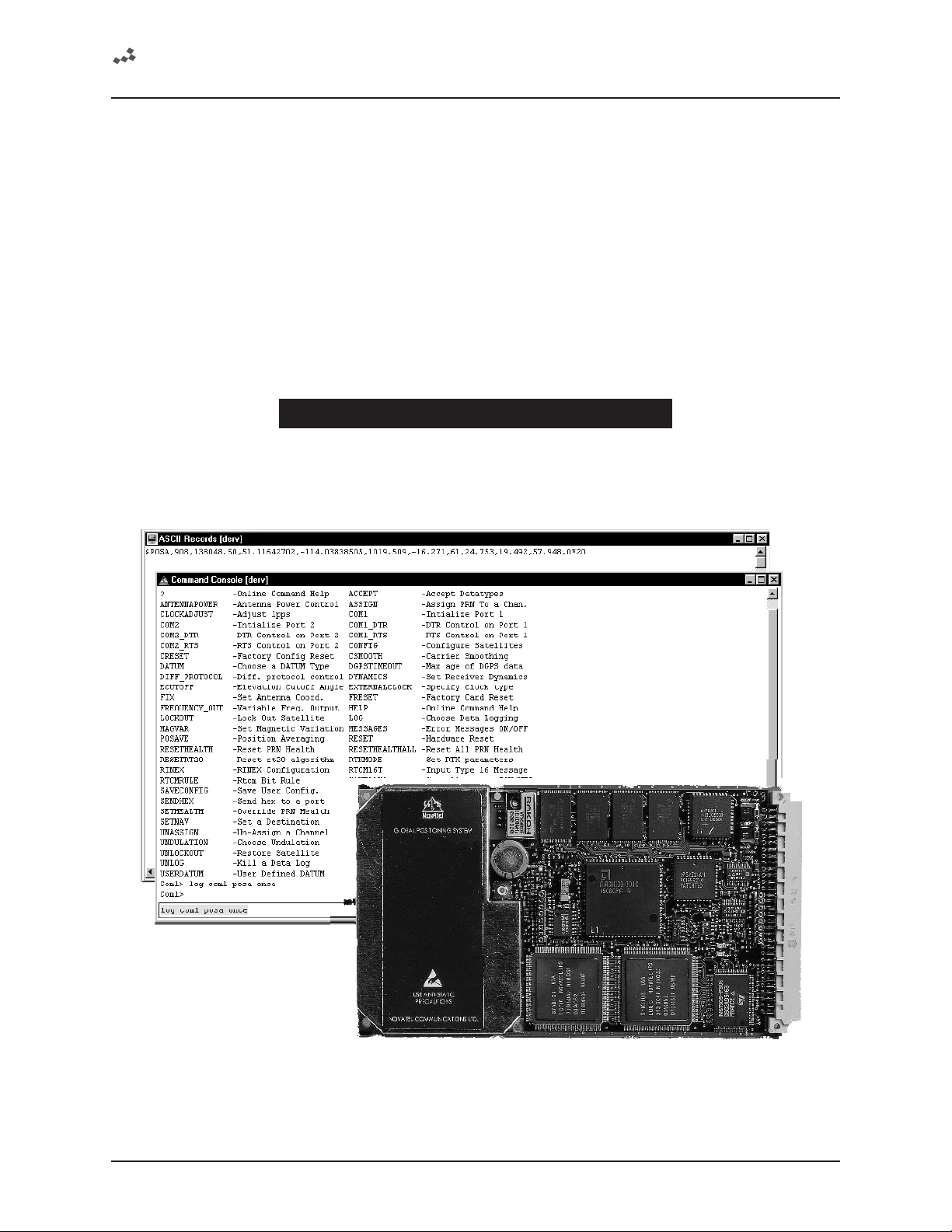
Graphical In te r fa c e
If your GPSCard comes with a disk containing NovAtel’s graphical interface software GPSolution, a Microsoft
Windows-based program, then you will be able to use your GPSCard with out struggling with communications
protocol or writing make-do software.
The View menu options allow you to select or de-select various visual aids and display screens. Take a look at all
of the options and keep o pen those you wish to display . To sen d commands and log data the Command C onsole
screen should be visible. ASCII format logs can be monitored on the ASCII Record screen.
MiLLennium Command Descriptions Manual 1
Page 8

1 Quick Start
e.g. On the command line of the Command Console screen type:log com1 posa once
After you hit the <Enter> key the ASCII Record screen will display the outpu t for your current position . See the
POSA/B log description in Appendix D.
1.2 DATA LOGGING
The GPSCard has four major l ogg ing formats:
• NovAtel Format Data Logs (ASCII/Binary)
NMEA Standard Format Data Logs (ASCII)
•
RTCM Standard Format Data Logs (Binary)
•
RTCA Standard Format Data Logs (Binary)
•
All data types can be logged using several methods of triggering each log event. Each log is initiated using the
command. The LOG command and syntax are listed on the following page.
LOG
Syntax:
Syntax Description Example
LOG LOG
port COM1 or COM2 Defaults to the port that the command was entered on. COM1
datatype Enter one of the valid ASCII or Binary Data Logs (see Chapter 4 and Appendix D) POSA
trigger Enter one of the following triggers. ONTIME
period Use only with the
offset Use only with the
hold Will prevent a log from being removed when the UNLOGALL command is issued HOLD
log [port],datatype,[trigger],[period],[offset],{hold}
ONCE Immediately logs the selected data to the selected port once. Default if trigger field is left
blank.
ONMARK Logs the selected data when a MARKIN electrical event is detected. Outputs internal buffers
ONNEW Logs the selected data each time the data is new even if the data is unchanged.
ONCHANGED Logs the selected data only when the data has changed.
ONTIME
[period], [offset]
CONTINUOUSLY Will log the data all the time. The GPSCard will generate a new log when the output buffer
from 0.05 second to 3600 seconds. Selected data is logged immediately and then periodic logging of the data will
start at the next even multiple of the period. If a period of 0.20 sec is chosen, then data will be logged when the
receiver time is at the 0.20, 0.40, 0.60 and the next (0.80) second marks. If the period is 15 seconds, then the
logger will log the data when the receiver time is at even 1/4 minute marks. The same rule applies even if the
chosen period is not divisible into its next second or minute marks. If a period of 7 seconds is chosen, then the
logger will log at the multiples of 7 seconds less than 60, that is, 7, 14, 21, 28, 35, 42, 49, 56 and every 7 seconds
thereafter.
logging events from the above startup rule. If you wished to log data at 1 second after every minute you would set
the period to 60 seconds and the offset to 1 second (Default is 0).
at time of mark - does not extrapolate to mark time. Use MKBA/B for extrapolated position
at time of mark.
Immediately logs the selected data and then periodically logs the selected data at a
frequency determined by the period and offset parameters. The logging will continue until
an UNLOG command pertaining to the selected data item is received (see UNLOG
Command).
associated with the chosen port becomes empty. The continuously option was designed for
use with differential corrections over low bit rate data links. This will provide optimal record
generation rates. The next record will not be generated until the last byte of the previous
record is loaded into the output buffer of the UART.
ONTIME
ONTIME
trigger. Units for this parameter are seconds. The selected period may be any value
trigger. Units for this parameter are seconds. It provides the ability to offset the
60
1
The syntax for a command can contain optional parameters (OPT1, OPT2, ...). OPT2 may only be used if it
is preceded by OPT1. OPT3 may only be used if it is preceded by OPT2 and so on. Parameters after and
including OPT1 will be surrounded by square brackets.
An optional parameter such as {hold} surrounded by braces may be used with the log without any preceding
optional parameters. Example:
log com1 posa 60 1 hold
log com1 posa hold
2 MiLLennium Command Descriptions Manual
Page 9

1 Quick Start
Example:
log com1,posa,ontime,60,1
If the
LOG syntax does not include a trigger type, it will be out put only once following execution of the LOG
command. If trigger type is specified in the LOG syntax, the log will continue to be output bas ed on the trigger
specification. Specific logs can be disabled using the
by using the
configuration status log (
UNLOGALL command (see Chapter 2 and Appendix C). All activated logs will be listed in the receiver
RCCA).
UNLOG command, whereas all enabled logs will be disabled
The [port] parameter is optional. If [port] is not specified, [port] is defaulted to the p ort that the command was
received on.
COMMONLY USED LOGS
Type Logs Trigger
Positioning PRTKA/B
POSA/B
Post Processing RGEA/B/D
REPA/B, ALMA/B
NMEA Position GPGLL
GPGGA
Other useful logs are
ontime or onmark
ontime
onchanged
ontime or onmark
• RCCA to list the default command settings
• ETSA to monitor the channel tracking status
• SATA to observe the satellite specific data
• DOPA to monitor the dilution of precision of the current satellite constellation
• RVSA to monitor the receiver status
For further information on output logging see Chapter 4 and the individual logs listed alpha betically in Appendix
D.
Use the
HELP command to list all available commands. For more information on sending commands see Chapter
2 and the individual commands listed alphabetically in Appendix C.
1.3 DIFFERENTIAL OPERATION
GPSCard receivers are capable of operating as either a reference station or a rover station. This makes the
MiLLennium GPSCard ideal for design into DGPS systems.
The GPSCard is capable of utilizing various formats of differential corrections. These formats are divided into two
primary groups
For detailed data structure concerning these logs, please see Chapters 4, 5, 6 and Appendix D.
Establish a Da ta Link
Operating the GPSCard with a DGPS system requires that the reference station b roadcast differential correction
data messages to one or more rover receivers. As there are many methods by which this can be achieved, it is up
to you to establish an appropriate data link that best suits your user requirements.
RTCM and RTCA.
Whatever data link is chosen, the operator of the reference station will want to ensure that the bit rate of data
transmission is suitable for the anticipated data li nk and remote users. Us e the GPSCard COMn c ommand to the
COM port default bit rate (default is 9600 bps, no parity, 8 data bits, 1 stop bit, no handshake, echo off).
Note that the GPSCard COMn_DTR and COMn_RTS commands are available for remote device keying (such as
a radio transmitter). These commands allow for flexible control of the DTR and RTS lines to be precisely t ime d
with log transmissions.
MiLLennium Command Descriptions Manual 3
Page 10

1 Quick Start
Further information may be found in Appendix A.
Table 1-1, following, is a GPSCard pseudorange differential initialization summary.
Table 1-1 GPSCard Pseudorange Differential Initialization Summary
REFERENCE
MONITOR STATION REMO TE ST ATION
MONITOR STATION REMOTE STATION
equired: Required:
Required: Required:
FIX POSITION lat lon h g t id (h e a lth ) ACCEPT port
FIX POSITION lat lon h g t id (h e a lth ) ACCEPT port
LOG port
LOG port
DATATYPE
ecommended Options: Recommended Options:
Recommended Options: Recommended Options:
LOG DATATYPES
LOG DATATYPES
DATATYPE
(binary):
(binary):
ontime 5
ontime 5
RTCMB
RTCMB
RTCAB
RTCAB
RTCM
RTCM
RTCA
RTCA
ACCEPT DATATYPES
ACCEPT DATATYPES
DATATYPE
DATATYPE
(binary):
(binary):
RTCM
RTCA
RTCM
RTCA
(ascii):
LOG DATATYPES
LOG DATATYPES
elated Commands /Logs: Related Commands /Logs:
Related Commands /Logs: Related Commands /Logs:
RTCMRULE RTCMRULE
RTCMRULE RTCMRULE
DATUM DATUM
DATUM DATUM
xample 1:
Example 1:
xample 2:
Example 2:
OTES: Italicized entries indicate user definable.
NOTES: Italicized entries indicate user definable.
fix position 51.3455323 -114.2895345 1201.123 555 0
fix position 51.3455323 -114.2895345 1201.123 555 0
log com1 RTCM ontime 2
log com1 RTCM ontime 2
fix position 51.3455323 -114.2895345 1201.123 555
fix position 51.3455323 -114.2895345 1201.123 555
log com2 rtcaa ontime 2
log com2 rtcaa ontime 2
(ascii):
RTCMA
RTCMA
RTCAA
RTCAA
Example 1:
Example 1:
Example 2:
Example 2:
ACCEPT COMMANDS
ACCEPT COMMANDS
POSA/B
POSA/B
VLHA/B
VLHA/B
CDSA/B
CDSA/B
GPGGA
GPGGA
accept com 2 rtcm
accept com 2 rtcm
log com1 posa ontime 1
log com1 posa ontime 1
accept com2 commands
accept com2 commands
log com1 posa ontime 0.2
log com1 posa ontime 0.2
log com1 vlha ontime 0.2
log com1 vlha ontime 0.2
(ascii):
(ascii):
RTCMA
RTCAA
RTCMA
RTCAA
Initialization - Re ference Station
Differential mode of operation is established at the ref erence station through a two ste p process: fix position and
logging observation and correction data.
FIX POSITION
The reference station must initialize the precise position of its reference antenna phase centre (lat/lon/hgt). This is
accomplished by utilizing the GPSCard
FIX POSITION command. The syntax is as follows:
Syntax:
FIX POSITION lat lon height station id health
Example:
fix position 51.3455323,-114.2895345,1201.123,555,0
4 MiLLennium Command Descriptions Manual
Page 11

1 Quick Start
NOTES: Entry of the station ID and health are optional
The accuracy of the reference station’s
FIX POSITION setting will directly affect the accuracy of its computed
differential corrections. Good results at the rover station are dependent on the reference station’s combined
position errors being kept to a minimum (e.g., fix position error + multipath errors).
The GPSCard performs all computations based on WGS84 and is defaulted as such, regardless of
DATUM
command setting. The datum in which you choose to operate is converted from WGS84; therefore, all
differential corrections are based on WGS84. Ensure that any change in your operating datum is set prior
to
FIX POSITION.
When transmitting RTCM type data, the GPSCard has various options for assigning the number of data
bits per byte. Please see the GPSCard command
RTCMRULE, Appendix C for further information concerning
RTCM data bit rule settings.
The FIX POSITION “health” field entered will be reported in word 2 of the RTCM message frame header.
Once the GPSCard has its position data fixed and is trackin g three or more satellites, it is now ready to transmit
differential correction and observation data to the rover stations.
LOG BROADCAST DATA
Assuming that a data link has been established, use the GPSCard log command to send observation and differential
corrections data for broadcast to the rover stations.
Syntax:
LOG port data ontime seconds
Example:
log com1 rtcm ontime 5
REMINDER: Ensure that the bit rate of the data link is suitable for the differential type, logging rate and
maximum message length of the data type being logged.
1.4 RTK MODE
Currently, NovAtel’s RTK system uses proprietary messaging. Consequently, both the reference station and
remote station must use NovAtel GPS receivers in order for the system to work and perform as described.
Data Communications Link
It is the user’s responsibility to provide a data commu nications link between the reference station and remote
station. The data transfer rate must be high enough to ensure that sufficient reference station messages reach the
remote station to keep extrapolation errors from growing too large; see Table 1-2 .
Table 1-2 Latency-Induced Extrapolation Error
Time since last reference station observation Typical extrapolation error (CEP)
0-2 seconds 1 cm/sec
2-7 seconds 2 cm/sec
7-30 seconds 5 cm/sec
Generally, a communications link capable of data throughput at a rate of 4800 bits per second or higher is
sufficient. However, it is possible to satisfactorily use a lower rate; see Chapter 6, Message Formats for additio nal
information. The minimum data transfer rate is based on the following:
1. RT-2 requires that the reference station periodically transmit two RTCA Standard Type 7 messages:
MiLLennium Command Descriptions Manual 5
Page 12

1 Quick Start
• An RTCAOBS message contains reference station satellite observation information, and
should be sent once every 1 or 2 seconds.
• An RTCAREF message contains reference station position information, and should be
sent once every 10 seconds.
2. RT-20 requires that the reference station periodically transmit either the RTCA messag es listed above (the
recommended option), or the RTCM SC-104 Type 3 & 59N messages:
• A Type 3 message contains reference station position information, and should be sent
once every 10 seconds (although it is possible to send it as infrequently as once every 30
seconds).
• A Type 59N message contains reference station satellite observation information, and
should be sent once every 2 seconds.
Further information on RTCA and RTCM message formats is contained in Chapter 6.
System Initialization
The RTK system is designed for ease of use: you set up the remote station, enter a command so that it accepts RT2 or RT-20 messages from the reference stati on, and are ready to go. There are options, however, which can be
used to adapt the system to a specific application. S ome options a pply only to the reference st ation, while oth e rs
apply only to the remote station. Detailed descriptions can be found in Appendix C, Commands Summary.
In the following sections, keep the following in mind:
• Dynamics modes. For reliable performance the antenna should not move more than 1-2
cm when in static mode. See the
more information.
• When using the
sea level; it will be converted to ellipsoidal height inside the receiver. You can enter an
undulation value, if desired, using the
receiver estimates an undulation with its internal table. The format of the optional station
ID field depends on whether RTCM or RTCA messages are being used: if RTCM, any
number from 0 - 1023 is valid, while if RTCA, any 4-character string of numbers and
upper-case letters, enclosed in quotation marks, is valid. See Appendix C for additional
information on the station id field.
• The COMn field refers to the serial port (either COM1 or COM2) to which data
communications equipment is connected. The serial port assignment at the reference and
remote stations need not be the same; e.g. a radio transmitter might be connected to
COM1 at the reference station, and a radio receiver to COM2 at the remote station.
FIX POSITION command, the height entered must be in metres above mean
RTKMODE commands in Chapter 2 and Appendix C for
UNDULATION command; if none is entered, the
INITIALIZATION FOR RTCA-FORMAT MESSAGING (RT-2 OR RT-20)
The following commands will enable RTCA-format messaging and allow RT-2 or RT-20 to operate with the
remote station either at rest or in motion. Note that the optional station health field in the existing FIX POSITION
command is not currently implemented in NovAtel’s RTCA messages, though it will be in the future.
1. At the reference station:
fix position lat,lon,height,
station id
log comn,rtcaref,ontime,interval
log com
Example:
fix position 51.11358042,-114.04358013,1059.4105,”RW34”
n
,rtcaobs,ontime,interval
6 MiLLennium Command Descriptions Manual
Page 13

1 Quick Start
log com1,rtcaref,ontime,10
log com1,rtcaobs,ontime,2
2. At the remote station:
accept comn,rtca
Example:
accept com2,rtca
Congratulations! Your RTK system is now in operation!
INITIALIZATION FOR RTCM-FORMAT MESSAGING (RT-20 ONLY)
Although RT-20 can operate with either RTC A or RTCM-format messaging, the use of RT CA-format messages is
recommended (see Chapter 6 for further information on this topic). Nev ertheless, the follow ing commands will
enable RTCM-format messaging and allow RT-20 to operate with the remote station either at rest or in motion:
1. At the reference station:
fix position lat,lon,height,
log comn,rtcm3,ontime,interval
station id,station health
log com
Example:
fix position 51.11358042,-114.04358013,1059.4105,119,0
log com1,rtcm3,ontime,10
log com1,rtcm59,ontime,2
n
,rtcm59,ontime,interval
2. At the remote station:
accept comn,rtcm
Example:
accept com2,rtcm
Congratulations! Your RT-20 system is now in operation!
Monitoring Your RTK Output Data
At the remote station, you could now select any or all of these output logs for positioning information:
• BSLA/B Baseline Measurement
• NMEA-format logs
• POSA/B Computed Position
• PRTKA/B Best Position
• RPSA/B Reference Station Position & Health
• RTKOA/B RTK Output - Time Matched Positions
The POSA/B, PRTKA/B and NMEA-format logs contain t he low-latency position; the RTKA/B logs contai n t he
matched position. The low-latency solution is the recommended one for kinematic users, while the matched
solution is the one recommended for stationary users. For a discussion on low-latency and matched positions, see
the Differential Positioning section of Appendix A.
Options for Loggi ng Differential Corrections
SET DGPSTIMEOUT
The DGPSTIMEOUT command allows the reference station to set the delay by which it will inhibit utilization of new
ephemeris data in its differential corrections. This delay ensures that the remote receivers have had sufficient time
MiLLennium Command Descriptions Manual 7
Page 14

1 Quick Start
to collect updated ephemeris data as well.
A delay of 120 to 130 seconds will typically ensure that the rover stations have collected updated ephemeris. After
the delay period is passed, the reference station will begin using new ephemeris data. To enter an ephemeris delay
value, you must first enter a numeric placeholder in the DGPS delay field (e.g., 2). When operating as a reference
station, DGPS delay will be ignored (see the
DGPSTIMEOUT command found in Chapter 2 and Appendix C for
further information on using this command at rover stations.)
Syntax:
DGPSTIMEOUT dgps delay ephem delay
Command Option Description Default
DGPSTIMEOUT Command
dgps delay min. 2
max. 1000
ephem delay min. 0
max. 600
Maximum age in seconds 60
Minimum time delay in seconds 120
Example:
dgpstimeout 2,300
USING RTCM SC-104 LOG TYPES
RTCM SC-104 is a standard for transmitting differential corrections between equipment from different
manufacturers. The NovAtel GPSCard is capable of transmitting or receiving
To facilitate transmitting the
RTCM data over shared data links, the GPSCard is also capable of sending the RTCM
RTCM data.
log in NovAtel ASCII format (RTCMA) or with the NovAtel Binary Header (RTCMB) added to allow
synchronous transmission and reception along with other data types.
REMEMBER: When sending or receiving RTCM log types, it is important to ensure that all connected
equipment are using the same RTCMRULE for compatibility.
The easiest method to send RTCM Standard logs is from the COM1 or COM2 ports of the reference GPSCard. The
easiest method to receive the RTCM data is through the COM1 or CO M2 port of the rover GPSCard. The rover
GPSCard must issue the “ACCEPT port RTCM” command to dedicate a port before it will accept the
RTCM data
into that port.
The
RTCMA log can be intermixed with other NovAtel ASCII data over a common communication port. It will be
directly interpreted by a rover GPSCard as a Special Data Input Command ($RTCM). “ACCEPT port
COMMANDS” must be used with this input command. A non-NovAtel rover station will need to strip off the
header ($RTCM) and terminator (*xx), then convert the hexadecim al data to binary before the R TCM Standard
data can be retrieved.
The
RTCMB log can be intermixed with other NovAtel Binary data over a common communication port.
REMEMBER: Use the CDSA/B logs to monitor the COM port activity, success, and decoding errors.
USING RTCA LOG TYPES
The RTCA (Radio Technical Commission for Aviation Services) Standard is being designed to support
Differential Global Navigation Satellite System (DGNSS) Special Category 1 (SCAT-I) precision approaches. The
perceived advantage to using
using
RTCM type messages is that RTCM transmits 30-bit words, and the data is difficult to decode and process
because of the parity algorithm and regular word sizes used.
8 MiLLennium Command Descriptions Manual
RTCA type messages for transmitting and receiving differential corrections versus
RTCA is transmitted in 8-bit words, which are easier
Page 15

1 Quick Start
to generate, process and decode. The RTCA messages are therefore smaller, they have a 24 bit CRC that is much
more robust than
RTCM messages, and they permit the use of a four-alpha-character station ID.
RTCA Standard logs can be received through the COM1 or COM2 port of the rover GPSCard. The remote
GPSCard must issue the “ACCEPT port RTCA” command to dedicate a port before it will accept the
input to that port. The
RTCA logs cannot be intermixed with other logs.
RTCA data
The RTCAA log can be intermixed with other NovAtel ASCII data over a common communicat ions port. It will
be directly interpreted by a rover GPSCard as a Special Data Input Command ($RTCA). “ACCEPT port
commands” must be used with this input command. A non-NovAtel rover station will need to strip off the header
($RTCA) and terminator (*xx), then conv ert the hexadecimal data to binary before the RTCA Standard can be
retrieved.
The RTCAB log can be intermixed with other NovAtel binary data. The C OM1 or COM2 port of the remote
GPSCard must be dedicated to receiving
issued. The remote GPSCard identifies the
and will interpret only the
RTCA data portion of the log.
RTCA data only, and so the “ACCEPT port RTCA” command must be
RTCAB log by the message block identifier contain ed in the message,
NOTE: The CDSA/B logs may be used to monitor the COM port activity and differential data decode success.
Initialization - Rover Station
It is necessary to ini tialize t he rover receiv e r to accept o bservation dat a from th e referen ce st ation. If th e receiv e r
is not correctly initialized, it will proceed to compute solutions in single point positioning mode.
Before initializing, ensure that the data link with the reference station has been properl y set up. As well, ensure that
the COM port which is to receive the differential data is s et up to match the bit rate an d protocol settings of the
reference station broadcast data.
Establishing differential mode of operation at the rover receiver is primarily a one-step process whereby the accept
command is used to enable reception of observation data from the reference station.
ACCEPT COMMAND
The accept command is primarily used to set the GPSCard’s COM port command interpreter for acceptance of
various data formats. (see the
ACCEPT command in Chapter 2 and Appendix C)
Syntax
ACCEPT port mode
Example:
accept com2 rtcm
Once intitialized, the rover GPSCard receiver will operate in single point mode until the differential messages are
received. If the data messages are lost, the G PSCard will revert to single point positioning until the pseu dorange
correction messages are restored.
NOTES: Ensure that the GPSCard RTCMRULE settings agree with the bit rule being transmitted by the RTCM
reference station. Unless otherwise set, all GPSCards default to 6CR.
LOG POSITION DATA AND OTHER USEFUL DATA
The GPSCard remote receiver has many options for information data logging. To monitor position status, the user
may find the
velocity data can be found in the
PRTKA/B logs to be the most informative. Oth er options exist, such as POSA/B and GPGGA. As well,
VLHA/B, SPHA/B and GPVTG logs. It is really up to the user’s specific applications
as to the full range of logs required by the user.
MiLLennium Command Descriptions Manual 9
Page 16

2 Command Descriptions
2 COMMAND DESCRIPTIONS
2 COMMAND DESCRIPTIONS
2.1 GENERAL
This section describes all commands accepted by the GPSCard with the exception of the "Special Data Input
Commands". They are listed in alphabetical order. For descriptions of output logs using the
Chapter 4.
The GPSCard is capable of responding to over 50 differ ent input co mmands. You will fi nd t hat once you be c o me
familiar with these commands, the GPSCard offers a wide range in operational flexibility. All com mands are
accepted through the
COM1 and COM2 serial ports. See Table 2-1 for a complete command listing.
NOTE: You will find the HELP command a useful tool for inquiring about the various commands available.
The following rules apply when entering commands from a terminal keyboard:
LOG command, see
• The commands are not case sensitive (
e.g.
e.g.
HELP or help
FIX POSITION or fix position
COMMAND or command).
• All commands and required entries can be separated by a space or a comma
(command,variable
OR command variable).
e.g. datum,tokyo
e.g. datum tokyo
e.g. fix,position,51.3455323,-117.289534,1002
e.g. fix position 51.3455323 -117.289534 1002
e.g. com1,9600,n,8,1,n,off
e.g. com1 9600 n 8 1 n off
e.g. log,com1,posa,onchanged
e.g. log com1 posa unchanged
• At the end of a command or command string, press the <CR> key. A carriage return is what
the card is looking for and is usually the same as pressing the <Enter> key.
• Most command entries do not provide a response to the entered command. Exceptions to
this statement are the
VERSION and HELP commands. Otherwise, successful entry of a
command is verified by receipt of the COM port prompt (i.e. COM1> or COM2>).
The syntax for a command can contain optional parameters (OPT1, OPT2, ...). OPT2 may only be used if it
is preceded by OPT1. OPT3 may only be used if it is preceded by OPT2 and so on. Parameters after and
including OPT1 will be surrounded by square brackets.
An optional parameter such as {hold} surrounded by braces may be used with the log without any preceding
optional parameters
Example:
log com1 posa 60 1 hold
log com1 posa hold
10 MiLLennium Command Descriptions Manua l
Page 17

2 Command Descriptions
2.2 COMMAND TABLES
Table 2-1 lists the commands by function while Table 2-2 is an alphabetical listing of commands. Please see
Appendix C for a more detailed description of individual commands which are listed alphabetically.
Table 2-1 Commands By Function Table
COMMUNICATIONS, CONTROL AND STATUS
Commands Descriptions
ANTENNAPOWER Power to the low-noise amplifier of an active antenna
COMn COMn port configuration control
COMn_DTR DTR handshaking control
COMn_RTS RTS handshaking control
DIFF_PROTOCOL ➀ Differential Protocol Control
FREQUENCY_OUT Variable frequency output (programmable)
LOG Logging control
MESSAGES Disable error reporting from command interpreter
RINEX Configure the user defined fields in the file header
RTCMRULE Sets up RTCM bit rule
RTCM16T Enters an ASCII message
SEND Sends ASCII message to COM port
SENDHEX Sends non-printable characters
SETL1OFFSET ➀
Add an offset to the L1 pseudorange to compensate for
signa l delays
GENERAL RECEIVER CONTROL AND STATUS
Commands Descriptions
$ALMA Download almanac data file
CRESET R eset receiver to factory default
DYNAMICS Set correlator tracking bandwidth
HELP On-line command help
RESET Performs a hardware reset (OEM only)
SAVEALMA Saves the latest almanac in NVM
SAVECONFIG Saves current configuration (OEM only)
$TM1A Injects receiver time of 1 PPS
VERSION Software/hardware information
POSITION, PARAMETERS, AND SOLUTION FILTERING CONTROL
Commands Descriptions
CSMOOTH ➀ Sets amount of carrier smoothing
DATUM Choose a DATUM name type
ECUTOFF Satellite elevation cut-off for solutions
FIX HEIGHT Constrains to fixed height (2D mode)
FIX POSITION Constrains to fixed lat, lon, height
FRESET Clears all data which is stored in NVM
$IONA Download ionospheric correction data
LOCKOUT Deweights a sate llite in solutions
$PVAA ➀ Position, velocity and acceleration in ECEF coordinates
RTKMODE Setup the RTK mode
UNDULATION Ellipsoid-geoid separation
USERDATUM User-customized datum
➀ Intended for advanced users of GPS only.
MiLLennium Command Descriptions Manual 11
Page 18

2 Command Descriptions
Table 2-1 Commands By Function Table (continued)
SATELLITE TRACKING AND CHANNEL CONTROL
Commands Descriptions
$ALMA Download almanac data file
ASSIGN Satellite channel assignment
CONFIG Switches the channel configuration of the GPSCard
DYNAMICS Sets correlator tracking bandwidth
FIX VELOCITY Aids high velocity reacquisition
RESETHEALTH R eset PRN health
SETHEALTH Overrides broadcast satellite health
WAYPOINT NAVIGATION
Commands Descriptions
MAGVAR Magne tic variation co rrection
SETNAV Waypoint input
DIFFERENTIAL REFERENCE STATION
Commands Descriptions
DGPSTIMEOUT Sets ephemeris delay
FIX POSITION Constrain to fixed (reference)
LOG Selects required di fferential-output log
POSAVE Implements position averaging for reference station
RTCMRULE Selects RTCM bit rule
SETDGPSID Set reference station ID
DIFFERENTIAL REMOTE STATION
Commands Descriptions
ACCEPT Accepts RTCM1, RTCA or RTCAB differential inputs
$ALMA Input almanac data
DGPSTIMEOUT Set maximum age of differential data accepted
RESET Performs a hardware reset
$RTCA RTCA differential correction input (ASCII)
$RTCM RTCM differential correction in put (ASCII)
RTCMRULE Selects RTCM bit rule
SETDGPSID Select differential reference station ID to receive
POST PROCESSING DATA
Commands Descriptions
Depends on operating platform
CLOCK INFORMATION, STATUS, AND TIME
Commands Descriptions
CLOCKADJUST Enable clock modelling & 1PPS adjust
DIFF_PROTOCOL ➀ Differential protocol control
EXTERNALCLOCK Sets default parameters of an optional external oscillator
EXTERNALCLOCK FREQUENCY Sets clock rate
SETTIMESYNC ➀ Enable or disable time synchronization
$UTCA Download UTC data
➀ Intended for advanced users of GPS only
12 MiLLennium Command Descriptions Manua l
Page 19

2 Command Descriptions
Table 2-2 GPSCard Command Summary
Command Description Syntax
$ALMA Injects almanac (follows NovAtel ASCII log format)
$IONA Injects ionospheric refraction corrections (follows NovAtel ASCII log format)
$PVAA Injects latest computed position, velocity and acceleration (follows NovAtel ASCII log format)
$REPA Injects raw GPS ephemeris data (follows NovAtel ASCII log format)
$RTCA Injects RTCA format DGPS corrections in ASCII (Type 1) (follows NovAtel ASCII log format)
$RTCM Injects RTCM format differential corrections in ASCII (Type 1) (follows NovAtel ASCII log format)
$TM1A Injects receiver time of 1 PPS (follows NovAtel ASCII log format)
$UTCA Injects UTC information (follows NovAtel ASCII log format)
ACCEPT Port input control (set command interpreter) accept port,option
ANTENNAPOWER Power to the low-noise amplifier of an active antenna antennapower flag
ASSIGN Assign a prn to a channel # assign channel,prn,doppler, search window
UNASSIGN Un-assign a channel unassign channel
UNASSIGNALL Un-assign all channels unassignall
CLOCKADJUST Disable clock steering mechanism clockadjust switch
COMn Initialize Serial Port (1 or 2) comn bps,parity,databits,stopbits,
handshake,echo
COMn_DTR Programmable DTR lead/tail time comn_dtr control,active,lead,tail
COMn_RTS Programmable RTS lead/tail time comn_rts control,active,lead,tail
CONFIG Switches the channel configuration of the GPSCard config cfgtype
CRESET Configuration reset to factory default creset
CSMOOTH Sets carrier smoothing csmooth value
DATUM Choose a DATUM name type datum option
USERDATUM User defined DATUM userdatum semi-major,flattening,dx,dy,dz,
DGPSTIMEOUT Sets maximum age of differential data to be accepted and
ephemeris delay
DIFF_PROTOCOL Differential correction message encoding and decoding for
DYNAMICS Set receiver dynamics dynamics option [user_dynamics]
ECUTOFF Set elevation cutoff angle ecutoff angle
EXTERNALCLOCK Sets default parameters of an optional external oscillator externalclock option
EXTERNALCLOCK
FREQUENCY
FIX HEIGHT Sets height for 2D navigation fix height height [auto]
FIX POSITION Set antenna coordinates for reference station fix position lat,lon,height [station id] [health]
FIX VELOCITY Accepts INS xyz (ECEF) input to aid in high velocity
UNFIX Remove all receiver FIX constraints unfix
FREQUENCY_OUT Variable frequency output (programmable) frequency_out n,k
FRESET Clears all data which is stored in non-volatile memory freset
HELP or ? On-line command help help option or ? option
LOCKOUT Lock out satellite lockout prn
UNLOCKOUT Restore satellite unlockout prn
UNLOCKOUTALL Restore all satellites unlockoutall
LOG Choose data logging type log [port],datatype,[trigger],[period],[offset],{hold}
UNLOG Disable a data log unlog [port],data type
UNLOGALL Disable all data logs unlogall [port]
implementation in the GPS card firmware
Sets clock rate external frequency clock rate
reacquisition of SVs
rx,ry,rz, scale
dgpstimeout value value
diff_protocol type key
or diff_protocol disable
or diff_protocol
fix velocity vx,vy,vz
MiLLennium Command Descriptions Manual 13
Page 20

2 Command Descriptions
Table 2-2 GPSCard Command Summary (continued)
MAGVAR Set magnetic variation correction magvar value
MESSAGES Disable error reporting from command interpreter messages port,option
POSAVE Implements position averaging for reference station posave maxtime, maxhorstd, maxverstd
RESET Performs a hardware reset (OEM only) reset
RINEX Configure the user defined fields in the file headers rinex cfgtype
RTCM16T Enter an ASCII text message to be sent out in the RTCM data
RTCMRULE Set variations of the RTCM bit rule rtcmrule rule
RTKMODE Set up the RTK mode rrtkmode argument, data range
SAVEALMA Save the latest almanac in non-volatile memory savealma option
SAVECONFIG Save current configuration in non-volatile memory (OEM
SEND Send an ASCII message to any of the communications ports send port ascii-message
SENDHEX Sends non-printable characters in hexadecimal pairs sendhex port data
SETDGPSID Enter in a reference station ID setdgpsid option
SETHEALTH Override PRN health sethealth prn,health
RESETHEALTH Reset PRN health resethealth prn
RESETHEALTHALL Reset all PRN health resethealthall
SETL1OFFSET Add an offset to the L1 pseudorange to compensate for signal
SETNAV Set a destination waypoint setnav from lat,from lon,to lat, to lon,track offset,
SETTIMESYNC Enable or disable time synchronization settimesync flag
UNDULATION Choose undulation undulation separation
VERSION Current software and hardware information version
Range Value Default
stream
only)
delays
rtcm16t ascii message
saveconfig
setL1offset distance
from port,to port
14 MiLLennium Command Descriptions Manua l
Page 21

2 Command Descriptions
When the GPSCard is first powered up, or after a FRESET command, all commands will revert to the factory default
settings. An example is shown below . The
Use the
RCCA log to reference station command and log settings.
SAVECONFIG command can be used to modify the power-on defaults.
Note: All previously stored configurations that were saved to non-volatile memory are erased (including Saved
Config, Saved Almanac, and Channel Config).
Example:
$RCCA,COM1,9600,N,8,1,N,OFF,ON*2B
$RCCA,COM1_DTR,HIGH*70
$RCCA,COM1_RTS,HIGH*67
$RCCA,ACCEPT,COMl,COMMANDS*5F
$RCCA,COM2,9600,N,8,1,W,OFF,ON*28
$RCCA,COM2_DTR,HIGH*73
$RCCA,COM2_RTS,HIGH*64
$RCCA,ACCEPT,COM2,COMMANDS*58
$RCCA,UNDULATION,TABLE*56
$RCCA,DATUM,WGS84*15
$RCCA,USERDATUM,6378137.000,298.257223563,0.000,0.000,0.000,0.000,0.000,0.000,0.000*6A
$RCCA,SETNAV,DISABLE*51
$RCCA,MAGVAR,0.000*33
$RCCA,DYNAMICS,HIGH,AIR*6D
$RCCA,UNASSIGNALL*64
$RCCA,UNLOCKOUTALL*20
$RCCA,RESETHEALTHALL*37
$RCCA,UNFIX*73
$RCCA,ANTENNAPOWER ON*1E
$RCCA,SETDGPSID,ALL*10
$RCCA,RTCMRULE,6CR*32
$RCCA,RTCM16T*48
$RCCA,CSMOOTH,20.00*7E
$RCCA,ECUTOFF,0.00*45
$RCCA,FREQUENCY_OUT,DISlBLE*l2
$RCCA,EXIERRALCLOCK,DISABLE*12
$RCCA,CLOCKADJUST,ENABLE*47
$RCCA,SETTIMESYNC,DISABLE*17
$RCCA,SETL10FFSET, 0. 000000*3F
$RCCA,MESSAGES,ALL,ON*67
$RCCA,DGPSTIlMEOUT,60.00,120.00*51
$RCCA,SAVEALMA,ONNEW*4E
$RCCA,POSAVE,DISABLE*59
$RCCA,CONFIG,STANDARD*02
$RCCA,DIFF_PROTOCOL,DISABLED*47
MiLLennium Command Descriptions Manual 15
Page 22

2 Command Descriptions
All Commands: Optional calculation of the checksum
When an input command is followed by an optional checksum, the checksum will be verified before the command
is executed. The checksum is the resu lt of th e logical exclusive- OR o peration on al l the bits in the mes sage. So,
the checksum of a command with parameters will change if the parameters are modified.
NOTE: The command must be typed in uppercase for the proper checksum to be calculated.
As an example, it may be essential to ensure that a receiver has received and executed the correct command from
a host computer. If the checksum were calculated by the sender and attached to the command, the receiver would
be able to recognize if errors had been introduced and if so, alert the sender to this with an “Invalid Command
CRC” message.
Example:
FIX HEIGHT 4.567[CR][LF]
FIX HEIGHT 4.567*66[CR][LF]
Both are acceptable, but only the second one would trigger the verification function.
All Commands : Re spons e to an invalid command inpu t
In an effort to be more descriptive, an invalid command entry now elicits “Invalid Command Name” rather than
“Invalid Command Option”.
16 MiLLennium Command Descriptions Manua l
Page 23

3 Special Data Input Commands
32SPECIAL DATA INPUT COMMANDS
3
SPECIAL DATA INPUT COMMANDS
These entries are data messages that are generated by one GPSCard and sent to another. For example, consider a
special configuration in which a GPSCard #1 is able to send these data messages to a GPSCard #2 via a serial port.
For GPSCard #1, this is no differen t than sending thes e data messages to a file or a screen. Each of these data
messages has a special header which is interpreted by GPSCard #2 to mean that the data in that message is to be
used as an update of its own GPS parameters such as time, position, velocity, acceleration or knowledge of satellite
ephemeri s.
In this general category also belong the RTCM data messages ($RTCM1A, $RTCM3A, $RTCM9A, $RTCM16A
and $RTCM59A). These are describe in further detail in Chapter 6, Message Formats.
The injection of special command data can take place via
COM1 or COM2. Remember, the source of these special
data commands are valid NovAtel ASCII data logs.
The special data commands fall into two categories: Almanac Data and Differential Corrections.
3.1 ALMANAC DATA
The GPSCard’s standard features include almanac data collection. Following a cold-start boot-up or system reset,
the GPSCard will begin a sky search. Once a valid satellite is acquired, the GPSCard will begin almanac
downloading and decoding. This process will take at least 12.5 minutes following the cold-start (assuming there
are no problems with satellite visibility or the antenna system). It is noted that Ionospheric C orrection Data and
UTC data are also collected at the same time as almanac data and will also be available following the 12.5 mi nutes
collection period mentioned above.
12 channel OEM cards with the
memory. They will also automatically load the last saved almanac following a cold start or a reset. The card will
save an almanac and ionospheric and
memory (NVM), or if the GPS week number of the received data is newer than the week number of the data in
NVM. The save will not occur unti l betw een 12. 5 and 25 mi nutes hav e elapsed since the last reset. To ch eck if
almanac data is saved in the NVM of the OEM card, check the "almanac data saved" bit in the receiver status word.
See the description of the
RCSA/B logs, Appendix D for details.
The GPSCard is capable of logging almanac data utilizing the NovAtel-format ASCII log command option
Once logged, the data records will precede the header with the $ character (e.g., $
There are no specific NovAtel log option commands to independently specify output of ionospheric or
parameters. These parameters will always output following the $ALMA log (identifiable by the headers $IONA and
$
UTCA respectively). See Chapter 4 and Appendix D for more information on the ALMA output log command
option.
SAVECONFIG option will automatically save almanacs in their non-volatile
UTC data received from a satellite if there is no cu rrent data in non -volatile
ALMA.
ALMA).
UTC
The GPSCard has the capability to accept injection of previously logged NovAtel-format ASCII almanac data
($
ALMA, $IONA, and $UTCA). The GPSCard will interpret this log data as special data input commands. This
provides the user with the advantage of being able to i nject recent almanac data following a cold-start or
RESET
without having to wait the 12.5 minutes described in above paragraphs. As well, this provides you with faster and
more accurate first-fix data because of the advan tage of a full almanac being resident immediately foll owing the
injection of the special data input commands described above. This is especially beneficial when the receiver is
cold-starting in an environment with poor reception and frequent satellite visibility obstruction.
There are various ways by which this can be accomplished.
• By connecting the
COM2 port of another GPSCard (remote). The reference card is assumed to be tracking
satellites for some time and can be commanded by the
COM1 or COM2 port from one GPSCard (reference) directly to the COM1 or
ALMA log command option to output
almanac records to the remote card. The remote card can be assumed to be just powered-up
RESET and will recognize the $ALMA, $IONA, and $UTCA data as special input commands
or
and update its almanac tables with this new data.
MiLLennium Command Descriptions Manual 17
Page 24

3 Special Data Input Commands
REMEMBER: When connecting two GPSCard COM ports together, the MESSAGES command option should be
set to "OFF" to prevent inter-card "chatter".
The MiLLennium GPSCard can log current almanac data to a PC connected to its
COM1 or COM2 port. Assuming
the PC is correctly c onfigured using terminal emulator comm unications software, then th e PC can redirect the
GPSCard almanac log to its disk storage device. At a later time following a system restart, the GPSCard can have
this almanac.dat file (containing $
ALMA, $IONA, and $UTCA records) immediately downloaded as a special input
command for immediate use. Refer to the MiLLEnnium GPSCard Guide to Installation and Operating manual for
more information a bout interfacing with the
OEM card with a PC. [Note: this procedure will generally not be
required with OEM cards as all 12 channel cards now have an almanac save feature bu ilt in using non-volatile
memory.]
$ALMA...
Use this special data input command to quickly update the GPSCard almanac tables following a system restart. It
is generated from a GPSCard
$ALMA,1,3.55148E-003,552960,744,-7.8174E-009,6.10457691E-002,-1.1820041E+000,
1.90436112E+000,-1.8119E-005,-3.6379E-012,1.45854758E-004,2.65602532E+007,
9.55600E-001,1,0,0*0C
...
(one record for each valid satellite)
...
$ALMA,31,4.90379E-003,552960,744,-7.9660E-009,-3.1044479E+000,6.13853346E-001,
1.92552900E+000,6.67572E-006,3.63797E-012,1.45861764E-004,2.65594027E+007,
9.61670E-001,1,0,0*3F
ALMA log and is accepted as the following format:
$IONA...
Use this special data input com mand to quickly update the GPSCa rd ionospheric corrections tables follow ing a
system restart (always appended to $
initial position solutions computed by the GPSCard are as accurate as possible. It is generated from a GPSCard
ALMA log and is accepted by any GPSCard as the following format:
ALMA records unless intentionally s tripped). This data will ensure that the
$IONA,1.0244548320770265E-008,1.4901161193847656E-008,-5.960464477539061E-008,
-1.192092895507812E-007,8.8064000000000017E+004,3.2768000000000010E+004, -
1.966080000000001E+005,-1.966080000000001E+005*02
18 MiLLennium Command Descriptions Manua l
Page 25

3 Special Data Input Commands
$UTCA...
Use this special data input command to quickly update the GPSCard Universal Time Coordinated (UTC) parameters
following a sy stem restart (always a ppended to $
required before the GPSCard can accurately compute
minutes after a reset for the GPSCard to receive current
GPSCard will null
NMEA log data fields until valid UTC parameters are collected or injected by the $UTCA input
command. This command is generated from a GPSCard
$UTCA,-1.769512891769409E-008,-1.776356839400250E-015,552960,744,755,9,10,5*03
ALMA records unless intentionally stripped). The UTC data is
UTC time. If not input with $UTCA, it may take up to 12.5
UTCA data. In order to comply with NMEA standards, the
ALMA log and is accepted as the following format:
3.2 DIFFERENTIAL CORRECTIONS DATA
NovAtel MiLLennium cards can utilize the special data input commands $RTCA and $RTCM. These special data
input commands are utilized by a GPSCard operating as a remote station to accept NovAtel ASCII format
differential corrections. The data is generated by a GPSCard operating as a reference station with intent to be
received by remote stations. To correctly interpret these commands, the remote GPSCard must have its
command option set to "COMMANDS" (default). See Appendix A for further information on differential positioning.
$PVAA/B XYZ Position, Velocity and Acceleration
The $PVAA and PVAB data messages contain the receiv er’s latest computed position, velocity and acceleration.
These quantities are in rectangular ECEF coordinates based on the centre of the WGS 84 ellipsoid.
ACCEPT
When a GPSCard receives this data message, it uses the inform ation to update its own position, velocity and
acceleration parameters. This would only be needed if the GPSCard could not compute its own position, velocity
and acceleration due to signal blockage. This data message helps the receiver reacquire satellites after loss of lock.
The data would "steer" the receiver channels to be in the correct state to receive satellites again; thus, the receiver
could “follow” the blocked satellites and re-acquire them much more quickly when they become visible again.
The position, velocity and acceleration status fields indicate whether or not the corresponding data are valid. Only
those messages containing valid data are used by the GPSCard.
NOTE 1: This command is intended for applications involving very high dynam ics - where significant
position, velocity and acceleration changes can occur during a signal blockage. This data
message helps the receiver reacquire satellites after loss of lock.
NOTE 2: This is a highly complex function, to be used only by advanced users.
The ASCII $
a
PVAB log. For descriptions of these data messages, please see the description of the PVAA/B logs in Chapter 4
and Appendix D. An example of a $
$PVAA,845,344559.00,-1634953.141,-3664681.855,4942249.361,-0.025,
0.078,0.000,-0.000,0.000,1,1,1*02
PVAA data message is generated from a PVAA log, and the binary PVAB data message is generated from
PVAA data message is as follows:
0.140,
$REPA/B Raw GPS Ephemeris Data
In cases where the receiver does not have an ephemeris for a newly-viewed satellite, these data messag es can be
used to reduce the time required to incorporate this satellite into the position solution
The $
REPA and REPB data messages contain the raw binary information for subframes one, two and three from the
satellite with the parity information removed. Each subframe is 240 bits long (10 words - 25 bits each) and the log
contains a total 720 bits (90 bytes ) of info rmation (240 bits x 3 s ubframes). This inform ation is p receded by the
PRN number of the satellite from which it originated. This message will not be generated unless all 10 words from
all 3 frames have passed parity.
The ASCII $
a
REPB log. For descriptions of these data messages, please see the description of the REPA/B logs in Chapter 4 and
REPA data message is generated from a REPA log, and the binary REPB data message is generated from
MiLLennium Command Descriptions Manual 19
Page 26

3 Special Data Input Commands
Appendix D. An example of a $REPA data mess a ge is as foll ows:
$REPA,14,8B09DC17B9079DD7007D5DE404A9B2D04CF671C6036612560000021804FD,
8B09DC17B98A66FF713092F12B359DFF7A0254088E1656A10BE2FF125655,
8B09DC17B78F0027192056EAFFDF2724C9FE159675A8B468FFA8D066F743*57[CR][LF]
$RTCA... (RTCAA)
Use this special data input command to directly input NovAtel RTCAA differential corrections data, ASCII format.
The data can be accepted using
receipt of this special data input command.
COM1 or COM2. The differential corrections will be accepted and applied upon
The data is generated from a GPSCard
RTCAA log and is accepted by a GPSCard remote station as in the following
format:
$RTCA,990000000447520607BE7C92FA0B82423E9FE507DF5F3FC9FD071AFC7FA0D207D090808C0E
045BACC055E9075271FFB0200413F43FF810049C9DFF8FFD074FCF3C940504052DFB*20
$RTCM... (RTCMA, $RTCM1A, $RTCM3A, $RTCM9A, $RTCM16A,
RTCM59A)
Use this special data input command to directly input RTCMA differential correction data, ASCII format (RTCM data
converted to ASCII hexadecimal, with NovAtel header added). The data can be accepted using
The differential corrections will be accepted and applied upon receipt of this special data inpu t command. See
Chapter 6, Message Formats, RTCM Commands and Logs, for further information on
The data is generated from a GPSCard
RTCMA log and is accepted by a GPSCard remote station as in the followin g
RTCM related topics.
format
$RTCM,664142404E7257585C6E7F424E757D7A467C47414F6378635552427F73577261624278777F
5B5A525C7354527C4060777B4843637C7F555F6A784155597D7F6763507B77496E7F7A6A426F555C
4C604F4E7F467F5A787F6B5F69506C6D6A4C*2B
NOTE : The $RTCA and $RTCM commands allow the user to intermix differential corrections along with other
ASCII commands or logs over a single port. (You must, however, ensure that the
ACCEPT command option is
set to “COMMANDS”.)
COM1 or COM2.
TIP : The decoding success and status of $RTCA and $RTCM records can be monitored using the CDSA/B data
log. These commands will not generate any reply response from the command interpreter. They will simply be
processed for valid format and checksum and used internally. If there is any problem with the data, cha racters
missing or checksum fail, the data will be discarded with no warning message.
20 MiLLennium Command Descriptions Manua l
Page 27

3 Special Data Input Commands
$TM1A/B Receiver Time of 1PPS
The $TM1A and TM1B data messages can be used to time-synch ron ize m ultiple receivers which a re all referencing
the same external oscillator. First, ensure that
its 1PPS signal to the
MARKIN input of the secondary unit. Third, the two units must be communicating via a COM
port. In this configuration, the user can send the $
to that for $
ALMA or $UTCA. The secondar y u nit is then able to compare the time information contained in the log
with that of the 1PPS signal, and set its clock even though it may not be tracking any satellites.
SETTIMESYNC is enabled. Next, the primary unit must be sending
TM1A log from a primary to a secondary unit, in a manner similar
The ASCII $
a
TM1B log. For descriptions of these data messages , please see the description of the TM1A/B logs in Chapter 4
and Appendix D. An example of a $
$TM1A,794,414634.999999966,-0.000000078,0.000000021,-.999999998,0*57[CR][LF]
TM1A data message is generated from a TM1A log, and the binary TM1B data message is generated from
TM1A data message is as follows:
The $TM1A/B message refers to the 1PPS pulse which has just occurred. In other words TM1A comes after a 1PPS
pulse. The length of the pulse for the 24 channel L1/L2 MiLLennium GPSCard is a normally high, active low pulse
(1 millisecond), where falling edge is reference.
MiLLennium Command Descriptions Manual 21
Page 28

4 Data Logs
4 DATA LOGS
4 DATA LOGS
4.1 OUTPUT LOGGING
The GPSCard provides versatility in your logging requirements. You can direct your logs to either COM1 or COM2,
or both ports, as well as combine data types. The GPSCard has four major logging formats:
• NovAtel Format Data Logs (ASCII/Binary)
•
NMEA Standard Format Data Logs (ASCII)
•
RTCM Standard Format Data Logs (Binary)
•
RTCA Standard Format Data Logs (Binary)
All data types can be logged using several methods of triggering each log event. Each log is initiated using the
LOG
command. The LOG command and syntax are listed below.
Syntax:
log [port],datatype,[trigger],[period],[offset],{hold}
Syntax Description Example
LOG LOG
port COM1 or COM2 COM1
datatype Enter one of the valid ASCII or Binary Data Logs (see later in this chapter and Appendix D) POSA
trigger Enter one of the following triggers. ONTIME
ONCE Immediately logs the selected data to the selected port once. Default if trigger field is left blank.
ONMARK Logs the selected data when a MARKIN electrical event is detected. Outputs internal buffers
ONNEW Logs the selected data each time the data is new even if the data is unchanged.
ONCHANGED Logs the selected data only when the data has changed.
ONTIME
[period], [offset]
CONTINUOUSLY Will log the data all the time. The GPSCard will generate a new log when the output buffer
period Use only with the
from 0.05 second to 3600 seconds. Selected data is logged immediately and then periodic logging of the data will
start at the next even multiple of the period. If a period of 0.20 sec is chosen, then data will be logged when the
receiver time is at the 0.20, 0.40, 0.60 and the next (0.80) second marks. If the period is 15 seconds, then the logger
will log the data when the receiver time is at even 1/4 minute marks. The same rule applies even if the chosen period
is not divisible into its next second or minute marks. If a period of 7 seconds is chosen, then the logger will log at the
multiples of 7 seconds less than 60, that is, 7, 14, 21, 28, 35, 42, 49, 56 and every 7 seconds thereafter.
offset Use only with the
events from the above startup rule. If you wished to log data at 1 second after every minute you would set the period
to 60 seconds and the offset to 1 second (Default is 0).
hold Will prevent a log from being removed when the UNLOGALL command is issued HOLD
at time of mark - does not extrapolate to mark time. Use MKBA/B for extrapolated position at
time of mark.
Immediately logs the selected data and then periodically logs the selected data at a frequency
determined by the period and offset parameters. The logging will continue until an UNLOG
command pertaining to the selected data item is received (see UNLOG Command).
associated with the chosen port becomes empty. The continuously option was designed for
use with differential corrections over low bit rate data links. This will provide optimal record
generation rates. The next record will not be generated until the last byte of the previous record
is loaded into the output buffer of the UART.
ONTIME
ONTIME
trigger. Units for this parameter are seconds. The selected period may be any value
trigger. Units for this parameter are seconds. It provides the ability to offset the logging
60
1
Example:
log com1,posa,ontime,60,1
If the
LOG syntax does not include a trigger type, it will be output only once follow ing execution of the LOG
command. If trigger type is specifi ed in the LOG syntax, the log will conti nue to be output based on the trigger
specification. Specific logs can be disabled using the
UNLOG command, whereas all enabled logs will be disabled
22 MiLLennium Command Descriptions Manua l
Page 29

4 Data Logs
by using the UNLOGALL command (see Chapter 2 and Appendix C). All activated logs will be listed in the receiver
configuration status log (
RCCA).
4.2 NovAtel FORMAT DATA LOGS
General
The GPSCard is capable of executing more than 40 NovAtel format log commands. Each log is selectable in ASCII
and Binary formats. The one exception to this rule is the
a compressed binary format to allow higher speed logging. Any format can be selected individually or
simultaneously over the same
All of the log descriptions are listed in alphabetical order in Appendix D. Each log first lists the ASCII format,
followed by the Binary format description.
COMn ports.
ASCII Log Structure
Log types ending with the letter A (or a) will be output in ASCII format (e.g., POSA). The structures of all ASCII
logs follow the general conventions as noted here:
1. The lead code identifier for each record is '$'.
2. Each log is of variable length depending on amount of data and formats.
3. All data fields are delimited by a comma ',' with the exception of the last data field, which is followed by
a * to indicate end of message data.
4. Each log ends with a hexadecimal number preceded by an asterisk and followed by a line termination using the carriage return and line feed characters, e.g., *xx[CR][LF]. This 8-bit value is an exclu sive OR
(
XOR) of all bytes in the log, excluding the '$' identifier and the asterisk preceding the two checksum digits.
Structure::
$xxxx, data field..., data field..., data field... *xx [CR][LF]
RGE log, which can be logged as RGED. The “D” indicates
Binary Log Structure
Log types ending with the letter B (or b) will be output in Binary format (e.g., POSB). The structures of all Binary
logs follow the general conventions as noted here:
1. Basic format of: Sync 3 bytes
Checksum 1 byte
Message ID 4 bytes unsigned integer
Message byte count 4 bytes unsigned integer
Data x
2. The Sync bytes will always be:
Byte Hex Decimal
First AA 170
Second 44 68
Third 11 17
3. The Checksum is an
4. The Message ID identifies the type of log to follow.
5. The Message byte count equals the total length of the data block including the header.
NOTE: Maximum flexibility for logging data is provided to the user by these logs. The user is cautioned,
however, to recognize that each log requested requires additional
logs may result in lost data and degraded
and buffer overload bits from the RCSA/B log. See Table D-5 (GPSCard Receiver Self-test Status Codes).
XOR of all the bytes (including the 12 header bytes) with result = 00.
CPU time and memory buffer space. Too ma ny
CPU performance. CPU overload can be monitored using the idle-time
MiLLennium Command Descriptions Manual 23
Page 30

4 Data Logs
The following table describes the format types used in the description of binary logs.
Type Size (bytes) Size (bits) Description
char 1 8 The char type is used to store the integer value of a member of the representable character
set. That integer value is the ASCII code corresponding to the specified character.
int 4 32 The size of a signed or unsigned int item is the standard size of an integer on a particular
double 8 64 The double type contains 64 bits: 1 for sign, 11 for the exponent, and 52 for the mantissa.
float 4 32 The float type contains 32 bits: 1 for the sign, 8 for the exponent, and 23 for the mantissa.
machine. On a 32-bit processor (such as the NovAtel GPSCard), the int type is 32 bits, or
4 bytes. The int types all represent signed values unless specified otherwise. Signed
integers are represented in two's-complement form. The most-significant bit holds the sign:
1 for negative, 0 for positive and zero.
Its range is ±1.7E308 witrh at least 15 digits of precision.
Its range is ±3.4E38 with at least 7 digits of precision.
Each byte within an int has its own address, and the smallest of the addresses is the address of the int. The byte at
this lowest address contains the eight least significant bits of the doubleword, while the byte at the highest address
contains the eight most sig nificant bits . The follow ing illus tration shows the a rrangemen t of bytes within words
and doublewords. Similarly the bits of a "double" type are stored least significant byte first. This is the same data
format used by
IBM PC computers.
70
char
address n
int
31
23
15 7 0
two’s
complement
n+3 n+2 n+1 address n
double
62 55 4751 39 31 23
Biased
S
Exponent
52-bits mantissa
15 7
63 52
float
n+7 n+6 n+5 n+4 n+3 n+2 n+1
30
Biased
S
Exponent
31
n+3
22 15 7
23-bits mantissa
23
n+2 n+1 address n
0
address n
0
0
4.3 RTK
After setting up your system and initializing the positioning algorithms, as described in the RTK section of Chapter
1. You can use the logs listed in this section to record the data collected. The low-latency-solution logs (e.g.
PRTKA/B) are recommended for kinematic users, while the matched-solution logs (e.g. RTKA/B) are
recommended for stationary users. For a di scussion on low-latency an d matched solutions, see the Differential
Positioning section in Appendix A.
A matched solution is alw ays a carrier-phase differential solution, and consequently offers the g reatest possible
accuracy. A low-latency solution, on the other hand, is the best one that is currently available; the possibilities are
categorized as follows, starting with the one offering the greatest accuracy and precision:
1. Carrier-phase differential solution
2. Pseudorange differential solution
3. Single-point solution
Therefore, if an RTK solution is not available, then a low-latency-solution log will contain a pseudorange
differential solution if it exists. If neither an RTK nor a pseudorange differential solution is available, then a lowlatency-solution log will contain a single-point solution.
24 MiLLennium Command Descriptions Manua l
Page 31

4 Data Logs
4.4 NMEA FORMAT DATA LOGS
General
The NMEA log structures follow format standards as adopted by the National Marine Electronics Association. The
reference document used is "Standard For Interfacing Marine Electronic Devices
further information, see Appendix F, Standards and References. The following table contains excerpts from Table
6 of the
NMEA Standard which defines the variables for the NMEA logs. The actual format fo r each parameter is
indicated after its description.
Field Type Symbol Definition
Special Format Fields
Status A Single character field:
A = Yes, Data Valid, Warning Flag Clear
V = No, Data Invalid, Warning Flag Set
Latitude llll.ll Fixed/Variable length field:
Longitude yyyyy.yy Fixed/Variable length field:
Time hhmmss.ss Fixed/Variable length field:
Defined field Some fields are specified to contain pre-defined constants, most often alpha characters. Such a field is
Numeric Value Fields
degrees|minutes.decimal - 2 fixed digits of degrees, 2 fixed digits of minutes and a variable
digits for decimal-fraction of minutes. Leading zeros always included for degrees and minutes to
maintain fixed length. The decimal point and associated decimal-fraction are optional if full resolution
is not required.
degrees|minutes.decimal - 3 fixed digits of degrees, 2 fixed digits of minutes and a variable number of
digits for decimal-fraction of minutes. Leading zeros always included for degrees and minutes to
maintain fixed length. The decimal point and associated decimal-fraction are optional if full resolution
is not required
hours|minutes|seconds.decimal - 2 fixed digits of hours, 2 fixed digits of minutes, 2 fixed digits of
seconds and variable
for hours, minutes and seconds to maintain fixed length. The decimal point and associated decimalfraction are optional if full resolution is not required.
indicated in this standard by the presence of one or more valid characters. Excluded from the list of
allowable characters are the following which are used to indicate field types within this standard:
"A", "a", "c", "hh", "hhmmss.ss", "llll.ll", "x", "yyyyy.yy"
number of digits for decimal-fraction of seconds. Leading zeros always included
NMEA 0183 Version 2.00". For
number of
Variable
numbers
Fixed HEX field hh___ Fixed length HEX numbers only, MSB on the left
Information Fields
Variable text c--c Variable length valid character field.
Fixed alpha field aa___ Fixed length field of uppercase or lowercase alpha characters
Fixed number xx___ Fixed length field of numeric characters
Fixed text field cc___ Fixed length field of valid characters
1. Spaces may only be used in variable text fields.
2. A negative sign "-" (HEX 2D) is the first character in a Field if the value is negative. The sign is omitted if value is positive.
3. All data fields are delimited by a comma (,).
4. Null fields are indicated by no data between two commas (,,). Null fields indicate invalid or no data available.
5. The NMEA Standard requires that message lengths be limited to 82 characters.
x.x Variable length integer or floating numeric field. Optional leading and trailing zeros. The decimal point
and associated decimal-fraction are optional if full resolution is not required (example: 73.10 = 73.1 =
073.1 = 73)
NOTES:
MiLLennium Command Descriptions Manual 25
Page 32

4 Data Logs
4.5 GPS TIME VS LOCAL RECEIVER TIME
All logs report GPS time expressed in GPS weeks and seconds into the week. The time reported is not co rrected fo r
local receiver clock error. To derive the closest
(field 4) from
GPS time is based on an atomic time scale. Universal Time Coordinated (UTC) time (reported in NMEA logs) is also
GPS time reported.
based on an atomic time scale, with an offset of seconds applied to coordinate Universal Time to
GPS time, one must subtract the clock offset shown in the CLKA log
GPS time. GPS
time is designated as being coincident with UTC at the start date of January 6, 1980 (00 hours). GPS time does not
count leap seconds, and therefore an offset exists betw een
UTC and GPS time (at this date: 10 seconds). The GPS
week consists of 604800 seconds, where 000000 seconds is at Saturday midnight. Each week at this time, the week
number increments by one, and the seconds into the week resets to 0. (See Appendix H, Some Common Unit
Conversions, for an example)
4.6 LOG TABLES
Table 4-1 lists the logs by function while Table 4-2 is an alphabetical listing of logs. Please see Appendix D for a
more detailed description of individual NovAtel and NMEA format logs whi ch are listed alphabetically. RTCM
and RTCA format data logs can be found in Chapter 6, Message Formats while receiver-independant RINEX logs
will be found in Chapter 7. Special Pass-Through logs are found in the next chapter, Chapter 5.
Table 4-1 Logs By Function Table
COMMUNICATIONS, CONTROL AND STATUS
Logs Descriptions
CDSA/B COM port communications status
COM1A/B Log data from COM1
COM2A/B Log data from COM2
COMnA/B Pass-through data logs
RCSA/B Receiver self-tes t status
RTCM16T NovAtel ASCII format special message
RTCM16 RTCM format special message
GENERAL RECEIVER CONTROL AND STATUS
Logs Descriptions
PVAA/B Receiver’s latest computed position, velocity and acceleration in ECEF coordinates
RCCA Receiver configuration status
RCSA/B Version and self-test status
RVSA/B Receiver status
VERA/B Receiver hardware and software version numbers
POSITION, PARAMETERS, AND SOLUTION FILTERING CONTROL
Logs Descriptions
DOPA/B DOP of SVs currently tracking
GGAB GPS fix data
GPGGA NMEA, position data
GPGLL NMEA, position data
GPGRS NMEA, range residuals
GPGSA NMEA, DOP information
GPGST NMEA, measurement noise statistics
MKPA/B Position at time of mark
POSA/B Position data
PRTKA/B Computed position
PXYA/B Position (Cart esian x,y,z co ordinates )
RTKA/B Computed position
SPHA/B Speed and direction over ground
26 MiLLennium Command Descriptions Manua l
Page 33

4 Data Logs
Table 4-1 Logs By Function Table (continued)
SATELLITE TRACKING AND CHANNEL CONTROL
Logs Descriptions
ALMA/B Current d ecoded almanac data
DOPA/B DOP of SVs currently tracking
ETSA/B Provides channel tracking status information for each of the GPSCard parallel channels
GPALM NMEA, almanac data
GPGSA NMEA, SV DOP information
GPGSV NMEA, satellite-in-view information
RALA/B Raw almanac
RASA/B Raw GPS almanac set
RGEA/B/D Satellite range measurements
SATA/B Satellite specific information
SVDA/B SV position (ECEF xyz)
WAYPOINT NAVIGATION
Logs Descriptions
GPRMB NMEA, waypoint status
GPRMC NMEA, navigation information
GPVTG NMEA, track made good and speed
GPZTG NMEA, time to destination
MKPA/B Position at time of mark input
NAVA/B Navigation waypoint status
POSA/B Position data
SPHA/B Speed and course over ground
VLHA/B Velocity, latency & direction over ground
DIFFERENTIAL REFERENCE STATION
Logs Descriptions
ALMA/B Current almanac information
CDSA/B COM port data transmission status
PAVA/B Parameters being used in the position averaging process
RGEA/B/D Channel range measurements
RPSA/B Reference station position and health
RTCAA/B Transmits RTCA differential corrections in NovAtel ASCII or Binary
RTCM1 Transmits RTCM SC104 standard corrections
RTCM3 Reference position
RTCM59 NovAtel format RT-20 observation data
RTCMA/B Transmits RTCM information in NovAtel ASCII/binary
SATA/B Satellite specific information
DIFFERENTIAL REMOTE STATION
Logs Descriptions
CDSA/B Communication and differential decode status
GPGGA NMEA, position fix data
GGAB NovAtel binary version of GPGGA
POSA/B Position information
PRTKA/B Computed Position – best available
RTKA/B Compute d Position – Time Matched
RTKOA/B RTK Output
SATA/B Satellite specific information
SVDA/B SV position in ECEF XYZ with corrections
VLHA/B Velocity, latency & direction over ground
MiLLennium Command Descriptions Manual 27
Page 34

4 Data Logs
Table 4-1 Logs By Function Table (continued)
POST PROCESSING DATA
Logs Descriptions
BSLA/B Most recent matched baseline expressed in ECEF coords.
CLKA/B Receiver clock offset information
REPA/B Raw ephemeris information
RGEA/B/D Satellite and ranging information
SATA/B Satellite specific information
SVDA/B SV position in ECEF XYZ with corrections
CLOCK INFORMATION, STATUS, AND TIME
Logs Descriptions
CLKA/B Receiver clock offset information
CLMA/B ➀ Current clock-model matrices of the GPSCard
GPZDA NMEA, UTC time and date
GPZTG NMEA, UTC and time to waypoint
MKTA/B Time of mark input
TM1A/B Time of 1PPS
➀ Intended for advanced users of GPS only.
Table 4-2 GPSCard Log Summary
Syntax: log port,datatype,[trigger],[period],[offset],{hold}
NovAtel Format Logs
Datatype Description Datatype Description
ALMA/B Decoded Almanac RALA/B Raw Almanac
BSLA/B Baseline Measurement RASA/B Raw GPS Almanac Set
CDSA/B Communication and Differential Decode Status RCCA Receiver Configuration
CLKA/B Receiver Clock Offset Data REPA/B Raw Ephemeris
CLMA/B Receiver Clock Model RGEA/B/D Channel Range Measurements
COM1A/B Log data from COM1 RPSA/B Reference Station Position and Health
COM2A/B Log data from COM2 RTCAA/B RTCA format Differential Corrections with NovAtel
headers
DOPA/B Dilution of Precision RTKA/B Computed Position - Time Matched
ETSA/B Extended Tracking Status RTKOA/B RTK Solution Parameters
GGAB Global Position System Fix Data - Binary Format RTCMA/B RTCM Type 1 Differential Corrections with NovAtel
headers
MKPA/B Mark Position RTCM16T Special Message
MKTA/B Time of Mark Input RVSA/B Receiver Status
NAVA/B Navigation Data SATA/B Satellite Specific Data
PAVA/B Positioning Averaging Status SPHA/B Speed and Direction Over Ground
POSA/B Computed Position SVDA/B SV Position in ECEF XYZ Coordinates with
Corrections
PRTKA/B Computed Position TM1A/B Time of 1PPS
PVAA/B XYZ Position, Velocity and Acceleration VERA/B Receiver Hardware and Software Version Numbers
PXYA/B Computed Cartesian Coordinate Position VLHA/B Velocity, Latency, and Direction over Ground
28 MiLLennium Command Descriptions Manua l
Page 35

4 Data Logs
g
g
g
Table 4-2 GPSCard Log Summary (continued)
NMEA Format Logs
GPALM Almanac Data GPGSV GPS Satellites in View
GPGGA Global Position System Fix Data GPRMB Generic Navigation Information
GPGLL Geographic Position - lat/lon GPRMC GPS Specific Information
GPGRS GPS Range Residuals for Each Satellite GPVTG Track Made Good and Ground Speed
GPGSA GPS DOP and Active Satellites GPZDA UTC Time and Date
GPGST Pseudorange Measurement Noise Statistics GPZTG UTC & Time to Destination Waypoint
RTCA Format
RTCA RTCA Differential Corrections: Type 1 and Type 7
RTCM Format
RTCM1 Type 1 Differential GPS Corrections
RTCM3 Type 3 Reference Station Parameters
RTCM9 Type 9 Partial Satellite Set Differential Corrections
RTCM16 Type 16 Special Message
RTCM59 Type 59N-0 NovAtel Proprietary Message: RT20 Differential Observations
N.B. A/B/D:
A refers to GPSCard output lo
B refers to GPSCard output lo
D refers to GPSCard output lo
s in ASCII format.
s in Binary format.
s in compressed binary format.
MiLLennium Command Descriptions Manual 29
Page 36

5 Special Pass-Through Logs
5 SPECIAL PASS-THROUGH LOGS
5 SPECIAL PASS-THROUGH LOGS
The pass-through logging feature enables the GPSCard to redirect any ASCII or bin ary data that is input at a
specified port (
the
SEND command, can allow the GPSCard to perform bi-directional communications with other devices such as
a modem, terminal, or another GPSC ard.
COM1 or COM2) to any specified GPSCard port (COM1 or COM2). This capability, in conjunction with
There are two pass-through logs
Pass-through is initiated the same as any other log, i.e.,
through can be more clearly specified as:
field designates the port which accepts data (i.e.,
COM1A/B and COM2A/B, available on MiLLennium GPSCards.
LOG [to-port] [data-type-A/ B] [trigger]. However, pass-
LOG [to-port] [from-port-A/B] [onchanged]. Now, the [from-port-A/B]
COM1or COM2) as well as the format in which the data will be
logged by the [to-port] — (A for ASCII or B for Binary).
When the [from-port-A/B] field is designated with an [A], all data received by that port will be redirected to the
[to-port] in ASCII format and will log according to standard NovAtel ASCII format. Therefore, all incoming
ASCII data will be redirected and output as ASC II data. Howev e r, any bi nary data received will be converted to
a form of ASCII hexadecimal before it is logged.
When the [from-port-A/B] field is designated with a [B], all data received by that port will be redirected to the [toport] exactly as it is received. The log header and time-tag adhere to standard NovAtel Binary Format followed by
the pass-through data as it was received (ASCII or binary).
Pass-through logs are best utilized by setting the [trigger] field as onchanged or onnew. Either of these two
triggers will cause the incoming data to log when any one of the following conditions is met:
• Upon receipt of a <CR> character
• Upon receipt of a <LF> character
• Upon receipt of 80 characters
• 1/2 second timeout following receipt of last character
Each pass-through record transmitted by the GPSCard is time tagged by the GPSCard clock in
GPS weeks and
seconds.
For illustration purposes, y ou could connect two G PSCards together via their
COM1 ports such as in a reference
station, labelled as reference station in Figure 5-1, to remote station scenario. If the reference station were logging
PVAA data to the remote station, it would be possible to use the pass-through logs to pass through the received PVAA
differential correction data to a disk file (let's call it DISKFILE.log) at the remote station host PC hard disk.
30 MiLLennium Command Descriptions Manua l
Page 37

Figure 5-1 Pass-Through Log Data
A
A
V
d
P
a
$
t
a
l
og
Data Link
5 Special Pass-Through Logs
To COM1
To COM2
Serial Cable
fix position (lat,lon,ht,id)
accept com1 none
log com1 pvaa ontime 5
Host PC
(Reference Station)
To COM2
To COM1
Serial Cable
messages com1 off
log console com1a onchanged
Host PC
(Rover Station)
When pass-through logs are being used, the GPSCard's command interpreter continues to monitor t he port for valid
input commands and replies with error messages when the data is not recognized as such. If you do not want the
pass-through input port to respond with error messages during unrecognized data input, see the
MESSAGES
command, Appendix C for details on how to inhibit the port's error message responses. As well, if you do not want
the reference station to accept any input from th e remote device, use the
ACCEPT NONE command to disable the
port's command interpreter.
5.1 COMMAND SYNTAX
Syntax:
log to-port from-port-A/B trigger
Syntax Range Value Description Default
log — Log command unlogall
to-port COM1, COM2 Port that will output the pass-through log data —
from-port-[A/B] COM1A/B, COM2A/B Port that will accept input data;
[A] option logs data as ASCII,
[B] option logs data with binary header
trigger onchanged or onnew log will output upon receipt of :
<CR>, <LF>, 80 characters, or 1/2 sec. timeout
Example 1:
log com2 com1a onchanged
—
—
MiLLennium Command Descriptions Manual 31
Page 38

5 Special Pass-Through Logs
5.2 ASCII LOG STRUCTURE
$port ID week seconds pass-through data *xx [CR][LF]
Field # Field t ype Data Description Example
1 $port ID Log header:
Identifies port accepting input data
2 week GPS week number 747
3 seconds GPS seconds into the week at time of log 347131.23
4 pass-through data Data accepted into COM1
(up to 80 characters)
5 *xx Checksum *2E
6 [CR][LF] Sentence terminator [CR][LF]
Example 1:
$COM1,747,347131.23,$TM1A,747,347131.000000000,0.000000058,0.00000
0024, -9.000000009,0*78<CR>*2E[CR][LF]
$COM1,747,347131.31,<LF>*4F[CR][LF]
$COM1,747,347131.40,Invalid Command Option<LF>*7C[CR][LF]
$COM1,747,347131.42,Com1>Invalid Command Option<LF>*30[CR][LF]
$COM1
$TM1A,747,347131.000000000,
0.000000058,0.000000024,
-9.000000009,0*78<CR>
$COM1,747,347131.45,Com1>*0A[CR][LF]
Example 1, above, shows what would result if a GPSCard logged
GPSCard, where the accepting card is redirecting this input data as a pass-through log to its
TM1A data into the COM1 port of another
COM2 port (log com2
com1a onchanged). Under default conditions the two cards will "chatter" back and forth with the Invalid
Command Option message (due to the command interpreter in each card not recognizing the command prompts
of the other card). This chattering will in turn cause the accepting card to transmit new pass-through logs with the
response data from the other card. To avoid this chattering problem, use the GPSCard
MESSAGES command on the
accepting port to disable error reporting from the receiving port command interpreter or if the incoming data is of
no use to the GPSCard, then disable the command interpreter with the
If the accepting port's error reporting is disabled by
MESSAGES OFF, the $TM1A data record would pass through
ACCEPT NONE command.
creating two records as follows:
Example 1a:
$COM1,747,347204.80,$TM1A,747,347203.999999957,-
0.000000015,0.000000024,
-9.000000009,0*55<CR>*00[CR][LF]
$COM1,747,347204.88,<LF>*48[CR][LF]
The reason that two records are logged from the accepting card is because the first record was initiated by receipt
of the $
TM1A log's first terminator <CR>. Then the second record followed in response to the $TM1A log's second
terminator <LF>.
Note that the time interval between the first character received ($) and the terminating <LF> can be calculated by
differencing the two
GPS time tags (0.08 seconds). This pass-through feature is useful for time tagging the arrival
of external messages. These messages could be any user-related data. If the user is using this feature for tagging
external events then it is recommended that the command interpreter be disa bled so that the GPSCard does not
respond to the messages. See the
ACCEPT command in Chapter 2 and Appendix C.
Example 1b illustrates what would result if $
TM1B binary log data were input to the accepting port
(i.e., log com2 com1a onchanged).
32 MiLLennium Command Descriptions Manua l
Page 39

Example 1b:
5 Special Pass-Through Logs
$COM1,747,349005.18,<AA>D<DC1>k<ETX><NUL><NUL><NUL>4<NUL><NUL><NUL>
<EB><STX><NUL><NUL><FE>3M<NAK>A<VT><83><D6>o<82><C3>Z<BE><FC><97>I
<91><C5>iV><7F><8F>O<NUL><NUL><NUL>"<C0><NUL><NUL><NUL><NUL>*6A
As can be seen, the $
before it was passed through to
TM1B binary data at the accepting port was converted to a variation of ASCII hexadecimal
COM2 port for logging (MESSAGES command set to OFF).
5.3 BINARY LOG STRUCTURE
Format: Message ID = 30 for COM1B
31 for COM2B
Message byte count = 24 + (length of pass-through data string received (80 maximum))
Field # Data Bytes Format Units Offset
1 Sync 3 char 0
(header) Checksum 1 char 3
Message ID 4 integer 4
Message byte count 4 integer 8
2 Week number 4 integer weeks 12
3 Seconds of week 8 double seconds 16
4 Pass-through data as
received
variable char 24 + (variable data)
MiLLennium Command Descriptions Manual 33
Page 40

6 Message Formats
6 MESSAGE FORMATS
6 MESSAGE FORMATS
In a NovAtel RTK positioning system , th e observ ations trans mitted by a N ovAtel reference s tation to a NovA tel
remote station can be in either a proprietary RTCA Type 7 or a proprietary RTCM Type 59N message format.
Table 6-1 illustrates the various combinations of hardware and message formats, together with the positioning
mode (RT-20 or RT-2) which will result:
Table 6-1 Positioning Modes
Remote station:
Remote station:
L1
L1 & L2
Reference station:
L1
RTCM Type 59N
RT-20 RT-20 RT-20 RT-20
RT-20 RT-20 RT-20 RT-2
Reference station:
L1
RTCA Type 7
Reference station:
L1 & L2
RTCM Type 59N
Reference station:
L1 & L2
RTCA Type 7
The following information can be used to calculate the minimum data throughput required of the communications
data link. Keep in mind that manufacturers of communication equipment add extra bits to each message (e.g. for
error detection), forming an “overhead” that must be taken into account; also, radio transmitting equipment may
have a duty cycle which must also be factored into the calculations. Thus, a “4800 bits per second” radio modem
might actually sustain only 2000 bits per second. Consult the documentation supplied by the manufacturer of your
communications equipment.
6.1 RTCA-FORMAT MESSAGES
NovAtel has defined two proprietary RTCA Standard Type 7 binary-format messages1, RTCAOBS and
RTCAREF, for reference station tran smiss ions. These can be u sed wi th eith er si ngle o r du al- frequen cy NovAtel
receivers; existing users of RT-20 wishing to switch from RTCM to RTCA message formats will require a software
upgrade. The RTCA message format outperforms the RTCM format in the following ways, among others:
• a more efficient data structure (lower overhead)
• better error detection
• allowance for a longer message, if necessary
RTCAREF and RTCAOBS, respectively, correspond to the RTCM Type 3 and Type 59 logs used in singlefrequency-only measurements. Both are NovAtel-proprietary RTCA Standard Type 7 messages with an ‘N’
primary sub-label.
RTCAOBS TYPE 7
An
RTCAOBS (RTCA Reference-Station Satellite Observations) message contains reference station satellite
observation information. It is used to provide range observations to the remote receiver, and should be sent every
1 or 2 seconds. This log is made up of variable-length messages up to 255 bytes long. The maximum number of
bits in this message is [140 + (92 x N)], where N is the maximum number of satellite record entries transmitted.
Using the
RTKMODE command, you can define N to be anywhere from 4 to 20; the default value is 12.
1. For further information on RTCA Standard Type 7 messages, you may wish to refer to:
Minimum Aviation System Performance Standards - DGNSS Instrument Approach System: Special Category I
(SCAT-I), Document No. RTCA/DO-217 (April 19, 1995); Appendix A, page 21
34 MiLLennium Command Descriptions Manua l
Page 41

6 Message Formats
g
RTCAREF TYPE 7
An
RTCAREF (RTCA Reference Station Position Information) message contains reference station position
information, and should be sent once every 10 seconds. Each message is 24 bytes (192 bits) long.
If RTCA-format messaging is being used, the optional station id field that is entered using the
FIX POSITION
command can be any 4-character string combining numbers and upper-case letters, and enclosed in quotation
marks (e.g. “RW34”). Note that the representation of this string in the log message would be a number within the
range of 266,305 to 15,179,385 as per RTCA notation. The lower bound of 266,305 represents “AAAA” and the
upper bound of 15,179,385 represents “9999”.
RTCA STANDARD LOGS
The RTCA (Radio Technical Commission for Aviation Services) Standard is being designed to support Differential
Global Navigation Satellite System (
RTCA Standard is in a preliminary state. Described below is NovAtel’s current support for this Standard. It is based
on "Minimu m Aviati on System Performan ce Stan dards
(SCAT-I)" dated August 27, 1993 (RTCA/DO-217).
RTCA
This log enables transmis sion of RT CA Stan da rd format Type 1 messages from the GPSCard when operating as a
reference station. Before this message can be transmitted, the GPSCard
RTCA log will be accepted by a GPSCard operating as a remote station over a COM port after an ACCEPT port RTCA
command is issued.
The
RTCA Standard for SCAT-I stipulates that the maximum age of differential correction (Type 1) messages
accepted by the remote station cannot be greater than 22 secon ds. See the
and Appendix C for information regarding
The
RTCA Standard also stipulates that a reference station shall wait five minutes after receiving a new ephemeris
before transmitting differential corrections. See the
delay settings.
DGNSS) Special Category I (SCAT-I) precision instrument approaches. The
DGNSS Instrument Approach System: Special Category I
FIX POSITION command must be set. The
DGPSTIMEOUT command in Chapter 2
DGPS delay settings.
DGPSTIMEOUT command for information regarding ephemeris
The basic
SCAT-I Type 1 differential correction message is as follows:
Format: Message length = 11 + (6*obs) : (83 bytes maximum)
Field Type Data Bits Bytes
SCAT-I header – Message block identifier
– Reference station ID
– Message type
– Message length
Type 1 header – Mofdified z-count
– Acceleration error bound
Type 1 data – Satellite ID
– Pseudorange correction ➀
– Issue of data
– Range rate correction ➀
– UDRE
CRC Cyclic redundancy check 3
➀ The pseudoran
tively. Any satellite which exceeds these limits will not be included.
e correction and range rate correction fields have a range of ±655.34 metres and ±4.049 m/s respec-
(this field will always report 00000001)
(In the GPSCard, this field will report
000)
8
24
8
8
13
3 2
6
16
8
12
6
RTCAA
This log contains the same data available in the
in using the
RTCA data. The RTCA data has been reformatted to be available in ASCII hexadecimal, utilizing a
RTCA SCAT-I message, but has been modified to allow flexibilit y
NovAtel header and terminates with a checksum.
6
6 *obs
MiLLennium Command Descriptions Manual 35
Page 42

6 Message Formats
This message was designed so that RTCA data can be intermi xed with other Nov Atel ASCII data ov er a com mon
communications port. The log is not in pure
RTCA format. The header ( $RTCA) and terminator (*xx) m ust be
stripped off at the receiving end, then the data will need to be converted from hexadecim al to binary before the
RTCA information is retrieved.
The
RTCAA log can be directly decoded by other NovAtel GPSCard receivers operating as remote stations. They
will recognize the $
directly applied. The GPSCard remote station receiving this log must have the
RTCA header as a special data input command and the differential corrections data will be
ACCEPT command set to "ACCEPT
port COMMANDS".
Structure:
$RTCA data *xx [CR][LF]
Field # Field Type Data Description Example
1 $RTCA Log header $RTCA
2 data SCAT-I type 1 differential
corrections
3 *xx Checksum *20
4 [CR][LF] [CR][LF]
990000000447520607BE7C92FA0B82423E9FE507DF5F3FC9
FD071AFC7FA0D207D090808C0E045BACC055E9075271FFB
0200413F43FF810049C9DFF8FFD074FCF3C940504052DFB
Example:
$RTCA,990000000447520607BE7C92FA0B82423E9FE507DF5F3FC9FD071AFC7FA0
D207D090808C0E045BACC055E9075271FFB0200413F43FF810049C9DFF8FFD074F
CF3C940504052DFB*20[CR][LF]
RTCAB
The
RTCAB log contains the SCAT-I differential corrections message with the standard NovAtel binary log preamble
(header) added. The
RTCAB log will be accepted by the GPSCard over a COM port after an "ACCEPT port RTCA"
command is issued.
Format: Message ID = 38 Message byte count = 12 + (11+(6*obs)) : 95 bytes maximum
Field # Data Bytes Format Offset
1 Sync 3 char 0
(header) Checksum 1 char 3
Message ID 4 integer 4
Message byte count 4 integer 8
2 – Message block idenifier
– Reference station ID
– Message type
– Message length
3 – Modified z-count
– Acceleration error bound
4 – Satellite ID
– Pseudorange correction
– Issue of data
– Range rate correction
– UDRE
5 Next PRN offset = 26 + (6*obs) where obs varies from 0 to (obs-1)
6 CRC 3
6 12
2 18
6 20
6.2 RTCM-FORMAT MESSAGES
RTCM SC-104 Type 3 & 59 messages2 can be used for reference station transmissions in differential systems.
However, since these messages do not include information on the L2 component of the GPS signal, they cannot be
used with RT-2 positioning. Regardless of whether single or dual-frequency receivers are used, the RT-20
36 MiLLennium Command Descriptions Manua l
Page 43

6 Message Formats
positioning algorithm would be used. This is for a system in wh ich b oth th e reference and rem ote stat i ons utilize
NovAtel receivers.
Note that the error-detection capability of an RTCM-format message is less than that of an RTCA-format message.
The communications equipment that you use may have an error-detection capability of its own to supplement that
of the RTCM message, although at a pen alty of a higher overhead (see the discussion at the beginnin g of this
chapter). Consult the vendor’s documentation for further information.
• RTCM Type 3 Reference Station Position
A Type 3 message contains reference station position information. This message must be sent at least once every
30 seconds, although it is recommended that it be sent once every 10 seconds. It uses four RTCM data words
following the two-word header, for a total frame length of six 30-bit words (180 bits).
• RTCM Type 59 NovAtel Proprietary (RT-20)
A Type 59N message contains reference station satellite observation information, and should be sent once every 2
seconds. It is variable in size, and can be up to thirty three 30-bit words (990 bits) long.
If RTCM-format messaging is being used, the optional station id field that is entered using the
FIX POSITION
command can be any number within the range of 0 - 1023 (e.g. 11 9). The rep resentation in the log message would
be identical to what was entered.
RTCM STANDARD COMMANDS and LOGS
The Global Positioning System is a world-wide positioning service developed by the U.S. Department of Defense
(
DOD) and is operated and maintained by the U.S. Air Force Space Division. As usage of the GPS Standard
Positioning Service (
varied. Of special importance have been the developments in the use of differential
system users to leap from nomi nal 100 metre system accu racies (single point) t o the more desirable one to five
metre nominal accuracies possible from utilizing differential corrections between reference and remote stations.
As
DGPS systems exist all over the world, the need arose to establish a set of operating standards that all DGPS
receivers could use for the purpose of transmitting and receiving differential corrections between GPS receivers of
various types, regardless of receiver design or manufacturer.
The Radio Technical Commission for Maritime Services (
various radio navigation standards, which includes recommended
The standards recommended by the Radio Technical Commission for Maritime Services Special Committee 104,
Differential GPS Service (RTCM SC-104,Washington, D.C.), have been adopted by NovAtel for implementation
into the GPSCard. Because the GPSCard is capable of utilizin g
positioning systems around the globe.
As it is beyond the scope of this manual to provide in-depth descriptions of the
recommended that anyone requiring explicit descriptions of such, should obtain a copy of the published
specifications. See Appendix F for reference information.
SPS) has gained world wide commercial acceptance, the applications have become wide and
GPS (DGPS). DGPS enables
RTCM) was established to facilitate the establishment of
GPS differential standard formats.
RTCM formats, it can easily be integrated into
RTCM data formats, it is
RTCM
2. For further information on RTCM SC-104 messages, you may wish to refer to:
RTCM Recommended Standards for Differential Navstar GPS Service, Version 2.1, RTCM Paper 194-93/SC104-
STD (January 3, 1994)
MiLLennium Command Descriptions Manual 37
Page 44

6 Message Formats
RTCM General Message Format
All GPSCard RTCM standard format logs adhere to the structure recommended by RTCM S C-104. Thus, all RTCM
message are composed of 30 bit words. Each word contains 24 data bits and 6 parity bits. All RTCM messages
contain a 2-word header followed by 0 to 31 data words for a maximum of 33 words (990 bits) per message
Message Frame Header Data Bits
Word 1 – Message frame preamble for synchronization
– Fram/message type ID
– reference station ID
– Parity
Word 2 – Modified z-count (time tag)
– Sequence number
– Length of message frame
– reference station health
– Parity
8
6
10
6
13
3
5
3
6
The remainder of this section will provide further information concerning GPSCard commands and logs that utilize
the RTCM data formats.
RTCM Standard Commands
RTCMRULE
The RTCM standard states that all equipment shall support the use of the "6 of 8" format (data bits a1 through a
where bits a1 through a6 are valid data bits and bit a7 is set to mark and bit a8 is set to space).
The GPSCard
with equipment that does not strictly adhere to the
RTCMRULE command allows for flexibility in the use of the bit rule to accommodate compatibility
RTCM stated rule.
Syntax:
RTCMRULE rule
Syntax Range Value Description Default
RTCMRULE - Command
rule 6CR 6CR is for 6 bits of valid data per byte. Each frame is followed by a <CR> character. 6CR
6SP 6SP (6 bit special); the RTCM decoder of the remote receiver will ignore the two MSB of the
6 6 is for 6 bits of valid data per byte
8 8 is for 8 bits of valid data per byte
data and hence all 6 bit data will be accepted. This allows users with non-conforming 6 bit rule
data to use the NovAtel receiver to accept their RTCM data. The user will not be allowed to
enter extra control data such as CR/LF, as this will be treated as RTCM data and cause the
parity to fail. This option does not affect RTCM generation. The output will be exactly the same
as if the RTCMRULE 6 option was chosen. The upper two bits are always encoded as per
RTCM specification.
Example:
rtcmrule 6cr
RTCM16T
6
This is a NovAtel GPSCard command which relates to the RTCM Type 16
This command allows the GPSCard user to set an ASCII text string. Once set, the text string can be transmitted as
standard format
RTCM Type 16 data (see the RTCM16 command, Appendix C). The text string entered is limited to a
maximum of 90 ASCII characters. This message is useful for a reference station wanting to transmit special
messages to remote users.
The text string set here can be verified by observing the
RCCA command configuration log. As well, the message
38 MiLLennium Command Descriptions Manua l
Page 45

6 Message Formats
text can be transmitted as a NovAtel Format ASCII log by utilizing the "LOG port RTCM16T" command.
Syntax:
RTCM16T message
Syntax Range Value Description
RTCM16T - Command
message up to 90 characters ASCII text message
Example:
rtcm16t This is a test of the RTCM16T Special Message.
RTCM Standard Logs
The NovAtel logs which implement the R TCM Stan dard Format for Type 1, 3, 9, and 16 messag es are known as
the RTCM1 (or RTCM), RTCM3, RTCM9, and RTCM16 logs, respectively, while Type 59N-0 messages are
listed in the RTCM59 log .
NovAtel has created ASCII and binary versions of each of these logs so that RTCM data can be sent or received
along with other NovAtel ASCII and binary data over a common communications port. As per the usual
convention, an “A” at the end of the log name denotes the NovAtel ASC II version (e.g. RTCM1A), an d a “B”
denotes the NovAtel binary ve rsion (e.g. RTCM1B). These logs contain the same data th at is available in the
corresponding RTCM Standard Format messages; however, the data has been “packaged” into NovAtel-format
messages.
These NovAtel-format logs are not in pure RTCM SC-104 form at and are not directly usable as such. There are
two scenarios which affect how these logs are processed:
Case 1: ASCII messages (RTCMxA)
• The NovAtel header ($RTCMx) and checksum terminator (*yz) must be stripped off at the
receiving end; then, the data will need to be converted from hexadecimal to binary before
the RTCM information can be retrieved.
• Provided that the GPSCard that is acting as a remote station has its ACCEPT command set
to “ACCEPT port COMMANDS” (which is the default setting), the receiving GPSCard will
recognize the NovAtel header ($RTCMxA) as a special data input command, and apply the
differential corrections data directly. No extra processing is required.
Case 2: Binary messages (RTCMxB)
• The 12-byte NovAtel header must be stripped off before the RTCM information can be
retrieved.
• These binary messages are not presently decoded directly by GPSCards, unlike the ASCII
messages.
MiLLennium Command Descriptions Manual 39
Page 46

6 Message Formats
ASCII
The format of the NovAtel ASCII version of an RTCM log is as follows:
Structure:
header rtcm data *xx [CR][LF]
Field # Field Type Data Description Example
1 header NovAtel format ASCII header $RTCM3
2 rtcm data hexadecimal representation of binary-
format RTCM SC104 data
3 *xx Checksum *68
4 [CR][LF] Sentence terminator [CR][LF]
597E7C7F7B76537A66406F49487F79
7B627A7A5978634E6E7C5155444946
Example:
$RTCM3,597E7C7F7B76537A66406F49487F797B627A7A5978634E6E7C515544494
6*68[CR][LF]
BINARY
The format of the NovAtel binary version of an RTCM log is as follows:
Field # Data Bytes Format Offset
1 Sync 3 char 0
(header) Checksum 1 char 3
Message ID 4 integer 4
Message byte count 4 integer 8
2 RTCM SC104 data variable 12
RTCM OR RTCM1
This is the primary RTC M log used for pseudorange differential corrections. This log follows RTCM Standard
Format for Type 1 messages . It contains the pseu dorange dif ferential correction data computed by th e refe rence
station generating this Type 1 log. The log is of variable length, depending on the number of satellites visible and
pseudoranges corrected by the reference station. Satellite specific data begins at word 3 of the message.
Structure:
(Follows RTCM Standard for Type 1 message)
Type 1 messages contain the following information for each satellite in view at the reference station:
• Satellite ID
• Pseudorange correction
• Range-rate correction
• Issue of Data (IOD)
When operating as a reference station, the GPSCard must be in
logged.
When operating as a remote station, the GPSCard
COM port receiving the RTCM data must have its ACCEPT
command set to "ACCEPT port RTCM".
REMEMBER: Upon a change in ephemeris, GPSCard reference stations will transmit Type 1 messages
based on the old ephemeris for a period of time defined by the
reference station will begin to transmit the Type 1 messages based on new ephemeris.
FIX POSITION mode before the data can be correctly
DGPSTIMEOUT command. After the timeout, the
40 MiLLennium Command Descriptions Manua l
Page 47

RTCMA or RTCM1A
6 Message Formats
This log contains the same data available in the
allow flexibility in using the
RTCM data. The RTCM data has been reformatted to be available in ASCII
RTCM Standard Format Type 1 messages, but has been modified to
hexadecimal, utilizing a NovAtel header and terminates with a checksum.
This message was designed so that
communications port. The log is not in pure
RTCM data can be interm ixe d with oth er NovAtel ASC II dat a over a c ommon
RTCM SC104 format. The header ($RTCM) and terminator (*xx) must
be stripped off at the receiving end, then the data will need to be converted from hexadecimal to binary before the
RTCM information is retrieved. The RTCM data is further defined by the RTCM rule (see the RTCMRULE command).
The
RTCMA log can be directly decoded by other NovAtel GPSCard receivers operating as remote stations. They
will recognize the $
directly applied. The GPSCard remote station receiving this log must have the
RTCM header as a special data input command and the differential corrections data will be
ACCEPT command set to "ACCEPT
port COMMANDS".
Structure:
$RTCM rtcm data *xx [CR][LF]
Field # Field Type Data Description Example
1 $RTCM NovAtel format ASCII header $RTCM
2 rtcm data hexadecimal representation of binary
format RTCM SC104 data
3 *xx Checksum *54
4 [CR][LF] Sentence terminator [CR][LF]
664142406B61455F565F7140607E5D526A5366C7
C7F6F5A5B766D587D7F535C4B697F54594060685
652625842707F77555B766558767F715B7746656B
Example:
$RTCM,664142406B61455F565F7140607E5D526A5366C7C7F6F5A5B766D587D7F535C4B697F54594
060685652625842707F77555B766558767F715B7746656B*54[CR][LF]
RTCMB or RTCM1B
This log contains the same data available in the
allow flexibility in using the
RTCM data. The RTCM data has been reformatted to be available in NovAt el Binary
RTCM Standard Format Type 1 messages, but has been modified to
Format, utilizing a NovAtel binary header.
This message was designed so that
a common communications port. The log is not in pure
GPSCard remote receivers cannot decode or interpret the
RTCM and RTCMA). The 12 byte NovAtel binary header must be stripped off before the RTCM information can be
retrieved. The
RTCM data is further defined by the RTCM rule (see the RTCMRULE command).
RTCM data can be transmitted intermixed with other NovAtel binary data over
RTCM SC104 format and is not directly usable as su ch.
RTCMB data (however, the GPSCard can directly interpret
REMEMBER: Ensure that the RTCM rule is the same between all equipment.
Format: Message ID = 10 Message byte count = variable
Field # Data Bytes Format Offset
1 Sync 3 char 0
(header) Checksum 1 char 3
Message ID 4 integer 4
Message byte count 4 integer 8
2 RTCM SC104 data variable 12
RTCM1A
Example:
$RTCM,597E7D7F716F745A647D7E42405273505276777C7F736C514E7D477A7F7F
5A7E6E62675F406C567F6753725B675F7B436A646A7D787F675D4A505056687C6B
MiLLennium Command Descriptions Manual 41
Page 48

6 Message Formats
567C7F5B69796F40547F73595557555546*51[CR][LF]
RTCM1B
Message ID = 10 Message byte count = variable
RTCM3 REFERENCE STATION PARAMETERS RTK
This log contains the GPS position of the reference station expressed in rectangular ECEF coordinates based on
the center of the WGS84 ellipsoid. This log uses four RTCM data words following the t wo-word header, for a total
frame length of six 30 bit words (180 bits maximum).
Structure:
(Follows the RTCM SC-104 Standard for a Type 3 message)
Type 3 messages contain the following information:
• Scale factor
• ECEF X-coordinate
• ECEF Y-coordinate
• ECEF Z-coordinate
The GPSCard only transmits the RTCM Type 3 messag e (RTCM3) when operating as a reference s tation paired
with GPSCard remote receivers operating in RT-20 Carrier Phase Mode. (See Appendix A for more information.)
NOTE: This log is intended for use when operating in RT-20 mode.
Example:
$RTCM3,597E7C7F7B76537A66406F49487F797B627A7A5978634E6E7C5155444946*68[CR][LF]
RTCM3B
Message ID = 41 Message byte count = 35 if RTCMRULE = 8 (12 bytes header, 23 bytes data)
= 42 if RTCMRULE = 6 (12 bytes header, 30 bytes data)
RTCM9 PARTIAL SATELLITE SET DIFFERENTIAL CORRECTIONS
RTCM Type 9 mess ages follow th e same f ormat as Typ e 1 mes sages. Howev er, unl ike Type 1 messag es, Type
9’s do not require a complete satellite set. This allows for much faster differential correction data updates to the
remote stations, thus improving performance and reducing latency.
Type 9 messages should give better performance when SA rate correction variations are high, or with slow or noisy
data links.
NOTE: The reference station transmitting the Type 9 corrections must be operating with a high-stability
clock to prevent degradation of navigation accuracy due to the unmodelled clock drift that can occur
between Type 9 messages.
NovAtel recommends a high-stability clock such as the PIEZO Model 2900082 whose 2-sample (Allan)
variance meets the following stability requirements:
3.24 x 10
1.69 x 10
An external clock such as an OCXO requires approximately 10 minutes to warm up and become fully
stabilized after power is applied; do not broadcast RTCM Type 9 corrections during this warm-up period.
-24 s2/s2
-22
between 0.5 - 2.0 seconds, and
T s2/s2 between 2.0 - 100.0 seconds
Structure:
(Follows the RTCM Standard SC-104 for a Type 1 message)
42 MiLLennium Command Descriptions Manua l
Page 49

6 Message Formats
Type 9 messages contain the following information for a group of three satellites in view at the reference station:
• Scale factor
• User Differential Range Error
• Satellite ID
• Pseudorange correction
• Range-rate correction
• Issue of Data (IOD)
RTCM9A
Example:
$RTCM9,66516277547C71435D797760704260596876655F7743585D547562716D7
57E686C5258*6D[CR][LF]
RTCM9B
Message ID = 42 Message byte count = variable
RTCM16 SPECIAL MESSAGE
This log contains a special ASCII message that can be displayed on a printer or cathode ray tube. The GPSCard
reference station wishing to log this message out to remote stations must use the
required ASCII text message. Once set, the message can then be issued at the required intervals with the “LOG
port
RTCM16 interval” command. If it is desired that only updated text messages be transmitted, then the GPSCard
log interval must be either “onnew” or “onchanged”. The Special Message s etting can be verif ied in the RCCA
configuration log.
RTCM16T comman d to set the
The
RTCM16 data log follows the RTCM Stand ard Format. Words 1 and 2 contain RTCM header inform ation
followed by words 3 to n (where n is variable from 3 to 32) which contain the special message ASCII text. Up to
90 ASCII characters can be sent with each RTCM Type 16 message frame.
Structure:
(Follows the RTCM Standard SC-104 for a Type 16 message)
RTCM16A
This message is the hexadecimal code equivalent of the special message entered using the RTCM16T command.
Example:
$RTCM16,6649404045495E5A5C406A58696D76596D5F665F765869694D4E53604D
70696552567E7B675762747B67576C574E596F59697146555A75516F5F667D4967
5656574E53604D55565A6D69647B67777E454659685D56465A67616E4B7E7F7F7D
[CR][LF]
*52
RTCM16B
This message is the binary code equivalent of the special message entered using the RTCM16T command.
Message ID = 43 Message byte count = variable
RTCM16T
This message is used at the remote station to report the contents of a Type 16 message that was received from the
reference station.
Structure:
$RTCM16T ASCII Special Message of up to 90 characters *xx [CR][LF]
Example:
$RTCM16T,Time flies like an arrow; fruit flies like a banana.*1F[CR][LF]
MiLLennium Command Descriptions Manual 43
Page 50

6 Message Formats
RTCM59 TYPE 59N-0 NOVATEL PROPRIETARY MESSAGE RTK
RTCM Type 59 messages are reserved for proprietary use by RTCM reference station operators.
Each message is variable in length, limite d only by the RTCM maxi mum of 990 data bits (33 wo rds maximum).
The first eight bits in the third word (the word immediately following the header) serve as the message
identification code, in the event that the reference station operator wishes to have multiple Type 59 messages.
NovAtel has defined only a Type 59N-0 message to date; it is to be used for operation in GPSCard receivers
capable of operating in RT-20 Carrier Phase Differen tial Positioning Mode. This log is primarily used by a
GPSCard reference station to broadcast its RT-20 observation data (delta pseudorange and accumulated Doppler
range) to remote RT-20 – capable GPSCard receivers.
NOTE 1: The CDSA/B log is very useful for monitoring the serial data link, as well as differential data
decode success.
NOTE 2: This log is intended for use when operating in RT-20 mode.
RTCM59A
Example:
$RTCM59,665D43406E76576561674D7E7748775843757D4E646B545365647B7F48
657F504D4D6D425B657D5858606B617A737F7F7F464440727D7156577C65494F4D
4A60497F414D7E4272786D55534362406144705D764D596A7340654B6D5B464375
5848597C52705779466C*57
[CR][LF]
RTCM59B
Message ID = 44 Message byte count = variable
RTCM RECEIVE ONLY DATA
The followin g RTCM data types can be received and decoded by the GPSCard, however these log types are no
longer transmitted.
RTCM TYPE 2
Quite often a reference station may have new ephemeris data before remote stations have collected the newer
ephemeris. The purpose of Type 2 messages is to act as a bridge between old and new ephemeris data. A reference
station will transmit this Type 2 bridge data concurrently with Type 1’s for a few minutes following receipt of a
new ephemeris. The remote station adds the Type 2 data (delta of old ephemeris minus new ephemeris) to the Type
1 message data (new ephem eris) to calculate th e correct pseudorange corrections (based on the old ephem eris).
Once the remote receiver has collected its own updated ephemeris, it will no longer utilize the Type 2 messages.
The GPSCard will accept and decode
the GPSCard no longer transmits Type 2 messages.
Type 2 messages are variable in length, depending on th e number of satellites being tracked by the reference
station.
RTCM Standard Type 2 messages, when available and if required. However,
44 MiLLennium Command Descriptions Manua l
Page 51

7 Rinex-Standard Commands & Logs
7 RINEX-STANDARD COMMANDS & LOGS
7 RINEX-STANDARD COMMANDS & LOGS
The Receiver-Independent Exchange (RINEX) format is a broadly-accepted, receiver-independent format for
storing GPS data. It features a non-proprietary ASCII file format that can be used to combine or process data
generated by receivers made by different manufacturers. RINEX was originally developed at the Astronomical
Institute of the University of Berne. Version 2, containing the latest major changes, appeared in 1990;
subsequently, minor refinements were added in 1993. To date, there are three different RINEX file types. Each
of the file types consists of a header section and a data section, and includes the following information:
• observation files (carrier-phase measurements; pseudorange / code measurements; times
of observations)
• broadcast navigation message files (orbit data for the satellites tracked; satellite clock
parameters; satellite health condition; expected accuracy of pseudorange measurements;
parameters of single-frequency ionospheric delay model; correction terms relating GPS
time to UTC)
• meteorological data files (barometric pressure; dry air temperature; relative humidity;
zenith wet tropospheric path delay; time tags)
NOTE: Although RINEX is intended to be a receiver-independent format, there are many optional records
and fields. Please keep this in mind when combining NovAtel and non-NovAtel RINEX data.
3
In support of the first two file types, NovAtel has created six ASCII log types that contain data records in RINEX
format (XOBS, XOHD, XNAV, XNHD, XKIN, and X STA). A seventh pseudo-log type (RINEX) can be used
instead to simplify data collection. These logs produce multiple lines of output; each line ends with a NovAtel
checksum. Once collected these logs should be processed into the 2 standard RINEX files using NovAtel’s Convert
utility.
A sample session, illustrating the use of the commands and logs, would be as follows:
COM1> log com2 rinex ontime 30
(some time later - move to a new site)
COM1> log com2 xkin
COM1> rinex markernum 980.1.35
COM1> rinex antdh 3.1
(at new site)
COM1> log com2 xsta
(some time later - logging complete)
COM1> unlogall
It should be noted that the first line of this example is equivalent to these two lines:
COM1> log com2 xobs ontime 30
COM1> log com2 xnav onchanged
The use of the pseudo-log RINEX is for convenience only.
After the UNLOGALL command, the XNHD and XOHD logs are automatically generated if XNAV and XOHD,
respectively, were active.
3. For further information on RINEX Version 2 file descriptio ns, you may wish to consult relevant art icles in scientific
journals such as:
Gurtner, W., G. Mader (1990): “Receiver Independent Exchange Format Version 2.” CSTG GPS Bulletin Vol. 3 No. 3, Sept/
Oct 1990, National Geodetic Survey, Rockville.
MiLLennium Command Descriptions Manual 45
Page 52

7 Rinex-Standard Commands & Logs
7.1 COMMANDS
RINEX
This command is used to configure the user-defined fields in the file headers.
The settings of all these fields are visible in the
MiLLennium card by the
SAVECONFIG command. A CRESET command will empty all text fields an d reduce to
RCCA log. All settings can be saved to non-volatile memory on a
zero the antenna offsets.
Syntax:
RINEX cfgtype
Command Range Values Description
RINEX - Command
cfgtype AGENCY Define agency name in observation log header
ANTDE Define antenna delta east (offset to marker) in observation log and static event log
ANTDH Define antenna delta height (offset to marker) in observation log and static event log
ANTDN Define antenna delta north (offset to marker) in observation log and static event log
ANTNUM Define antenna number in observation log header
ANTTYPE Define antenna type in observation log header
COMMENT Add comment to navigation and observation log headers (optional)
MARKNAME Define marker name in observation log and static event log
MARKERNUM Define marker number in observation log (optional) and static event log
OBSERVER Define observer name in observation log header
RECNUM Define receiver number in observation log header
Command example:
COM1> rinex agency NovAtel Surveying Service Ltd.
COM1> rinex antde -0.05
COM1> rinex antdh 2.7
COM1> rinex antdn 0.1
COM1> rinex antnum Field #1
COM1> rinex anttype NovAtel 501
COM1> rinex comment Field trial of new receiver
COM1> rinex markname A980
COM1> rinex markernum 980.1.34
COM1> rinex observer S.C. Lewis
COM1> rinex recnum LGN94100019
COM1> log com1 rcca
Log example:
$RCCA,COM1,9600,N,8,1,N,OFF,OFF*65
... etc....
$RCCA,RINEX,COMMENT,Field trial of new receiver*68
$RCCA,RINEX,AGENCY,NovAtel Surveying Service Ltd.*5A
$RCCA,RINEX,MARKNAME,A980*15
$RCCA,RINEX,MARKERNUM,980.1.34*24
$RCCA,RINEX,OBSERVER,S.C. Lewis*0B
$RCCA,RINEX,RECNUM,LGN94100019*34
$RCCA,RINEX,ANTNUM,Field #1*0A
$RCCA,RINEX,ANTTYPE,NovAtel 501*4B
$RCCA,RINEX,ANTDN,0.100*09
$RCCA,RINEX,ANTDE,-0.050*2B
$RCCA,RINEX,ANTDH,2.700*0B
46 MiLLennium Command Descriptions Manua l
Page 53

7 Rinex-Standard Commands & Logs
Note that the RCCA log shows any non-default RINEX settings.
7.2 LOGS
RINEX Observation and Navigation Logs and Headers
This pseudo - log type exists to simplify the commands for the user. For example, at the command
COM1> log com2 rinex ontime 30
the XOBS and XNAV logs are both started. When it is time to cease data collection, the command
COM1> unlog com2 rinex
or
COM1> unlogall
will stop the XOBS and XNAV logs, and the XNHD and XOHD logs will be generated once.
XKIN Observation Kinematic Event
This log generates a time tag and flag to indicate when antenna motion begins.
Command example:
COM1> log com2 xkin
Log example:
$XOBS, 96 04 10 17 25 19.5000000 2*00
$XOBS, 4 1*2F
$XOBS, *** KINEMATIC DATA FOLLOWS *** COMMENT*50
XNAV Navigation Data Record
This log type contains broadcast navigation message records for each satellite being used. Each set of records
consists of:
• orbit data for the satellites tracked
• satellite clock parameters
• satellite health condition
• expected accuracy of pseudorange measurements
• parameters of single-frequency ion os ph eric delay model
• correction terms relating GPS time to UTC
Command example:
COM1> log com2 xnav onchanged
Log example:
$XNAV,22 96 04 10 18 00 0.0 .2988767810166D-03 .2842170943040D-11 .0000000000000D+00*77
$XNAV,.1570000000000D+03 .5162500000000D+02 .4851987819054D-08 -.307153354042D+01*10
$XNAV,.2656131982803D-05.8917320519686D-02.9054318070412D-05 .5153725172043D+04*01
$XNAV, .3240000000000D+06 -.149011611938D-06 .1649994199967D+01 .1117587089539D-07*1E
$XNAV,.9465553285374D+00 .1992812500000D+03 .4627841719040D-01 -.806355016494D-08*17
$XNAV,-.175721605224D-09 .1000000000000D+01 .8480000000000D+03 .0000000000000D+00*18
$XNAV,.7000000000000D+01 .0000000000000D+00 .1396983861923D-08 .4130000000000D+03*08
$XNAV,.3170760000000D+06*5E
MiLLennium Command Descriptions Manual 47
Page 54

7 Rinex-Standard Commands & Logs
XNHD Navigation Header
This log consists of a RINEX-format hea der for broadcast navigation message files. It can be generated at any
point, using a command such as
COM1> log com2 xnhd
or it will be generated automatically when logging is complete, using a command such as
COM1> unlogall
Log example:
$XNHD, 2 NAVIGATION DATA RINEX VERSION / TYPE*3B
$XNHD, NovAtel GPSCard NATIVE 96-04-10 16:13 PGM / RUN BY / DATE*05
$XNHD,Field trial of new receiver COMMENT*29
$XNHD,.10245D-07 .14901D-07 -.5960D-07 -.1192D-06 ION ALPHA*05
$XNHD,.88064D+05 .32768D+05 -.1966D+06 -.1966D+06 ION BETA*46
$XNHD, .9313225746155D-09 -.799360577730D-14 503808 848 DELTA-UTC: A0,A1,T,W*3C
$XNHD, 11 LEAP SECONDS*4D
$XNHD, END OF HEADER*6F
XOBS Observation Data Record
This log contains observation records, which include the following information:
• Times of observations
• Carrier-phase measurements
• Pseudorange (code) measurements
• Doppler measurements
A set of observation records is generated at the end of every time interval specified.
Command example:
COM1> log com2 xobs ontime 5
Log example:
$XOBS, 96 04 10 16 12 45.0000000 0 10G22G29G 3G28G16G27G 2G18G31G19*2B
$XOBS, 25589487.514 1 134473357.195 11 3689.020 1*20
$XOBS, 24031521.036 7 126285967.262 7 3673.582 7*3E
$XOBS, 22439789.377 9 117921029.600 9 270.081 9*2A
$XOBS, 22766999.777 9 119640447.360 9 924.831 9*28
$XOBS, 23387648.507 6 122901958.756 6 -640.482 6*2F
$XOBS, 21889019.606 8 115027300.270 8 -2682.420 8*3D
$XOBS, 24678340.269 7 129684455.444 7 -3295.920 7*3D
$XOBS, 21218703.216 9 111503905.438 9 2528.269 9*30
$XOBS, 21855014.913 9 114847991.342 9 -1951.670 9*33
$XOBS, 20157467.672 9 105927196.398 9 -688.169 9*2B
XOHD Observation Header
This log consists of a RINEX-format header for observation message files. It can be generated at any point, using
a command such as
COM1> log com2 xohd
or it will be generated automatically when logging is complete, using a command such as
COM1> unlogall
48 MiLLennium Command Descriptions Manua l
Page 55

7 Rinex-Standard Commands & Logs
Log example:
$XOHD, 2 OBSERVATION DATA G (GPS) RINEX VERSION / TYPE*50
$XOHD,NovAtel GPSCard NATIVE 96-04-10 16:04 PGM / RUN BY / DATE*02
$XOHD,Field trial of new receiver COMMENT*08
$XOHD,A980 MARKER NAME*62
$XOHD,980.1.34 MARKER number*11
$XOHD,S.C. Lewis NovAtel Surveying Service Ltd. OBSERVER / AGENCY*49
$XOHD,LGN94100019 GPSCard-2 FRASER 3.41RC12 REC # / TYPE / VERS*5F
$XOHD,Field #1 NovAtel 501 ANT # / TYPE*77
$XOHD, -1634937.3828 -3664677.1214 4942285.1723 APPROX POSITION XYZ*67
$XOHD, 2.7000 0.0500 0.1000 ANTENNA: DELTA H/E/N*56
$XOHD, 1 0 7 G 2 G 3 G16 G18 G19 G22 G27 WAVELENGTH FACT L1/2*2D
$XOHD, 1 0 3 G28 G29 G31 WAVELENGTH FACT L1/2*28
$XOHD, 3 C1 L1 D1 # / TYPES OF OBSERV*0F
$XOHD, 5 INTERVAL*3D
$XOHD, 1996 4 10 16 4 43.150000 TIME OF FIRST OBS*03
$XOHD, 1996 4 10 16 13 0.000000 TIME OF LAST OBS*56
$XOHD, 10 # OF SATELLITES*14
$XOHD, G 2 101 101 101 PRN / # OF OBS*45
$XOHD, G 3 101 101 101 PRN / # OF OBS*44
$XOHD, G16 101 101 101 PRN / # OF OBS*50
$XOHD, G18 101 101 101 PRN / # OF OBS*5E
$XOHD, G19 101 101 101 PRN / # OF OBS*5F
$XOHD, G22 101 101 101 PRN / # OF OBS*57
$XOHD, G27 101 101 101 PRN / # OF OBS*52
$XOHD, G28 101 101 101 PRN / # OF OBS*5D
$XOHD, G29 101 101 101 PRN / # OF OBS*5C
$XOHD, G31 101 101 101 PRN / # OF OBS*55
$XOHD, END OF HEADER*6E
XSTA Observation Static Event
This log generates a time tag and flag when a new site occupation begins.
Command example:
COM1> log com2 xsta
Log example:
$XOBS, 96 04 10 17 25 45.0000000 3 4*39
$XOBS,A980 MARKER NAME*7F
$XOBS,980.1.35 MARKER number*0D
$XOBS, 3.1000 0.0500 0.1000 ANTENNA: DELTA H/E/N*4C
$XOBS, *** NEW SITE OCCUPATION *** COMMENT*19
MiLLennium Command Descriptions Manual 49
Page 56

A GPS Overview
A GPS OVERVIEW
A GPS OVERVIEW
The Global Positioning System (GPS) is a satellite navigation system capable of providing a highly accurate,
continuous global navigation service independent of other positioning aids.
worldwide coverage with position, velocity and timing information.
The system uses the NAVSTAR (NAVigation Satellite Timing And Ranging) satellites which consists of 24
operational satellites to provide a GPS receiver with a six to twelve-satellite coverage at all times depending on the
model. A minimum of four satellites in view allows the GPSCard to compute its current latitude, longitude, altitude
with reference to mean sea level and the GPS system time.
Figure A-1 NAVSTAR Satellite Orbit Arrangement
GPS provides 24-hour, all-weather,
A.1 GPS SYSTEM DESIGN
The GPS system design consists of three parts:
• The Space segment
• The Control segment
• The User segment
50 MiLLennium Command Descriptions Manua l
Page 57

A GPS Overview
All these parts operate together to provide accurate three dimensional positioning, timing and velocity data to users
worldwide.
The Space Segment
The space segment is composed of the NAVSTAR GPS satellites. The final constellation of the system consists of 24
satellites in six 55° orbital planes, with four satellites in each plane. The orbit period of each satellite is
approximately 12 hou rs at an altitude of 10,898 nautical miles. This provi des a
satellites in view from any point on earth, at any particular time.
The
GPS satellite signal identifies the satellite and provides the positioning, timing, ranging data, satellite status and
the corrected ephemerides (orbit parameters) of the satellite to the users. The satellites can be identified either by
the Space Vehicle Number (
GPSCard.
The
GPS satellites transmit on two L-band frequencies; one centred at 1575.42 MHz (L1) and the other at 1227.60
MHz (L2). The L1 carrier is modulated by the C/A code (Coarse/Acquisition) and the P code (Precision) which
is encrypted for military and other authorized users. The L2 carrier is modulated only with the P code.
SVN) or the Pseudorandom Code Number (PRN). The PRN is used by the NovAtel
GPS receiver with six to twelve
The Control Segment
The control segment consists of a master control station, five reference stations and three data up-loading stations
in locations all around the globe.
The reference stations track and monitor the satellites via their broadcast signals. The broadcast signals contain
the ephemeris data of the satellites, the ranging signals, the clock data and th e almanac data. These signals are
passed to the master control station where the ephemerides are re-computed. The resulting ephemerides
corrections and timing corrections are transmitted back to the satellites via the data up-loading stations.
The User Segment
The user segment, such as the NovAtel GPSCard receiver, consists of equipment which t racks and receives the
satellite signals. The user equipment must be capable of simultane ously processing the si gnals from a minim um
of four satellites to obtain accurate position, velocity and timing measu rements. A user can also use the data
provided by the satellite signals to accomplish specific application requirements.
A.2 HEIGHT RELATIONSHIPS
What is a geoid?
The equipotential surface which best represents mean sea-level where an equipotential surface is any surface where
gravity is constant. This surface not only covers the water but is projected throughout the continents. Most surfaces
in North America use this surface as its zero value, i.e. all heights are referenced to this surface.
What is an ellipsoid?
An ellipsoid, also known as a spheroid, is a mathematical surface which is sometimes used to represent the earth.
Whenever you see latitudes and longitudes describing the location, this coordinate is being referenced to a specific
ellipsoid. GPS positions are referred to an ellipsoid known as WGS84 (World Geodetic System of 1984).
What is the relationship between a geoid and an ellipsoid?
The relationship between a geoid and an ellipsoid is shown in Figure A-2.
MiLLennium Command Descriptions Manual 51
Page 58

A GPS Overview
Figure A-2 Illustration of GPSCard Height Measur ements
Notes: References:
h = H + N 1 Topography
N = h - H 2 Geoid (mean sea level)
3 Spheroid (ellipsoid)
H = GPSCard computed height above/below geoid
N = Geoidal Height (undulation)
h = GPS system computed height above the spheroid
From the above diagram, and the formula h = H + N, to convert heights between the ellipsoid and geoid we require
the geoid-ellipsoid separation value. This value is not easy to determine. A world-wide model is generally used to
provide these values. NovAtel GPS receivers store this value int ernally. This model can also be augm ented with
local height and gravity information. A more precise geoid model is available from government surv ey agenci es
eg. U.S. National Geodetic Survey or Geodetic Survey of Canada (refer to Appendix F, Standards and References).
Why is this important for GPS users?
The above formula is critical for GPS users as they typically obtain ellipsoid heights and need to convert these into
mean sea-level heights. Once this c onversion is complete, users can relate their GPS derived heights to more
“usable” mean sea-level heights.
A.3 GPS POSITIONING
GPS positioning can be categorized as follows:
1. single-point or relative
2. static or kinematic
3. real-time or post-mission data processing
A distinction should be made between accuracy and precision. Accuracy refers to how close an estimate or
measurement is to the tru e but un know n valu e; precision refers to how close an estimate is to the mean (average)
estimate. Figure A-3 illustrates various relationships between these two parameters: the true value is "located" at
the intersection of the cross-hairs, the centre of the shaded area is the "location" of the mean estimate, and the radius
of the shaded area is a measure of the uncertainty contained in the estimate.
52 MiLLennium Command Descriptions Manua l
Page 59

A GPS Overview
Figure A-3 Accuracy versus Precision
High accuracy,
high precision
High accuracy,
low precision
Low accuracy,
high precision
Low accuracy,
low precision
4
Single-point vs. Relative Pos itio nin g
In single-point positioning, coordinates of a GPS receiver at an unknown location are sought with respect to t he
earth's reference frame by using the known positions of GPS satellites being tracked. The position solution
generated by the receiver is initially developed in earth-centred coordinates which can subsequently be converted
to any other coordinate system. With as few as four GPS satellites in view, the absolute position of the receiver in
three-dimensional space can be determined. Only one receiver is needed. With Selective Availability (SA) active,
the typical horizontal accuracy obtainable using single-point positioning is of the order of 100 m (95% of the time).
In relative positioning, also known as differential positioning, the coordinates of a GPS receiver at an unknown
point (the “remote” station) are sought with respect to a GPS receiver at a known point (the “reference” station ).
The concept is illustrated in Figure A-4. The relative-position accuracy of two receivers locked on the same
satellites and not far removed from each other - up to tens of kilometres - is extremely high. The largest error
contributors in single-point positioning are those associated with SA and atmospheric-indu ced effects. These
errors, however, are highly correlated for adjacent receivers and hence cancel out in relative measurements. Since
the position of the reference station can be determined to a high degree of accuracy using conventional surveying
techniques, any differences between its known position and the position c omputed using GPS techniques can be
attributed to various components of error as well as the receiver’s clock bias. Once the estimated clock bias is
removed, the remaining error on each pseudorange can be determined. The reference station sends inform ation
about each satellite to the remote station, wh ich i n turn can d etermine its positi on much m ore ex actly than would
be possible otherwise.
The advantage of relative positioning is that much greater precision (presently as low as 2 mm, depending on the
method and environment) can be achieved than by single-point positioning. In order for the observations of the
reference station to be integrated with those of the rem ote station, relative positioning requires either a data lin k
between the two stations (if the positioning is to be achieved in real-time) or else post-processing of the data
collected by the remote station. At least four GPS satellites in view are still required. The absolute accuracy of
the remote station’s computed position will depend on the accuracy of the reference station’s position.
4. Environment Canada, 1993, Guidelines for the Application of GPS Positioning, p. 22.
Minister of Supply and Services Canada
MiLLennium Command Descriptions Manual 53
Page 60

A GPS Overview
GPS antenna
Figure A-4 Example of Differential Positioning
GPS satellites
User with hand-held
computer
Radio
RX
GPS
RX
Remote station
Differential
data
Radio
TX
GPS
RX
Reference station
GPS antenna
(shown with
choke-ring ground plane)
Static vs. Kinematic Positioning
Static and kinematic positioning refer to whether a GPS receiver is stationary or in motion while collecting GPS
data.
Real-time vs. Post-mission Data Processing
Real-time or post-mission data processing refer to whether the GPS data collected by the receiver is processed as
it is received or after the entire data-collection session is complete.
A.3.1 DIFFERENTIAL POSITIONING
There are two types of differential positioning algorithms: pseudorange and carrier phase. In both of these
approaches, the “quality” of the positioning solution generally increases with the number of satellites which can be
simultaneously viewed by both the reference and remote station receivers. As well, the quality of the positioning
solution increases if the distribution of satellites in the sky is favourable; this distribution is quantified by a figure
of merit, the Position Dilution of Precision (PDOP), which is defined in such a way that the lower the PDOP, the
better the solution.
Due to the many different applications for differential positioning systems, two types of position solutions are
possible. NovAtel’s carrier-phase algorithms can generate both matched and low-latency position solutions, while
NovAtel’s pseudorange algorithms generate only low-latency solutions. These are described below:
54 MiLLennium Command Descriptions Manua l
Page 61

A GPS Overview
1. The matched position solution is computed at the remote station when the observation information for
a given epoch has arrived from the reference station via the data link. Matched observation set pairs
are observations by both the reference and remote stations which are matched by time ep och, an d contain the same satellites. The matched position solution is the most accurate one available to the operator
of the remote station, but it has an inherent latency – the sum of time delays between the moment that
the reference station makes an observation and the moment that the differential inf ormation is processed
at the remote station. This latency depends on the computing speed of the reference station receiver,
the rates at which data is transmitted through the various links, and the computing speed of the remote
station; the overall delay is of the order of one second. Furthermore, this position cannot be computed
any more often than the observations are sent from the reference station. Typically, the update rate is
one solution every two seconds.
2. The low latency (or extrapolated) position solution is based on a prediction. Instead of waiting for the
observations to arrive from the reference statio n, a model (based on prev ious reference station observations) is used to estimate what the observations will be at a given time epoch. These estimated referen ce
station observations are combined with actual measurements taken at the remote station to provide the
position solution. Because only the reference station observations are predicted, the remote station’s
dynamics will be accurately reflected. The laten cy in this case (the time delay between the moment that
a measurement is made by the remote station and the moment that a position is made available) is determined only by the remote processor’s computational capacity; the overall delay is of the or der of 100
ms. Low-latency position solutions can be computed more often than matched position solutions; the
update rate can reach 4 solutions per second. The low-latency positions will be provided for d ata gaps
between matched positions of up to 30 seconds (for a car rier-p hase solutio n) or 60 second s (for a pseu dorange solution, unless adjusted using the DGPSTIMEOUT command). A general guideline for the
additional error incurred due to the extrapolation process is shown in Table 1-2.
A.3.2 PSEUDORANGE ALGORITHMS
Pseudorange algorithms correlate the pseudorandom code on the GPS signal received from a particular satellite,
with a version generated within the reference station receiver itself . The time delay between the two versions,
multiplied by the speed of light, yields the pseudorange (so called because it contains several errors) between the
reference station and that particular satellite. The availability of four pseudoranges allow s the reference station
receiver to compute its position (in three dimensions) and the offset required to synchronize its clock wit h GPS
system time. The discrepancy between the reference stati on receive r’s compu te d position and its know n posi tion
is due to errors and biases on each pseudorange. The reference station receiver sums these errors and biases fo r
each pseudorange, and then broadcasts these corrections to the remote station. The remote receiver applies the
corrections to its own measurements; its corrected pseudoranges are then processed in a least-squares algorithm to
obtain a position solution.
The “wide correlator” receiver design that predominates in the GPS industry yields accuracies of 3-5 m (SEP).
NovAtel’s patented Narrow Correlator technology reduces noise and multipath interference errors, yielding
accuracies of 1 m (SEP).
Pseudorange Differential Position ing
GPS SYSTEM ERRORS
In general, GPS SPS C/A code single point pseudorange positioning systems are capable of absolute position
accuracies of about 100 metres or less. This lev el of accuracy is really only an es timation, and may vary widely
depending on numerous
engineerin g qu ality.
GPS system biases, environm ental conditions, as well as the GPS receiver design and
There are numerous factors which influence the single point position accuracies of any
system. As t he follow in g list wi ll show , a receiver’ s perform ance can vary widely when u nder the influen ces of
these combined system and environmental biases.
GPS C/A code receiving
MiLLennium Command Descriptions Manual 55
Page 62

A GPS Overview
• Ionospheric Group Delays – The earth’s ionospheric layers cause varying degrees of GPS
signal propagation delay. Ionization levels tend to be highest during daylight hours causing
propagation delay errors of up to 30 metres, whereas night time levels are much lower and
may be up to 6 metres.
• Tropospheric Refraction Delays – The earth’s tropospheric layer causes
GPS signal
propagation delays which bias the range measurements. The amount of delay is at the
minimum (about three metres) for satellite signals arriving from 90 degrees above the
horizon (overhead), and progressively increases as the angle above the horizon is reduced to
zero where delay errors may be as much as 50 metres at the horizon.
• Ephemeris Errors – Some degree of error always exists between the broadcast ephemeris’
predicted satellite position and the actual orbit position of the satellites. These errors will
directly affect the accuracy of the range measurement.
• Satellite Clock Errors – Some degree of error also exists between the actual satellite clock
time and the clock time predicted by the broadcast data. This broadcast ti me error will cause
some bias to the pseudorange measurements.
• Receiver Clock Errors – Receiver clock error is the time difference between
time and true
GPS time. All GPS receivers have differing clock offsets from GPS time that
GPS receiver
vary from receiver to receiver by an unknown amount depending on the oscillator type and
quality (
TCXO vs. OCXO, etc.). However, because a receiver makes all of its single point
pseudorange measurements using the same common clock oscillator, all measurements will
be equally offset, and this offset can generally be modelled or quite accurately estimated to
effectively cancel the receiver clock offset bias. Thus, in single point positioning, receiver
clock offset is not a significant problem. However, in pseudorange differential operation,
between-receiver clock offset is a source of uncorrelated bias.
• Selective Availability (SA) – Selective availability is when the
GPS Control Segment
intentionally corrupts satellite clock timing and broadcast orbit data to cause reduced
positioning accuracy for general purpose
GPS SPS users (non-military). When SA is active,
range measurements may be biased by as much as 30 metres.
• Multipath Signal Reception – Multipath signal reception can potentially cause large
pseudorange and carrier phase measurement biases. Multipath conditions are very much a
function of specific antenna site location versus local geography and man-made structural
influences. Severe multipath conditions could skew range measurements by as much as 100
metres or more. See Appendix B, Multipath Elimination Technology for more information.
The NovAtel GPSCard receivers are capable of absolute single point positioning accuracies of 15 metres
CEP
(GDOP < 2; no multipath) when SA is off and 40 metres CEP while SA is on. (As the status of selective availability
is generally unknown by the real-time
SA is on).
GPS user, the positioning accuracy should be considered to be that of when
The general level of accuracy available from single point operation may be suitable for many types of positioning
such as ocean going vessels, general aviation , and recreational vessels that do not require position accuracies of
better than 100 metres
CEP. However, increasingly more and more applications desire and require a much higher
degree of accuracy and position confidence than is possible with single point pseudorange positioning. This is
where differential
GPS (DGPS) plays a dominant role in higher accuracy real-time pos itioning systems.
SINGLE POINT AVERAGING WITH THE GPSCARD
By averaging many GPS measurement epochs over several hours, it is p ossible to achieve an absolute position
based on the WGS 84 datum to better than five meters. This section attempts to explain how the position averaging
function operates and to provide an indication of the level of accuracy that can be expected versus total averaging
time.
The
POSAVE command implements position averaging for reference stations. Position averaging will continue for
a specified number of hours or until the averaged position is within specified accuracy limits. Averaging will stop
when the time limit or
the horizontal standard deviation limit or the vertical standard deviation limit is achieved.
56 MiLLennium Command Descriptions Manua l
Page 63

A GPS Overview
When averaging is complete, the FIX POSITION command will automatically be invoked.
If the maximum time is set to 1 hour or larger, positions will be averaged every 10 minutes an d the standard
deviations reported in the
PAVA/B log should be correct. If the maximum time is set to less than 1 hour, positions
will be averaged once per minute and the standard deviations reported in the log will likely not be accurate; also,
the optional horizontal and vertical standard deviation limits cannot be used.
If the maximum time that positions are to be measuered is set to 24, for example, y ou can then log
PAVA with the
trigger ‘onchanged’ to see the averaging status. i.e.,
posave 24
log com1 pava onchanged
You could initiate differential logging, then issue the POSAVE command follow e d by the SAVECONFIG com m and.
This will cause the GPSCard to average positions after every power-on or reset, then invoke the
FIX POSITION
command to enable it to send differential corrections.
The position accuracy that may be achieved by these methods will be dependent on many factors: average satellite
geometry, sky visibility at antenna location, satellite health, time of day, etc.. The following graph summarizes the
results of several examples of position averag ing over different time pe riods. The intent is to provide an idea of
the relationship between averagi ng time and position accuracy. All experim ents were performed usin g a single
frequency receiver with an ideal antenna location, see Figure A-5.
Figure A-5 Single Point Averaging
WARNING: This graph represents typical results using position averaging.
35
30
25
20
15
Standard Deviation (meters)
10
5
0
0 4 812162024283236404448
Time (hours)
Latitude Longtitude Height
This function is useful for obtaining the WGS 84 position of a point to a reasonable accuracy without having to
implement differential GPS. It is interesting to note that even a six hour occupation can improve single point GPS
accuracy from over fifty meters to better than five meters. This improved accuracy is primarily due to the
reductions of the multipath and selective availability errors in the GPS signal.
Again, it is necessary to keep in mind that the resulting standard deviations of the position averaging can vary quite
a bit, especially over relatively s hort averaging times. To illustrate, the position averaging function was run for a
period of one hour at three different times during the day. The resulting standard deviation in latitude varied from
4.7 to 7.0 meters. Similarly, the variation in longtitude and height were 4.9 to 6.7 meters and 10.9 to 12.5 meters
respectively. This degree of variation is common for averaging periods of less than 12 hours due to changes in the
satellite constellation. The graph, however, should at least provide s ome indication of the accuracy one may expect
from single point position averaging.
MiLLennium Command Descriptions Manual 57
Page 64

A GPS Overview
Dual Station Differential Positioning
It is the objective of operating in differential mode to either eliminate or greatly reduce most of the errors
introduced by the above types of system biases. Pseudorange differential positioning is quite effective in largely
removing most of the biases caused by satellite clock error, ionospheric and tropospheric delays (for baselines less
than 50 km), ephemeris prediction errors, and
clock offset are uncorrelated between receivers and thus cannot be cancelled by "between receiver single
differencing" operation.
SA. However, the biases caused by multipath reception and receiver
Differential operation requires that stations operate in pairs. Each pair con sists of a referen ce stati on
station) and a remote station.
A differential network could also be established when there is more than one remote
(or control
station linked to a single reference station.
In order for the differential pair to be effective, differential positioning requires that both reference and remote
station receivers track and collect satellite data simultaneously from common satellites. When the two stations are
in relatively close proximity (< 50 km), the pseudorange bias errors are considered to be nearly the same and can
be effectively cancelled by the differential corrections. However, if the baseline becomes excessively long, the
bias errors begin to decorrelate, thus reducing the accuracy or effectiveness of the differential corrections.
Figure A-6 Typical Differential Configuration
Radio Data Link
GPSAntenna
Differential
Corrections
Output
With Chokering
Reference Station
Differential
Corrections
Input
GPS Receiver
Remote Station
Modem
58 MiLLennium Command Descriptions Manua l
Page 65

A GPS Overview
THE REFERENCE STATION
The nucleus of the differen tial network is the r eference station. To function as a bas e station, the GPS receiver
antenna must be positioned at a control point whose p osition is precisely known in the GPS reference frame.
Typically, the fixed position will be that of a geodetic marker or a pre-surveyed point of known accuracy.
The reference receiver must then be initial ized to fix its p osition to agree with the lati tude, long itu de, and h eigh t
of the phase centre of the reference station
marker must be accurately accounted for.
Because the reference station’s position is fixed at a known location, it can now compute the range of its known
position to the satellite. The reference station n ow has two range measurem ents with whi ch to work: computed
pseudoranges based on its known position relative to the satellite, and measured pseudoranges which assumes the
receiver position is unknown. Now, the reference station’s measured pseudorange (unknown position) is
differenced against the computed range ( based on known position) to derive the differential correction which
represents the difference between known an d unknown solutions for the same ant enna. This difference between
the two ranges represents the combined pseudorange measurement errors resulting fr om receiver clock errors,
atmospheric delays, satellite clock error, orbital errors, and
The reference station will derive pseudorange corrections for each satellite being tracked. These corrections can
now be transmitted over a data link to one or more remote stations. It is important to en sure that the reference
station’s
corrections computed, and can cause unpredictable results depending on the application and the size of the base
station position errors. As well, the reference stati on’s pseudorange measurement s may be biased by multipath
reception.
FIX POSITION settin g be as accurate as possible, as any errors here will directly bias the pseudorange
GPS receiver antenna. Of course, the anten na offs et position from the
SA.
THE REMOTE STATION
A remote station is generally any receiver whose position is of unknown accuracy, but has ties to a reference station
through an established data link. If the remote station is not receiving differential corrections from the reference
station, it is essentially utilizing single point positioning measurements for its position solutions, thus is subject to
the various
the reference station, this correction is alg ebraically summed ag ainst the local receiv er’s measured pseudorange,
thus effectively cancelling the effects of orbital and atmospheric errors (assuming baselines < 50 km) , as well as
eliminating satellite clock error.
The remote must be tracking the same satellites as the ref erence in order for the corrections to take effect. Thus,
only common satellites will utilize the differential corrections. When the remote is able to compute its positions
based on pseudorange corrections from the reference station, its position accuracies will approach that of the
reference station. Remember, the computed position solutions are always that of the
centre.
GPS system biases. However, when the remote GPS receiver is receiving a pseudorange correction from
GPS receiving antenna phase
A.4 CARRIER-PHASE ALGORITHMS
Carrier-phase algorithms monitor the actual carrier wav e itself. These alg orithms are the ones used in real-time
kinematic (RTK) position ing solutions - differential systems in wh ich the remote station, possibly in motion,
requires reference-station observation data in real-time. Compared to pseudorange algorithms, much more
accurate position solutions can be achieved: carrier-based algorithms can achieve accuracies of 1-2 cm (CEP).
A carrier-phase measurement is also referred to as an accumulated delta range (ADR). At the L1 frequency, the
wavelength is 19 cm; at L2, it is 24 cm. The instantaneous distance between a GPS satellite and a receiver can be
thought of in terms of a number of wavelengths through which the signal has propagated. In general, this number
has a fractional component and an integer compon ent (such as 124 567 967.330 cycles), and can be view ed as a
pseudorange measurement (in cycles) with an initially unknown constant integer offset. Tracking loops can
compute the fractional component and the change in the integer component with relative ease; however, the
determination of the initial integer portion is less straight-forward and, in fact, is termed the ambiguity.
In contrast to pseudorange algorithms where only corrections are broadcast by the reference station, carrier-phase
algorithms typically “double difference” the actual observations of the reference and remote station receivers.
Double-differenced observations are those formed by subtractin g measurements between identical satellite pairs
on two receivers:
MiLLennium Command Descriptions Manual 59
Page 66

A GPS Overview
ADR
double difference
= (ADR
rx A,sat i
- ADR
rx A,sat j
) - (ADR
rx B,sat i
- ADR
rx B,sat j
)
An ambiguity value is estimated for each double-difference observation. One satellite is common to every satellite
pair; it is called the reference satellite, and it is g enerally the one with the highest elevat ion. In t his way, if t here
are n satellites in view by both receivers, then there will be n-1 satellite pairs. The difference between receivers A
and B removes the correlated noise effects, and the difference between the different satellites removes each
receiver’s clock bias from the solution.
In the NovAtel RTK system, a floating (or “continuous-valued”) ambiguity solution is continuously generated
from a Kalman filter. When possible, fixed-integer ambiguity solutions are also computed because they are more
accurate, and produce more robust standard-deviation estimates. Each possible discrete ambiguity value for an
observation defines one lane; that is, each lane corresponds to a possible pseudorange value. There are a large
number of possible lane combinations, and a receiver has to analy se each p ossibility in order to select the correct
one. For single-frequency receivers, there is no alternative to this brute-force approach. However, one advantage
of being able to make both L1 and L2 measurements is that linear combinations of the measurements made at both
frequencies lead to additional values with either “wider” or “narrower” lanes. Fewer and wider lanes make it easier
for the software to choose the correct lane, having used the floating solution for initialization . Once the correct
wide lane has been selected, the software searches for the c orrect narrow lane. Thus, the searching p rocess can
more rapidly and accurately home in on the correct lane when dual-frequency measurements are available.
Changes in the geometry of the satellites aids in ambiguity resolution; this is especially noticeable in L1-only
solutions. In summary, NovAtel’s RTK system permits L1/L2 receivers to choose integer lanes while forcing L1only receivers to rely exclusively on the floating ambiguity solution.
Once the ambiguities are known, it is possible to solve for the vector from the reference station to the remote
station. This baseline vector, when added to the position of the reference station, yields the position of the remote
station.
In the NovAtel RTK system, the floating ambiguity and the integer position solutions (when both are available) are
continuously compared for integrity purposes . The better one is chosen and output in the receiver’s matchedposition logs. The “best” ambiguities determined are used with the remote station’s local observations and a
reference station observation model to generate the remote station’s low-latency observations.
NovAtel’s RTK product line consists of RT-2 and RT-20 software. Performance characteristics of each are
described in Appendix E.
60 MiLLennium Command Descriptions Manua l
Page 67

B Multipath Elimination Technology
B MULTIPATH ELIMINATION TECHNOLOGY
B MULTIPATH ELIMINATION TECHNOLOGY
Multipath signal reception is one of the most plaguing problem s that detracts from the accuracy potential of GPS
pseudorange differential positioning system s. This section will provi de a brief look at the pro blems of mult ipath
reception and some solutions developed by NovAtel.
B.1 MULTIPATH
Multipath occurs when an RF signal arrives at the receiving antenna from more than one propagation route
(multiple propagation paths).
Figure B-1 Illustration of GPS Signal Multipath
Why Does Multipath Occur?
When the GPS signal is emitted from the satellite antenna, the RF signal propagates away from the antenna in many
directions. Because the
these signals encounter various and differing natural and man-made objects along the various propagation routes.
Whenever a change in medium is encountered, the signal is either absorbed, attenuated, refracted, or reflected.
Refraction and reflection cause the signals to change direction of propagation. This change in path directions often
results in a convergence of the direct path signal with one or more of the reflected signals. When t he receiving
antenna is the point of convergence for these multipath signals, the consequences are generally not favorable.
Whenever the signal is refracted, some sign al polarity shifting takes place; and when full reflection occu rs, full
polarity reversal results in the propagating w ave. The consequ ences of signal p olarity shi ft ing and reversal at the
receiving antenna vary from minor to significan t. As well, ref racte d and reflected sig n als generally sustain some
degree of signal amplitude attenuation.
It is generally understood that, in multipath conditions, both the direct and reflected signals are present at the
antenna and the multipath signals are lower in amplitude than the direct signal. However, in some situ ations , the
direct signal may be obstructed or greatly attenuated to a level well below that of the received multipath signal.
Obstruction of direct path sign als is very com mon in city envi ronments wh ere many t all buildings block the line
of sight to the satellites. As buildings generally contain an abundance of metallic materials,
are abundant (if not overwhelm in g) in these settin gs. Obs truction s of direct path signals can occu r in wildernes s
settings as well. If the
MiLLennium Command Descriptions Manual 61
RF signal is emitted in many directions simultan eously and is traveling differen t paths,
GPS signal reflections
GPS receiver is in a valley with n earby hills, mountains and heavy vegetation, signal
Page 68

B Multipath Elimination Technology
obstruction and attenuation are also very common.
Consequences of Multipath Reception
Because GPS is a radio ranging and positioning system, it is im perative that gr ound station sign al reception from
each satellite be of direct lin e of sight. This is critical to the accuracy of the ran ging measu rements . Obvi ously,
anything other than direct line of sight reception will skew and bias the range measurements and thus the
positioning triangulation (or more correctly, trilateration). Unfortunately, multipath is almost always present to
some degree, due to real world conditions.
When a
1. a multiple signal with amplitude and phase shifting, and
2. a multiple signal with differing ranges.
When a direct signal and multipath signal are intercepted by the
to the phase and amplitude of each. This summation of signals causes the composite to vary greatly in amplitude,
depending on the degree of phase shift between the direct signal versus the multipath signal. If the multipath signal
lags the direct path signal by less than 90° the composite signal will increase in amplitude (relative to the direct
signal, depending on the degree of phase shift between 0° and 90°). As well, if the multipath signal lags the direct
path signal by greater than 90° bu t les s than 2 70° th e com posite sig n al wil l decrease in am plitu de. Depending on
the relative amplitude of the multipath signal (or signals), the composite signal being processed by the receiver
correlator may experience substantial amplitude variations, which can play havoc with the receiver’s automatic
gain control circuitry (
case scenario is when the multipath signal experiences a lag of 180° and is near the same strength as the direct path
signal – this will cause the multipath signal to almost completely cancel out the direct path signal, resulting in loss
of satellite phase lock or even code lock.
Because a multipath signal travels a greater distance to arrive at the
by varying degrees, displaced in time, which in turn causes distortion in the correlation peak and thus ambiguity
errors in the pseudorange (and carrier phase, if applicable) measurements.
As mentioned in previous paragraphs, it is possible that the received multipath signal has greater amplitude than
the direct path signal. In such a situation the multipath signal becomes the dominant signal and receiver
pseudorange errors become significant due to dominant multi path biases and may exceed 1 50 metres. For single
point pseudorange positioning, these occasional levels of error may be tolerable, as the accuracy expectations are
at the 40 metre
the accuracy expectations are at the one to five metre
now become a major consideration in trying to achieve the best possible pseudorange measurements and position
accuracy.
GPS multipath signal converges at the GPS antenna, there are two primary problems that occur:
GPS antenna, the two signals will sum according
AGC) as it struggles to main tain constan t sig nal levels for the receiv er correlator. A worst
GPS antenna, the two C/A code correlations are,
CEP level (using standard correlator). However, for pseudorange single differencing DGPS users,
CEP level (with no multipath). Obviously, multipath biases
If a differential reference station is subject to significant multipath conditions, this in turn will bias the range
corrections transmitted to the differential remote receiver. And in turn, if the remote receiv er also experiences a
high level of multipath, the remote receiver position solutions will be significant ly bias ed by multipath from both
stations. Thus, when the best possible position solutions are required, multipath is certainly a phenomenon that
requires serious consideration.
B.2 HARDWARE SOLUTIONS FOR MULTIPATH REDUCTION
A few options exist by which GPS users may reduce the level of multipath reception. Among these include: antenna
site selection, special antenna design, and ground plane options.
Antenna Site Selection
Multipath reception is basically a condition caused by environmental circumstances. Some of these conditions you
may have a choice about and some you may not.
Many
GPS reception problems can be reduced, to some degree, by careful antenna site selection. Of prim ary
importance is to place the antenna so that unobstructed line-of-sight reception is possible from horizon to horizon
and at all bearings and elevation angles from the antenna. This is, of course, the ideal situation, which may not be
62 MiLLennium Command Descriptions Manua l
Page 69

B Multipath Elimination Technology
possible under actual operating conditions.
Try to place the antenna as far as possible from obvious ref lective objects, especially reflectiv e objects that are
above the antenna’s radiation pattern horizon. Close-in ref lections will be s tronger, and typically have a shorter
propagation delay allowing for autocorrelation of signals with a propagation delay of less th an one
C/A code chip
(300 metres).
Figure B-2 Illustration of GPS Signal Multipath vs. Increased Antenna Height
When the antenna is in an environment with obstructions and reflective surfaces in the vicinity, it is advantageous
to mount the antenna as high as possible to reduce the obstructions, as well as reception from reflective surfaces,
as much as possible.
Water bodies are extremely good reflectors of
GPS signals. Because of the short wavelengths at GPS frequencies,
even small ponds and water puddles can be a strong source of multipath reception, especially for low angle
satellites. Thus, it can be concluded that wat er bodies such as l akes an d ocean s are among the most trou blesome
multipath environments for low angle signal reception. Obviously, water body reflections are a constant problem
for ocean going vessels.
Antenna Designs
Low angle reflections, such as from water bodies, can be reduced by careful selection of antenna design. For
example, flat plate microstrip patch antennas have relatively poor reception properties at low elevation angles near
their radiation pattern horizon.
Quadrifilar helix antennas and other similar vertically high profile antennas tend to have high radiation gain
patterns at the horizon. These antennas, in general, are more susceptible to the problems resulting from low angle
multipath reception. So, for marine vessels, this type of antenna encourages multipath reception. However, t he
advantages of good low angle reception also means that satellites can be acquired more easily while rising in the
horizon. As well, vessels subject to pitch and roll conditions will experience fewer occurrences of satellite loss of
lock.
A good antenna design will also incorporate some form of left hand circular polarization (
Multipath signals chang e polarization during the refraction and reflection process. This means that gen erally,
multipath signals may be
GPS antenna is well designed for RHCP polarization, then LHCP multipath signals will aut omaticall y be attenuat ed
LHCP oriented. This property can be used to advantage by GPS anten na desi gners. If a
somewhat during the induction into the antenna. To further enhance perfo rmance, antennas can be designed to
increase the rejection of
to further reject
LHCP signals by more than 10 dB.
LHCP signals. NovAtel’s GPSAntenn a model 5 01 is an ex ample of an antenn a o ptimiz ed
LHCP) rejection.
MiLLennium Command Descriptions Manual 63
Page 70

B Multipath Elimination Technology
Figure B-3 Illustration of Quadrifilar vs. Microstrip Patch Antennae
Quadrifilar Elements
Radome
Quadrifilar Helix Antenna Microstrip Patch Antenna
Antenna Patch
Dielectric
Patch Ground Plane
Antenna Ground Planes
Nearby objects can influence the radiation pattern of an antenna. Thus, one of the roles of the antenna ground plane
is to create a stabilizing artificial environment on which the antenna rests and which becomes a part of the antenna
structure and its resultant radiation pattern.
A small ground plane (relative to one wavelength at the operating frequency) may have minimal stabilizing effect,
whereas a large ground plane (multiple wavelengths in size) will have a highly stabilizing effect.
Large ground planes also exhibit a shielding effect agains t
radiation pattern horizon. This can be a very effectiv e low ang le shield when the an ten na is elevated on a hill or
other structure above ot her reflecting surfaces s uch as vehicles, railw ay tracks, soil with high moistu re content,
water bodies, etc.
One of the drawbacks of a "flat plate" ground plane is that they do provide an above horizon reflective surface for
low angle
GPS signals. This means that the flat plate is also a multipath generating surface. For pseudorange code
measurements, these multipath signals are t oo close to cause any significant range errors. However, for carrier
phase measurements, the flat plat e can cause sign ifican t biases. Even if carrier phase is not being used for range
measurements, the flat plate reflections could be substantial enough to cause signal fades an d drop-outs due to
carrier phase reversals from the flat plate reflections (keeping in mind that these problems are most substantial for
low angle signals). It should also be kept in mind that low profile antennas such as the patch antenna will obviously
be less susceptible to this phenomenon than higher profile quadrifilar and bifilar helix antennas.
RF signal reflections origin ating below the ant enna’s
The most effective type of multipath reduction ground plane structure is the "choke ring" ground plane. Due to its
surface cavity construction, surface reflections are essentially trapped, thus minimizing the problems encountered
by flat plate ground planes. This is what makes NovAtel’s
the NovAtel
GPSAntenna Choke Ring Ground Plane.
GPSAntenna model 501 so successful when used with
Figure B-4 Example of GPSAntenna on a Flat Plate vs. Choke Ring Ground Plane
Flat plate
Choke Ring
64 MiLLennium Command Descriptions Manua l
Page 71

B Multipath Elimination Technology
NovAtel’s Internal Receiver Solutions for Multipath Reduction
The multipath antenna h ardware soluti ons described in the previous p aragra phs are capable of achiev ing vary ing
degrees of multipath reception reduction. These options, however, require specific conscious efforts on the part of
the
GPS user. In many situations, especially kinematic, few (if any) of the above solutions may be effective or even
possible to incorporate. By far, the best solutions are those which require little or no special efforts in the field on
the part of the
NovAtel has placed long term concerted effort into the development of internal receiver solutions and techni ques
that achieve multipath reduction, all of which are transparent to the GPSCa rd user. These achi evements have led
to Narrow Correlator Technology.
GPS user. This is what makes NovAtel’s internal receiver solutions so desirable and practical.
It utilizes innovative patented correlator delay lock loop (
DLL) techniques. As it is beyond the scope of this manual
to describe in detail how the correlator techniques achieve the various levels of performance, the following
paragraphs will provide highlights of the advantages of this technology.
NARROW CORRELATOR TECHNOLOGY
NovAtel’s MiLLennium GPSCard receivers achieve a higher level of pseudorange positioning "performance" vs.
standard (wide) correlator, by virtue of its celebrated Narrow Correlator technology. By utilizing Narrow
Correlator techniques, the MiLLennium GPSCard is capable of pseud orange measurement improvements bett er
than 2:1 when compared to standard correlation techniques. As well, the Narrow Correlator inherently reduces
multipath reception (approaching a factor of eight compared to standard correlator) by virtue of its narrower
autocorrelation function.
Standard correlators are susceptible to substantial multipath biases for
the most significant
C/A code multipath bias errors occurring at about 0.25 and 0.75 c hip (approaching 80 m err or).
On the other hand, the Narrow Correlator multipath susceptibility peaks at about 0.2 chip (about 10 m error) and
remains relatively constant out to 0.95 chip, where it rapidly declines to negligible errors after 1.1 chip.
While positioning in single point mode, the multipath and ran ging improvement benef its of a Narrow Correlator
receiver vs. standard correlator are overridden by a multitude of
antenna choke ring ground plane). In eith er case, positioning accuracy wil l be in the order of 40 metres
on, no multipath). However, the benefits of the Narrow Correlator become most significant during pseud orange
DGPS operation, where the GPS systematic biases are largely cancelled.
Receivers operating
to five metre
DGPS with standard correlator technology typically achieve p ositioni ng accuracies in th e two
CEP range (low multipath environment and using choke ring ground plane), while NovAtel’s Narrow
Correlator receivers are able to achieve positioning accuracies in the order of 0.75 metre
environment and using choke ring ground plane). The Narrow Correlator achieves this higher accuracy through a
combination of lower noise ranging measurements combined with its improved multipath resistance when
compared to the standard correlator.
C/A code chip delays of up to 1.5 chip, with
GPS system biases and errors (with or without an
CEP (SA
CEP (low mult ipath
SUMMARY
Any localized propagation delays or multipath signal reception cause biases to the GPS ranging measurements that
cannot be differenced by traditional
point positioning systems are not too concerned with multipath reception, as the system errors are quite large to
begin with. However, multipath is recognized as the greatest source of errors encountered by a system operating
in differential mode. It has been discus sed that careful si te selection and good an tenna design combin ed with a
choke ring ground plane are fairly effective means of reducing multipath reception.
Internal receiver solutions for multipath elimination are achieved through various types of correlation techniques,
where the "standard correlator" is the reference by which all other techniques can be compared.
The Narrow Correlator has a two fold advantage ov er stand ard correlators: improved rangin g measuremen ts due
to a sharper, less noisy correlation peak, and reduced susceptibility to multipath due to rejection of
of greater than 1.0 chip. Wh en used with a ch oke ring ground plane, the Narrow C orrelator provides substantial
performance gains over standard correlator receivers operating in differential mode.
MiLLennium Command Descriptions Manual 65
DGPS single or double differencing techniques. Generally speaking, single
C/A code delays
Page 72

C Commands Summary
C COMMANDS SUMMARY
C COMMANDS SUMMARY
ACCEPT
The ACCEPT command controls the processing of input data and is primarily used to s et the G PSCard’s COM port
command interpreter for acceptance of various data formats. Each port can be controlled to allow ASCII command
processing (default), binary differential data processing, or the command interpreter can be turned off.
The command interpreter automatically distinguishes between ASCII commands and certain NovAtel-format
ASCII and binary logs without receiving an
ACCEPT command.
MiLLennium GPSCards will by default interpret $RTCM59A corrections, and will interpret RTCM59 if
has been entered.
RTCM
ACCEPT
On certain GPSCards the ACCEPT port COMMANDS mode will by default accept, interpret, and process th ese
data messages: $PVAA, PVAB, $REPA, REPB, $RTCM1A , $RTCAA, $RTCM3A, $RTCM9A, $R TCM16A,
$TM1A and TM1B, without any other initialization required.
The command interpreter can process some NovAtel-format binary logs (which hav e a proprietary header) or
ASCII logs without receiving an
RTCA and RTCM logs. When using
defined by the
RTCMRULE command (see Chapter 6, Message Formats). In the default processing mode (ACCEPT
ACCEPT command. Therefore, the ACCEPT command is needed only for the
ACCEPT RTCM, the interpretation of the RTCM data will follow the rules
port COMMANDS), input ASCII data received by the s pecified port wil l be interpreted and processed as a valid
GPSCard command. If the input data cannot be interpreted as a valid GPSCard command, an error message will
be echoed from that port (if the command
port, it will be processed and acknowledged by echoing the port prompt (with the exception of
MESSAGES is “ON”). When valid data is accepted and interpreted b y the
VERSION and HELP
commands, which reply with data before the prompt).
In the binary differential data processing modes
, (ACCEPT port RTCA/RTCM), only the applicable data types
specified will be interpreted and processed by the specified COM port; no other data will be interpreted. It is
important to note that only one out of two COM ports can be specified to accept binary differential correction data.
Both ports cannot be set to accept differential data at the same time.
When ACCEPT port NONE is set, the specified port will be disabled from interpreting any input data. Therefore,
no commands or differential corrections will be decoded by the specified port. However, data can still be logged
out from the port, and data can be input to the port for formatting into Pass-Through logs (see Chapter 5). If the
GPSCard operator wants to time-tag non-GPS messages as a Pass- Through log, it is recommended that the port
accepting the Pass-Through data be set to “NONE”. This will prevent the accepting GPSCard COM port from
echoing error messages in response to receipt of unrecognized data. If you do not wish to disable the command
interpreter, and do want to disable message error reporting, see the
MESSAGES command, Appendix C.
The GPSCard user can monitor the differential data link as well as the data decoding process by utilizing the
CDSA/B logs. See the CDSA/B log, Appendix D for more information on data link monitoring.
66 MiLLennium Command Descriptions Manua l
Page 73

C Commands Summary
Syntax:
ACCEPT port option
Syntax Range Value Description Default
ACCEPT - Command
port COM1 or COM2 Specifies the COM port to be controlled
option NONE Turn off Command Interpreter commands
(GPSCard
model
dependent)
COMMANDS
RTCA
RTCM
Command Interpreter attempts to interpret all incoming data. Will also interpret certain
ASCII and NovAtel format binary logs.
Interprets RTCAB or raw binary RTCA data only (Types 1,7)
Interprets raw binary RTCM data only (Types 1,2,3,9,16 and 59N)
Example:
accept com1 rtcm
MiLLennium Command Descriptions Manual 67
Page 74

C Commands Summary
ANTENNAPOWER
On MiLLennium G PSCards this command enables or disables the supply of electrical pow er from the internal
power source of the card to the low-noise amplifie r (LNA) of an acti ve an ten na. Ju mper P301 allow s the u ser to
power the LNA either by an internal power source (plug connects pins 1&2) or an optional external power source
(plug connects pins 2&3); or, the user can cut off all power to the antenna (plug removed). For more information
on these jumper settings, please refer to Chapter 3 of the MiLLennium Guide to Installation and Operation. The
ANTENNAPOWER command, which is only relevan t when Jumper P301 is set to connect pins 1&2, determines
whether or not internal power is applied to pin 1 of Jumper P301. Table C-1 summarizes the combinations:
Table C-1 Antenna LNA Power Configuration
ANTENNAPOWER = ON
ANTENNAPOWER = OFF
P301: plug connects
pins 1&2
internal power connected
to LNA
internal power cut off from
LNA
P301: plug connects
pins 2&3
no external effect no external effect
no external effect no external effect
P301: no plug
The setting of this command will affect the way the MiLLennium’s self-test diagnostics (see Table D-5, Appendix
D) report the antenna’s status.
Syntax:
ANTENNAPOWER flag
Command Range Value Description Default
ANTENNAPOWER Command on
flag (none) Displays status of the internal antenna-power supply.
ON If plug on P301 joins pins 1&2, connects internal power to the LNA. Antenna status
OFF If plug on P301 joins pins 1&2, cuts off internal power from the LNA. Antenna status
will be reported as “GOOD” unless a fault is detected, in which case the status will
change to “BAD” and the internal power cut off from pin 1.
will always be reported as “GOOD”.
Example:
antennapower off
68 MiLLennium Command Descriptions Manua l
Page 75

C Commands Summary
ASSIGN
This command may be used to aid in the initial acquisition of a satellite by allowing you to override the automatic
satellite/channel assignment and reacquisition processes with manual instructions. The command specifies that the
indicated tracking channel search for a specified satellite at a specified Doppler frequency within a specified
Doppler window. The instruction will remain in effect for the specified channel and
satellite subsequently sets. If the satellite Doppler offset of the assigned channel exceeds that specified by the
Search-Window parameter of the
the effects of
ASSIGN, you must issue the UNASSIGN or UNASSIGNALL command, or reboot the GPSCard.
ASSIGN command, the satellite may never be acquired o r re-acquired. To c ancel
PRN, even if the as signed
When using this command, NovAtel recommends that you monitor the channel tracking status (
assigned channel and then use the
has reached channel state 4, the Phase Lock Loop (
UNASSIGN or UNASSIGNALL commands to cancel the command once the channel
PLL) state. See Appendix D, the ETSA/B ASCII log structure and
ETSA/B) of the
Table D-7 for an explanation of the various channel tracking states.
Syntax:
ASSIGN channel prn doppler search-window
Syntax Range Value Description Default Example
ASSIGN - Command unassignall assign
channel 0 - 11 Desired channel number from 0 to 11 inclusive (channel 0
represents first channel, channel 11 represents twelfth
channel)
prn 1 - 32 A satellite PRN integer number from 1 to 32 inclusive 29
doppler -100,000 to 100,000 HzCurrent Doppler offset of the satellite
Note: Satellite motion, receiver antenna motion and
receiver clock frequency error must be included in the
calculation for Doppler frequency.
search-window 0 - 10,000 Error or uncertainty in the Doppler estimate above in Hz
Note: Any positive value from 0 to 10000 will be
accepted. Example: 500 implies ± 500 Hz.
0
0
2000
Example 1:
assign 0,29,0,2000
In example 1, the first chan nel wi ll try t o acquire satellite
PRN 29 in a range from -2000 Hz to 2000 Hz until the
satellite signal has been detected.
Example 2: assign 11,28,-250,0
The twelfth channel will try to acquire satellite
PRN 28 at -250 Hz only.
MiLLennium Command Descriptions Manual 69
Page 76

C Commands Summary
CLOCKADJUST
All oscillators have some inherent drift. On the MiLLennium GPSCard, the clock and the PPS strobe have a 50 ns
jitter due to the receiver's attempts to keep the clock as close as possible to G PS time. This option is disabled by
entering CLOCKADJUST DISABLE. The jitter will vanish, but the unsteered and free-running clock will drift
relative to GPS time.
oscillator using the
Note 1: Please note that, when disabled, the range measurement bias errors will continue to accumulate
with clock drift.
Note 2: This feature is to be used by advanced users only.
Syntax:
CLOCKADJUST switch
Syntax Range Value Description Default
CLOCKADJUST - Command
switch enable or disable Allows or disallows adjustment to the internal clock enable
Example:
clockadjust disable
CLOCKADJUST must also be disabled if the user wis hes to measure the drift rate of the
CLKA/B data log s.
70 MiLLennium Command Descriptions Manua l
Page 77

C Commands Summary
COMn
This command permits you to configure the GPSCard COM port's asynchronous drivers.
Syntax:
COMn bps parity databits stopbits handshake echo FIFO
Syntax Value Description Default Example
COMn n = 1 or 2 Specify COM port com2
bps 300, 600, 1200, 2400, 4800, 9600, 19200,
38400, 57600 or 115,200
parity N (none), O (odd) or E (even) Specify parity N E
databits 7 or 8 Specify number of data bits 8 7
stopbits 1 or 2 Specify number of stop bits 1 1
handshake N (none), XON (Xon/Xoff) or CTS (CTS/RTS) Specify handshaking N N
echo ON or OFF Specify echo OFF ON
FIFO ON or OFF Transmit the First In First Out queue of the
Examples:
com2 19200,e,7,1,n,on,off
com1 1200,e,8,1,n,on,off
Specify bit rate 9600 19200
ON OFF
GPSCard’s serial port UART.
Note: Your GPSCard comes configured this way. If you have different parameters you should reconf igure the
communication protocol as per requirements.
COMn_DTR
This command enables versatile control of the DTR handshake line for use with output data logging i n conjunction
with external devices such as a radio transmitter. The default state for the
Syntax:
COMn_DTR control
Syntax Option Description Default Example
COMn_DTR n = 1 or 2 Selects COM1 or COM2 port com1_dtr
control high control is always high high toggle
low control is always low
toggle control toggles between high and low
active high data available during high n/a high
low data available during low
lead variable lead time before data transmission (milliseconds) n/a 300
tail variable tail time after data transmission (milliseconds) n/a 150
active [lead] [tail]
(active, lead, and tail fields are TOGGLE options only)
Examples:
COM1 or COM2 DTR line is always high.
com1_dtr toggle,high,300,150
com2_dtr toggle,low,200,110
MiLLennium Command Descriptions Manual 71
Page 78

C Commands Summary
OUTPUT DATA
DTR
300 ms
lead
Data
150 ms
tail
control
COMn_RTS
This command enables versatile control of the RTS handshake line for use with output data logging in conjunction
with external devices such as a radio transmitter. The default state for the
COMn_RTS will not influence the COMn command handshake control of incoming commands.
Syntax:
COMn_RTS control
Syntax Option Description Default Example
COMn_RTS n = 1 or 2 Selects COM1 or COM2 port com1_rts
control high control is always high high toggle
low control is always low
toggle control toggles between high and low
active high data available during high n/a high
low data available during low
lead variable lead time before data transmission (milliseconds) n/a 200
tail variable tail time after data transmission (milliseconds) n/a 100
active [lead] [tail]
(active, lead, and tail fields are TOGGLE options only)
Example:
com1_rts toggle,high,200,100
com2_rts toggle,low,250,125
COM1 or COM2 RTS line is al ways high.
OUTPUT DATA
RTS
200 ms
lead
Data
100 ms
tail
control
72 MiLLennium Command Descriptions Manua l
Page 79

C Commands Summary
CONFIG
This command switches th e channel configuration of the GPSC ard between pre-defined conf igurations. When
invoked, this command loads a new satellite channel-configuration and forces the GPSCard to reset. The types of
configurations possible are listed by entering this command:
HELP CONFIG
In some applications, only the standard (default) configuration will be listed in response. The standard
configuration of a MiLLennium GPSCard consists of 12 L1/L2 channel pairs.
Syntax:
CONFIG cfgtype
Command Option Description Default
CONFIG Command
cfgtype (none) Displays present channel configuration standard
configuration name Loads new configuration, resets GPSCard
MiLLennium Command Descriptions Manual 73
Page 80

C Commands Summary
CRESET
Configuration Reset. Resets user configuration to the factory default. After a reset, non volatile memory (NVM) is
read for user configuration. This command does not reset the hardware. See the Factory Default Settings example
at the beginning of Chapter 2.
Syntax:
CRESET
See also the
RESET - Resets the hardware. Similar to powering the card off and on again.
CRESET - Resets user configuration to the factory default. This command does not reset the hardware.
FRESET - Completely resets the receiver to a factory state. Anything that was saved to NVM is erased
FRESET and RESET commands. These three commands differ in the following way:
(including Saved Config, Saved Almanac and Channel Config). The hardware is also reset.
74 MiLLennium Command Descriptions Manua l
Page 81

C Commands Summary
CSMOOTH
This command sets the amount of carrier smooth ing to be performed on the pseudorange measurements carrier.
An input value of 100 corresponds to appr ox imately 100 seconds of smoothing. Upon issuing the com mand, the
locktime for all tracking satellites is reset to zero. From this point each pseudorange smoothing filter is restarted.
The user must wait for at least the length of smoothing time for the new smoothing constant to take full effect. 20
seconds is the default smoothing constant used in the GPSCard. The optimum setting for this command is
dependent on the user’s application and thus cannot be specified.
Syntax:
CSMOOTH L1 time
Syntax Range Value Description Default
CSMOOTH - Command
L1 time 2 to 1000 L1 carrier smoothing time constant.
[L2 time] 2 to 1000 L2 carrier smoothing time constant.
Example:
csmooth 500
NOTE:The CSMOOTH command should only be used by advanced users of GPS. It may not be suitable for
every
GPS application. When using CSMOOTH in a differential mode, the same setting should be used at both the
reference and remote station. The shorter the carrier smoothing the more noise there will be. If you are at all
unsure please call NovAtel Customer Service Department, see the NovAtel information page.
[L2 time]
20
Value in seconds
Value in seconds
MiLLennium Command Descriptions Manual 75
Page 82

C Commands Summary
DATUM
This command permits you to select the geodetic datum for operation of the receiver. If not set, the value is
defaulted to
the
USERDATUM command for user definable datums. The datum you select w ill cause all posi tion solut ions to be
based on that datum (except
Syntax:
DATUM option
Syntax Datum Option Descript ion Default
DATUM any one of 62 predefined
Example:
Note: The actual datum name must be entered in this command as listed in the NAME column of Table G-2.
Also note that references to datum in the following logs use the GPSCard Datum
B and RTKA/B.
WGS84. See Table G-2 in Appendix G for a complete listing of all available predefined datums. See
PXYA/B which is always based on WGS84).
For a complete list of all 62 predefined datums, see Table G -2 in Appendix G. WGS84
datums
USER User defined datum with parameters specified by the USERDATUM
command (Default WGS84)
datum tokyo Sets the system datum to Tokyo
ID #: MKPA/B, PRTKA/B, POSA/
76 MiLLennium Command Descriptions Manua l
Page 83

C Commands Summary
DGPSTIMEOUT
This command has a two-fold function:
(1) to set the maximum age of differential data that will be accepted when operating as a remote station. Dif-
ferential data received that is older than the specified time will be ignored. When entering
you can ignore the ephemeris delay field.
(2) to set the e phemeris delay when operating as a ref eren ce station. The e pheme ris delay sets a time value
by which the reference station will continue to use the old ephemeris data. A delay of 120 to 300 seconds
will typically ensure that the remote stations have collected updated ephemeris. After the delay period is
passed, the reference station will begin using new ephemeris data. To enter an ephem eris delay value,
you must first enter a numeric placeholder in the
station,
DGPS delay will be ignored.
DGPS delay field (e.g., 2). When operating as a reference
Syntax:
DGPS delay,
DGPSTIMEOUT dgps delay
Command Option Description Default
DGPSTIMEOUT Command
dgps delay min. 2
max. 1000
ephem delay min. 0
max. 600
ephem delay
Maximum age in seconds 60
Minimum time delay in seconds 120
Example 1 (remote):
dgpstimeout 15
Example 2 (reference):
dgpstimeout 2,300
NOTES:
The
RTCA Standard for SCAT-I stipulates that the maximum age of differential correction messages cannot
be greater than 22 seconds. Therefore, for
The
RTCA Standard also stipulates that a reference station shall wait five minutes after receiving a new
RTCA logs, the recommended DGPS delay setting is 22.
ephemeris before transm itting differenti al corrections. Th is time interval ensures that the remote stations
will have received the new ephemeris, and will compute differential positioning based upon the same
ephemeris. Therefore, for RTCA logs, the recommended ephemeris delay is 300 seconds.
MiLLennium Command Descriptions Manual 77
Page 84

C Commands Summary
DIFF_PROTOCOL Differential Protocol Control
NOTE: The DIFF_PROTOCOL command should only be used by advanced users of GPS.
Features:
1. A user definable key such that many different types of encoding may be used in the same area without cross
talk between the various “channels”.
2. Encodes all correction data following any header specific to the message type.
3. Non-volatile. When the base station card is restarted, the previously selected encoding key is used for all subsequent differential data.
4. The encoding key is not visible by any method of interrogation.
Syntax:
DIFF_PROTOCOL Type Key
or DIFF_PROTOCOL DISABLE
or DIFF_PROTOCOL
Syntax Range Value Description Default
DIFF_PROTOCOL - Command
type 1, DISABLE Encoding Algorithm
key 0 - FFFFFFFF 32 Bit Encoding key
Notes: If no parameters are given to the command, the encoding type value will be reported. The key value is
not visible at anytime.
The only supported type of encoding is “Type 1”, which will only encode RTCM data with the algorithm described
below.
The non-volatility of the command is acquired via the
SAVECONFIG command. This command stores the current
settings in non-volatile memory.
All header information necessary for parsing the incoming data stream remains unencoded.
RTCM/A/B LOGS
The NovAtel log format wrapping of the RTCMA and RTCMB logs remains unencoded and only the raw RTCM
data is encoded beginning after the second word of the message. This will leave the entire header unencoded:
WORD 1 Preamble Message Type (Frame ID) Station ID Parity
WORD 2 Modified Z-Count Sequence No. Length of Frame Parity
REMAINING... Encoded data...
78 MiLLennium Command Descriptions Manua l
Page 85

C Commands Summary
DYNAMICS
This command informs the receiver of user dynamics. It is used to optimally tune receiver parameters.
Syntax:
DYNAMICS user_dynamics
Command Description Default
DYNAMICS Command dynamics
user_dynamics air receiver is an aircraft
land receiver is in a land vehicle with velocity less than
110 km/h (30m/s)
foot receiver is being carried by a person with velocity less than
11 km/h (3m/s)
Example:
dynamics foot
air
MiLLennium Command Descriptions Manual 79
Page 86

C Commands Summary
ECUTOFF
This command sets the elevation cut-off angle for usable satellites. The GPSCard will not start tracking a satellite
until it rises above the cutoff angle; however, if a satellite being tracked drops below this angle, it will continue to
be tracked until the signal is lost.
Satellites that are below the cutoff angle w ill be eliminated from the internal position and clock off set solution
computations only. All satellites in view will still be tracked and their data logged; this data may be used in post
processing.
If there are more satellites in view than there are chan nels available, the channels which are tracking satellites
below the elevation cut-off will be reassigne d to any healthy satellites above the cutoff which are not already
assigned to a channel.
This command permits a negative cutoff angle; it could be used in these situations:
• the receiver is at a high altitude, and thus can look below the local horizon
• satellites are visible below the horizon due to atmospheric refraction
Syntax:
ECUTOFF angle
Syntax Range Value Description Default
ECUTOFF - Command
angle -90° to +90° Value in degrees (relative to the horizon). -90
Example:
ecutoff 5
NOTE 1: When ECUTOFF is set to zero (0), the receiver will track all SVs in view including some within a
few degrees below the horizon.
NOTE 2: Care must be taken when using
ECUTOFF because the information you are tracking from lower
elevation satellite signals are going through more atmosphere, for example ionospheric and tropospheric,
and therefore being degraded.
80 MiLLennium Command Descriptions Manua l
Page 87

C Commands Summary
EXTERNALCLOCK
Overview
The EXTERNALCLOCK and EXTERNALCLOCK FREQUENCY commands allows the MiLLennium GPSCard to operate
with an optional external oscillator. The user is able to optimally adjust the clock model parameters of the
GPSCard for various types of external clocks. The three-state clock model on GPSCards having access to this
command is different from that used on the other GPSCards.
NOTE: The EXTERNALCLOCK command will affect the interpretation of the CLKA/B log.
There are three steps involved in using an external oscillator:
1. Follow the procedure outlined in your GPSCard’s installation/operation manual for connecting an
external oscillator to your GPSCard.
2. For the chosen oscillator t ype, use the
frequency – either 5 MHz or 10 MHz.
3. Using the
define h
Steps #2 and #3 define certain parameters used in the clock model for the external oscillator
EXTERNALCLOCK command, select a standard oscillator or define a new one; the effect is to
, h-1, and h-2 in the expression for Sy(f) given below.
0
Theory
EXTERNALCLOCK FREQUENCY command to select the operating
An unsteered oscillator can be approximated by a three-state clock model, with two states representing the range
bias and range bias rate, and a third state assumed to be a Gauss-Markov (GM) process representing the range bias
error generated from satell ite clock dither. The third state is included because the Kalm an filter assumes an
(unmodeled) white input error. The significant correlated errors produced by SA clock dither are obviously not
white and the Markov process is an attempt to handle this kind of short-term variation.
The internal units of the new clock model’s three states (offset, drift and GM state) are meters, meters per second,
and meters. When scaled to time units for the output log, these become seconds, seconds per second, and seconds,
respectively. Note that the old units of the third clock state (drift rate) were meters per second per second.
The user has control over 3 process noise elements of the linear portion of the clock model. These are the h
and h
elements of the power law spect ral d ensity m odel used to describe the frequency noise characteristi cs of
-2
oscillators:
h
h
2–
Syf()
where f is the sampling frequency and S
the clock’s Allan variance and the clock model’s process noise elements.
-------
2
f
(f) is the clock’s power spectrum. Typically only h0, h-1, and h-2 affect
y
1–
-------
h
++++=
f
h1fh2f
0
2
, h-1,
0
Usage
Before using an optional external oscillator, several clock model parameters must be set. There are default settings
for a voltage-controlled temperature-compensated crystal oscillator (VCTCXO), ovenized crystal oscillator
(OCXO), Rubidium and Cesium standard; or, the user may choose to supply customized settings.
MiLLennium Command Descriptions Manual 81
Page 88

C Commands Summary
Syntax:
EXTERNALCLOCK option
Command Option Description Default
EXTERNALCLOCK disable Revert to the on-board oscillator
ocxo Set defaults for ovenized crystal oscillator
rubidium Set defaults for rubidium oscillator
cesium Set defaults for cesium oscillator
user h0 h
-1 h-2
MiLLennium = VCTCXO
Define custom values for process noise elements
Example:
externalclock user 1.0e-20 1.0e-24 1.0e-28
Table C-2 Default Values of Process Noise Elements
see Table C-2
Timing Standard
VCTCXO 1.0 e-21 1.0 e-20 2.0 e-20
OCXO 2.51 e-26 2.51 e-23 2.51 e-22
rubidium 1.0 e-23 1.0 e-22 1.3 e-26
cesium 2.0 e-20 7.0 e-23 4.0 e-29
user (min / max) 1.0 e-31 ≤ h0 ≤ 1.0 e-18 1.0 e-31 ≤ h-1 ≤ 1.0 e-18 1.0 e-31 ≤ h-2 ≤ 1.0 e-18
h
0
h
-1
h
-2
82 MiLLennium Command Descriptions Manua l
Page 89

C Commands Summary
EXTERNALCLOCK FREQUENCY
Please see the Overview and Theory sub-sections under the EXTERNALCLOCK command to understand the steps
involved in using an optional external oscillator with a MiLLennium GPSCard.
For the chosen oscillator, one must select the clock rate using the
EXTERNALCLOCK FREQUENCY command. The
MiLLennium GPSCard only accepts a 5 MHz or 10 MHz external input. An internal frequency synthesizer
converts this input to 20 MHz, the actual clock rate required by the MiLLennium GPSCard (and that which is
generated by its on-board VCTCXO).
Syntax:
EXTERNALCLOCK FREQUENCY clock rate
Command Range Description Default
EXTERNALCLOCK FREQUENCY clock rate 5 or 10 Set clock rate to 5 MHz or 10 MHz (Will
not allow values other than 5 or 10)
10
Example:
externalclock frequency 5
MiLLennium Command Descriptions Manual 83
Page 90

C Commands Summary
FIX HEIGHT
This command configures the GPSCard in 2D mode with its heig ht constrained t o a given value. The command
would be used mainly in marine applications
approximately constant. The height entered using this command is always referenced to the geoid (mean sea level,
see the
PRTKA/B log in Chapter 4 and Appendix D) and uses u nits of metres. The FIX HEIGHT command will override
any previous FIX HEIGHT or FIX POSITION command and disables the output of differential corrections. The
receiver is capable of receiving and applying differential corrections from a reference station while
in effect. Use the
the
POSA/B or PRTKA/B logs for a 2 dimensional solution. This mode is detected by the st andard deviation of the
UNFIX command to disable the current FIX command. No special solution status is reported in
height being 0.001m.
Syntax:
FIX HEIGHT height
Syntax Range Value Description Default
FIX HEIGHT - Command unfix
height -1,000.0 to 20,000,000.0 Height in metres above mean sea level
auto The receiver will automatically fix the height at the last calculated value
[auto]
if the number of satellites available is insufficient for a 3-D solution, to
provide a 2-D solution. Height calculation will resume when the number
of satellites available returns to 4 or more. The use of the UNFIX
command, or a different FIX command will disable the automatic fix
height mode. It is disabled by default.
Example:
where height in relation to mean sea level may be considered to be
FIX HEIGHT is
fix height 4.567
REMEMBER: Any error in the height estimate will cause an error in the position computed of the same order
of magnitude or higher. For example, if the user fixed height to zero and the antenna was installed on a 20
metre mast, the position can be expected to be in error by 10 to 60 metres, depending on the geometry of the
satellites. This command should only be used when absolutely necessary, i.e., when only three satellites are
visible.
NOTE: This command only affects pseudorange corrections and solutions, and so has no meaning within the
context of RT-2 and RT-20.
84 MiLLennium Command Descriptions Manua l
Page 91

C Commands Summary
FIX POSITION
(RTK)
Invoking this command will result in the GPSCard position being held fixed. A computation will be done to solve
local clock offset, pseudorange, and pseudorange differential corrections. This mode of operation can be used for
time transfer applications where the position is fixed and accurate
TM1A/B logs, Appendix D for time data).
As well, this command must be properly initialized before the GPSCard can operate as a
GPS time output is required (see the CLKA/B and
GPS pseudorange reference
station. Once initialized, the receiver will compute pseudorange differential corrections for each satellite being
tracked. The computed differential corrections can then be output to remote stations by utilizing any of the
following GPSCard differential corrections data log formats:
reference station servicing
observation data in order for the
The values entered into the
antenna phase centre. Any errors in the
RT-20 remote receivers must log RTCM3 an d RT CM59( N) pseu dorange and carrier phase
RT-20 remote receiver to compute double difference carrier phase solutions.
FIX POSITION command should reflect the precise position of the reference station
FIX POSITION coordinates will directly bias the pseudorange corrections
RTCM, RTCMA, RTCMB, RTCA, RTCAA or RTCAB. The
calculated by the reference receiver.
The GPSCard performs all internal computations based on
The datum in which you choose to operate (by changing the
from
WGS84. Therefore, all differential corrections are based on WGS84, regardless of your operating datum.
WGS84 and the datum command is defaulted as such.
DATUM command) will internally be converted to and
The GPSCard will begin logging differential data while tracking as few as three health y satellites. S ee Appendix
A for further discussions on differential positioning.
The
FIX POSITION com mand will override any previous FIX HEIGHT or FIX POSITION command settings. Use the
UNFIX command to disable the FIX POSITION setting.
Syntax:
FIX POSITION lat lon height
station id [
RTCM
stn health]
Syntax Range Value Description Default Example
FIX POSITION - Command unfix fix position
lat 0 to ± 90.0
lon 0 to ± 360.0
height -1,000 to 20,000,000 Height (in metres) above the geoid of
station id 0 to 1023 (10 bits) for RTCM output
RTCM
reference
station health
(Up to 8 decimal places are shown in the RCCA
log but more precision is determined internally)
(Up to 8 decimal places are shown in the RCCA
log but more precision is determined internally)
“xxxx” for RTCA output
where ”xxxx” are four alphanumeric characters,
entered between double quotes
0-7
where 0-5 Specified by user
6 Reference station
transmission not monitored
7 Reference station not work ing
Latitude (in degrees/decimal degrees)
of fixed reference station antenna in
current datum. A negative sign implies
South latitude.
Longitude (in degrees) of fixed
reference station antenna in current
datum. A negative sign implies West
longitude.
reference station in current datum.
Specify a reference Station
identification number (optional entry)
(see SETDGPSID)
Specify RTCM reference station health
(optional)
(This field will only be reported in
RTCM message header - word 2.)
51.3455323
-114.289534
1201.123
1002
6 0
Example:
fix position 51.3455323,-114.289534,1201.123,1002,0
The above example configures the receiver as a reference station with fixed coordinates of:
Latitude N 51º 20' 43.9163" (WGS84 or local datum)
Longitude W 114º 17' 22.3224"
Height above sea level 1201.123 metres
Station ID 1002
RTCM health 0
MiLLennium Command Descriptions Manual 85
Page 92

C Commands Summary
FIX VELOCITY
This command supports INS (Inertial Navigation System) integration. It accepts ECEF XYZ velocity values in units
of metres per second (m/s). This information is only used by the tracking loops of the receiver to aid in reacquisition
of satellites after loss of lock, otherwise it is ignored. It is not used in the position solution and velocity calculations.
This command is only useful for very high dynamics where expected velocity changes during the signal blockage
of more than 100 metres per second can occur. See Figure D-2 for
to clear the effects of the
or FIX POSITION command. Use the UNFIX command to disable the current FIX command.
HEIGHT
FIX VELOCITY command. The FIX VELOCITY command will override any previous FIX
Syntax:
FIX VELOCITY vx vy vz
Syntax Range Value Description Default Example
FIX VELOCITY - Command unfix fix velocity
vx ±999.99 X = Antenna Velocity (ECEF) in the X direction [m/s]. 315
vy ±999.99 Y = Antenna Velocity (ECEF) in the Y direction [m/s]. 212
vz ±999.99 Z = Antenna Velocity (ECEF) in the Z direction [m/s]. 150
Example:
fix velocity 315,212,150
ECEF definitions. The UNFIX command is used
86 MiLLennium Command Descriptions Manua l
Page 93

C Commands Summary
FREQUENCY_OUT
This command allows the user to specify the frequency of the output pulse train available at the variable frequency
(VARF) pin of the I/O strobe connector. This command has no effect on the operation of the GPSCard; it is only
provided for user-determined applications.
The frequency (in Hertz) is calculated according to formulas which require three input parameters (n,k,p), such
that:
if k =1 or p =1: VARF = 0
20 000 000,,
if n =1 and k ≠ 1, p ≠ 1: VARF =
if n ≠ 1, k ≠ 1, p ≠ 1: VARF =
The possible range of output frequencies is 0 - 5 MHz. As a reference, some n, k and p selections and their
corresponding frequency outputs are listed in Table C-3:
n k p VARF (Hz)
1 1 1 0 (Minimum)
1024 65 536 65 536 0.004 652 065
1 65 536 65 536 0.004 656 612
1 4000 5000 1
2 4 8 312 500
1 2 2 5 000 000 (Maximum)
----------------------------- -
kp×
20 000 000 n 1–()×,,
-----------------------------------------------------
nkp××
Table C-3 VARF Range
The resultant waveform is composed of active-high pulses with a repetition rate as defined above, and a jitter of 50
ns. The pulse width has a range of 100 ns - 51.25 µs, and is calculated as follows:
pulse width (ns) = (n + 1) * 50
The command has two syntactical forms. One is to define a frequency, and the other is to disable this function.
Syntax 1:
FREQUENCY_OUT N K P
Command Range Values Description
FREQUENCY_OUT - Command
N 1 - 1024 Variable integer
K 1 - 65,536 Variable integer
P 1 - 65,536 Variable integer
Example:
frequency_out 2,4,8
Syntax 2:
FREQUENCY_OUT keyword
Command Range Values Description
FREQUENCY_OUT - Command
keyword disable The keyword “DISABLE” is the only one defined at this time.
MiLLennium Command Descriptions Manual 87
Page 94

C Commands Summary
FRESET
This command clears all data which is stored in non-volatile memory. Such data includes the alman ac, satellite
channel configuration, and any user-specific configurations. The GPSCard is forced to reset and will start up with
factory defaults.
See also the
Syntax:
CRESET, where the differences between these three commands are explained, and RESET commands.
FRESET
88 MiLLennium Command Descriptions Manua l
Page 95

C Commands Summary
HELP
This command provides you with on-line help. The com mand, w i th no options, giv es a com plete list of the vali d
system commands. For detailed help on any command, append the optional command name to the
Syntax:
HELP
option
OR:
?
HELP (or ?) - Entering HELP without an option will list all valid command options.
option See Figure C-1 Can be any valid system command. Information about the command entered will be displayed.
option
Syntax Range Value Description
Example:
help dynamics
HELP command.
Figure C-1 shows the screen display of the
HELP command as it would be seen if you were using NovAtel’s
graphical interface program GPSolution. Figure C-2 shows a specific example of the
to the
HELP command.
Figure C-1 HELP Command Screen Display
Com1> help
?-Online Command Help ACCEPT -Accept Datatypes
ANTENNAPOWER -Antenna Power Control ASSIGN -Assign PRN To a Chan.
CLOCKADJUST -Adjust 1pps COM1 -Initialize Port 1
COM2 -Init ia lize Port 2 COM1_DTR -DT R Control on Port 1
COM2_DTR -DTR Control on Port 2 COM1_RTS -RTS Control on Port 1
C0M2_RTS -RTS Control on Port 2 CONFIG -Configure Satellites
CRESET -Factory Config Reset CSMOOTH -Carrier Smoothing
DATUM -Choose a DATUM Type DGPSTIMEOUT -Max. aye of DGPS data
DIFF_PROTOCOL -Diff.. protocol control DYNAMICS -Set Dynamics
ECUTOFF -Elevation Cutoff Angle EXTERNALCLOCK -Specify Clock type
FIX -Set Antenna Coord.. RESET -Factory Card Reset
FREQUENCY OUT -Variable Freq. Output HELP -Online Command Help
LOCKOUT -Lock Out Satellite LOG -Choose Date Logging
MAGVAR -Set Magnetic Variation.on MESSAGES -Error Mes sages On/Off
POSAVE -Position Averaging RESET -Hardware Reset
RESETHEALTH -Reset PRN Health RESETHEALTHALL -Reset All PRE Health
RESETRT20 -Reset RT20 algorithm RTK MO DE -Set RTK parameters
RINEX -RINEX( Configuration RTCM16T -Input Type l6 Message
RTCMRULE -RTCM Bit Rule SAVEALMA -Save Almanac & ION/UTC
SAVECONFIG -Save User Config. SEND -Send st ring to a port
SENDHEX-Send hex to a port SETDGPSID -Set the Stat ion ID
SETHEALTH -Overr.ide PRN He alth SETL10FF SE T -Set L l PSR Offs et
SETNAV -Set a Destination SETTIMESYNC -Enable/Disable Timesync
UNASSIGN -Un-Assign a Channel UNAS SIG NALL -Un-A ssign All Channels
UNDULATION-Choose Undulation UNFIX -Remove Recvr. FIX(ed)
UNLOCKOUT -Restore Satellite UNLO CKO UT ALL -S elect All Satellites
UNLOG -Kill a Data Log UNLOGALL -Kill all Data Logs
USERDATUM -User Defined DATUM VERSION -Current Software Vet.
Com1>
ASSIGN command appended
Figure C-2 Appended Command Screen Display
COM2> help assign
ASSIGN Channel_no, PRN, Doppler, Dop_window
Assign a prn to a channel
where: Channel_no = A channel number from 0-23
PRN = A satellite PRN number from 1-32
Doppler = Current satellite doppler offset (-100000 to +100000 Hz)
Dop_window = Uncertainty in doppler estimate (0 to 10000 Hz)
COM2>
MiLLennium Command Descriptions Manual 89
Page 96

C Commands Summary
LOCKOUT
This command will prevent the GPSCard from using a satellite by de-weighting its range in the solution
computations. Note that the
satellite. This command must be repeated for each satellite to be locked out.
LOCKOUT command does not prevent the GPSCard from tracking an undesirable
See also the
UNLOCKOUT and UNLOCKOUTALL commands.
Syntax:
LOCKOUT prn
Syntax Range Value Description Default
LOCKOUT - Command unlockoutall
prn 1 - 32 A single satellite PRN integer number to be locked out
Example:
lockout 8
90 MiLLennium Command Descriptions Manua l
Page 97

C Commands Summary
LOG
Many different types of data can be logged using several different methods of triggering the log events. Every log
element can be directed to either the
then separate
LOG commands are required to control the m. The ONTIME trigger option requires the addition of the
period parameter and option ally allow s input of the offset parameter. See Chapter 4 and Appendix D for further
information and a complete list of ASCII and Binary data log structures.
COM1 or COM2 ports. If a selected log element is to be directed to all the ports,
The optional parameter {hold} will prevent a log from being removed when the
remove a log which was invoked using the {hold} parameter requires the specific use of the
UNLOGALL command is issued. To
UNLOG command.
The [port] parameter is optional. If [port] is not specified, [port] is defaulted to the p ort that the command was
received on.
Syntax:
LOG
[port]
datatype [
trigger
]
[period] [offset] {hold}
Example:
log com1,posa,ontime,60,1,hold
The above example will cause the
second, and with the {hold} parameter set so that logging would not be disrupted by the
POSA log to be logged to COM port 1, recurring every 60 seconds, offset by one
UNLOGALL command.
To send a log only one time, the trigger option can be ignored.
Example:
log com1 posa
log posa
MiLLennium Command Descriptions Manual 91
Page 98

C Commands Summary
MAGVAR
The GPSCard computes directions referenced to True North. Use this command (magnetic variation correction)
if you intend to nav igate in ag reement wit h magnetic com pass bearings. The correction value entered here will
cause the "bearing" field of the
variation correction is also reported in the
Syntax:
MAGVAR correction
Syntax Range Value Description Default
MAGVAR - Command
correction ± 0 - 180 The magnetic variation correction for the area of navigation in units of degrees.
Example:
magvar +15.0
Figure C-3 Illustration of Magnetic Variation & Correction
NAVA/B and GPVTG logs to report bearing in degrees Magnetic. The magnetic
GPRMC log.
0.000
Magnetic bearing = True bearing + Magnetic Variation Correction
See Figure C-3.
92 MiLLennium Command Descriptions Manua l
Page 99

C Commands Summary
MESSAGES
The MESSAGES command is used to disab le the port pr ompt and error me ssage reporting fr om a specified port. This
feature can be useful if the port is connected to a modem or other device that responds with data the GPSCard does
not recognize. See Chapter 5 for further information on using this command with Special Pass-Through Logs.
Syntax:
MESSAGES port option
Syntax Range Value Description Default
MESSAGES - Command MESSAGES
port COM1, COM2 or all Specifies the port being controlled option ON or OFF Enable or disable port prompt and error message reporting ON
Example:
messages com1,off
MiLLennium Command Descriptions Manual 93
Page 100

C Commands Summary
POSAVE
This command implements position averaging for reference stations. Position averaging will continue for a
specified number of hours or until the averaged position is within specified accuracy limits. Averaging will stop
when the time limit or
When averaging is complete, the
If the maximum time is set to 1 hour or larger , positions will be averaged every 10 minutes and the standard
deviations reported in the
will be averaged once per minute and the standard deviations reported in the log will likely not be accu rate; also,
the optional horizontal and vertical standard deviation limits cannot be used.
the horizontal standard deviation limit or the vertical standard deviation limit is achieved.
FIX POSITION command will au tomatically be invoked.
PAVA/B log should be correct. If the maximum time is set to less than 1 hour, positions
One could initiate differential logging , then issue the
POSAVE command f ollow ed by th e SAVEC ONFIG command.
This will cause the GPSCard to average positions after every power-on or reset, then invoke the
command to enable it to send differential corrections.
Syntax:
POSAVE maxtime maxhorstd maxverstd
Command Range Values Description
POSAVE - Command
maxtime 0.1 - 100 Maximum amount of time that positions are to be
averaged (hours)
mashorstd 0.1 - 100 Option: desired horizontal standard deviation (m)
maxverstd 0.1 - 100 Option: desired vertical standard deviation (m)
Example:
posave 2,3,4
FIX POSITION
94 MiLLennium Command Descriptions Manua l
 Loading...