

Novatel OEM7 SPAN User Manual

OEM7 SPAN
Installation and Operation
User Manual
OM-20000170 v1 February 2017

OEM7 SPAN Installation and Operation User Manual
OEM7 SPAN Installation and Operation User Manual
Publication Number: OM-20000170
Revision Level: v1
Revision Date: February 2017
Firmware Version: 7.200 / OM7MR0200RN0000
Warranty
NovAtel Inc. warrants that its GNSS products are free from defects in materials and workmanship, subject to the conditions set forth on our web site: www.nova-
tel.com/products/warranty/ and for the following time periods:
OEM7®Receivers One (1) Year
GNSS Antenna Series One (1) Year
Cables and Accessories Ninety (90) Days
Software Warranty One (1) Year
Return instructions
To return products, refer to the instructions found at: www.novatel.com/warranty-return.
Proprietary Notice
Information in this document is subject to change without notice and does not represent a commitment on the part of NovAtel Inc. The software described in this document is furnished under
a licence agreement or non-disclosure agreement. The software may be used or copied only in
accordance with the terms of the agreement. It is against the law to copy the software on any
medium except as specifically allowed in the license or non-disclosure agreement.
No part of this manual may be reproduced or transmitted in any form or by any means, electronic or mechanical, including photocopying and recording, for any purpose without the express
written permission of a duly authorized representative of NovAtel Inc.
The information contained within this manual is believed to be true and correct at the time of
publication.
NovAtel, SPAN, ALIGN, Inertial Explorer and Waypoint are registered trademarks of NovAtel
Inc.
OEM7, NovAtel CORRECT and NovAtel Connect are trademarks of NovAtel Inc.
All other product or brand names are trademarks of their respective holders.
© Copyright 2017 NovAtel Inc. All rights reserved. Unpublished rights reserved under International copyright laws.
OEM7 SPAN Installation and Operation User Manual v1 2

OEM7 SPAN Installation and Operation User Manual
Table of Contents
OEM7 SPAN Installation and Operation User Manual
OEM7 SPAN Installation and Operation User Manual 2
Warranty 2
Return instructions 2
Proprietary Notice 2
Notices
FCC 8
Industry Canada 8
European Union (EU) 8
WEEE 8
RoHS 9
REACH 9
Ethernet Port 9
Lightning Protection Installation and Grounding Procedure 9
Conventions 11
Customer Support
NovAtel Knowledge Base 12
Before Contacting Customer Support 12
Contact Information 12
Chapter 1 Introduction to SPAN technology
1.1 Fundamentals of GNSS+INS 14
1.2 Models and Features 15
1.3 Related Documents and Information 17
Chapter 2 SPAN Installation
2.1 Hardware Description 18
2.2 Hardware Set Up 18
2.2.1 Mounting the GNSS Antenna 18
2.2.2 Mount the IMU 19
2.2.3 Connect the IMU to the OEM7 Receiver 19
IMU Direct Connection 20
Use an OEM6 Receiver Command 20
2.2.4 Connect Power 21
2.3 MIC Set Up 22
2.3.1 Install a MIC in a Stack Up Configuration 22
2.3.2 Install a MIC in a Standalone Configuration 28
2.4 UIC Set Up 33
2.4.1 Mount the SPAN System Components 35
2.4.2 Connect the IMU to the UIC 36
2.4.3 Connect the UIC to a receiver 36
2.4.4 Connect Power to the UIC and OEM7 Receiver 37
2.4.5 UIC Status LEDs 37
2.5 IMU LEDs 38
Chapter 3 SPAN Operation
3.1 Definition of Reference Frames Within SPAN 40
OEM7 SPAN Installation and Operation User Manual v1 3

OEM7 SPAN Installation and Operation User Manual
3.1.1 The Local-Level Frame (ENU) 40
3.1.2 The IMU Body Frame 41
3.1.3 The Vehicle Frame 41
3.1.4 The User Output Frame 42
3.2 SPAN Translations and Rotations 42
3.2.1 Translational Offsets 42
3.2.2 Rotational Offsets 44
3.3 Communicating with the SPAN System 46
3.3.1 INS Window in NovAtel Connect 47
3.4 Software Configuration 47
3.4.1 Minimum Recommended Configuration 47
3.4.2 GNSS Configuration 48
3.4.3 INS Profiles 48
3.4.4 SPAN Configuration 49
3.5 Real-Time Operation 53
3.5.1 System Start-Up and Alignment Techniques 54
3.5.2 INSSeed / Fast INS Initialization 57
Saving 57
Use at Boot-up 57
Alignment Type: Bits 26-28 58
NVM Seed Status: Bits 29-31 58
3.5.3 Navigation Mode 58
3.5.4 Data Collection 59
3.5.5 Lever Arm Calibration Routine 60
3.5.6 Body to Vehicle Frame Rotation Calibration Routine 61
3.5.7 Multi-Line Body to Vehicle Frame Rotation Calibration Routine 62
3.6 Synchronizing External Equipment 64
3.6.1 Configuring an Input Strobe 64
3.7 Adding Timed Sensor Triggers 65
3.7.1 Configuring the Hardware 65
3.7.2 Configuring the Software 66
3.7.3 Using Timed Event Pulses 66
3.7.4 Recording Incoming Sensor Events 66
3.8 SPAN Wheel Sensor Configuration 66
3.8.1 Wheel Sensor Data Collected on IMU 67
3.9 Azimuth Sources on a SPAN System 68
3.9.1 Course Over Ground 68
3.9.2 Inertial Azimuth 68
3.9.3 ALIGN Azimuth 69
3.10 Data Collection for Post Processing 69
3.11 Firmware Updates and Model Upgrades 70
3.12 Variable Lever Arm 70
3.12.1 Reference Frame Description 70
3.12.2 How to Use Variable Lever Arm 72
3.12.3 The Mount Computation Frame 74
3.13 Relative INS 76
3.13.1 Configure Relative INS 77
Chapter 4 SPAN with Dual Antenna
4.1 Installation 79
4.2 Configuring ALIGN with SPAN 80
4.3 Configuring SPAN with ALIGN 81
4.3.1 Alignment on a Moving Vessel - Aided Transfer Alignment 81
4.3.2 Alignment on a Stationary Vehicle - Aided Static Alignment 82
OEM7 SPAN Installation and Operation User Manual v1 4

OEM7 SPAN Installation and Operation User Manual
4.3.3 Unaided Alignment 82
4.3.4 Automatic Alignment Mode - Automatic Alignment (default) 82
4.4 SPAN ALIGN Attitude Updates 82
APPENDIX A IMU Technical Specifications
A.1 HG1700 IMU (single-connector enclosure) 84
A.1.1 HG1700 IMU Mechanical Drawings 85
A.1.2 HG1700 IMU Performance 87
A.1.3 HG1700 Electrical and Environmental 88
A.1.4 Interface Cable for the HG1700 IMU 88
A.2 IMU-CPT 89
A.2.1 IMU-CPT Mechanical Drawings 90
A.2.2 IMU-CPT Sensor Specifications 92
A.2.3 IMU-CPT Electrical and Environmental 92
A.2.4 IMU-CPT Cable 93
A.3 IMU-FSAS 95
A.3.1 IMU-FSAS Mechanical Drawings 96
A.3.2 IMU-FSAS Performance 99
A.3.3 IMU-FSAS Electrical and Environmental 99
A.3.4 Interface Cable for IMU-FSAS 100
A.3.5 IMU-FSAS Cable with Odometer 100
A.3.6 IMU-FSAS Odometer Cabling 102
A.4 IMU-HG1900 105
A.4.1 IMU-HG1900 Mechanical Drawings 106
A.4.2 IMU-HG1900 Sensor Specifications 108
A.4.3 IMU-HG1900 Electrical and Environmental 108
A.4.4 IMU-HG1900 Cables 109
A.5 IMU-IGM 110
A.5.1 IMU-IGM Mechanical Drawings 111
A.5.2 IMU-IGM Ports 113
A.5.3 IMU-IGM Sensor Specifications 114
A.5.4 IMU-IGM Electrical and Environmental 115
A.5.5 IMU-IGM Interface Cable 116
A.6 IMU-ISA-100C 118
A.6.1 IMU-ISA-100C Mechanical Drawings 119
A.6.2 Optional Side Mounting Holes 120
A.6.3 IMU-ISA-100C Performance 122
A.6.4 IMU-ISA-100C Electrical and Environmental 122
A.6.5 IMU Enclosure Interface Cable 123
A.6.6 IMU Enclosure Power Cable 124
A.6.7 IMU Enclosure Wheel Sensor Cable 125
A.7 IMU-KVH1750 / IMU-KVH1725 129
A.7.1 IMU-KVH1750 / IMU-KVH1725 Mechanical Drawings 130
A.7.2 IMU-KVH1750 / IMU-KVH1725 Sensor Specifications 134
A.7.3 IMU-KVH1750 / IMU-KVH1725 Electrical and Environmental 135
A.7.4 IMU-KVH1750 / IMU-KVH1725 Cable 136
A.8 IMU-LN200 138
A.8.1 IMU-LN200 Mechanical Drawings 139
A.8.2 IMU-LN200 Sensor Specifications 141
A.8.3 IMU-LN200 Electrical and Environmental 142
A.8.4 IMU-LN200 Cables 142
A.9 IMU-µIMU 143
A.9.1 IMU-µIMU Mechanical Drawings 144
A.9.2 IMU-µIMU Sensor Specifications 146
A.9.3 IMU-µIMU Electrical and Environmental 146
OEM7 SPAN Installation and Operation User Manual v1 5

OEM7 SPAN Installation and Operation User Manual
A.9.4 IMU-µIMU Cables 147
A.10 LN-200 IMU (single-connector enclosure) 148
A.10.1 LN-200 IMU Mechanical Drawings 149
A.10.2 LN-200 IMU Performance 151
A.10.3 LN-200 Electrical and Environmental 151
A.10.4 Interface Cable for the LN-200 IMU 152
A.11 OEM-IMU-ADIS-16488 153
A.11.1 OEM-IMU-ADIS-16488 Mechanical Drawings 154
A.11.2 OEM-IMU-ADIS-16488 Sensor Specifications 156
A.11.3 OEM-IMU-ADIS-16488 Electrical and Environmental 156
A.11.4 ADIS-16488 IMU-to-MIC Cable Assembly 156
A.12 OEM-IMU-ISA-100C 158
A.12.1 OEM-IMU-ISA-100C Mechanical Drawings 159
A.0.1 OEM-IMU-ISA-100C Sensor Specifications 161
A.12.2 OEM-IMU-ISA-100C Electrical and Environmental 161
A.12.3 OEM-IMU-ISA-100C IMU to UIC Cable Assembly 162
A.13 OEM-IMU-STIM300 165
A.13.1 OEM-IMU-STIM300 Mechanical Drawings 166
A.13.2 OEM-IMU-STIM300 Sensor Specifications 167
A.13.3 OEM-IMU-STIM300 Electrical and Environmental 167
A.13.4 STIM300 IMU-to-MIC Cable Assembly 167
A.14 OEM-IMU-µIMU 169
A.14.1 OEM-IMU-µIMU Mechanical Drawings 169
A.14.2 OEM-IMU-µIMU Sensor Specifications 171
A.14.3 OEM-IMU-µIMU Electrical and Environmental 172
A.0.2 µIMU to UIC Cable Assembly 172
A.15 Universal IMU Enclosure (HG1700, LN200) 174
A.15.1 Universal IMU Enclosure Mechanical Drawings 175
A.15.2 IMU Performance 179
A.15.3 Electrical and Environmental 180
A.15.4 Universal IMU Enclosure Interface Cable 181
A.16 MIC - MEMS Interface Card 184
A.16.1 MIC Mechanical Drawings 185
A.16.2 MIC Electrical and Environmental 187
A.16.3 MIC Connectors 187
A.16.4 HG1930 IMU-to-MIC Cable Assembly 193
A.16.5 HG1700 and HG1900 IMU-to-MIC Cable Assembly 194
A.17 UIC - Universal IMU Controller 196
A.17.1 UIC Mechanical Drawings 197
A.17.2 UIC Electrical and Environmental 199
A.17.3 UIC Connectors 199
A.0.3 HG1900 IMU to UIC Cable Assembly 202
A.0.4 LN200 IMU to UIC Cable Assembly 203
APPENDIX B HG1700 IMU in Universal Enclosure
B.1 Disassemble the Universal Enclosure 207
B.2 Install the HG1700 Sensor Unit 209
APPENDIX C LN-200 IMU in Universal Enclosure
C.1 Disassemble the Universal Enclosure 217
C.2 Install the LN-200 Sensor Unit 219
APPENDIX D HG1700 IMU in SPAN HG Enclosure
D.1 Disassemble the SPAN IMU Enclosure 224
OEM7 SPAN Installation and Operation User Manual v1 6

OEM7 SPAN Installation and Operation User Manual
D.2 Install the HG1700 Sensor Unit 226
D.3 Make the Electrical Connections 227
D.4 Re-Assemble the SPAN IMU Enclosure 229
APPENDIX E LN-200 IMU in SPAN IMU Enclosure
E.1 Disassemble the SPAN IMU Enclosure 231
E.2 Install the LN-200 Sensor Unit 233
E.3 Make the Electrical Connections 234
E.4 Re-Assemble the SPAN IMU Enclosure 236
APPENDIX F Frequently Asked Questions
APPENDIX G Replacement Parts for SPAN
OEM7 SPAN Installation and Operation User Manual v1 7

Notices
The following notices apply, as appropriate, to the OEM7 family products.
Changes or modifications to this equipment, not expressly approved by NovAtel
Inc., could void the user’s authority to operate this equipment.
FCC
The devices covered by this manual comply with part 15 of the FCC Rules. Operation is subject
to the following two conditions: (1) this device may not cause harmful interference, and (2) this
device must accept any interference received, including interference that may cause undesired
operation.
Note:
This equipment has been tested and found to comply with the limits for a Class B digital device,
pursuant to part 15 of the FCC Rules. The Class B limits are designed to provide reasonable protection against harmful interference in a residential installation. The equipment listed generates,
uses, and can radiate radio frequency energy and, if not installed and used in accordance with
the instructions, may cause harmful interference to radio communications. However, there is no
guarantee that interference will not occur in a particular installation. If this equipment does
cause harmful interference to radio or television reception, which can be determined by turning
the equipment off and on, the user is encouraged to try to correct the interference by one or
more of the following measures:
l
Reorient or relocate the receiving antenna
l
Increase the separation between the equipment and the receiver
l
Connect the equipment to an outlet on a circuit different from that to which the receiver is
connected
l
Consult the dealer or an experienced radio/TV technician for help
Industry Canada
OEM7 Class B digital apparatus comply with Canadian ICES-003.
OEM7 appareils numérique de la classe B sont conforme à la norme NMB-003 du Canada.
European Union (EU)
Hereby, NovAtel Inc. declares that the radio equipment type OEM7 GNSS receiver is in compliance with Directive 2014/53/EU
The full text of the EU Declaration of Conformity may be obtained from the NovAtel website at:
www.novatel.com/products/compliance/eu-declaration-of-conformity/.
WEEE
If you purchased your OEM7 family product in Europe, please return it to your dealer or supplier
at the end of life. The objectives of the European Community's environment policy are, in particular, to preserve, protect and improve the quality of the environment, protect human health
OEM7 SPAN Installation and Operation User Manual v1 8
Notices
and utilise natural resources prudently and rationally. Sustainable development advocates the
reduction of wasteful consumption of natural resources and the prevention of pollution. Waste
Electrical and Electronic Equipment (WEEE) is a regulated area. Where the generation of waste
cannot be avoided, it should be reused or recovered for its material or energy. WEEE products
may be recognized by their wheeled bin label ( ). See www.nova-
tel.com/products/compliance/environmental-compliance/ for more information.
RoHS
The OEM7 GNSS receivers are in conformity with Directive 2011/65/EU of the European Parliament and of the Council of 8 June 2011 on the restriction of the use of certain hazardous substances in electrical and electronic equipment.
REACH
The OEM7 receivers are in compliance with Regulation (EC) No 1907/2006 OF THE EUROPEAN
PARLIAMENT AND THE COUNCIL of 18 December 2006 concerning the Registration, Evaluation,
Authorization and Restriction of Chemicals (REACH). The Candidate List of Substances of Very
High Concern (SVHC) published by the European Chemical Agency (ECHA) is available at
https://echa.europa.eu/candidate-list-table. Please contact NovAtel Customer Support if you
require further information.
Ethernet Port
The Ethernet ports are Safety Extra Low Voltage (SELV) circuits only and are suitable for
connection within a building only. Do not connect them to Telephone Network Voltage
(TNV) circuits.
Lightning Protection Installation and Grounding Procedure
What is the hazard?
A lightning strike into the ground causes an increase in the earth's potential which results in a
high voltage potential between the center conductor and shield of the coaxial cable. This high
voltage develops because the voltage surge induced onto the center conductor lags in time
behind the voltage surge induced onto the shield.
Hazard Impact
A lightning strike causes the ground potential in the area to rise to dangerous levels resulting in
harm to personnel or destruction of electronic equipment in an unprotected environment. It also
conducts a portion of the strike energy down the inner conductor of the coaxial cable to the connected equipment.
Only qualified personnel, such as electricians mandated by the governing body in the
country of installation, may install lightning protection devices.
OEM7 SPAN Installation and Operation User Manual v1 9
Notices
Actions to Mitigate Lightning Hazards
1.
Do not install antennas or antenna coaxial cables outside the building during a lightning
storm.
2.
It is not possible to avoid over voltages caused by lightning, but a lightning protection device
may be used to shunt a large portion of the transient energy to the building ground, reducing
the over voltage condition as quickly as possible.
3.
Primary lightning protection must be provided by the operator/customer according to local
building codes as part of the extra building installation.
4.
To ensure compliance with clause 7 "Connection to Cable Distribution Systems" of EN 609501, Safety for Information Technology Equipment, a secondary lightning protection device
must be used for in-building equipment installations with external antennas. The following
device has been approved by NovAtel Inc.:
Polyphaser - Surge Arrestor DGXZ+24NFNF-B
If this device is not chosen as the primary lightning protection device, the device
chosen must meet the following requirements:
l
UL listed, or equivalent, in country of installation (for example, TUV, VDE and so on)
for lightning surge protection
l
The primary device must be capable of limiting an incoming surge to 10 kV
5.
The shield of the coaxial cable entering the building should be connected at a grounding plate
at the building's entrance. The lightning protection devices should have their chassis grounded to the same ground near to the building's entrance.
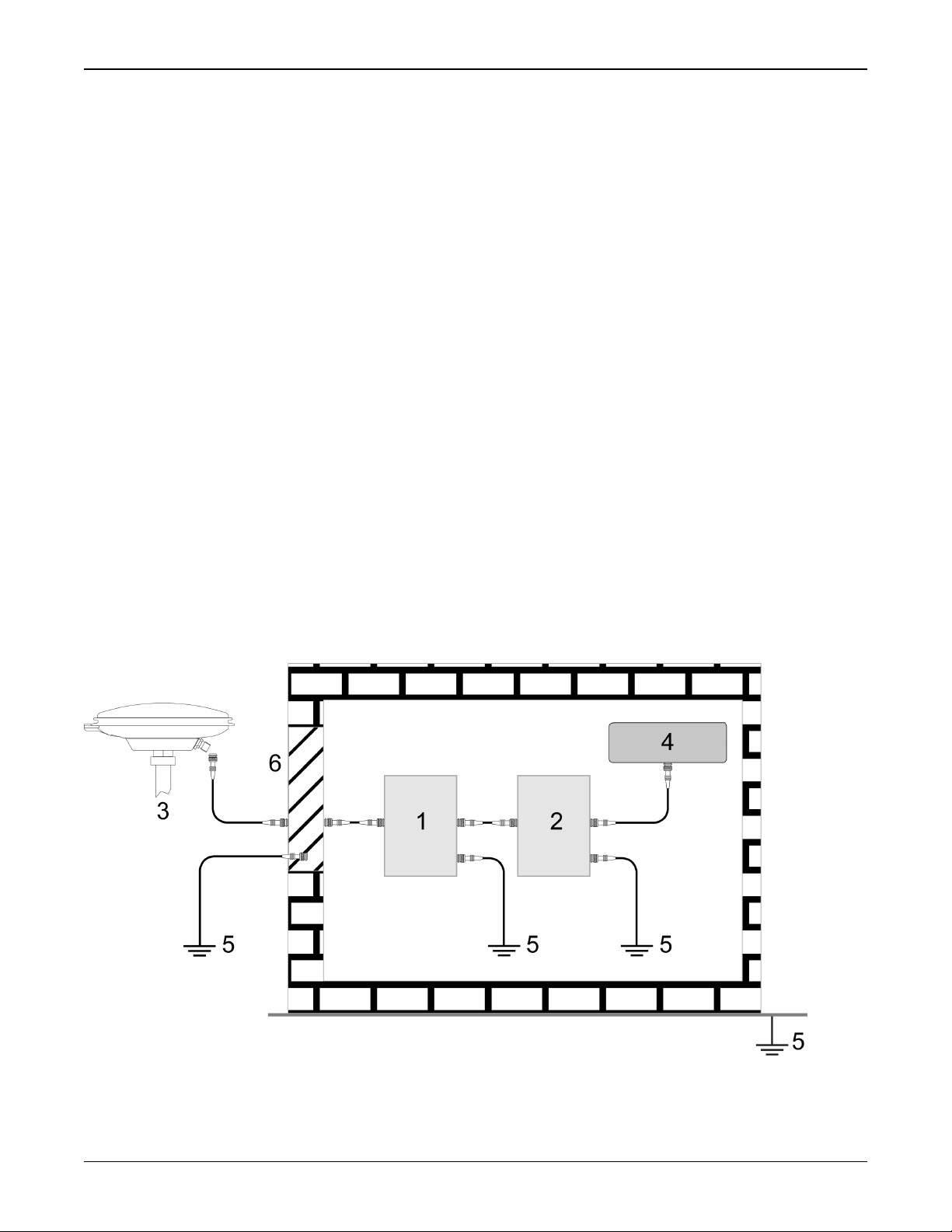
6.
The primary and secondary lightning protections should be as close to the building's entrance
as possible. Where feasible, mount onto the grounding plate itself (refer to the figure
below).
OEM7 SPAN Installation and Operation User Manual v1 10
Notices
Ref# Description
1 Primary lightning protection device
2 Secondary lightning protection device
3 External antenna
4 GNSS Receiver
5 To ground
6 Grounding plate or grounding point at the building’s entrance
Acceptable choices for earth grounds, for central buildings, are:
l
Grounded interior metal cold water pipe within five feet (1.5 m) of the point where
it enters the building
l
Grounded metallic service raceway
l
Grounded electrical service equipment enclosure
l
Eight-foot grounding rod driven into the ground (only if bonded to the central building ground by #6, or heavier, bonding wire)
These installation instructions are the minimum requirements for receiver and antenna installations.
Where applicable, follow the electrical codes for the country of installation. Examples of country
codes include:
l
USA National Electrical Code (NFPA 70)
l
Canada Canadian Electrical Code (CSA C22)
l
UK British Standards Institute (BSI 7671)
Conventions
The following conventions are used in this manual:
Information that supplements or clarifies text.
A caution that actions, operation or configuration may lead to incorrect or improper
use of the hardware.
A warning that actions, operation or configuration may result in regulatory
noncompliance, safety issues or equipment damage.
OEM7 SPAN Installation and Operation User Manual v1 11
Customer Support
NovAtel Knowledge Base
If you have a technical issue, visit the NovAtel Support page at www.novatel.com/support.
Through the Support page, you can contact Customer Support, find papers and tutorials or down-
load current manuals and the latest firmware.
Before Contacting Customer Support
Before you contact NovAtel Customer Support about a software problem, perform the following
steps:
If logging data over an RS-232 serial cable, ensure that the configured baud rate can support the data bandwidth (see SERIALCONFIG command). NovAtel recommends a min-
imum suggested baud rate of 115200 bps.
1.
Log the following data to a file on your computer for 15 minutes:
RXSTATUSB once
RAWEPHEMB onchanged
GLORAWEPHEMB onchanged
BESTPOSB ontime 1
RANGEB ontime 1
RXCONFIGA once
VERSIONA once
For SPAN systems, include the following logs in the file created on your computer:
RAWIMUSXB onnew
INSUPDATESTATUSB onnew
INSPVAXB ontime 1
INSCONFIGA once
2.
Send the data file to NovAtel Customer Support: support@novatel.com
3.
You can also issue a FRESET command to the receiver to clear any unknown settings.
The FRESET command will erase all user settings. You should know your configuration
(by requesting the RXCONFIGA log) and be able to reconfigure the receiver before you
send the FRESET command.
If you are having a hardware problem, send a list of the troubleshooting steps taken and the results.
Contact Information
Log a support request with NovAtel Customer Support using one of the following methods:
Log a Case and Search Knowledge:
OEM7 SPAN Installation and Operation User Manual v1 12

Customer Support
Website: www.novatel.com/support
Log a Case, Search Knowledge and View Your Case History: (login access required)
Web Portal: https://novatelsupport.force.com/community/login
E-mail:
support@novatel.com
Telephone:
U.S. and Canada:1-800-NOVATEL (1-800-668-2835)
International:+1-403-295-4900
OEM7 SPAN Installation and Operation User Manual v1 13

Chapter 1 Introduction to SPAN technology
NovAtel's SPAN technology brings together two very different but complementary positioning
and navigation systems namely Global Navigation Satellite System (GNSS) and an Inertial Navigation System (INS). By combining the best aspects of GNSS and INS into one system, SPAN
technology is able to offer a solution that is more accurate and reliable than either GNSS or INS
could provide alone. The combined GNSS+INS solution has the advantage of the absolute accuracy available from GNSS and the continuity of INS through traditionally difficult GNSS conditions.
The SPAN system consists of the following components:
l
NovAtel OEM7 receiver
These receivers are capable of receiving and tracking different combinations of GPS,
GLONASS, Galileo and BeiDou signals on a maximum of 555 channels. OEM7 family receivers can also allocate channels for the reception of correction service signals from SBAS
(standard) and NovAtel Correct™with PPP (optional). OEM7 adaptability offers multi-system,
frequency, and size configurations for any application requirement. Patented Pulsed Aperture Correlator (PAC) technology combined with a powerful microprocessor enable multipath-resistant processing. Excellent acquisition and re-acquisition times allow this receiver
to operate in environments where very high dynamics and frequent interruption of signals
can be expected. The OEM7 family also supports the timing requirements of the IMU and
runs the real-time INS filter.
l
IMU
The Inertial Measurement Unit (IMU) consists of three accelerometers and three gyroscopes
(gyros) so that accelerations along specific axis and angular rotations can be measured.
Several IMU types are supported and are listed in Table 1: SPAN-Compatible IMU Models on
the next page.
l
GNSS antenna
l
Computer Software
Real-time data collection, status monitoring and receiver configuration is possible through
the NovAtel Connect™software utility, see SPAN Configuration with NovAtel Connect on
page52.
The GNSS receiver is connected to the IMU with an RS-232, RS-422 or SPI link. A NovAtel GNSS
antenna must also be connected to the receiver to track GNSS signals. After the IMU enclosure,
GNSS antenna and appropriate power supplies are attached, and a few simple configuration commands are entered, the SPAN system will be ready to navigate.
1.1 Fundamentals of GNSS+INS
GNSS positioning observes range measurements from orbiting GNSS satellites. From these
observations, the receiver can compute position and velocity with high accuracy. NovAtel GNSS
positioning systems are highly accurate positioning tools. However, GNSS in general has some
restrictions which limit its usefulness in some situations. GNSS positioning requires line of sight
view to at least four satellites simultaneously. If these criteria are met, differential GNSS positioning can be accurate to within a few centimetres. If however, some or all of the satellite signals are blocked, the accuracy of the position reported by GNSS degrades substantially, or may
not be available at all.
OEM7 SPAN Installation and Operation User Manual v1 14
Chapter 1 Introduction to SPAN technology
In general, an INS uses forces and rotations measured by an IMU to calculate position, velocity
and attitude. This capability is embedded in the firmware of OEM7 series receivers. Forces are
measured by accelerometers in three perpendicular axes within the IMU and the gyros measure
angular rotation rates around those axes. Over short periods of time, inertial navigation gives
very accurate acceleration, velocity and attitude output. The INS must have prior knowledge of
its initial position, initial velocity, initial attitude, Earth rotation rate and gravity field. Since the
IMU measures changes in orientation and acceleration, the INS determines changes in position
and attitude, but initial values for these parameters must be provided from an external source.
Once these parameters are known, an INS is capable of providing an autonomous solution with
no external inputs. However, because of errors in the IMU measurements that accumulate over
time, an inertial-only solution degrades with time unless external updates such as position, velocity or attitude are supplied.
The SPAN system’s combined GNSS+INS solution integrates the raw inertial measurements
with all available GNSS information to provide the optimum solution possible in any situation. By
using the high accuracy GNSS solution, the IMU errors can be modeled and mitigated. Conversely, the continuity and relative accuracy of the INS solution enables faster GNSS signal reacquisition and RTK solution convergence.
The advantages of using SPAN technology are its ability to:
l
Provide a full attitude solution (roll, pitch and azimuth)
l
Provide continuous solution output (in situations when a GNSS-only solution is impossible)
l
Provide faster signal reacquisition and RTK solution resolution (over stand-alone GNSS
because of the tightly integrated GNSS and INS filters)
l
Output high-rate (up to 200 Hz depending on your logging selections) position, velocity and
attitude solutions for high-dynamic applications, see also Logging Restriction Important
Notice on page60
l
Use raw phase observation data (to constrain INS solution drift even when too few satellites
are available for a full GNSS solution)
For more information about GNSS and INS, refer to www.novatel.com/an-introduction-
to-gnss/
1.2 Models and Features
All SPAN system receivers are factory configurable for L1/L2 RTK capability and are compatible
with an IMU. See Table 1: SPAN-Compatible IMU Models below for firmware model details.
Table 1: SPAN-Compatible IMU Models
Model Name Compatible IMUs SW Model
IMU-CPT IMU-CPT S1
IMU-FSAS-EI iIMU-FSAS S3
IMU-H1900-CA50 HG1900-CA50 S2
OEM7 SPAN Installation and Operation User Manual v1 15

Chapter 1 Introduction to SPAN technology
Model Name Compatible IMUs SW Model
IMU-H1930-CA50 HG1930-CA50 S1
IMU-H58 HG1700-AG58 S2
IMU-H62 HG1700-AG62 S2
IMU-IGM-A1 IMU-IGM-A1 S1
IMU-IGM-S1 IMU-IGM-S1 S1
IMU-ISA-100C ISA-100C S3
IMU-KVH1725 KVH-1725 S2
IMU-KVH1750 KVH-1750 S2
IMU-LN200 LN-200 S3
IMU-µIMU Lifef µIMU S2
OEM-IMU-ADIS-16488 OEM-IMU-ADIS-16488 S1
OEM-IMU-G320 OEM-IMU-G320 S1
OEM-IMU-ISA-100C OEM-IMU-ISA-100C S3
OEM-IMU-STIM300 OEM-IMU-STIM300 S1
UIMU-H58 HG1700-AG58 S2
UIMU-H62 HG1700-AG62 S2
Each model is capable of multiple positioning modes of operation.
Each model has the following standard features:
l
NovAtel's advanced OEM7 multi-frequency, multi-constellation receiver
l
Full-duplex COM ports which support data transfer rates of up to 460,800 bits/s1.
One of these serial ports is capable of communication with an IMU
l
USB 2.0 port
l
Ethernet port
l
Controller Area Network Bus (CAN Bus) which is a rugged differential serial bus with a protocol that provides services for processes, data and network management.
l
Field-upgradeable firmware (program software). This unique feature means that the firmware can be updated any time, anywhere, without any mechanical procedures whatsoever.
Firmware upgrades can include changes in the software model to enable additional features
or signals. For example, a model with L1/L2-only capabilities can be upgraded to a model
with L1/L2 and NovAtel CORRECT with RTK™ in only a few minutes in your office (instead of
the days or weeks that would be required if the receiver had to be sent to a service depot).
1
Rates higher than 115,200 are not standard on most computers and may require extra computer hardware.
OEM7 SPAN Installation and Operation User Manual v1 16

Chapter 1 Introduction to SPAN technology
All that is required to unlock the additional features is a special authorization code. Refer to
the OEM7 Installation and Operation User Manual (OM-20000168) for further details on this
topic.
Some of the IMUs used with SPAN are housed in an enclosure with a PCB board to handle power,
communication and data timing. See IMU Technical Specifications on page83 for details.
1.3 Related Documents and Information
This manual contains sufficient information about the installation and operation of the SPAN system. It is beyond the scope of this manual to provide details on service or repair. Contact your
local NovAtel dealer for any customer service related inquiries, see Customer Support on
page12.
The OEM7 receiver utilizes a comprehensive user-interface command structure, which requires
communications through its communications ports. For descriptions of the commands and logs
available with OEM7 family products, refer to the OEM7 Commands and Logs Reference Manual
(OM-20000169) available on the NovAtel website at www.novatel.com/support/. It is recommended that these documents be kept together for easy reference.
For more information about the OEM7 receivers, refer to the OEM7 Installation and Operation
User Manual (OM-20000168).
SPAN system output is compatible with post-processing software from NovAtel's Waypoint
Products Group. Visit our web site at www.novatel.com for details.
®
OEM7 SPAN Installation and Operation User Manual v1 17
Chapter 2 SPAN Installation
2.1 Hardware Description
One hardware setup consists of an OEM7 receiver, an IMU, a GNSS antenna, power and a communication link (if your application requires real time differential operation).
If your IMU enclosure and IMU were supplied separately, additional instructions for
installing the IMU into an the enclosure are available in the following appendices:
HG1700 IMU in Universal Enclosure on page206, LN-200 IMU in Universal
Enclosure on page217, HG1700 IMU in SPAN HG Enclosure on page224 and LN-200
IMU in SPAN IMU Enclosure on page231.
Another hardware set up consists of a receiver, an IMU, an IMU interface card, a GNSS antenna
and a COM and power link. The IMU interface card can be a MEMS Interface Card (MIC) (refer to
MIC Set Up on page22) or a Universal IMU Controller (UIC) (refer to UIC Set Up on page33).
2.2 Hardware Set Up
Complete the following steps to set up your NovAtel SPAN system.
1.
Mount the GNSS antenna.
See Mounting the GNSS Antenna below for details.
2.
Mount the IMU.
See Mount the IMU on the next page for details.
3.
Install the OEM7 receiver.
See the OEM7 Installation and Operation User Manual (OM-20000168) for information about
installing an OEM7 receiver.
4.
Connect the GNSS antenna to the OEM7 receiver.
See the OEM7 Installation and Operation User Manual (OM-20000168) for information about
installing an OEM7 receiver.
5.
Connect the IMU to the OEM7 receiver.
See Connect the IMU to the OEM7 Receiver on the next page for details.
6.
Connect the I/O strobe signals (optional).
See the OEM7 Installation and Operation User Manual (OM-20000168) for information about
installing an OEM7 receiver.
7.
Connect power to the IMU and receiver.
See Connect Power on page21 for details.
2.2.1 Mounting the GNSS Antenna
The OEM7 receiver is designed to operate with any of the NovAtel single, dual and triple-frequency GNSS antenna models.
When installing the antenna:
OEM7 SPAN Installation and Operation User Manual v1 18
Chapter 2 SPAN Installation
l
Choose an antenna location with a clear view of the sky so each satellite above the horizon
can be tracked without obstruction. For more information on RF signal propagation and multipath, refer to the NovAtel application note APN-008 Discussions on RF Signal Propagation
and Multipath at www.novatel.com/support/.
l
Mount the antenna on a secure, stable structure capable of safe operation in the specific
environment.
l
Ensure the antenna cannot move due to dynamics.
2.2.2 Mount the IMU
Mount the IMU in a fixed location where the distance from the IMU to the GNSS antenna phase
center is constant. Ensure that the orientation with respect to the vehicle and antenna is also constant.
For attitude output to be meaningful, the IMU should be mounted such that the positive Z-axis
marked on the IMU enclosure points up and the Y-axis points forward through the front of the
vehicle, in the direction of track. If the IMU is not mounted in this orientation, a rotational offset
must applied. See Rotational Offsets on page44 for more information.
Also, it is important to measure the distance from the IMU to the antenna (the Antenna Lever
Arm), on the first usage, on the axis defined on the IMU enclosure. See Lever Arm Calibration
Routine on page60. See also IMU Technical Specifications on page83 for dimensional drawings
of the IMU enclosures.
Ensure the IMU cannot move due to dynamics and that the distance and relative direction
between the antenna and the IMU is fixed. See SPAN Configuration on page49.
The closer the antenna is to the IMU, particularly in the horizontal plane, the more
accurate the position solution. Also, your measurements entered using the
SETINSTRANSLATION command must be as accurate as possible, or at least more
accurate than the GNSS positions being used. For example, a 10 cm error in
recording the antenna offset will result in at least a 10 cm error in the
output. Millimeter accuracy is preferred.
The offset from the IMU to the antenna, and/or a user point device, must remain
constant especially for RTK or DGPS data. Ensure the IMU, antenna and user point
device are bolted in one position perhaps by using a custom bracket.
2.2.3 Connect the IMU to the OEM7 Receiver
Connect the IMU to the receiver using the IMU interface cable.
For a system with a OEM7 receiver card:
l
A wiring harness is required between the receiver card and the IMU interface cable. For
more information, see the OEM7 Installation and Operation User Manual (OM-20000168).
If using a KVH1725 or KVH1750 IMU, the baud rate of the IMU must be
changed to 460,800 bps. For information about changing the IMU baud rate,
see IMU Direct Connection on the next page.
OEM7 SPAN Installation and Operation User Manual v1 19
Chapter 2 SPAN Installation
KVH1725 and KVH1750 Baud Rate Conversion
The maximum baud rate of the COM ports on an OEM7 receiver is 460,800 bps. The KVH1750
and KVH1725 IMUs natively communicate at 921,600 bps, so they need to be modified to use
460,800 bps.
Though slower, 460,800 bps is more than adequate to transmit the data at the
required 200 Hz without any impact to performance.
There are two methods to change the KVH17xx series IMU baud rate. If an OEM6 receiver is
available, a command is available that will allow the receiver to change the IMU baud rate. If
not, a direct RS-422 connection at 921,600 baud is required to change the IMU baud rate.
IMU Direct Connection
This method requires a direct connection to the IMU at 921,600 baud over RS-
422.Make sure the RS-422 link used is capable of 921,600 baud as not all serial
ports are capable of that rate.
1.
Open a command terminal at 921600 baud via an RS-422 serial link.
By default, the IMU will output 0.5 Hz binary messages which will help confirm you are connected properly.
2.
Issue the following two commands in sequence to enter configuration mode and change the
baud rate.
=CONFIG,1
=BAUD,460800
3.
Upon completion of these commands, power cycle the IMU to boot up in the new baud rate.
4.
Confirm the change by connecting to the IMU at 460,800 baud and verifying the incoming
messages.
The new baud rate configuration is saved to the IMU NVM automatically so the process is complete
and the IMU is ready for use with an OEM7 receiver.
Use an OEM6 Receiver Command
OEM6 firmware as of version OEM060630RN0000 (Dec 2016) includes the
IMUCONFIGURATION command that internally configures the KVH17xx IMU for SPAN communication. Three sets of configuration options are available, two of which will allow user to
change the baud rate of the IMU to either 921,600 or 460,800. This provides customers upgrading to OEM7 an easy method to modify the baud rate. To change the IMU to 460800 baud, use
the following procedure:
1.
Connect the KVH-17xx IMU (IMU-KVH1750 or IMU-KVH1725) to an RS422 capable OEM6
receiver communication port.
2.
Issue the following command.
CONNECTIMU COM# IMU_KVH_17xx
3.
Issue the following command.
IMUCONFIGURATION IMU_KVH_17xx 2
OEM7 SPAN Installation and Operation User Manual v1 20
Chapter 2 SPAN Installation
The IMUCONFIGURATION command can be used to configure the KVH17xx IMU’s depending
on the value of the Option field.
IMUCONFIGURATION IMUType [Option]
IMU Type Option Configuration Details
0 Configure KVH options for NovAtel communication.
IMU_KVH_1750
IMU_KVH_1725
1 Change KVH baud rate to 921,600
2 Change KVH baud rate to 460,800
2.2.4 Connect Power
If you are using a MEMS OEM IMU (ADIS-16488, HG1900, HG1930, STIM300) and a
MIC, see MIC Set Up on the next page for information about connecting and
powering the MIC and IMU.
If you are using an OEM IMU (ISA-100C, HG1900, LN200 or µIMU) and a UIC, see
UIC Set Up on page33 for information about connecting and powering the UIC and
IMU.
Receiver Power
For information about connecting power to an OEM7 receiver, see the OEM7 Installation and
Operation User Manual (OM-20000168).
IMU Power
In addition to the receiver power supply, a power supply is needed for the IMU. See Table 2:
IMU Power Supply below for the voltage requirements for each IMU. The same power supply can
be used for the receiver and the IMU, if the power supply meets the power requirements of both
devices.
Table 2: IMU Power Supply
IMU Power Requirement
UIMU-LN200 +12 to +28 V DC
IMU-ISA-100C +10 to +34 V DC
UIMU-HG1700 (AG58 or AG62) +12 to +28 V DC
IMU-KVH-1725 +9 to +36 V DC
IMU-KVH1750 +9 to +36 V DC
IMU-FSAS +10 to +34 V DC
IMU-CPT +9 to +18 V DC
IMU-IGM +10 to +30 V DC
OEM7 SPAN Installation and Operation User Manual v1 21

Chapter 2 SPAN Installation
For most IMUs, connect the power leads on the IMU interface cable to the IMU power supply.
For an IMU in the IMU Enclosure (IMU-HG1900, IMU-ISA-100C, IMU-LN200 or IMU-µIMU), connect the IMU Power Cable (NovAtel part # 60723136) from the IMU to the IMU power supply.
Details about the IMU ports and cables can be found in IMU Technical Specifications on page83.
2.3 MIC Set Up
For IMUs that are not mounted inside a NovAtel IMU enclosure (e.g. OEM-HG1930), an interface
card is required to connect the IMU to the OEM7 receiver. The MEMS Interface Card (MIC)
provides the connection between OEM7 receiver cards and Micro Electromechanical Systems
(MEMS) IMUs.
IMUs have different interface requirements. Use a MIC to connect MEMS IMUs
(ADIS-16488, HG-1700, HG-1900, HG-1930 or STIM-300) to an OEM7 receiver. For
other supported IMUs (e.g. ISA100C, LN200, HG-1900 or µIMU), use a Universal
IMU Controller (UIC). See UIC Set Up on page33.
There are two MIC configurations: stack up and standalone. In a stack up configuration, the MIC
card is mounted on an OEM719 receiver. In a standalone configuration, the MIC is mounted separately from the receiver.
The MIC supports all OEM7 receiver cards for communications. The OEM719 is the only
OEM7 receiver card that can be directly integrated and powered by the MIC.
2.3.1 Install a MIC in a Stack Up Configuration
In a stack up configuration, the MIC is connected to an OEM719 receiver using the 20-pin header
on the OEM719. Power and communications connections to the receiver are made through the
MIC.
Important! Assemble in accordance with applicable industry standards. Ensure all
Electrostatic Discharge (ESD) measures are in place, in particular, use a ground strap
before exposing or handling any electronic items, including the MIC, receiver and IMU.
Take care to prevent damaging or marring painted surfaces, O-rings, sealing surfaces
and the IMU.
For more information about ESD practices, see the OEM7 Installation and Operation
User Manual (OM-20000168).
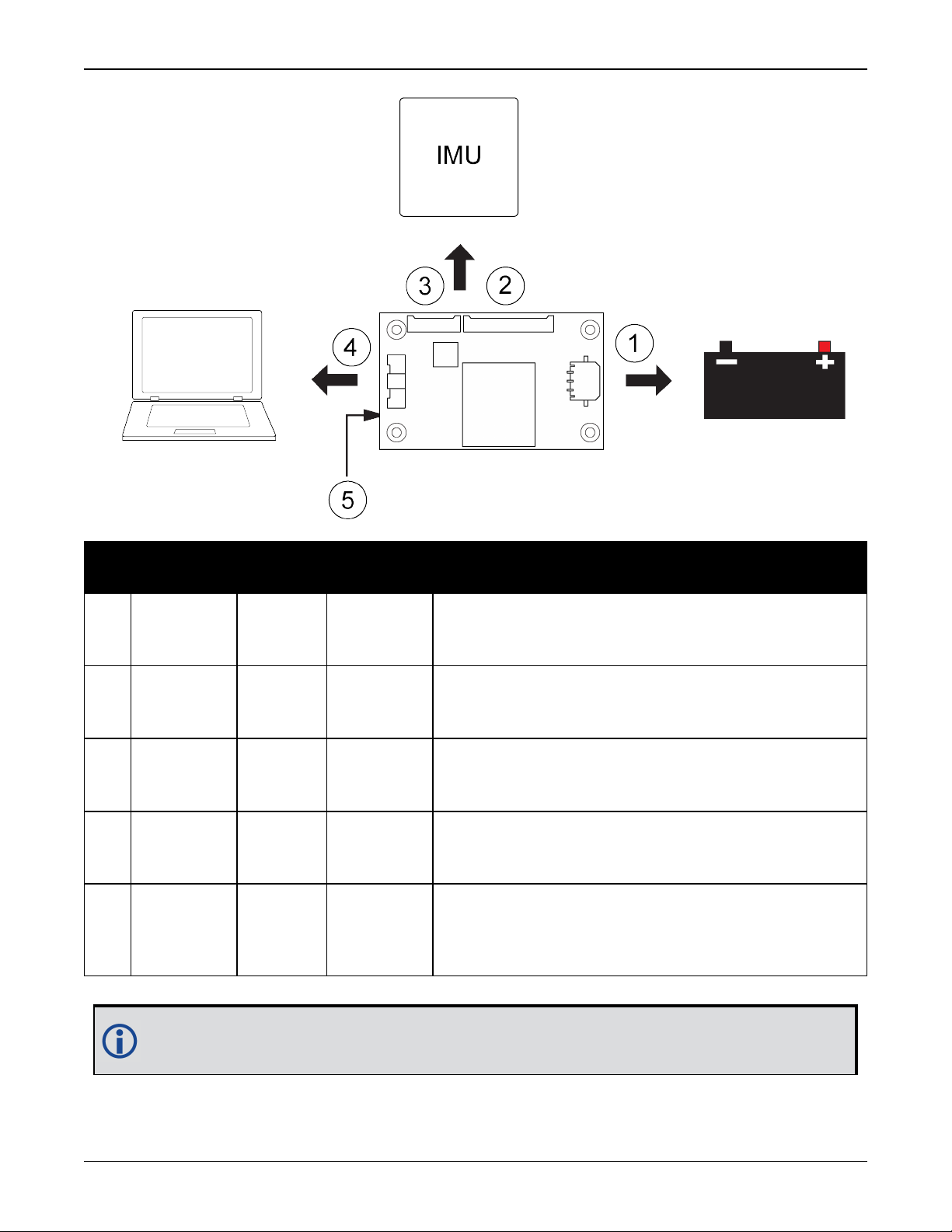
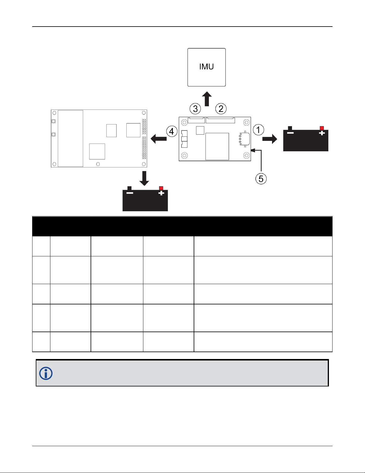
Figure 1: Basic Set Up – MIC in Stack Up Configuration
OEM7 SPAN Installation and Operation User Manual v1 22
Chapter 2 SPAN Installation
Ref Connector
1 P101
2 P601
3 P701
4 P301
5 J301
Part
Number
436500313
(Molex)
537802070
(Molex)
537801070
(Molex)
5015713007
(Molex)
ASP16357701
(Samtec)
Mating
Connector
436450300
(Molex)
511462000
(Molex)
511461000
(Molex)
5011893010
(Molex)
N/A
Description
Connects to the MIC power supply.
This connection provides power to the MIC and the
OEM719 receiver. (user supplied cable)
Connects to HG1700, HG1900, HG1930 and STIM300
IMUs. (NovAtel supplied cable kit)
Connects to ADIS-16488 IMUs.
(NovAtel supplied cable kit)
Connects the MIC and OEM719 communication signals
to the user system. (user supplied cable)
Connects to the main connector (P1701) on an
OEM719 receiver. J301 is on the bottom of the MIC
card
For information about the MIC connectors and pin-outs, see MIC Connectors on
page187.
OEM7 SPAN Installation and Operation User Manual v1 23
Chapter 2 SPAN Installation
For information about the OEM7 receiver card connectors and pinouts, refer to the OEM7
Installation and Operation User Manual (OM-20000168).
Use the following steps to install the OEM719 receiver and MIC:
1.
Mount the components of the SPAN system. See Mount the SPAN System Components below.
2.
Connect the IMU to the MIC. See Connect the IMU to the MIC on page30.
3.
Connect power to the MIC. See Connect Power to the MIC on page27.
4.
Connect the input and output signals to the MIC. See Connect the Input and Output Signals on
page27.
Mount the SPAN System Components
1.
Mount the antenna. See Mounting the GNSS Antenna on page18.
2.
Use the standoffs supplied with the MIC card to secure the OEM719 to its mounting location.
See Figure 17, Mount the MIC on the OEM615 on page 44.
See the OEM7 Installation and Operation User Manual (OM-20000168) for information about
installing an OEM7 receiver.
The part number for the recommended standoffs is RAF-M21073005AL7 (Irwin
Industrial).
If alternate standoffs are selected, use equivalent parts with a minimum height of
12 mm.
Ensure all standoffs are properly installed and the mounting location is flat.
The amount of board deflection (bow and twist) must not exceed 0.75%. For
example, on the MIC which is 75 mm long and 46 mm wide, the deflection along
the length must not exceed 0.56 mm and the deflection along the width must not
exceed 0.34 mm.
Ensure the MIC is mounted close enough to the IMU so the interface cable can
reach both devices.
3.
Connect the antenna cable to the antenna jack on the OEM719.
The antenna cable must have a right angle MCX connector on the end that connects to the
OEM719.
Warning! Do not apply power to the cards until the antenna cable is attached.
OEM7 SPAN Installation and Operation User Manual v1 24
Chapter 2 SPAN Installation
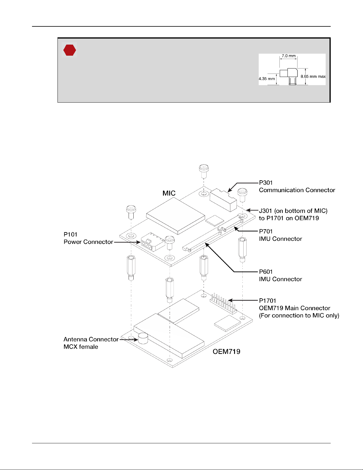
The part number for the recommended MCX connector
is M1051-110 (ShinA Telecom). If an alternate part is
used, it should meet the dimensions shown in the
diagram.
The space between the OEM719 and the MIC is limited.
The height of the MCX connector must not exceed 8.65
mm.
4.
Align the mating connector (J301) on the MIC with the 20-pin header (P1701) on the OEM719.
Make sure all of the pins on the header are aligned with the holes in the mating connector.
Press down on the MIC to seat the connector on the header.
5.
Use the four screws supplied with MIC to secure the MIC card to the OEM719.
Figure 2: Mount the MIC on the OEM719
Connect the IMU to the MIC
1.
Attach the IMU mounting Printed Circuit Board (PCB) to the IMU.
Ensure all the pins on the header are aligned with the holes on the mating connector.
OEM7 SPAN Installation and Operation User Manual v1 25
Chapter 2 SPAN Installation
2.
Mount the IMU. See Mount the IMU on page19.
3.
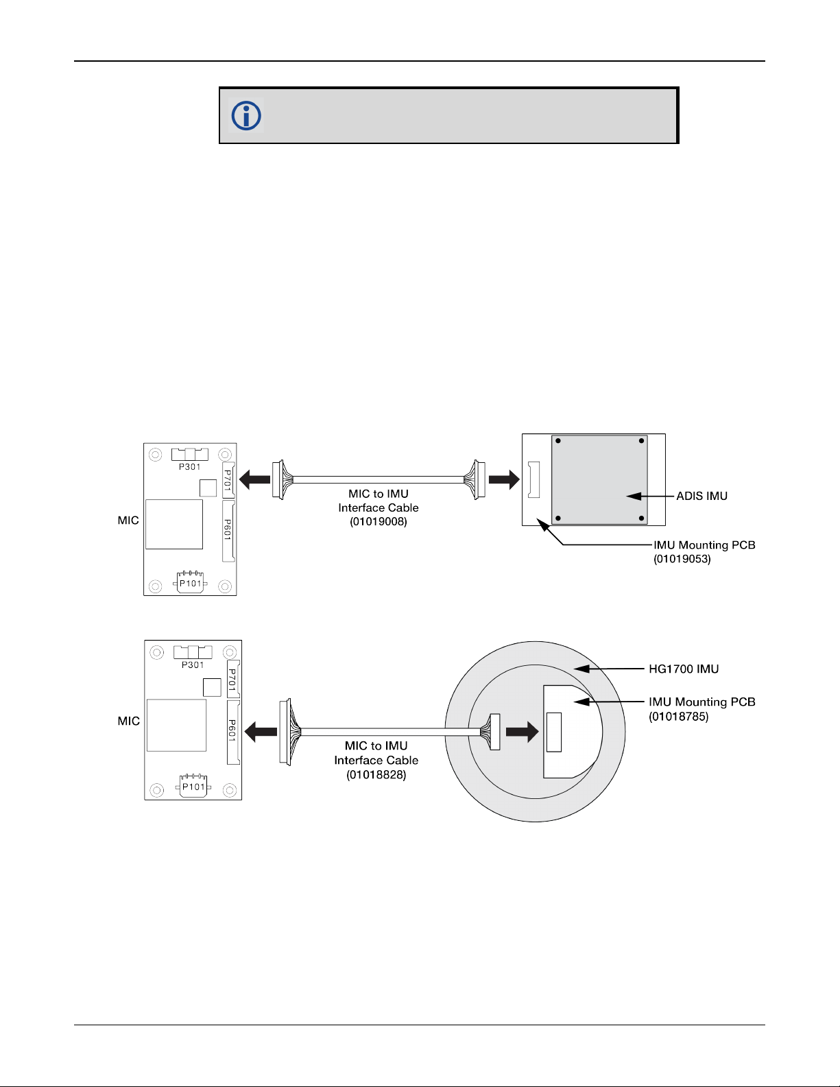
Connect the IMU-to-MIC interface cable to the IMU.
4.
Connect the IMU-to-MIC interface cable to the IMU connector on the MIC.
l
Use the 10 pin locking connector (P701) for the ADIS IMUs.
See Figure 3: Connect the ADIS IMU to the MIC (OEM Cable Kit: 01019007) below.
l
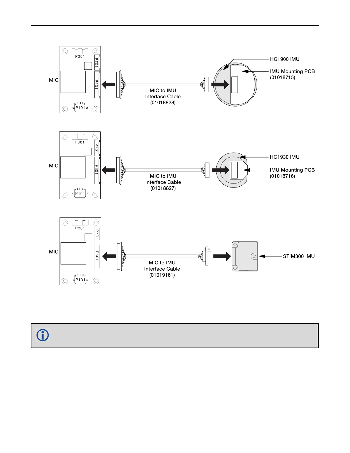
Use the 20 pin locking connector (P601) for the HG1700, HG1900, HG1930 or STIM300
IMU.
See Figure 4: Connect the HG1700 IMU to the MIC (OEM Cable Kit: 01018868) below, Fig-
ure 5: Connect the HG1900 IMU to the MIC (OEM Cable Kit: 01018871) on the next page,
Figure 6: Connect the HG1930 IMU to the MIC (OEM Cable Kit: 01018869) on the next
page or Figure 7: Connect the STIM300 IMU to the MIC (OEM Cable Kit: 01019174) on
the next page.
Figure 3: Connect the ADIS IMU to the MIC (OEM Cable Kit: 01019007)
An IMU mounting PCB is not used with the STIM300 IMU.
Figure 4: Connect the HG1700 IMU to the MIC (OEM Cable Kit: 01018868)
OEM7 SPAN Installation and Operation User Manual v1 26
Chapter 2 SPAN Installation
Figure 5: Connect the HG1900 IMU to the MIC (OEM Cable Kit: 01018871)
Figure 6: Connect the HG1930 IMU to the MIC (OEM Cable Kit: 01018869)
Figure 7: Connect the STIM300 IMU to the MIC (OEM Cable Kit: 01019174)
Connect Power to the MIC
Connect a +10 to +30 V DC power supply to the power connector (P101) on the MIC. See MIC
Connectors on page187 for pinout information for the power connector.
This connection provides power to the MIC and the OEM719.
Connect the Input and Output Signals
All of the communication connections to the MIC and the OEM719 receiver are available on the
communications connector (P601) on the MIC. These connections include:
l
MIC serial port
l
OEM615 serial port (COM2)
OEM7 SPAN Installation and Operation User Manual v1 27
Chapter 2 SPAN Installation
l
USB port
l
Event1 trigger input
l
Event2 trigger input
l
1 PPS (Pulse Per Second) output
l
VARF (Variable Frequency) output
l
Reset input
l
Position Valid output
See MIC Connectors on page187 for the pinouts of the communications connector.
All signal I/O with the exception of the USB port are at LVTTL levels. To connect the MIC
to devices that use other signals levels, such as a computer with an RS-232 serial port,
an interface circuit that converts LVTTL to the other signal level must be used.
Use a twisted pair for the USB port connection and keep the wires as short as possible.
2.3.2 Install a MIC in a Standalone Configuration
Ina standalone configuration, the MIC is mounted separately from the OEM7 receiver.
Important! Assemble in accordance with applicable industry standards. Ensure all
Electrostatic Discharge (ESD) measures are in place, in particular, use a ground strap
before exposing or handling any electronic items, including the MIC, receiver and IMU.
Take care to prevent damaging or marring painted surfaces, O-rings, sealing surfaces
and the IMU.
For more information about ESD practices, see the OEM7 Installation and Operation
User Manual (OM-20000168).
OEM7 SPAN Installation and Operation User Manual v1 28
Chapter 2 SPAN Installation
Figure 8: Basic MIC Set Up
Ref Connector Part Number
1 P101
2 P601
3 P701
4 P301
5 J301
43650-0313
(Molex)
53780-2070
(Molex)
53780-1070
(Molex)
501571-3007
(Molex)
ASP-163577-01
(Samtec)
For information about the MIC connectors and pin-outs, see MIC Connectors on
page187.
Mating Con-
nector
43645-0300
(Molex)
51146-2000
(Molex)
51146-1000
(Molex)
501189-3010
(Molex)
Connects to the MIC power supply.
(user supplied cable)
Connects to HG1700, HG1900, HG1930 and
STIM300 IMUs.
(NovAtel supplied cable)
Connects to ADIS-16488 IMUs.
(NovAtel supplied cable)
Connects the MIC serial port to the OEM7
receiver.
(user supplied cable)
Description
N/A This connector is not used.
OEM7 SPAN Installation and Operation User Manual v1 29
Chapter 2 SPAN Installation
For information about the OEM7 receiver card connectors and pinouts, refer to the OEM7
Installation and Operation User Manual (OM-20000168).
OEM729 Recommendations
l
Use COM1 for connection to a computer. COM1 uses RS-232 levels and can be connected to a computer without additional interface circuitry.
l
Use COM2 for connection to the MIC serial port. Both the MIC serial port and COM2
use LVCMOS levels and can be connected without additional interface circuitry.
Use the following steps to install the OEM7 receiver and MIC:
1.
Mount the components of the SPAN system. See Mount the SPAN System Components below.
2.
Connect the IMU to the MIC. See Connect the IMU to the MIC below.
3.
Connect the MIC to the OEM7 receiver. See Connect the MIC to a Receiver on page32.
4.
Connect power to the MIC and OEM7 receiver. See Connect Power to the MIC and OEM7
Receiver on page33.
Mount the SPAN System Components
1.
Mount the antenna. See Mounting the GNSS Antenna on page18.
2.
Mount OEM7 receiver. See the OEM7 Installation and Operation User Manual (OM-20000168)
for information about installing an OEM7 receiver.
3.
Install the MIC in a secure enclosure to reduce environmental exposure and RF interference.
If there is sufficient space, the MIC can reside in the same enclosure as the receiver.
Use the screws supplied with the MIC card to secure the MIC to its mounting location. See
MIC Mechanical Drawings on page185 for the MIC dimensions.
Ensure the MIC is mounted close enough to the IMU so the interface cable can
reach both devices.
Ensure all standoffs are properly installed and the mounting location is flat.
The amount of board deflection (bow and twist) must not exceed 0.75%. For
example, on the MIC which is 75 mm long and 46 mm wide, the deflection along
the length must not exceed 0.56 mm and the deflection along the width must not
exceed 0.34 mm.
4.
Mount the IMU. See Mount the IMU on page19.
Connect the IMU to the MIC
1.
Attach the IMU mounting Printed Circuit Board (PCB) to the IMU.
Ensure all the pins on the header are aligned with the holes on the mating connector.
OEM7 SPAN Installation and Operation User Manual v1 30
 Loading...