

Novatel OEM719, OEM729, OEM7500, OEM7700, OEM7720 Installation And Operation Manual
...
OEM7®SPAN
®
Installation and Operation
User Manual
OM-20000170 v4 February 2018

OEM7 SPAN Installation and Operation User Manual
Publication Number: OM-20000170
Revision Level: v4
Revision Date: February 2018
Firmware Version: 7.04 / OM7MR0400RN0000
Warranty
NovAtel Inc. warrants that its GNSS products are free from defects in materials and workmanship, subject to the conditions set forth on our web site: www.nova-
tel.com/products/warranty/ and for the following time periods:
OEM7®Receivers One (1) Year
GNSS Antenna Series One (1) Year
Cables and Accessories Ninety (90) Days
Software Warranty One (1) Year
Return instructions
To return products, refer to the instructions found at: www.novatel.com/warranty-return.
Proprietary Notice
Information in this document is subject to change without notice and does not represent a commitment on the part of NovAtel Inc. The software described in this document is furnished under
a licence agreement or non-disclosure agreement. The software may be used or copied only in
accordance with the terms of the agreement. It is against the law to copy the software on any
medium except as specifically allowed in the license or non-disclosure agreement.
No part of this manual may be reproduced or transmitted in any form or by any means, electronic or mechanical, including photocopying and recording, for any purpose without the express
written permission of a duly authorized representative of NovAtel Inc.
The information contained within this manual is believed to be true and correct at the time of
publication.
NovAtel, OEM7, PwrPak7, SPAN, ALIGN, VEXXIS, Inertial Explorer and Waypoint are registered
trademarks of NovAtel Inc.
OEM719, OEM729, OEM7500, OEM7700, OEM7720, NovAtel CORRECT and NovAtel Connect are
trademarks of NovAtel Inc.
All other product or brand names are trademarks of their respective holders.
© Copyright 2018 NovAtel Inc. All rights reserved. Unpublished rights reserved under International copyright laws.
OEM7 SPAN Installation and Operation User Manual v4 2

Table of Contents
Figures
Tables
Notices Receiver Card
Customer Support
Chapter 1 OEM7 SPAN Overview
1.1 Fundamentals of GNSS+INS 23
1.2 Models and Features 24
1.2.1 INS Options 24
1.2.2 IMU Grade 25
1.3 Related Documents and Information 26
Chapter 2 SPAN Installation
2.1 OEM7 Receiver Card Installation 27
2.1.1 Selecting a GNSS Antenna 29
2.1.2 Choosing a Coaxial Cable 29
2.1.3 Mounting the GNSS Antenna 30
2.1.4 Mount the IMU 30
2.1.5 Connect the IMU to the OEM7 Receiver Card 32
2.1.6 Connect Power 44
2.2 MIC Installation 45
2.2.1 Install a MIC in a Stack Up Configuration 45
2.2.2 Install a MIC in a Standalone Configuration 51
2.3 UIC Installation 56
2.3.1 Mount the SPAN System Components 58
2.3.2 Connect the IMU to the UIC 59
2.3.3 Connect the UIC to a receiver 59
2.3.4 Connect Power to the UIC and OEM7 Receiver 60
2.3.5 UIC Status LEDs 60
2.4 PwrPak7 Installation 61
2.4.1 Connect the IMU to the PwrPak7 63
2.5 PwrPak7-E1 Installation 64
2.6 Wheel Sensor Installation 66
2.6.1 Wheel Sensor Requirements 66
2.6.2 Wheel Sensor Connection 67
2.7 IMU LEDs 69
Chapter 3 SPAN Operation
3.1 Definition of Reference Frames Within SPAN 71
3.1.1 The Local-Level Frame (ENU) 71
3.1.2 The IMU Body Frame 72
3.1.3 The Vehicle Frame 72
3.1.4 The User Output Frame 73
3.2 SPAN Translations and Rotations 73
3.2.1 Translational Offsets 73
3.2.2 Rotational Offsets 75
3.3 Software Configuration 77
3.3.1 Minimum Recommended Configuration 77
OEM7 SPAN Installation and Operation User Manual v4 3

3.3.2 GNSS Configuration 77
3.3.3 INS Profiles 77
3.3.4 SPAN Configuration 79
3.4 Real-Time Operation 82
3.4.1 System Start-Up and Alignment Techniques 84
3.4.2 INSSeed / Fast INS Initialization 86
3.4.3 Navigation Mode 88
3.4.4 Data Collection 88
3.4.5 Lever Arm Calibration Routine 90
3.4.6 Body to Vehicle Frame Rotation Calibration Routine 91
3.4.7 Multi-Line Body to Vehicle Frame Rotation Calibration Routine 92
3.5 Synchronizing External Equipment 94
3.5.1 Configuring an Input Strobe 94
3.6 Adding Timed Sensor Triggers 95
3.6.1 Configuring the Hardware 95
3.6.2 Configuring the Software 96
3.6.3 Using Timed Event Pulses 96
3.6.4 Recording Incoming Sensor Events 96
3.7 SPAN Wheel Sensor Configuration 96
3.7.1 Wheel Sensor Data Collected on the PwrPak7 97
3.7.2 Wheel Sensor Data Collected on IMU 98
3.8 Azimuth Sources on a SPAN System 98
3.8.1 Course Over Ground 99
3.8.2 Inertial Azimuth 99
3.8.3 ALIGN Azimuth 99
3.9 Data Collection for Post Processing 100
3.10 Firmware Updates and Model Upgrades 101
3.11 Variable Lever Arm 101
3.11.1 Reference Frame Description 101
3.11.2 How to Use Variable Lever Arm 103
3.12 Relative INS 105
3.12.1 Configure Relative INS 106
Chapter 4 SPAN with Dual Antenna
4.1 Installation 108
4.2 Configuring ALIGN with SPAN 110
4.3 Configuring SPAN with ALIGN 111
4.3.1 Alignment on a Moving Vessel - Aided Transfer Alignment 112
4.3.2 Alignment on a Stationary Vehicle - Aided Static Alignment 112
4.3.3 Unaided Alignment 112
4.3.4 Automatic Alignment Mode - Automatic Alignment (default) 112
4.4 SPAN ALIGN Attitude Updates 113
APPENDIX A IMU Technical Specifications
A.1 HG1700 IMU (single-connector enclosure) 115
A.1.1 HG1700 IMU Mechanical Drawings 116
A.1.2 HG1700 IMU Performance 118
A.1.3 HG1700 Electrical and Environmental 119
A.1.4 Interface Cable for the HG1700 IMU 119
A.2 IMU-CPT 120
A.2.1 IMU-CPT Mechanical Drawings 121
A.2.2 IMU-CPT Sensor Specifications 123
A.2.3 IMU-CPT Electrical and Environmental 124
A.2.4 IMU-CPT Cable 125
OEM7 SPAN Installation and Operation User Manual v4 4

A.3 IMU-FSAS 127
A.3.1 IMU-FSAS Mechanical Drawings 128
A.3.2 IMU-FSAS Performance 131
A.3.3 IMU-FSAS Electrical and Environmental 131
A.3.4 Interface Cable for IMU-FSAS 132
A.3.5 IMU-FSAS Cable with Wheel Sensor 132
A.4 IMU-HG1900 135
A.4.1 IMU-HG1900 Mechanical Drawings 136
A.4.2 IMU-HG1900 Sensor Specifications 138
A.4.3 IMU-HG1900 Electrical and Environmental 139
A.4.4 IMU-HG1900 Cables 139
A.5 IMU-IGM 140
A.5.1 IMU-IGM Mechanical Drawings 141
A.5.2 IMU-IGM Ports 143
A.5.3 IMU-IGM Sensor Specifications 145
A.5.4 IMU-IGM Electrical and Environmental 146
A.5.5 IMU-IGM Interface Cable 147
A.6 IMU-ISA-100C 149
A.6.1 IMU-ISA-100C Mechanical Drawings 150
A.6.2 Optional Side Mounting Holes 152
A.6.3 IMU-ISA-100C Performance 154
A.6.4 IMU-ISA-100C Electrical and Environmental 155
A.6.5 IMU Enclosure Interface Cable 156
A.6.6 IMU Enclosure Power Cable 158
A.6.7 IMU Enclosure Wheel Sensor Cable 160
A.7 IMU-KVH1750 162
A.7.1 IMU-KVH1750 Mechanical Drawings 163
A.7.2 IMU-KVH1750 Sensor Specifications 167
A.7.3 IMU-KVH1750 Electrical and Environmental 168
A.7.4 IMU-KVH1750 Cable 169
A.8 IMU-ENC-LN200 171
A.8.1 IMU-ENC-LN200 Mechanical Drawings 172
A.8.2 IMU-ENC-LN200 Sensor Specifications 174
A.8.3 IMU-ENC-LN200 Electrical and Environmental 175
A.8.4 IMU-ENC-LN200 Cables 175
A.9 IMU-µIMU-IC 176
A.9.1 IMU-µIMU-IC Mechanical Drawings 177
A.9.2 IMU-µIMU-IC Sensor Specifications 179
A.9.3 IMU-µIMU-IC Electrical and Environmental 180
A.9.4 IMU-µIMU-IC Cables 180
A.10 LN-200 IMU (single-connector enclosure) 181
A.10.1 LN-200 IMU Mechanical Drawings 182
A.10.2 LN-200 IMU Performance 184
A.10.3 LN-200 Electrical and Environmental 184
A.10.4 Interface Cable for the LN-200 IMU 185
A.11 OEM-IMU-ADIS-16488 186
A.11.1 OEM-IMU-ADIS-16488 Mechanical Drawings 187
A.11.2 OEM-IMU-ADIS-16488 Sensor Specifications 190
A.11.3 OEM-IMU-ADIS-16488 Electrical and Environmental 190
A.11.4 OEM-IMU-ADIS-16488 SPI Connection 191
A.11.5 ADIS-16488 IMU-to-MIC Cable Assembly 193
A.12 OEM-IMU-EG320N 194
A.12.1 OEM-IMU-EG320N Mechanical Drawings 195
A.12.2 OEM-IMU-EG320N Sensor Specifications 196
A.12.3 OEM-IMU-EG320N Electrical Environmental 196
OEM7 SPAN Installation and Operation User Manual v4 5

A.12.4 OEM-IMU-EG320N Interface Connector 197
A.13 OEM-IMU-ISA-100C 199
A.13.1 OEM-IMU-ISA-100C Mechanical Drawings 200
A.13.2 OEM-IMU-ISA-100C Sensor Specifications 202
A.13.3 OEM-IMU-ISA-100C Electrical and Environmental 202
A.13.4 OEM-IMU-ISA-100C IMU to UIC Cable Assembly 203
A.14 OEM-IMU-STIM300 206
A.14.1 OEM-IMU-STIM300 Mechanical Drawings 207
A.14.2 OEM-IMU-STIM300 Sensor Specifications 208
A.14.3 OEM-IMU-STIM300 Electrical and Environmental 208
A.14.4 OEM-IMU-STIM300 Direct Connection 209
A.14.5 STIM300 IMU-to-MIC Cable Assembly 211
A.15 OEM-IMU-µIMU 213
A.15.1 OEM-IMU-µIMU Mechanical Drawings 214
A.15.2 OEM-IMU-µIMU Sensor Specifications 217
A.15.3 OEM-IMU-µIMU Electrical and Environmental 217
A.15.4 µIMU to UIC Cable Assembly 218
A.16 Universal IMU Enclosure (HG1700, LN200) 220
A.16.1 Universal IMU Enclosure Mechanical Drawings 221
A.16.2 IMU Performance 225
A.16.3 Electrical and Environmental 227
A.16.4 Universal IMU Enclosure Interface Cable 228
A.17 MIC - MEMS Interface Card 230
A.17.1 MIC Mechanical Drawings 231
A.17.2 MIC Electrical and Environmental 233
A.17.3 MIC Connectors 234
A.17.4 HG1930 IMU-to-MIC Cable Assembly 239
A.17.5 HG1700 and HG1900 IMU-to-MIC Cable Assembly 241
A.18 UIC - Universal IMU Controller 243
A.18.1 UIC Mechanical Drawings 244
A.18.2 UIC Electrical and Environmental 246
A.18.3 UIC Connectors 247
A.18.4 HG1900 IMU to UIC Cable Assembly 251
A.18.5 LN200 IMU to UIC Cable Assembly 252
APPENDIX B HG1700 IMU in Universal Enclosure
B.1 Disassemble the Universal Enclosure 255
B.2 Install the HG1700 Sensor Unit 257
APPENDIX C LN-200 IMU in Universal Enclosure
C.1 Disassemble the Universal Enclosure 265
C.2 Install the LN-200 Sensor Unit 266
APPENDIX D HG1700 IMU in SPAN HG Enclosure
D.1 Disassemble the SPAN IMU Enclosure 271
D.2 Install the HG1700 Sensor Unit 273
D.3 Make the Electrical Connections 274
D.4 Re-Assemble the SPAN IMU Enclosure 276
APPENDIX E LN-200 IMU in SPAN IMU Enclosure
E.1 Disassemble the SPAN IMU Enclosure 278
E.2 Install the LN-200 Sensor Unit 280
E.3 Make the Electrical Connections 281
OEM7 SPAN Installation and Operation User Manual v4 6

E.4 Re-Assemble the SPAN IMU Enclosure 283
APPENDIX F Frequently Asked Questions
APPENDIX F Importance of Antenna Selection
APPENDIX G Replacement Parts for SPAN
OEM7 SPAN Installation and Operation User Manual v4 7

Figures
Figure 1: Typical Installation of a SPAN System with an OEM7 Receiver Card 28
Figure 2: IMU Enclosure Mounting Plate 32
Figure 3: OEM-IMU-ADIS-16488 Pin Locations 36
Figure 4: OEM-IMU-EG320N Pin Locations 39
Figure 5: OEM-IMU-STIM300 Pin Out 41
Figure 6: Basic Set Up – MIC in Stack Up Configuration 46
Figure 7: Mount the MIC on the OEM719 49
Figure 8: Connect the ADIS IMU to the MIC (OEM Cable Kit: 01019007) 50
Figure 9: Connect the HG1700 IMU to the MIC (OEM Cable Kit: 01018868) 50
Figure 10: Connect the HG1900 IMU to the MIC (OEM Cable Kit: 01018871) 50
Figure 11: Connect the HG1930 IMU to the MIC (OEM Cable Kit: 01018869) 50
Figure 12: Connect the STIM300 IMU to the MIC (OEM Cable Kit: 01019174) 51
Figure 13: Basic MIC Set Up 52
Figure 14: Connect the ADIS IMU to the MIC (OEM Cable Kit: 01019007) 54
Figure 15: Connect the HG1700 IMU to the MIC (OEM Cable Kit: 01018868) 54
Figure 16: Connect the HG1900 IMU to the MIC (OEM Cable Kit: 01018871) 55
Figure 17: Connect the HG1930 IMU to the MIC (OEM Cable Kit: 01018869) 55
Figure 18: Connect the STIM300 IMU to the MIC (OEM Cable Kit: 01019174) 55
Figure 19: Basic UIC Installation 57
Figure 20: UIC Status LEDs 60
Figure 21: Typical Installation of a SPAN System with a PwrPak7 62
Figure 22: Typical Installation of a SPAN System with a PwrPak7-E1 65
Figure 23: Kistler WPT 66
Figure 24: Local-Level Frame (ENU) 72
Figure 25: IMU Body Frame Marking 72
Figure 26: Vehicle Frame 73
Figure 27: IMU to Antenna Translation Offset 74
Figure 28: Multi-Line IMU Body to Vehicle Calibration 93
Figure 29: Sample Configuration 102
Figure 30: Operating Gimbal 103
Figure 31: Relative INS Example 106
Figure 32: SPAN - Two Receiver Dual Antenna Installation 109
Figure 33: SPAN - Single Receiver Dual Antenna Installation 110
Figure 34: HG1700 Top/Bottom Dimensions 116
Figure 35: HG1700 Enclosure Side Dimensions 117
Figure 36: IMU-CPT Side and Perspective View 121
Figure 37: IMU-CPT Top, Front and Bottom View 122
Figure 38: IMU-CPT Development Terminated Cable 125
OEM7 SPAN Installation and Operation User Manual v4 8

Figures
Figure 39: IMU-FSAS Top Dimensions 128
Figure 40: IMU-FSAS Bottom Dimensions 128
Figure 41: IMU-FSAS Side Dimensions 129
Figure 42: IMU-FSAS Center of Navigation 130
Figure 43: IMU-FSAS Interface Cable with Wheel Sensor 132
Figure 44: IMU-HG1900 Dimensions 136
Figure 45: IMU-HG1900 Center of Navigation 137
Figure 46: IMU-IGM-A1 Dimensions 141
Figure 47: IMU-IGM-S1 Dimensions 142
Figure 48: IMU-IGM Interface Cable 147
Figure 49: IMU-ISA-100C Dimensions 150
Figure 50: IMU-ISA-100C Center of Navigation 151
Figure 51: Optional Side Mounting Holes 153
Figure 52: IMU Enclosure Interface Cable 156
Figure 53: IMU Enclosure Power Cable 158
Figure 54: IMU Enclosure Wheel Sensor Cable 160
Figure 55: IMU-KVH1750 Bottom view 163
Figure 56: IMU-KVH1750 Top View 164
Figure 57: IMU-KVH1750 Side View 165
Figure 58: IMU-KVH1750 Gyro Axes 166
Figure 59: IMU-KVH1750 Cable 169
Figure 60: IMU-ENC-LN200 Dimensions 172
Figure 61: IMU-ENC-LN200 Center of Navigation 173
Figure 62: IMU-µIMU-IC Dimensions 177
Figure 63: IMU-µIMU-IC Center of Navigation 178
Figure 64: LN-200 IMU Enclosure Top/Bottom Dimensions and Center of Navigation 182
Figure 65: LN-200 Enclosure Side Dimensions 183
Figure 66: ADIS-16488 Dimensions 187
Figure 67: ADIS-16488 Center of Navigation 188
Figure 68: OEM ADIS-16488 Dimensions 189
Figure 69: ADIS-16488 IMU-to-MIC Cable Assembly 193
Figure 70: EG320N Dimensions 195
Figure 71: OEM-IMU-EG320N Pin Locations 197
Figure 72: ISA-100C Dimensions 200
Figure 73: ISA-100C Coordinate Axis 201
Figure 74: OEM-IMU-ISA-100C IMU to UIC Cable Assembly 203
Figure 75: STIM300 Dimensions 207
Figure 76: STIM300 Center of Navigation 207
Figure 77: STIM300 IMU-to-MIC Cable Assembly 211
Figure 78: µIMU Dimensions 215
OEM7 SPAN Installation and Operation User Manual v4 9

Figures
Figure 79: µIMU Coordinate Axis 216
Figure 80: µIMU to UIC Cable Assembly 218
Figure 81: Universal IMU Enclosure Side Dimensions 221
Figure 82: Universal IMU Enclosure Top/Bottom Dimensions 222
Figure 83: Universal IMU Center of Navigation 223
Figure 84: Universal IMU Frame Axis 224
Figure 85: Universal IMU Enclosure Interface Cable 228
Figure 86: MIC Top/Bottom Dimensions 231
Figure 87: MIC Keep-Out Zone 232
Figure 88: HG1930 IMU-to-MIC Cable Assembly 239
Figure 89: HG1700 and HG1900 IMU-to-MIC Cable Assembly 241
Figure 90: UIC Dimensions and Keep Out Zones 244
Figure 91: UIC Connectors, LEDs and Heat Sink Details 245
Figure 92: OEM-IMU-HG1900 IMUto UIC Cable Assembly 251
Figure 93: OEM-IMU-LN200 IMU to UIC Cable Assembly 252
Figure 94: Required Parts 254
Figure 95: Remove Base 255
Figure 96: Disconnect Wiring Harness from Enclosure Body 256
Figure 97: Remove IMU Mounting Plate and Bracket 257
Figure 98: Remove IMU Mounting Screws 258
Figure 99: Connect IMU to IMU Mounting Plate 258
Figure 100: Installing IMU to Mounting Plate 259
Figure 101: Assemble Into Enclosure Body 260
Figure 102: Fasten Internal Cable Harness 261
Figure 103: Install O-rings 261
Figure 104: Install Enclosure Body on the Base 262
Figure 105: Screw Enclosure Base to Body 262
Figure 106: Final Assembly 263
Figure 107: Required Parts 264
Figure 108: Remove Base 265
Figure 109: Disconnect Wiring Harness from SDLC Card 265
Figure 110: IMU Bracket 266
Figure 111: Remove IMU Bracket/SDLC 266
Figure 112: Install LN-200 IMU to Base 267
Figure 113: Install Bracket to Base 267
Figure 114: Making Connections 268
Figure 115: Connect Internal Cable Harness 268
Figure 116: Installing the Enclosure Body to the Base 269
Figure 117: Screw Enclosure Base to Body 270
Figure 118: Final Assembly 270
OEM7 SPAN Installation and Operation User Manual v4 10

Figures
Figure 119: Required Parts 271
Figure 120: Bolts and Hex Key 272
Figure 121: Lift Top Cover, Tube Body and 3 Ring Spacer Screws 273
Figure 122: SPAN IMU Re-Assembly 274
Figure 123: Attach Flex Cable 275
Figure 124: Incorrect (Bowed) Flex Cable Installation 276
Figure 125: Correct (Flat) Flex Cable Installation 276
Figure 126: HG1700 SPAN IMU 277
Figure 127: Required Parts 278
Figure 128: Bolts and Hex Key 279
Figure 129: Lift Top Cover and Tube Body 280
Figure 130: SPAN IMU Re-Assembly 281
Figure 131: Attach Wiring Harness 282
Figure 132: Attach Samtec Connector 283
Figure 133: LN-200 SPAN IMU 284
Figure 134: Plot of Good and Poor Antenna Phase Center Variation over Elevation Angle 0-
90° 288
OEM7 SPAN Installation and Operation User Manual v4 11

Tables
Table 1: INS Options 25
Table 2: SPAN-Compatible IMUs 25
Table 3: IMU Connection Method 33
Table 4: Receiver to ADIS-16488 Pin Connections 37
Table 5: Receiver to EG320N Pin Connections 39
Table 6: Receiver to STIM300 Pin Connections 41
Table 7: IMU Power Supply 44
Table 8: COM Port Recommendations 56
Table 9: COM Port Recommendations 59
Table 10: UIC Status LEDs 60
Table 11: Additional IMU to PwrPak7 Connections 64
Table 12: Kistler to NovAtel Wheel Sensor Cable Connections 67
Table 13: IMU-IGM LEDs 70
Table 14: IMU Enclosure LEDs 70
Table 15: INS Profiles 78
Table 16: Enable INS Commands 79
Table 17: Inertial Solution Status 83
Table 18: NVM Seed Indication 88
Table 19: Solution Parameters 88
Table 20: Valid Event Inputs and Outputs for Timed Sensor Triggers 95
Table 21: Logs with Azimuth Data 99
Table 22: Logs used with Variable Lever Arm 104
Table 23: Commands used with Variable Lever Arm 104
Table 24: HG1700 IMU Physical Specifications 115
Table 25: HG1700-AG58 IMU Performance 118
Table 26: HG1700-AG62 IMU Performance 118
Table 27: HG17000 Electrical Specifications 119
Table 28: HG17000 Environmental Specifications 119
Table 29: IMU-CPT Physical Specifications 120
Table 30: IMU-CPT Performance 123
Table 31: IMU-CPT Electrical Specifications 124
Table 32: IMU-CPT Environmental Specifications 124
Table 33: IMU-CPT Connector Pinout Descriptions 125
Table 34: Connectors 126
Table 35: Maximum Cable Length 126
Table 36: IMU-FSAS Physical Specifications 127
Table 37: IMU-FSAS Performance 131
Table 38: IMU-FSAS Electrical Specifications 131
OEM7 SPAN Installation and Operation User Manual v4 12

Tables
Table 39: IMU-FSAS Environmental Specifications 131
Table 40: IMU-FSAS Cable with Wheel Sensor Pinout 133
Table 41: Connectors 134
Table 42: Maximum Cable Length 134
Table 43: IMU-HG1900 Physical Specifications 135
Table 44: IMU-HG1900 IMU Performance 138
Table 45: IMU-HG1900 Electrical Specifications 139
Table 46: IMU-HG1900 Environmental Specifications 139
Table 47: IMU-IGM-A1 Physical Specifications 140
Table 48: IMU-IGM-S1 Physical Specifications 140
Table 49: IMU-IGM Main Port Pinout 143
Table 50: IMU-IGM AUX Port Pinout 143
Table 51: IMU-IGM-A1 IMU Performance 145
Table 52: IMU-IGM-S1 IMU Performance 145
Table 53: IMU-IGM-A1 Electrical Specifications 146
Table 54: IMU-IGM-A1 Environmental Specifications 146
Table 55: IMU-IGM-S1 Electrical Specifications 146
Table 56: IMU-IGM-S1 Environmental Specifications 146
Table 57: IMU-IGM Interface Cable Pinout Descriptions 147
Table 58: Connectors 148
Table 59: Maximum Cable Length 148
Table 60: IMU-ISA-100C Physical Specifications 149
Table 61: IMU-ISA-100C IMU Performance 154
Table 62: IMU-ISA-100C Electrical Specifications 155
Table 63: IMU-ISA-100C Environmental Specifications 155
Table 64: IMU Enclosure Interface Cable Pinouts 156
Table 65: Connectors 157
Table 66: Maximum Cable Length 157
Table 67: IMU Enclosure Power Cable Pinouts 158
Table 68: IMU Enclosure Wheel Sensor Cable Pinouts 160
Table 69: Connectors 161
Table 70: Maximum Cable Length 161
Table 71: IMU-KVH1750 Physical Specifications 162
Table 72: IMU-KVH1750 Performance 167
Table 73: IMU-KVH1750 Electrical Specifications 168
Table 74: IMU-KVH1750 Environmental Specifications 168
Table 75: IMU-KVH1750 Connector Pinout Descriptions 169
Table 76: Connectors 170
Table 77: Maximum Cable Length 170
Table 78: IMU-ENC-LN200 Physical Specifications 171
OEM7 SPAN Installation and Operation User Manual v4 13

Tables
Table 79: IMU-ENC-LN200 IMU Performance 174
Table 80: IMU-ENC-LN200C IMU Performance 174
Table 81: IMU-ENC-LN200 Electrical Specifications 175
Table 82: IMU-ENC-LN200 Environmental Specifications 175
Table 83: IMU-µIMU-IC Physical Specifications 176
Table 84: IMU-µIMU-IC IMU Performance 179
Table 85: IMU-µIMU-IC Electrical Specifications 180
Table 86: IMU-µIMU-IC Environmental Specifications 180
Table 87: LN-200 IMU Physical Specifications 181
Table 88: LN-200 IMU Performance 184
Table 89: LN-200 Electrical Specifications 184
Table 90: LN-200 Environmental Specifications 184
Table 91: OEM-IMU-ADIS-16488 Physical Specifications 186
Table 92: OEM-IMU-ADIS-16488 Performance 190
Table 93: OEM-IMU-ADIS-16488 Electrical Specifications 190
Table 94: OEM-IMU-ADIS-16488 Environmental Specifications 190
Table 95: Receiver to ADIS-16488 Pin Connections 191
Table 96: ADIS-16488 IMU-to-MIC Cable Pinout 193
Table 97: OEM-IMU-EG320N Physical Specifications 194
Table 98: OEM-IMU-EG320N Performance 196
Table 99: OEM-IMU-EG320N Electrical Specifications 196
Table 100: OEM-IMU-EG320N Environmental Specifications 196
Table 101: OEM-IMU-EG320N Connector 197
Table 102: OEM-IMU-ISA-100C Physical Specifications 199
Table 103: OEM-IMU-ISA-100C IMU Performance 202
Table 104: OEM-IMU-ISA-100C Electrical Specifications 202
Table 105: OEM-IMU-ISA-100C Environmental Specifications 202
Table 106: OEM-IMU-ISA-100C IMU to UIC Cable Pinout 203
Table 107: OEM-IMU-STIM300 Physical Specifications 206
Table 108: OEM-IMU-STIM300 Performance 208
Table 109: OEM-IMU-STIM300 Electrical Specifications 208
Table 110: OEM-IMU-STIM300 Environmental Specifications 208
Table 111: Receiver to STIM300 Pin Connections 209
Table 112: STIM300 IMU-to-MIC Cable Pinout 211
Table 113: OEM-IMU-µIMU Physical Specifications 213
Table 114: OEM-IMU-µIMU IMU Performance 217
Table 115: OEM-IMU-µIMU Electrical Specifications 217
Table 116: OEM-IMU-µIMU Environmental Specifications 217
Table 117: µIMU to UIC Cable Pinout 218
Table 118: Universal IMU Enclosure Physical Specifications 220
OEM7 SPAN Installation and Operation User Manual v4 14

Tables
Table 119: HG1700-AG58 IMU Performance 225
Table 120: HG1700-AG62 IMU Performance 225
Table 121: LN200 IMU Performance 226
Table 122: Universal IMU Enclosure Electrical Specifications 227
Table 123: Universal IMU Enclosure Environmental Specifications 227
Table 124: Universal IMU Enclosure Interface Cable Pinouts 228
Table 125: Connectors 229
Table 126: Maximum Cable Length 229
Table 127: MEMS Interface Card Physical Specifications 230
Table 128: MIC Electrical Specifications 233
Table 129: MIC Electrical and Environmental Specifications 233
Table 130: MIC Connectors 234
Table 131: Pinouts for Power Connector (P101) 234
Table 132: Pinouts for User Interface Connector (P301) 234
Table 133: Pinouts for IMU Connector (P601) 237
Table 134: Pinouts for IMU Connector (P701) 238
Table 135: MIC LED Indicator Drivers 238
Table 136: HG1930 IMU-to-MIC Cable Assembly 239
Table 137: HG1700 and HG1900 IMU-to-MIC Cable Assembly 241
Table 138: UIC Physical Specifications 243
Table 139: UIC Electrical Specifications 246
Table 140: UIC Environmental Specifications 246
Table 141: UIC Connectors 247
Table 142: Pinouts for Power Connector (J101) 247
Table 143: Pinouts for UIC to Receiver Communications Connector (J102) 247
Table 144: Pinouts for UIC to IMU Communications Connector (J1401) 248
Table 145: OEM-IMU-HG1900 IMU to UIC Cable Pinout 251
Table 146: OEM-IMU-LN200 IMU to UIC Cable Pinout 252
OEM7 SPAN Installation and Operation User Manual v4 15

Notices Receiver Card
The following notices apply to the OEM7 family products.
Changes or modifications to this equipment, not expressly approved by NovAtel Inc.,
could void the user’s authority to operate this equipment.
FCC
The devices covered by this manual comply with part 15 of the FCC Rules. Operation is subject
to the following two conditions: (1) this device may not cause harmful interference, and (2) this
device must accept any interference received, including interference that may cause undesired
operation.
Note:
The equipment listed has been tested and found to comply with the limits for a Class B digital
device, pursuant to part 15 of the FCC Rules. The Class B limits are designed to provide reasonable protection against harmful interference in a residential installation. The equipment listed
generates, uses, and can radiate radio frequency energy and, if not installed and used in accordance with the instructions, may cause harmful interference to radio communications. However,
there is no guarantee that interference will not occur in a particular installation. If this equipment does cause harmful interference to radio or television reception, which can be determined
by turning the equipment off and on, the user is encouraged to try to correct the interference by
one or more of the following measures:
l
Reorient or relocate the receiving antenna
l
Increase the separation between the equipment and the receiver
l
Connect the equipment to an outlet on a circuit different from that to which the receiver is
connected
l
Consult the dealer or an experienced radio/TV technician for help
Innovation, Science and Economic Development (ISED) Canada
OEM7 Class B digital device complies with Canadian ICES-003.
OEM7 appareils numérique de la classe B sont conforme à la norme NMB-003 du Canada.
European Union (EU)
Hereby, NovAtel Inc. declares that the radio equipment type OEM7 GNSS receiver is in compliance with Directive 2014/53/EU
The full text of the EU Declaration of Conformity may be obtained from the NovAtel website at:
www.novatel.com/products/compliance/eu-declaration-of-conformity/.
WEEE
If you purchased your OEM7 family product in Europe, please return it to your dealer or supplier
at the end of life. The objectives of the European Community's environment policy are, in particular, to preserve, protect and improve the quality of the environment, protect human health
OEM7 SPAN Installation and Operation User Manual v4 16
Notices Receiver Card
and utilise natural resources prudently and rationally. Sustainable development advocates the
reduction of wasteful consumption of natural resources and the prevention of pollution. Waste
Electrical and Electronic Equipment (WEEE) is a regulated area. Where the generation of waste
cannot be avoided, it should be reused or recovered for its material or energy. WEEE products
may be recognized by their wheeled bin label ( ).
See www.novatel.com/products/compliance/environmental-compliance/ for more information.
RoHS
The OEM7 GNSS receivers are in conformity with Directive 2011/65/EU of the European Parliament and of the Council of 8 June 2011 on the restriction of the use of certain hazardous substances in electrical and electronic equipment.
REACH
The OEM7 receivers are in compliance with Regulation (EC) No 1907/2006 OF THE EUROPEAN
PARLIAMENT AND THE COUNCIL of 18 December 2006 concerning the Registration, Evaluation,
Authorization and Restriction of Chemicals (REACH). The Candidate List of Substances of Very
High Concern (SVHC) published by the European Chemical Agency (ECHA) is available at
https://echa.europa.eu/candidate-list-table.
Ethernet Port
The Ethernet ports are Safety Extra Low Voltage (SELV) circuits only and are suitable for
connection within a building only. Do not connect them to Telephone Network Voltage
(TNV) circuits.
OEM7 SPAN Installation and Operation User Manual v4 17
Notices Receiver Card
Lightning Protection Installation and Grounding Procedure
What is the hazard?
A lightning strike into the ground causes an increase in the earth's potential which results in a
high voltage potential between the center conductor and shield of the coaxial cable. This high
voltage develops because the voltage surge induced onto the center conductor lags in time
behind the voltage surge induced onto the shield.
Hazard Impact
A lightning strike causes the ground potential in the area to rise to dangerous levels resulting in
harm to personnel or destruction of electronic equipment in an unprotected environment. It also
conducts a portion of the strike energy down the inner conductor of the coaxial cable to the connected equipment.
Only qualified personnel, such as electricians mandated by the governing body in the
country of installation, may install lightning protection devices.
Actions to Mitigate Lightning Hazards
1.
Do not install antennas or antenna coaxial cables outside the building during a lightning
storm.
2.
It is not possible to avoid over voltages caused by lightning, but a lightning protection device
may be used to shunt a large portion of the transient energy to the building ground, reducing
the over voltage condition as quickly as possible.
3.
Primary lightning protection must be provided by the operator/customer according to local
building codes as part of the extra building installation.
4.
To ensure compliance with clause 7 "Connection to Cable Distribution Systems" of EN 609501, Safety for Information Technology Equipment, a secondary lightning protection device
must be used for in-building equipment installations with external antennas. The following
device has been approved by NovAtel Inc.:
Polyphaser - Surge Arrestor DGXZ+36NFNF-A
If this device is not chosen as the primary lightning protection device, the device chosen
must meet the following requirements:
l
UL listed, or equivalent, in country of installation (for example, TUV, VDE and so on) for
lightning surge protection
l
The primary device must be capable of limiting an incoming surge to 10 kV
5.
The shield of the coaxial cable entering the building should be connected at a grounding plate
at the building's entrance. The lightning protection devices should have their chassis grounded to the same ground near to the building's entrance.
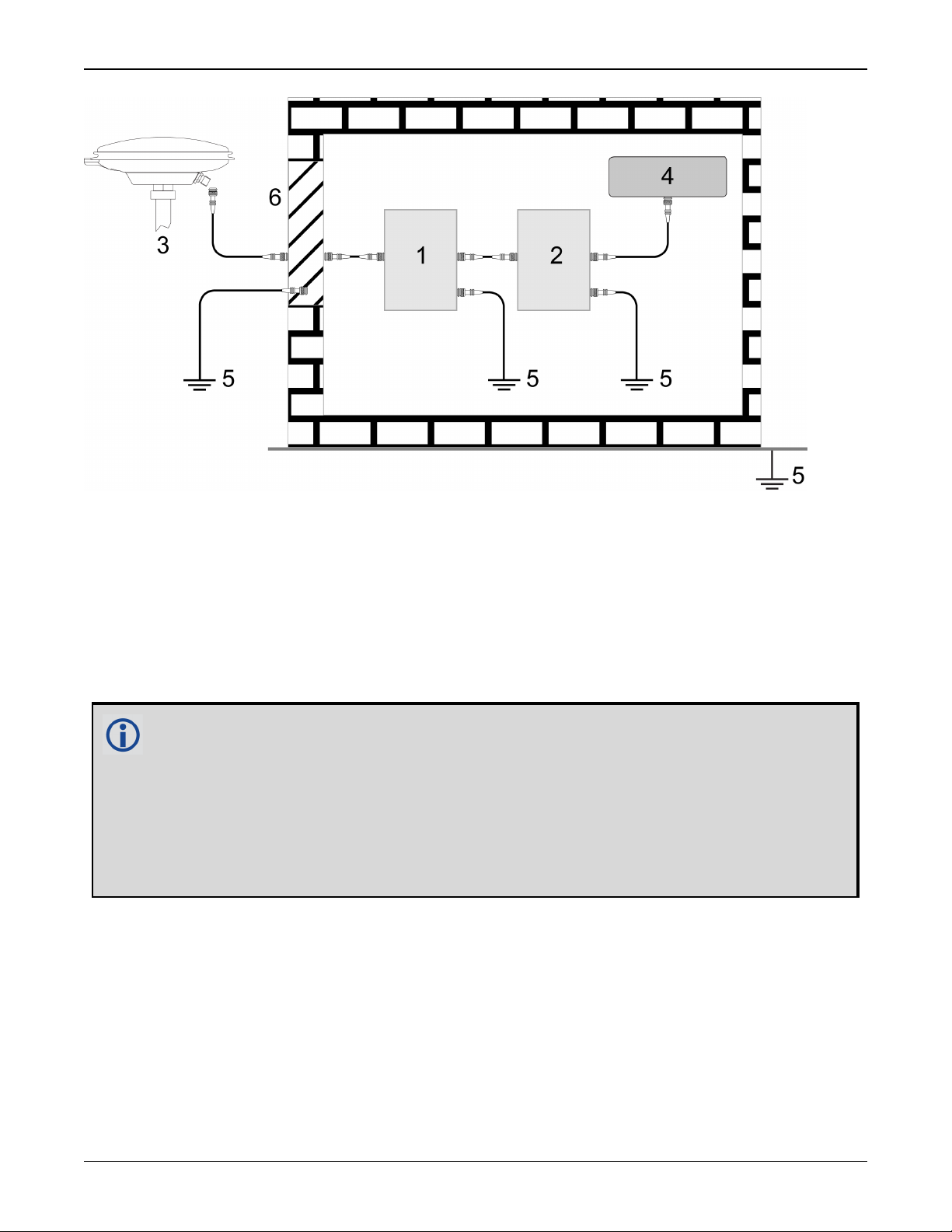
6.
The primary and secondary lightning protections should be as close to the building's entrance
as possible. Where feasible, mount onto the grounding plate itself (refer to the figure
below).
OEM7 SPAN Installation and Operation User Manual v4 18
Notices Receiver Card
Ref# Description
1 Primary lightning protection device
2 Secondary lightning protection device
3 External antenna
4 GNSS Receiver
5 To ground
6 Grounding plate or grounding point at the building’s entrance
Acceptable choices for earth grounds, for central buildings, are:
l
Grounded interior metal cold water pipe within five feet (1.5 m) of the point where
it enters the building
l
Grounded metallic service raceway
l
Grounded electrical service equipment enclosure
l
Eight-foot grounding rod driven into the ground (only if bonded to the central building ground by #6, or heavier, bonding wire)
These installation instructions are the minimum requirements for receiver and antenna installations.
Where applicable, follow the electrical codes for the country of installation. Examples of country
codes include:
l
USA National Electrical Code (NFPA 70)
l
Canada Canadian Electrical Code (CSA C22.1)
l
UK British Standards Institute (BSI 7671)
OEM7 SPAN Installation and Operation User Manual v4 19
Notices Receiver Card
Conventions
The following conventions are used in this manual:
Information that supplements or clarifies text.
A caution that actions, operation or configuration may lead to incorrect or improper use
of the hardware.
A warning that actions, operation or configuration may result in regulatory noncompliance, safety issues or equipment damage.
OEM7 SPAN Installation and Operation User Manual v4 20
Customer Support
NovAtel Knowledge Base
If you have a technical issue, visit the NovAtel Support page at www.novatel.com/support.
Through the Support page, you can contact Customer Support, find papers and tutorials or down-
load current manuals and the latest firmware.
Before Contacting Customer Support
Before you contact NovAtel Customer Support about a software problem, perform the following
steps:
If logging data over an RS-232 serial cable, ensure that the configured baud rate can support the data bandwidth (see SERIALCONFIG command). NovAtel recommends a min-
imum suggested baud rate of 115200 bps.
1.
Log the following data to a file on your computer for 15 minutes:
RXSTATUSB onchanged
RAWEPHEMB onchanged
GLORAWEPHEMB onchanged
BESTPOSB ontime 1
RANGEB ontime 1
RXCONFIGA once
VERSIONA once
For SPAN systems, add the following logs to the above list in the file created on your computer:
RAWIMUSXB onnew
INSUPDATESTATUSB onnew
INSPVAXB ontime 1
INSCONFIGA once
2.
Send the data file to NovAtel Customer Support: support@novatel.com
3.
You can also issue a FRESET command to the receiver to clear any unknown settings.
The FRESET command will erase all user settings. You should know your configuration
(by requesting the RXCONFIGA log) and be able to reconfigure the receiver before you
send the FRESET command.
If you are having a hardware problem, send a list of the troubleshooting steps taken and the results.
Contact Information
Log a support request with NovAtel Customer Support using one of the following methods:
Log a Case and Search Knowledge:
OEM7 SPAN Installation and Operation User Manual v4 21

Customer Support
Website: www.novatel.com/support
Log a Case, Search Knowledge and View Your Case History: (login access required)
Web Portal: https://novatelsupport.force.com/community/login
E-mail:
support@novatel.com
Telephone:
U.S. and Canada:1-800-NOVATEL (1-800-668-2835)
International:+1-403-295-4900
OEM7 SPAN Installation and Operation User Manual v4 22

Chapter 1 OEM7 SPAN Overview
Chapter 1 OEM7 SPAN Overview
NovAtel's Synchronous Position, Attitude and Navigation (SPAN®) technology brings together
two very different but complementary positioning and navigation systems namely Global Navigation Satellite System (GNSS) and an Inertial Navigation System (INS). By combining the best
aspects of GNSS and INS into one system, SPAN technology is able to offer a solution that is
more accurate and reliable than either GNSS or INS could provide alone. The combined
GNSS+INS solution has the advantage of the absolute accuracy available from GNSS and the
continuity of INS through traditionally difficult GNSS conditions.
The SPAN system consists of the following components:
l
NovAtel OEM7 receiver
These receivers are capable of receiving and tracking different combinations of GPS,
GLONASS, Galileo, BeiDou, NavIC and QZSS signals on a maximum of 555 channels. OEM7
receivers can also allocate channels for the reception of correction service signals from
SBAS (standard) and NovAtel Correct™with PPP (optional). OEM7 adaptability offers multisystem, frequency, and size configurations for any application requirement. Patented Pulsed
Aperture Correlator (PAC) technology combined with a powerful microprocessor enable multipath-resistant processing. Excellent acquisition and re-acquisition times allow this receiver
to operate in environments where very high dynamics and frequent interruption of signals
can be expected. The OEM7 receiver also supports the timing requirements of the IMU and
runs the real-time INS filter.
l
IMU
The Inertial Measurement Unit (IMU) consists of three accelerometers and three gyroscopes
(gyros) so that accelerations along specific axes and angular rotations can be measured.
Several IMU types are supported and are listed in Table 2: SPAN-Compatible IMUs on
page25.
l
GNSS antenna
The GNSS receiver is connected to the IMU with an RS-232, RS-422 or SPI link. A NovAtel GNSS
antenna must also be connected to the receiver to track GNSS signals. After the IMU enclosure,
GNSS antenna and appropriate power supplies are attached, and a few simple configuration commands are entered, the SPAN system will be ready to navigate.
1.1 Fundamentals of GNSS+INS
GNSS positioning observes range measurements from orbiting GNSS satellites. From these
observations, the receiver can compute position and velocity with high accuracy. NovAtel GNSS
positioning systems are highly accurate positioning tools. However, GNSS in general has some
restrictions which limit its usefulness in some situations. GNSS positioning requires line of sight
view to at least four satellites simultaneously. If these criteria are met, differential GNSS positioning can be accurate to within a few centimetres. If however, some or all of the satellite signals are blocked, the accuracy of the position reported by GNSS degrades substantially, or may
not be available at all.
In general, an INS uses forces and rotations measured by an IMU to calculate position, velocity
and attitude. This capability is embedded in the firmware of OEM7 receivers. Forces are measured by accelerometers in three perpendicular axes within the IMU and the gyros measure angular rotation rates around those axes. Over short periods of time, inertial navigation gives very
accurate acceleration, velocity and attitude output. The INS must have prior knowledge of its
OEM7 SPAN Installation and Operation User Manual v4 23
Chapter 1 OEM7 SPAN Overview
initial position, initial velocity, initial attitude, Earth rotation rate and gravity field. Since the
IMU measures changes in orientation and acceleration, the INS determines changes in position
and attitude, but initial values for these parameters must be provided from an external source.
Once these parameters are known, an INS is capable of providing an autonomous solution with
no external inputs. However, because of errors in the IMU measurements that accumulate over
time, an inertial-only solution degrades with time unless external updates such as position, velocity or attitude are supplied.
The SPAN system’s combined GNSS+INS solution integrates the raw inertial measurements
with all available GNSS information to provide the optimum solution possible in any situation. By
using the high accuracy GNSS solution, the IMU errors can be modeled and mitigated. Conversely, the continuity and relative accuracy of the INS solution enables faster GNSS signal reacquisition and RTK solution convergence.
The advantages of using SPAN technology are its ability to:
l
Provide a full attitude solution (roll, pitch and azimuth)
l
Provide continuous solution output (in situations when a GNSS-only solution is impossible)
l
Provide faster signal reacquisition and RTK solution resolution (over stand-alone GNSS
because of the tightly integrated GNSS and INS filters)
l
Output high-rate (up to 200 Hz or greater depending on your logging selections) position,
velocity and attitude solutions for high-dynamic applications, see also Logging Restriction
Important Notice on page90
l
Use raw phase observation data (to constrain INS solution drift even when too few satellites
are available for a full GNSS solution)
For more information about GNSS and INS, refer to www.novatel.com/an-introduction-
to-gnss/
1.2 Models and Features
All SPAN system receivers are factory configurable for L1/L2 RTK capability and are compatible
with an IMU. Each model is capable of multiple positioning modes of operation.
The SPAN features enabled on a receiver are identified in the 10thand 11thcharacters of the
OEM7 model string. For example, if the model string is FFNRNNTBNS1, the characters S1
identify the SPAN features. If the 10thand 11thcharacters are not present in the model number,
SPAN has not been enabled on the receiver.
The model string is viewed using the VERSION log.
The SPAN features can also be viewed using the MODELFEATURES log.
The 10thcharacter (S in this example) identifies the INS Options. The 11thcharacter (1 in this
example) identifies the IMU grade.
1.2.1 INS Options
The INS Model character indicates which features are enabled by the model. The INS options are
explained in Table 1: INS Options on the next page.
OEM7 SPAN Installation and Operation User Manual v4 24

Chapter 1 OEM7 SPAN Overview
Table 1: INS Options
INS
Model
S
P
R
Meaning Description
SPAN
Enabled
Enhanced
Profiles
Relative
INS
1.2.2 IMU Grade
Standard SPAN functionality.
This model enables most SPAN functionality.
Allows the use of enhanced INS profiles for certain
applications. For example, dead reckoning performance is
controlled using the LAND_PLUS INS Profile and Heave filter
output is controlled using the MARINE_PLUS INS Profile.
For information about INSProfiles, see INS Profiles on
page77. For information about enabling and disabling
INSProfiles, see the SETINSPROFILE command.
Heave filter output is also controlled under this option.
Allows for two SPAN systems to communicate and produce a
relative solution (position, velocity, attitude) between them.
This option also inherits the enhanced profile functionality of
the P model. For more information, see Relative INS on
page105
Functionality
Inheritance
S
S+P
S+P+R
The IMU grade indicates which classes of IMUs are supported by the model. The IMU grade is
specified as a number between 1 and 3 to indicate the IMU grade available to the model.
So, for example, to use an ISA-100C IMU, an IMU grade of 3 is required. A larger number also
allows use of any IMU in a lower grade. So the S3 model required for the ISA-100C would also
allow the use of any IMU in grades 1 and 2.
Table 2: SPAN-Compatible IMUs below shows the IMU grade classification.
Table 2: SPAN-Compatible IMUs
Supported IMUs
IMU Grade NovAtel Part Name IMU Name
IMU-CPT KVH CPT IMU
IMU-H1930-CA50 Honeywell HG1930-CA50
IMU-IGM-A1 IMU-IGM-A1
1
IMU-IGM-S1 IMU-IGM-S1
OEM-IMU-ADIS-16488 Analog Devices ADIS16488
OEM-IMU-EG320N Epson G320N
OEM-IMU-STIM300 Sensonor STIM300
OEM7 SPAN Installation and Operation User Manual v4 25

Chapter 1 OEM7 SPAN Overview
IMU Grade NovAtel Part Name IMU Name
Supported IMUs
IMU-H1900-CA50 Honeywell HG1900-CA50
IMU-H58 Honeywell HG1700-AG58
IMU-H62 Honeywell HG1700-AG62
2
3
IMU-KVH1750 KVH 1750 IMU
IMU-µIMU Lifef µIMU-IC
UIMU-H58 Honeywell HG1700-AG58
UIMU-H62 Honey well HG1700-AG62
IMU-FSAS-EI IMAR iIMU-FSAS
IMU-ISA-100C Litef ISA-100C
IMU-LN200 Northrop Grumman LN-200-L
OEM-IMU-ISA-100C Litef ISA-100C
1.3 Related Documents and Information
This manual contains sufficient information about the installation and operation of the SPAN system. It is beyond the scope of this manual to provide details on service or repair. Contact your
local NovAtel dealer for any customer service related inquiries, see Customer Support on
page21.
The OEM7 receiver utilizes a comprehensive user-interface command structure, which requires
communications through its communications ports. For descriptions of the commands and logs
available with OEM7 receivers, refer to the OEM7 Commands and Logs Reference Manual avail-
able on the NovAtel website at www.novatel.com/support/. It is recommended that these doc-
uments be kept together for easy reference.
For more information about the OEM7 receivers, refer to the OEM7 Installation and Operation
User Manual or PwrPak7 Installation and Operation User Manual.
SPAN system output is compatible with post-processing software from NovAtel's Waypoint
Products Group. Visit our web site at www.novatel.com for details.
OEM7 SPAN Installation and Operation User Manual v4 26
®
Chapter 2 SPAN Installation
Chapter 2 SPAN Installation
A SPAN system consists of an OEM7 receiver, an IMU, a GNSS antenna, power and a communication link (if your application requires real time differential operation). The installation process varies based on the OEM7 receiver.
l
OEM7 Receiver Card Installation below
l
PwrPak7 Installation on page61
l
PwrPak7-E1 Installation on page64
If your IMU enclosure and IMU were supplied separately, additional instructions for
installing the IMU into an the enclosure are available in the following appendices:
HG1700 IMU in Universal Enclosure on page254, LN-200 IMU in Universal
Enclosure on page264, HG1700 IMU in SPAN HG Enclosure on page271 and LN-200
IMU in SPAN IMU Enclosure on page278.
2.1 OEM7 Receiver Card Installation
The following diagram shows a typical SPAN installation using an OEM7 receiver card and an
IMU in an enclosure.
OEM7 SPAN Installation and Operation User Manual v4 27
Chapter 2 SPAN Installation
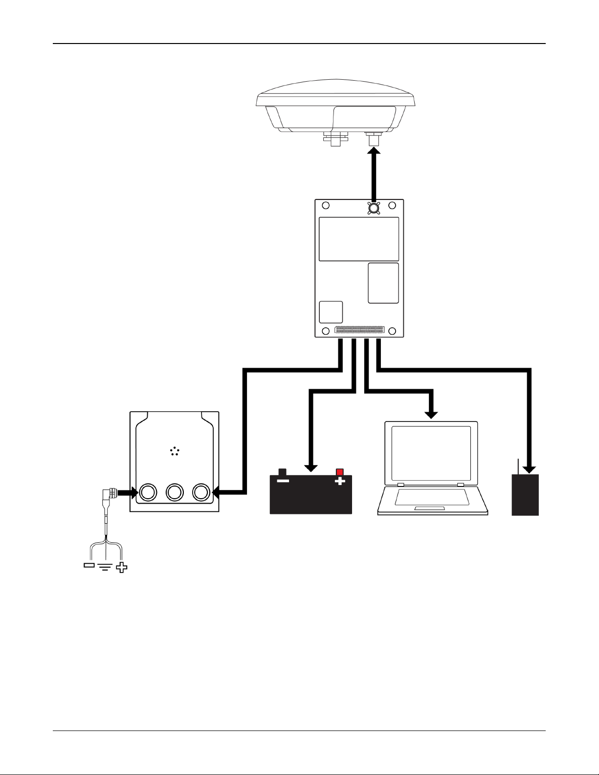
Figure 1: Typical Installation of a SPAN System with an OEM7 Receiver Card
Complete the following steps to set up your NovAtel SPAN system.
1.
Mount the GNSS antenna.
See Mounting the GNSS Antenna on page30 for details.
2.
Mount the IMU.
See Mount the IMU on page30 for details.
3.
Install the OEM7 receiver card.
OEM7 SPAN Installation and Operation User Manual v4 28

Chapter 2 SPAN Installation
See the OEM7 Installation and Operation User Manual for information about installing an
OEM7 receiver.
4.
Connect the GNSS antenna to the OEM7 receiver card.
See the OEM7 Installation and Operation User Manual for information about installing an
OEM7 receiver.
5.
Connect the IMU to the OEM7 receiver.
See Connect the IMU to the OEM7 Receiver Card on page32 for details.
6.
Connect the I/O strobe signals (optional).
See the OEM7 Installation and Operation User Manual for information about installing an
OEM7 receiver.
7.
Connect power to the IMU and receiver.
See Connect Power on page44 for details.
8.
Connect a data communication device, such a computer, to the receiver. A data communication device is used to configure and monitor the receiver.
See the OEM7 Installation and Operation User Manual for information about installing an
OEM7 receiver.
2.1.1 Selecting a GNSS Antenna
NovAtel offers a variety of GNSS antennas, including single, dual and triple-frequency, tripleband and wide-band reference antennas (refer to our web site: www.novatel.com/antennas for
details of available antennas). All antennas include band pass filtering and an LNA. The GNSS
antenna chosen depends on the particular application. Each model offers exceptional phase center stability and a significant measure of immunity against multipath interference. Each antenna
has an environmentally sealed radome and all meet the European Union’s Restriction of Hazardous Substances (RoHS) and Waste Electrical and Electronic Equipment (WEEE).
If a non-NovAtel GNSS antenna is chosen, a typical antenna LNA gain between 26 dB to 30 dB is
recommended in a rover station application.
For more information about antenna selection, see Importance of Antenna Selection on
page287.
2.1.2 Choosing a Coaxial Cable
An appropriate coaxial cable matches the impedances of the antenna and receiver (50 ohms)
and has a line loss not exceeding 10.0 dB. If the limit is exceeded, excessive signal degradation
may occur and the receiver may not meet performance specifications. NovAtel offers several
coaxial cables to meet GNSS antenna interconnection requirements, including:
l
5, 15 and 30 m antenna cable with TNC connectors on both ends (NovAtel part numbers GPSC006, GPS-C016 and GPS-C032)
For more information about antenna cabling, including using cables longer than 30 m
and in-line amplifiers, refer to APN-077: RF Equipment Selection and Installation available from (www.novatel.com/assets/Documents/Bulletins/APN-077-RFEquip-
mentSelection.pdf).
OEM7 SPAN Installation and Operation User Manual v4 29
Chapter 2 SPAN Installation
A conversion is required between the MMCX, MMBX or MCX connector on the OEM7
receiver card and the female TNC connector on NovAtel’s GNSS antennas.
NovAtel recommends using high quality coaxial cables because an impedance
mismatch is possible when using lower quality cables and this produces reflections
in the cable that increases signal loss. Although other high quality antenna cables
can be used, the performance specifications of the OEM7 receivers are warranted
only when used with NovAtel supplied accessories.
2.1.3 Mounting the GNSS Antenna
The OEM7 receiver is designed to operate with any NovAtel GNSS antenna.
When installing the antenna:
l
Choose an antenna location with a clear view of the sky so each satellite above the horizon
can be tracked without obstruction. For more information on RF signal propagation and multipath, refer to the NovAtel application note APN-008 Discussions on RF Signal Propagation
and Multipath at www.novatel.com/support/.
l
Mount the antenna on a secure, stable structure capable of safe operation in the specific
environment.
l
Ensure the antenna cannot move due to dynamics.
Antenna LNA Power
NovAtel antennas and coaxial cables meet receiver RF input gain requirements. NovAtel coaxial
cables are designed to introduce no more than 10 dB loss and NovAtel antennas are equipped
with built-in LNAs that provide 29 dB of gain to the satellite signal received.
The power to the antenna LNA is provided through the receiver’s RF port center conductor.
OEM7 receivers provide +5 VDC ±5% at a maximum of 200 mA.
Antenna supply over current protection limits the LNA power.
If a short circuit or other problem causes an overload of the current supplied to the
antenna, the receiver hardware shuts down the power supplied to the antenna. To
restore power, power cycle the receiver. The Receiver Status word, available in the
RXSTATUS log (see OEM7 Commands and Logs Reference Manual), provides more
information about the cause of the problem.
2.1.4 Mount the IMU
Mount the IMU in a fixed location where the distance from the IMU to the GNSS antenna phase
center is constant. Ensure that the orientation with respect to the vehicle and antenna is also constant.
For attitude output to be meaningful, the IMU should be mounted such that the positive Z-axis
marked on the IMU enclosure points up and the Y-axis points forward through the front of the
vehicle, in the direction of track. If the IMU is not mounted in this orientation, a rotational offset
must applied. See Rotational Offsets on page75 for more information.
OEM7 SPAN Installation and Operation User Manual v4 30
 Loading...