

Novatel OEM7, OEM7700, OEM7720, OEM7600, OEM729 Series Manual
...
OEM7
DEVELOPMENT KIT GUIDE
GM-14915145 Rev 3 October 2019
The OEM7 Development Kit (Dev Kit) provides a convenient way to access
OEM7® input and output signals. The Dev Kit alone is used with NovAtel’s
OEM7700 and OEM7720 receiver cards. To use the Dev Kit with NovAtel’s
OEM719, OEM729 or OEM7600 receiver cards, an optional Interposer
Card Kit is required.
Box Contents
The following is provided with your OEM7 Development Kit:
• OEM7 Development Board (NovAtel Part #01019417)
• One BNC-MMCX cable assembly (NovAtel Part #01019431)
• Two TNC-MMBX cable assemblies (NovAtel Part #01019599)
• Dev Kit power cable assembly (NovAtel Part #01019538)
• 2 m USB cable type A to micro B (NovAtel Part #60723119)
• 1.8 m null modem cable (NovAtel Part #01017658), DB-9 female/female
to connect to COMs 1, 2 or 3.
• Four adhesive rubber feet (NovAtel Part #28325059)
• Four M3x0.5x10 mm standos (NovAtel Part #28423237)
• Four M3x0.5x6 mm Philips screws (NovAtel Part #35000306)
• Two 3 mm spacers (NovAtel Part #28423235)
• Two M2x8 socket head caps (NovAtel Part #28523067)
Optional Interposer Card Content
• OEM7 Interposer board (NovAtel Part #01019416) for use with
(OEM729R, OEM729 and OEM719 receiver cards)
• One TNC-MCX cable assembly (NovAtel Part #01019429)
• One TNC-MMCX cable assembly (NovAtel Part #01019430)
• Four M3x0.5x14 mm standos (NovAtel Part #28423059)
• Five M3x0.5x10 mm standos (NovAtel Part #28423237)
• Six M3x0.5x12 mm standos (NovAtel Part #28423222)
• Four M3x0.5x8 mm standos (NovAtel Part #28423231)
• Five M3x0.5x6 mm Philips screw (NovAtel Part #35000306)
Optional OEM7600 Interposer Card Content
• OEM7600 Interposer Board (NovAtel Part #01020246)
• Six M3x0.5x10 mm standos (NovAtel Part #28423237)
• Ten M3x0.5x4 mm Philips screws (NovAtel Part #35023107)
Additional Equipment Required
Depending on the application, some or all of the following will be required:
• OEM7 series receiver card
• A Microsoft® Windows®-based computing device with a RS-232 DB-9,
USB port or 10/100BASE-T port
• A +9 VDC to 36 VDC power supply, capable of supplying at least 10 W
• A quality antenna, such as NovAtel’s GNSS-500 or GNSS-800 Series.
• A 50 ohm coaxial cable with a male TNC connector at the Dev Kit end,
for connecting to the GNSS antenna.
(Two if using an OEM7720 and two GNSS antennas.)
• If necessary, a 50 ohm coaxial cable with a male BNC connector at the
Dev Kit end for connecting to an EXT OSC port (refer to External Oscil-
lator and Mounting the Coaxial Cable in the Bracket sections on the
other side of this sheet)
• If necessary, an RS-422 cable (COM1 or COM2) and CAN1 or CAN2
connection
• An RJ-45 Ethernet cable
Questions or Comments
Contact NovAtel Customer Support to obtain copies of the Dev Kit
BOM, schematics and assembly drawings. The OEM7 Dev Kit is
not intended to be used as a reference design for implementation
in end applications. Original component manufacturer design
recommendations should be sought before incorporating any
components used on the Dev Kit into an end application design.
If you have any questions or comments regarding your OEM7
Development Kit, contact NovAtel using one of these methods:
Email: support@novatel.com
Web: www.novatel.com
Phone: 1-800-NOVATEL (U.S. & Canada)
403-295-4500 (International)
NovAtel and OEM7 are registered trademarks of NovAtel Inc.
OEM719, OEM729, OEM7600, OEM7700 and OEM7720 are
trademarks of NovAtel Inc.
All other trademarks are the property of their respective owners.
Content subject to change without notice.
OEM7 Development Kit
©Copyright 2019 NovAtel Inc. All rights reserved.
Printed in Canada on recycled paper. Recyclable.
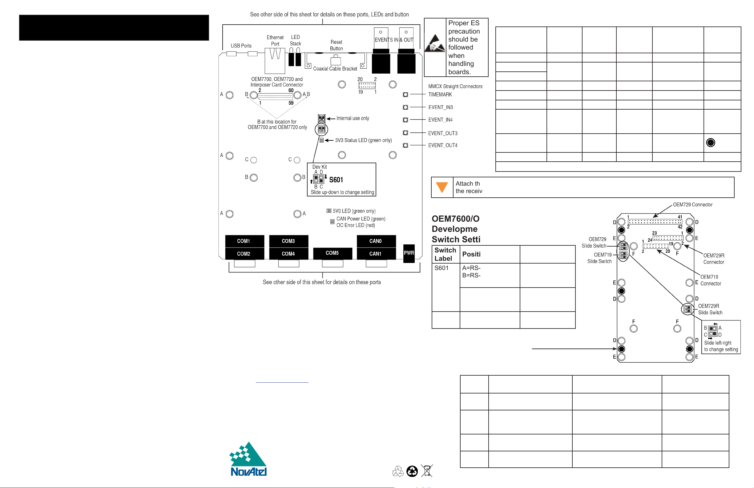
Proper ESD
Hardware Use
precautions
should be
OEM Card Size
followed
when
handling
boards.
Interposer Board 10 mm 5 28423237 Dev Board A
OEM7720
OEM7700
OEM7600 M3 screws 4 35023107 Interposer Board N/A
OEM729 14 mm 4 28423059 Interposer Board D
OEM729R 12 mm 4 28423222 Interposer Board E
OEM719
OEM719A
OEM719B
Interposer Board
to Dev Board
IMU (future use) 6 mm 4 28423223 Dev Board Future use
10 mm 4 28423237 Dev Board B
8 mm 4 28423231 Interposer Board F
M3 screws 5 35000306
Insert standos into appropriate holes for card(s) used. Secure using screws.
Attach the MCX, MMCX or MMBX connector of the coaxial cable(s) to the receiver BEFORE securing
the receiver cards to the Dev Board with the standos and screws.
OEM7600/OEM7700/OEM7720
Development Board
Switch Settings
Switch
Label
S601 A=RS-422
S301 C: 3V3=3V3,
Position Function
Select COM1 and
B=RS-232
C=COM5 TXD/RXD
D=COM2 CTS/RTS
Default = C
COM2 RS-232 or
RS-422 mode
Either activate
COM5 or enable
COM2 ow control
Internal use only
OEM719/OEM729
Optional Interposer Card
Switch Settings
Switch
Label
S101 729 COM1 RS-422/232
S201 719 CAN MUX (U301) n/a B=CAN0
S301 729 COM3 MUX (U303) A=GPIO & EVENT_IN2
S301 719 COM3/USB MUX
Signal OEM729 OEM719
(U201)
(U304, U302)
#
Included
D=729 COM1 in RS-422 mode
C=729 COM1 in RS-232 mode
B=COM3
n/a C=COM3
NovAtel
Stando
Part #
Connect Card
to...
n/a
A=EVENT_OUT2 &
EVENT_IN2
n/a
D=USB & EVENT_IN1
Stando
Insertion
Position
9 V to 36 V
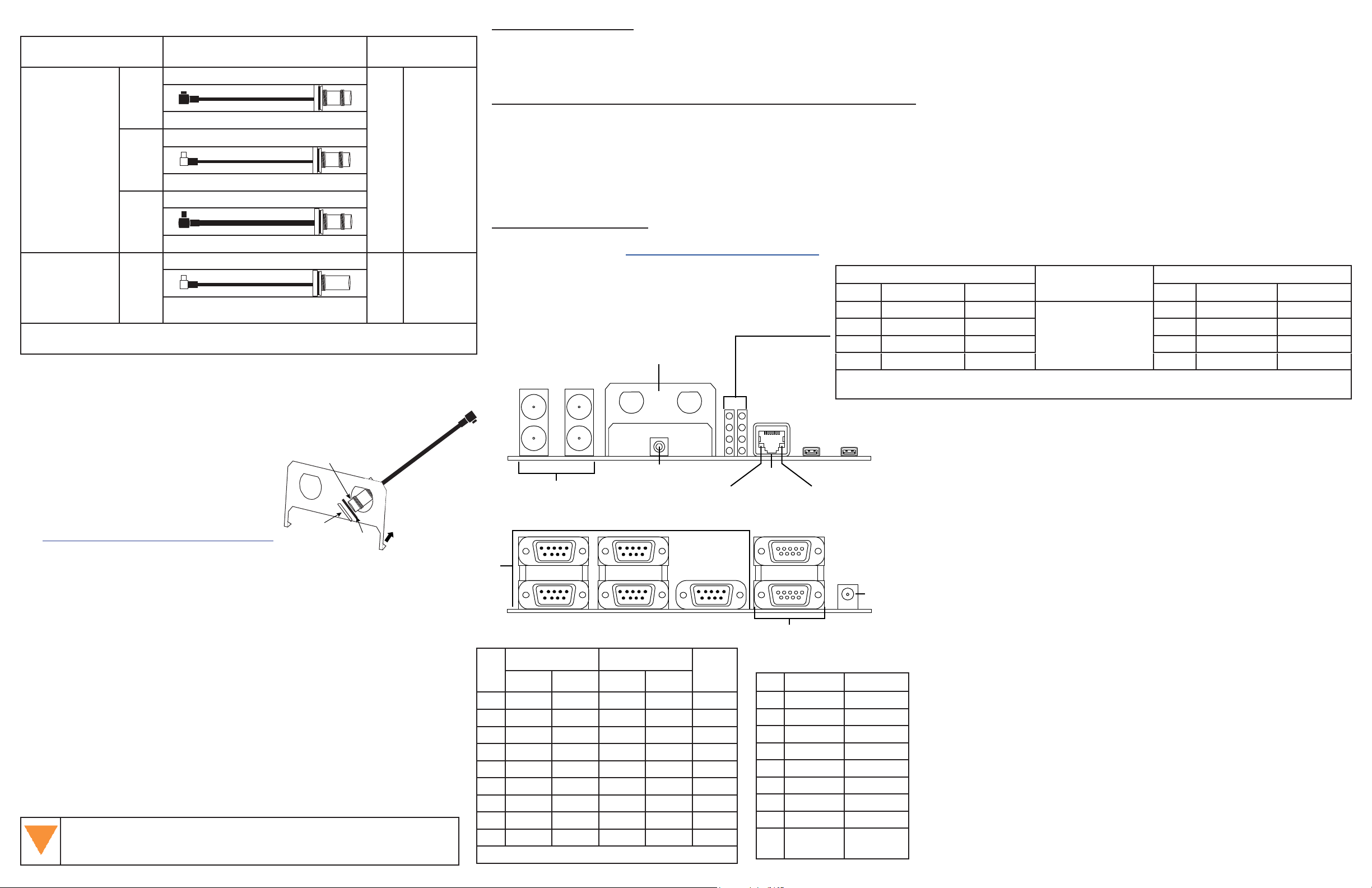
Coaxial Cable Assembly (for ANT/OSC/EVENTS)
Connect this end as indicated below
OEM719/OEM719A
MCX
#01019429
Attach to
Antenna port of
receiver card
Attach to External Oscillator on
receiver card or
Event lines on
Dev Board
Always connect the coaxial cable to the receiver card prior to attaching to the Dev Board
or Interposer card.
MMCX
MMBX
MMCX
OEM729/OEM729R/OEM7600
#01019430
OEM719B/OEM7700/OEM7720
#01019599
OEM729/OEM729R/Dev Board
#01019431
External Oscillator
Some applications require greater precision
than that possible with the OEM7 VCTCXO,
in which case you may need to connect the
Coaxial Cable Bracket
Mounted on Dev Board
OEM7 to an external high-stability oscillator,
which may run at either 5 MHz or 10 MHz.
TNC/BNC cable end
Antenna Selection
Select a quality GNSS antenna, such as one
from NovAtel’s 500 or 800 series. Contact
your NovAtel representative or visit our web
site www.novatel.com/products/gnss-antennas
Nut
for a full range of available antenna options.
Connect this end as
indicated below
TNC
BNC
Washer
GNSS
Antenna
OSC
(External
Oscillator)
EVENTS
Dev Board
Mounting the Coaxial Cable into Bracket
The bracket openings are used to mount and secure the Antenna (ANT) and/or
External Oscillator (OSC) connectors to the Development Board.
1. Remove the top nut and washer from the TNC/BNC end of the coaxial cable.
Set aside.
2. Thread the TNC or BNC end of coaxial cable through the bracket from Dev
Board side to the outside (either opening).
3. Slide the washer and then the nut over the TNC or BNC end of the protrud-
ing coaxial cable and slide up against the external side of the bracket.
4. Hand tighten nut to secure the cable and connector to the bracket.
5. Connect antenna to receiver card or EVENT to the Dev Board.
6. Continue to Installation & Powering Steps section or repeat as needed for
second cable.
Attach the MCX, MMCX or MMBX connector of the coaxial cable(s)
to the receiver BEFORE securing the receiver cards to the Dev Board
with the standos and screws.
Warnings and Restrictions
For evaluation only, in Laboratory/Development Environments. The development kit is not nished electrical and electronic equipment (EEE) and is not intended for
consumer use. It is intended solely for use for preliminary evaluation in laboratory/development environments by technically qualied experts who are familiar with the dangers and application risks associated with handling electrical mechanical components, systems, and subsystems. The development kit should not be used as all or part of a
nished end product.
Federal Communications Commission (FCC) and Industry Canada (IC) Notices:
This development kit is designed to allow:
(1) Product developers to evaluate electronic components, circuitry, or software associated with the kit to determine whether to incorporate such items in a nished product
and
(2) Software developers to write software applications for use with the end product. This kit is not a nished product and when assembled may not be resold or otherwise
marketed unless all required FCC and IC equipment authorizations are rst obtained. Operation is subject to the condition that this product not cause harmful interference to
licensed radio stations and that this product accept harmful interference.
(3) This kit generates, uses, and can radiate energy and has not been tested for compliance with the limits of digital devices pursuant to Part 15 of FCC or ICES-003 rules
which are designed to provide reasonable protection against radio frequency interference.
EU Declaration of Conformity
Hereby, NovAtel Inc. declares that the OEM7 Development Kit is in compliance with Directive 2011/65/EU. The full text of the EU declaration of conformity is available at the
following Internet address: www.novatel.com/products/compliance.
Coaxial Cable Bracket
ANT TNC / EXT OSC BNC
IN1 IN2
OUT2OUT1
EVENT Ports
2 Position, 50 Ohm BNC
1 GHz Max
1
COM Ports
DB9, Male
PIN
1 NC NC NC NC NC
2 RXD1 RX1+ RXD2 RX2+ RXD
3 TXD1 TX1+ TXD2 TX2+ TXD
4 NC NC NC NC NC
5 GND GND GND GND GND
6 NC NC NC NC NC
7 RTS1 TX1- RTS2 TX2- NC
8 CTS1 RX1- CTS2 RX2- NC
9 NC NC NC NC NC
1
COM2 RTS/CTS MUX with COM5 TXD/RXD
6
COM1
COM2
COM1 COM2
RS-232 RS-422 RS-232 RS-422
5 15
9 69
Reset Button
Press to perform
reset of card
COM3
COM4 COM5
1
6
4
2
0
Yellow LED
Not used
COM3,
COM4,
COM5
Status LED States
LED Stack
7
5
3
1
Ethernet
RJ45
10/100 Base-T
CAN0
CAN1
CAN Ports
DB9, Female
PIN CAN0 CAN1
1 NC NC
2 CAN_L CAN_L
3 GND GND
4 NC NC
5 GND GND
6 GND GND
7 CAN_H CAN_H
8 NC NC
9 12 V CAN
power
USB
Micro-AB
USB1
Green LED
Link/Activity
Left LED Stack from Top Right LED Stack from Top
LED# Description Color LED# Description Color
6 n/a 7 n/a
4 Status GREEN* 5 ME_RDY GREEN
2 Status RED* 3 POS_VALID GREEN
0 ERROR RED 1 POWER RED
* LED 2 and 4 represents the receiver card’s onboard LED status (when on at the same time, they represent the
yellow error status code). Search for Status Indicator in the OEM7 online documentation.
Installation & Powering Steps
1. Flip the Dev Board upside down. Attach the four provided rubber feet over
the four white circles in each corner of the Dev Board. These provide stability for the board.
USB0
DC Power
12 V CAN
power
2. Turn the Dev Board right side up and place on a at stable surface.
3. Ensure the steps listed in the Mounting the Coaxial Cable into Bracket
section are complete before progressing to Step 4.
4. If using, make the connections/attachments for the ANT/OSC cables using
the TNC/BNC end of the coaxial cable and connect to receiver card or Dev
Board as indicated in Coaxial Cable Assembly table.
5. If needed, attach the Interposer card to the Dev Board using the provided
standos and screws as indicated in the Stando Use table on the other
side of this sheet.
For the OEM7600, attach the OEM7600 to the OEM7600 Interposer board
using M3 screws before attaching the Interposer Board to the Dev Board.
6. If required, attach the applicable receiver card to the Interposer card using
the provided standos and screws OR
Attach applicable receiver card directly to the Dev Board using the provided
standos and screws as indicated in the Stando Use table on the other
side of this sheet.
7. If using, connect EVENT end cable to applicable EVENT connector on the
Dev Board. Refer to the Coaxial Cable Assembly table on this page. For
event connector locations, refer to the illustration on the other side of this
sheet.
8. Set external power supply to 9 V to 36 VDC.
9. Set any Slide Switches on the Dev Board and, if using, the Interposer card.
Refer to the Switch Settings tables on the other side of this sheet.
10. Connect any communications equipment to be used.
11. Connect the power cord and plug into external power supply.
 Loading...