

Novatel OEM7 Installation And Operation User Manual

OEM7
®
Installation and Operation
User Manual
OM-20000168 v1 February 2017

OEM7®Installation and OperationUser Manual
OEM7 Installation and Operation User Manual
Publication Number: OM-20000168
Revision Level: v1
Revision Date: February 2017
Firmware Version: 7.200 / OM7MR0200RN0000
To download the latest firmware and/or software visit: www.novatel.com/support/firmware-
downloads.
Warranty
NovAtel Inc. warrants that its GNSS products are free from defects in materials and workmanship, subject to the conditions set forth on our web site: www.nova-
tel.com/products/warranty/ and for the following time periods:
OEM7®Receivers One (1) Year
GNSS Antenna Series One (1) Year
Cables and Accessories Ninety (90) Days
Software Warranty One (1) Year
Return Instructions
To return products, refer to the instructions found at: www.novatel.com/warranty-return.
Proprietary Notice
Information in this document is subject to change without notice and does not represent a commitment on the part of NovAtel Inc. The software described in this document is furnished under
a licence agreement or non-disclosure agreement. The software may be used or copied only in
accordance with the terms of the agreement. It is against the law to copy the software on any
medium except as specifically allowed in the license or non-disclosure agreement.
The information contained within this manual is believed to be true and correct at the time of
publication.
ALIGN, SPAN, STEADYLINE and NovAtel are registered trademarks of NovAtel Inc.
OEM7, OEM719, OEM729, OEM7700, GLIDE, NovAtel CORRECT, RTK ASSIST and NovAtel Connect
are trademarks of NovAtel Inc.
All other brand names are trademarks of their respective holders.
© Copyright 2017 NovAtel Inc. All rights reserved.
Unpublished rights reserved under International copyright laws.
OEM7 Installation and Operation User Manual v1 2

OEM7®Installation and OperationUser Manual
Table of Contents
OEM7®Installation and OperationUser Manual
OEM7 Installation and Operation User Manual 2
Warranty 2
Return Instructions 2
Proprietary Notice 2
Notices
FCC 8
Industry Canada 8
European Union (EU) 8
WEEE 8
RoHS 9
REACH 9
Ethernet Port 9
Lightning Protection Installation and Grounding Procedure 9
Conventions 11
Customer Support
NovAtel Knowledge Base 12
Before Contacting Customer Support 12
Contact Information 12
Chapter 1 Introduction
1.1 Related Documents and Information 14
1.2 OEM7 Receiver System Overview 14
1.2.1 OEM7 Family Card 15
1.2.2 Enclosure 15
1.2.3 GNSS Antenna 15
1.2.4 Power Supply 15
1.2.5 Optional External Frequency Reference 16
1.2.6 Data Communications Equipment 16
1.2.7 OEM719 Receiver Overview 16
1.2.8 OEM729 Receiver Overview 16
1.2.9 OEM7700 Receiver Overview 17
Chapter 2 Installation of OEM7 Family Receiver Cards
2.1 Shipping Box 19
2.2 Additional Equipment Required 19
2.3 Selecting a GNSS Antenna 19
2.4 Choosing a Coaxial Cable 20
2.5 Power Supply Requirements for Receiver Cards 20
2.6 Card Installation Overview 21
2.6.1 Electrostatic Discharge (ESD) Precautions 21
2.7 Mounting the Printed Circuit Board 21
2.7.1 Planning the Mount Location 22
2.7.2 Board to Board Spacing 22
2.7.3 Mounting Options 23
2.7.4 Thermal dissipation 27
2.7.5 Vibration 27
OEM7 Installation and Operation User Manual v1 3

OEM7®Installation and OperationUser Manual
2.8 Preparing the Data, Signal and Power Interface 27
2.9 Mounting the GNSS Antenna 31
2.10 Connecting the Antenna to the Receiver Card 32
2.10.1 Antenna LNA Power 32
2.11 Applying Power to the Receiver Card 33
2.12 Connecting Data Communications Equipment 33
2.12.1 Serial Ports 33
OEM719Multiplexed Port 34
OEM729 RS-422 Port 35
OEM729 Multiplexed Port 35
OEM7700 Multiplexed Port 36
2.12.2 USB Ports 36
2.12.3 Ethernet Ports 38
2.12.4 SPI Ports 38
2.13 Test that the Receiver is Working 39
2.14 Installing NovAtel PC Utilities 39
Chapter 3 OEM7 Receiver Operation
3.1 Communications with the Receiver 41
3.1.1 Serial Ports 41
3.1.2 Communicating using a Remote Terminal 42
3.1.3 Communicating using a Computer 43
3.2 Getting Started 43
3.2.1 Starting the Receiver 43
3.2.2 Communicating with the Receiver 43
3.3 Transmitting and Receiving Corrections 45
3.3.1 Base Station Configuration 46
3.3.2 Rover Station Configuration 47
3.4 Configuration Notes 47
3.5 ALIGN Heading Master and Remote Configurations 48
3.5.1 Automatic Set Up for Direct-Wire Connection between Master and Rover via
COM2 48
3.5.2 Manual Set Up via COM2 48
3.6 GLIDE 49
3.6.1 Dual-Frequency GLIDE 49
3.6.2 PDP and GLIDE Configurations 49
3.7 STEADYLINE® 50
3.7.1 Maintain 50
3.7.2 Transition 51
3.7.3 Prefer Accuracy 51
3.7.4 UAL 52
3.8 Enabling SBAS Positioning 53
3.9 Enabling NovAtel CORRECT with PPP 53
3.9.1 TerraStar Subscriptions 54
3.9.2 Veripos Subscriptions 55
3.10 RTK ASSIST 55
3.11 Transferring Time Between Receivers 56
3.11.1 GPS to Receiver Time Synchronization 56
3.11.2 Time Definitions 56
3.11.3 Procedures to Transfer Time 57
3.12 Interference Toolkit 61
3.12.1 Monitoring GNSS Signals 61
Example: 61
OEM7 Installation and Operation User Manual v1 4

OEM7®Installation and OperationUser Manual
3.12.2 Monitoring Signals Using a Command Line 61
Example: 62
Example: 62
3.12.3 Monitoring Signals Using NovAtel CONECT 2.0 64
3.12.4 Configure Filters 66
3.12.5 Remove Interference Signals 66
3.13 Logging and Retrieving Data Overview 69
3.14 Additional Features and Information 69
3.14.1 Strobes 69
3.14.2 Status Indicator 69
3.14.3 External Oscillator 70
Chapter 4 Built-In Status Tests
4.1 Receiver Status Word 71
4.2 Error Strobe Signal 72
4.3 RXSTATUSEVENT Log 72
4.4 RXSTATUS Log 72
4.4.1 Status Word 72
4.4.2 Error Word 73
4.4.3 Status Code Arrays 74
4.4.4 Receiver Status Code 74
4.4.5 Auxiliary Status Codes 74
4.4.6 Set and Clear Mask for all Status Code Arrays 75
4.5 Status LED 75
Chapter 5 Ethernet Configuration
5.1 Required Hardware 77
5.2 Static IP Address Configuration 77
5.2.1 Static IP Address Configuration—Receiver 78
5.2.2 Static IP Address Configuration—Windows 7 79
5.2.3 Confirming Ethernet Setup 80
5.3 Dynamic IP Address Configuration 80
5.4 Base/Rover Configuration through Ethernet Connectivity 82
5.5 Large COM Port Data Throughput 83
5.6 NTRIP Configuration 84
Chapter 6 CAN Bus
6.1 Default Configuration 87
6.2 Configuring the CAN Bus 87
6.2.1 Configuration Notes 88
6.2.2 Example of Enabling the CAN Bus 88
6.2.3 Example of Modifying the CAN Bus Parameters 88
6.2.4 Example of Detecting an Address Claim Failure and Reconfiguring 88
6.2.5 Address Claim Procedure 89
6.3 NMEA2000 Logging 89
6.3.1 Example of NMEA2000 Log Configuration 90
6.3.2 Example of Custom PGN Configuration 90
6.4 Corrections Over CAN 90
6.4.1 Example for Receiving Corrections from Any Source 91
6.4.2 Example for Transmitting Corrections to 0x1C Node 91
6.5 NovAtel Messages Over CAN 91
6.6 Configuring OEM7 Receivers to Use OEM6 CAN Settings 92
OEM7 Installation and Operation User Manual v1 5

OEM7®Installation and OperationUser Manual
6.6.1 Configuration on OEM6 92
6.6.2 Configuration on OEM7 92
Chapter 7 Troubleshooting
7.1 Examining the RXSTATUS Log 94
7.2 Examining the AUX1 Status Word 97
7.3 Safe Mode 98
7.3.1 Reset Loop Detection 98
7.3.2 Recovery Steps 98
Chapter 8 NovAtel Firmware and Software
8.1 Firmware Updates and Model Upgrades 99
8.1.1 Firmware Updates 99
8.1.2 Model Upgrades 99
8.2 Authorization Code 100
8.3 Updating or Upgrading Using the WinLoad Utility 101
8.3.1 Transferring Firmware Files 101
8.3.2 Using the WinLoad Utility 101
8.4 Updating Using SoftLoad Commands 103
8.4.1 SoftLoad Commands and Logs 103
8.4.2 Working With S-Records 104
8.4.3 Sending Firmware Data 105
8.4.4 SoftLoad Update Method 106
8.4.5 SoftLoad Errors 108
8.5 Upgrading Using the AUTH Command 109
8.5.1 Upgrade Procedure 109
APPENDIX A OEM719 Technical Specifications
A.1 OEM719 Performance Specifications 111
A.2 OEM719 Mechanical Specifications 113
A.3 OEM719 Electrical and Environmental Specifications 120
A.4 OEM719 Data Communication Specifications 122
A.5 OEM719 Strobe Specifications 124
A.6 OEM719 Interface Connector 126
A.6.1 P1701 Main Connector 20-Pin Header 126
APPENDIX B OEM729 Technical Specifications
B.1 OEM729 Performance Specifications 131
B.2 OEM729 Mechanical Specifications 133
B.3 OEM729 Electrical and Environmental Specifications 136
B.4 OEM729 Data Communication Specifications 138
B.5 OEM729 Strobe Specifications 140
B.6 OEM729 Interface Connectors 142
B.6.1 P1802 Main Connector 24-Pin Header 142
B.6.2 P1803 Expansion Connector 16-Pin Header 147
APPENDIX C OEM7700 Technical Specifications
C.1 OEM7700 Performance Specifications 151
C.2 OEM7700 Mechanical Specifications 153
C.3 OEM7700 Electrical and Environmental Specifications 156
C.4 OEM7700 Data Communication Specifications 158
C.5 OEM7700 Strobe Specifications 160
OEM7 Installation and Operation User Manual v1 6

OEM7®Installation and OperationUser Manual
C.6 OEM7700 Interface Connector 162
C.6.1 P2001 Main Connector 60-Pin Socket 162
Receiver Card Interface Examples
C.1 EVENT_IN, EVENT_OUT and PPS Signal Protection 173
C.2 Position Valid (PV) LED Driver 175
C.3 Communication Ports 176
C.4 CAN Controller Ports 177
C.5 USB Interface 178
C.6 Ethernet Port 180
APPENDIX D Importance of Antenna Selection
APPENDIX E Accessories and Replacement Parts
E.1 Manufacturers’ Part Numbers 187
APPENDIX F Electrostatic Discharge (ESD) Practices
F.1 Handling ESD Sensitive Devices 188
F.2 Prime Static Accumulators 189
F.3 Handling Printed Circuit Boards 189
OEM7 Installation and Operation User Manual v1 7
Notices
The following notices apply, as appropriate, to the OEM7 family products.
Changes or modifications to this equipment, not expressly approved by NovAtel
Inc., could void the user’s authority to operate this equipment.
FCC
The devices covered by this manual comply with part 15 of the FCC Rules. Operation is subject
to the following two conditions: (1) this device may not cause harmful interference, and (2) this
device must accept any interference received, including interference that may cause undesired
operation.
Note:
This equipment has been tested and found to comply with the limits for a Class B digital device,
pursuant to part 15 of the FCC Rules. The Class B limits are designed to provide reasonable protection against harmful interference in a residential installation. The equipment listed generates,
uses, and can radiate radio frequency energy and, if not installed and used in accordance with
the instructions, may cause harmful interference to radio communications. However, there is no
guarantee that interference will not occur in a particular installation. If this equipment does
cause harmful interference to radio or television reception, which can be determined by turning
the equipment off and on, the user is encouraged to try to correct the interference by one or
more of the following measures:
l
Reorient or relocate the receiving antenna
l
Increase the separation between the equipment and the receiver
l
Connect the equipment to an outlet on a circuit different from that to which the receiver is
connected
l
Consult the dealer or an experienced radio/TV technician for help
Industry Canada
OEM7 Class B digital apparatus comply with Canadian ICES-003.
OEM7 appareils numérique de la classe B sont conforme à la norme NMB-003 du Canada.
European Union (EU)
Hereby, NovAtel Inc. declares that the radio equipment type OEM7 GNSS receiver is in compliance with Directive 2014/53/EU
The full text of the EU Declaration of Conformity may be obtained from the NovAtel website at:
www.novatel.com/products/compliance/eu-declaration-of-conformity/.
WEEE
If you purchased your OEM7 family product in Europe, please return it to your dealer or supplier
at the end of life. The objectives of the European Community's environment policy are, in particular, to preserve, protect and improve the quality of the environment, protect human health
OEM7 Installation and Operation User Manual v1 8
Notices
and utilise natural resources prudently and rationally. Sustainable development advocates the
reduction of wasteful consumption of natural resources and the prevention of pollution. Waste
Electrical and Electronic Equipment (WEEE) is a regulated area. Where the generation of waste
cannot be avoided, it should be reused or recovered for its material or energy. WEEE products
may be recognized by their wheeled bin label ( ). See www.nova-
tel.com/products/compliance/environmental-compliance/ for more information.
RoHS
The OEM7 GNSS receivers are in conformity with Directive 2011/65/EU of the European Parliament and of the Council of 8 June 2011 on the restriction of the use of certain hazardous substances in electrical and electronic equipment.
REACH
The OEM7 receivers are in compliance with Regulation (EC) No 1907/2006 OF THE EUROPEAN
PARLIAMENT AND THE COUNCIL of 18 December 2006 concerning the Registration, Evaluation,
Authorization and Restriction of Chemicals (REACH). The Candidate List of Substances of Very
High Concern (SVHC) published by the European Chemical Agency (ECHA) is available at
https://echa.europa.eu/candidate-list-table. Please contact NovAtel Customer Support if you
require further information.
Ethernet Port
The Ethernet ports are Safety Extra Low Voltage (SELV) circuits only and are suitable for
connection within a building only. Do not connect them to Telephone Network Voltage
(TNV) circuits.
Lightning Protection Installation and Grounding Procedure
What is the hazard?
A lightning strike into the ground causes an increase in the earth's potential which results in a
high voltage potential between the center conductor and shield of the coaxial cable. This high
voltage develops because the voltage surge induced onto the center conductor lags in time
behind the voltage surge induced onto the shield.
Hazard Impact
A lightning strike causes the ground potential in the area to rise to dangerous levels resulting in
harm to personnel or destruction of electronic equipment in an unprotected environment. It also
conducts a portion of the strike energy down the inner conductor of the coaxial cable to the connected equipment.
Only qualified personnel, such as electricians mandated by the governing body in the
country of installation, may install lightning protection devices.
OEM7 Installation and Operation User Manual v1 9
Notices
Actions to Mitigate Lightning Hazards
1.
Do not install antennas or antenna coaxial cables outside the building during a lightning
storm.
2.
It is not possible to avoid over voltages caused by lightning, but a lightning protection device
may be used to shunt a large portion of the transient energy to the building ground, reducing
the over voltage condition as quickly as possible.
3.
Primary lightning protection must be provided by the operator/customer according to local
building codes as part of the extra building installation.
4.
To ensure compliance with clause 7 "Connection to Cable Distribution Systems" of EN 609501, Safety for Information Technology Equipment, a secondary lightning protection device
must be used for in-building equipment installations with external antennas. The following
device has been approved by NovAtel Inc.:
Polyphaser - Surge Arrestor DGXZ+24NFNF-B
If this device is not chosen as the primary lightning protection device, the device
chosen must meet the following requirements:
l
UL listed, or equivalent, in country of installation (for example, TUV, VDE and so on)
for lightning surge protection
l
The primary device must be capable of limiting an incoming surge to 10 kV
5.
The shield of the coaxial cable entering the building should be connected at a grounding plate
at the building's entrance. The lightning protection devices should have their chassis grounded to the same ground near to the building's entrance.
6.
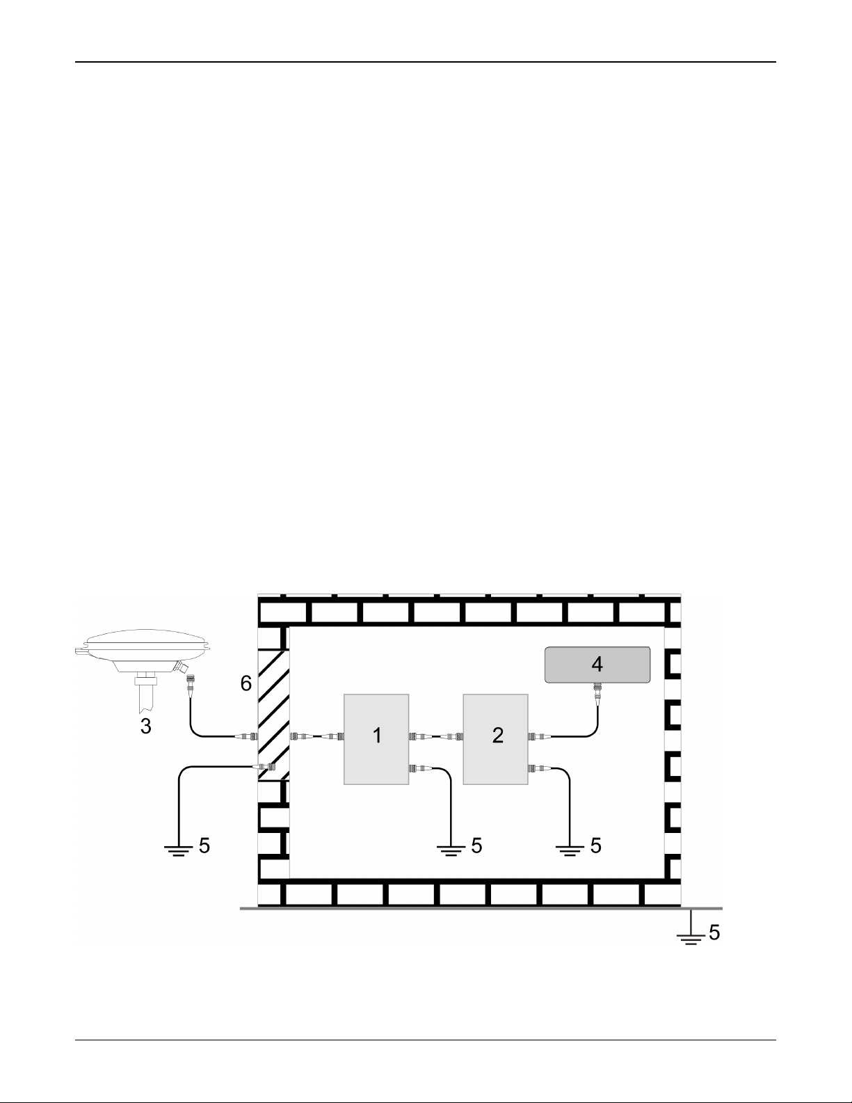
The primary and secondary lightning protections should be as close to the building's entrance
as possible. Where feasible, mount onto the grounding plate itself (refer to the figure
below).
OEM7 Installation and Operation User Manual v1 10
Notices
Ref# Description
1 Primary lightning protection device
2 Secondary lightning protection device
3 External antenna
4 GNSS Receiver
5 To ground
6 Grounding plate or grounding point at the building’s entrance
Acceptable choices for earth grounds, for central buildings, are:
l
Grounded interior metal cold water pipe within five feet (1.5 m) of the point where
it enters the building
l
Grounded metallic service raceway
l
Grounded electrical service equipment enclosure
l
Eight-foot grounding rod driven into the ground (only if bonded to the central building ground by #6, or heavier, bonding wire)
These installation instructions are the minimum requirements for receiver and antenna installations.
Where applicable, follow the electrical codes for the country of installation. Examples of country
codes include:
l
USA National Electrical Code (NFPA 70)
l
Canada Canadian Electrical Code (CSA C22)
l
UK British Standards Institute (BSI 7671)
Conventions
The following conventions are used in this manual:
Information that supplements or clarifies text.
A caution that actions, operation or configuration may lead to incorrect or improper
use of the hardware.
A warning that actions, operation or configuration may result in regulatory
noncompliance, safety issues or equipment damage.
OEM7 Installation and Operation User Manual v1 11
Customer Support
NovAtel Knowledge Base
If you have a technical issue, visit the NovAtel Support page at www.novatel.com/support.
Through the Support page, you can contact Customer Support, find papers and tutorials or down-
load current manuals and the latest firmware.
Before Contacting Customer Support
Before you contact NovAtel Customer Support about a software problem, perform the following
steps:
If logging data over an RS-232 serial cable, ensure that the configured baud rate can support the data bandwidth (see SERIALCONFIG command). NovAtel recommends a min-
imum suggested baud rate of 115200 bps.
1.
Log the following data to a file on your computer for 15 minutes:
RXSTATUSB once
RAWEPHEMB onchanged
GLORAWEPHEMB onchanged
BESTPOSB ontime 1
RANGEB ontime 1
RXCONFIGA once
VERSIONA once
For SPAN systems, include the following logs in the file created on your computer:
RAWIMUSXB onnew
INSUPDATESTATUSB onnew
INSPVAXB ontime 1
INSCONFIGA once
2.
Send the data file to NovAtel Customer Support: support@novatel.com
3.
You can also issue a FRESET command to the receiver to clear any unknown settings.
The FRESET command will erase all user settings. You should know your configuration
(by requesting the RXCONFIGA log) and be able to reconfigure the receiver before you
send the FRESET command.
If you are having a hardware problem, send a list of the troubleshooting steps taken and the results.
Contact Information
Log a support request with NovAtel Customer Support using one of the following methods:
Log a Case and Search Knowledge:
OEM7 Installation and Operation User Manual v1 12

Customer Support
Website: www.novatel.com/support
Log a Case, Search Knowledge and View Your Case History: (login access required)
Web Portal: https://novatelsupport.force.com/community/login
E-mail:
support@novatel.com
Telephone:
U.S. and Canada:1-800-NOVATEL (1-800-668-2835)
International:+1-403-295-4900
OEM7 Installation and Operation User Manual v1 13

Chapter 1 Introduction
The OEM7 family offers Global Navigation Satellite System (GNSS) receivers and integrated
L-Band capability. The OEM7 family supports existing and planned GPS, GLONASS, BeiDou,
Galileo and QZSS frequencies and is capable of full code and Real-Time Kinematic (RTK) positioning. OEM7 cards are designed for flexibility of integration and configuration.
OEM7 Family Receiver Cards
l
OEM719 - refer to OEM719 Receiver Overview on page16 for details
l
OEM729 - refer to OEM729 Receiver Overview on page16 for details
l
OEM7700 - refer to OEM7700 Receiver Overview on page17 for details
1.1 Related Documents and Information
After the OEM7 hardware is set up, the OEM7 Commands and Logs Reference Manual (OM-
20000169) becomes the primary source for command and log information. Each receiver has a
specific set of features, so some commands and logs may not be supported by your model.
Refer also to our web site www.novatel.com/support/ for the latest documentation.
This manual does not cover OEM7 service and repair. Contact a local NovAtel dealer for service
or repair inquiries (refer to Customer Support on page12 for contact details).
1.2 OEM7 Receiver System Overview
In addition to the NovAtel OEM7 receiver card, an OEM7 receiver system requires the following:
l
Enclosure and wiring harness
l
Power supply
l
Data communications equipment
l
GNSS antenna
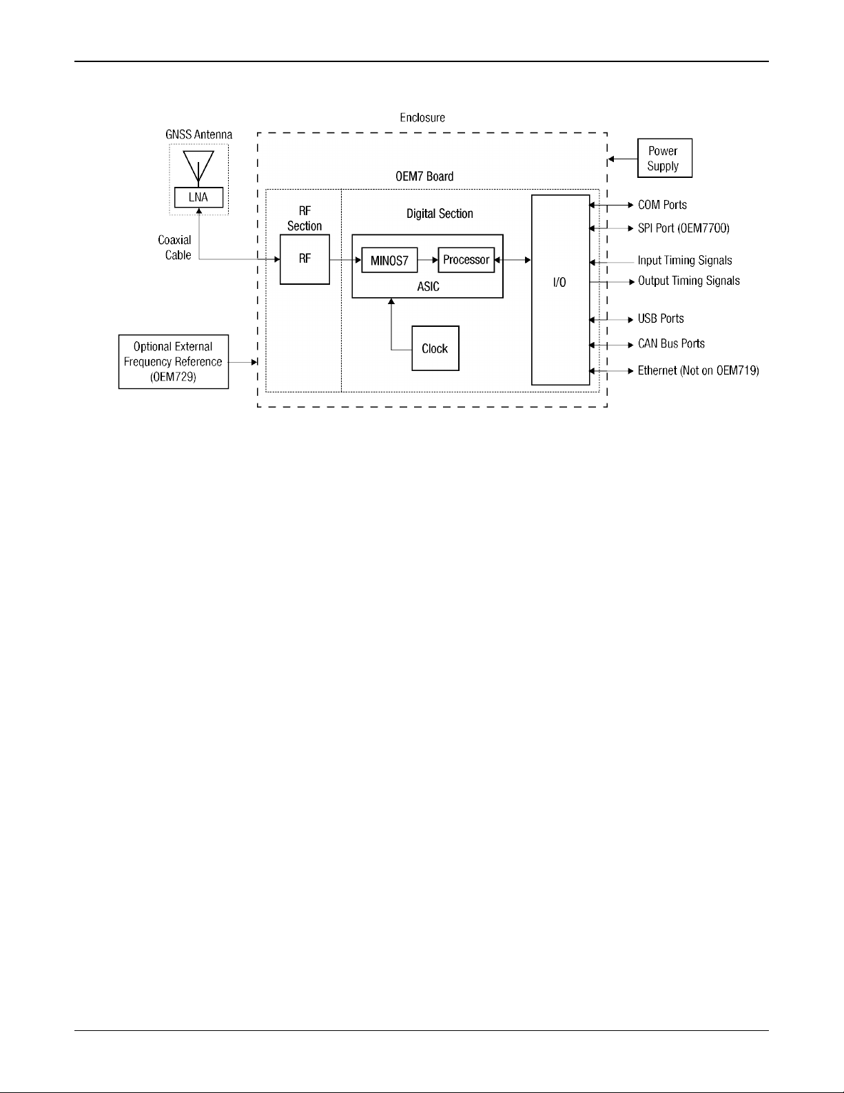
An OEM7 receiver system is illustrated in Figure 1: OEM7 Receiver System on the next page and
described in the sections that follow.
OEM7 Installation and Operation User Manual v1 14
Chapter 1 Introduction
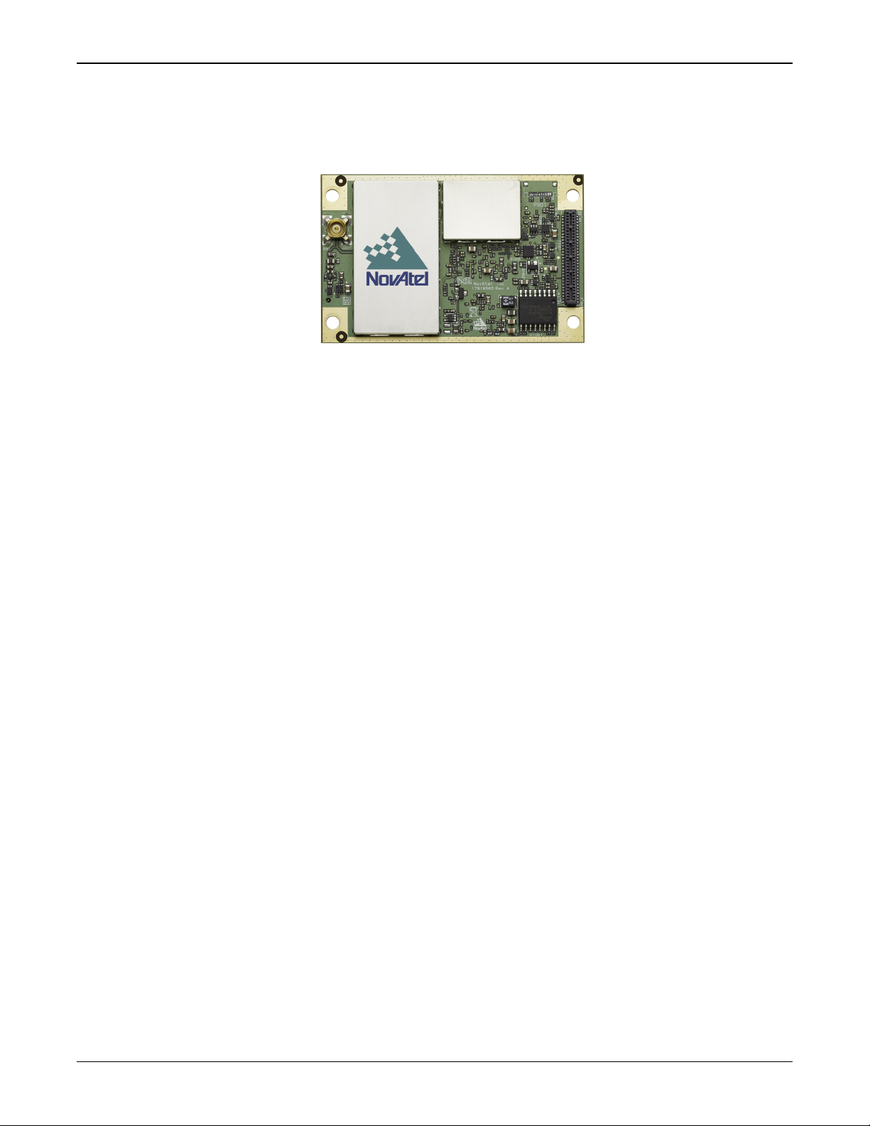
1.2.1 OEM7 Family Card
Figure 1: OEM7 Receiver System
NovAtel’s OEM7 family cards consist of a Radio Frequency (RF) section and a digital section.
Radio Frequency (RF) Section
The receiver obtains GNSS signals from the antenna. The RF section down converts the incoming
RF signals to Intermediate Frequency (IF) signals which are processed by the digital section.
The RF section also supplies power to the active antenna Low Noise Amplifier (LNA) through the
coaxial cable. The RF section has been designed to reject common sources of interference.
Digital Section
The heart of the digital section is NovAtel’s MINOS7 ASIC (Application Specific Integrated Circuit). The digital section digitizes and processes the IF signals to obtain a GNSS solution (position, velocity and time). It also processes the system I/O, shown in Figure 1: OEM7 Receiver
System above.
1.2.2 Enclosure
An enclosure is necessary to protect the OEM7 family card from environmental extremes (moisture, dust, etc.).
1.2.3 GNSS Antenna
The receiver can supply power for the antenna LNA. If the antenna is not compatible with the
OEM7 power supply (5 VDC), an external LNA supply may be required.
1.2.4 Power Supply
A power supply capable of delivering the minimum receiver operating voltage and power is
required. See Power Supply Requirements for Receiver Cards on page20 for details.
OEM7 Installation and Operation User Manual v1 15
Chapter 1 Introduction
1.2.5 Optional External Frequency Reference
When applications require greater precision than the OEM7 internal clock, connect the receiver
to an external high stability oscillator. See External Oscillator on page70 for more information.
An External Oscillator is supported only on the OEM729.
1.2.6 Data Communications Equipment
A computer or other data communications device is necessary to communicate with the receiver
and to receive and store the data that the receiver provides.
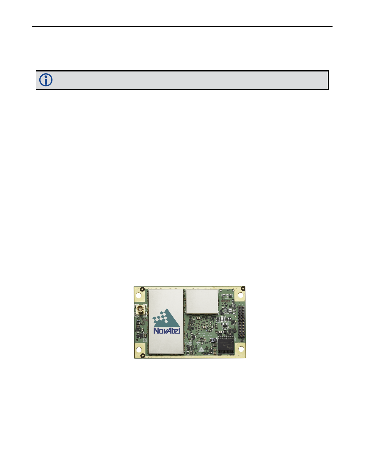
1.2.7 OEM719 Receiver Overview
The OEM719 has the same form and fit as NovAtel’s OEM615™ receiver, with the following features:
l
Four-frequency/Multi-constellation:
GPS L1, L1C, L2C, L2P, L5; GLONASS L1, L2, L2P, L3; BeiDou B1, B2, B3; Galileo E1, E5, E5a,
E5b, E6, AltBOC; SBAS L1, L5, QZSS L1, L1C, L2C, L5, L6
l
555 channel operation
l
LVCMOS UART communications ports
l
USB device port (with virtual COMports)
l
Internal LNA power supply
l
NovAtel CORRECT positioning (with PPP, RTK, SBAS and DGPS solutions)
l
GLIDE and ALIGN positioning options
l
Enhanced interference mitigation
l
Mechanical mounting rails
Figure 2: OEM719 Receiver Board
OEM719 technical specifications are provided in OEM719 Technical Specifications on page110.
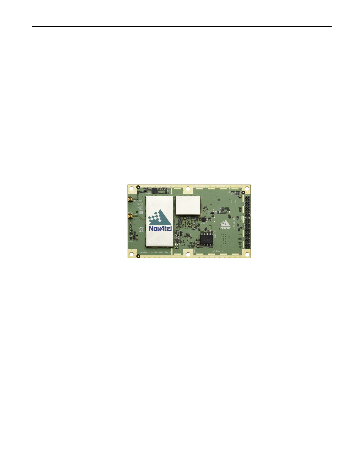
1.2.8 OEM729 Receiver Overview
The OEM729 has the same form and fit as NovAtel’s OEM628™ receiver, with the following features:
OEM7 Installation and Operation User Manual v1 16
Chapter 1 Introduction
l
Four-frequency/Multi-constellation:
GPS L1, L1C, L2C, L2P, L5; GLONASS L1, L2, L2P, L3; BeiDou B1, B2, B3; Galileo E1, E5, E5a,
E5b, E6, AltBOC; SBAS L1, L5, QZSS L1, L1C, L2C, L5, L6
l
555 channel operation
l
External oscillator input
l
RS-232/RS-422 communications port
l
LVCMOS UART communications ports
l
USB device port (with virtual COMports)
l
Ethernet communications port
l
NovAtel CORRECT positioning (with PPP, RTK, SBAS and DGPS solutions)
l
GLIDE and ALIGN positioning options
l
Enhanced interference mitigation
l
Mechanical mounting rails
Figure 3: OEM729 Receiver Board
OEM729 technical specifications are provided in OEM729 Technical Specifications on page130.
1.2.9 OEM7700 Receiver Overview
The OEM7700 is the same size as NovAtel’s OEM615™ receiver with the following features:
l
Four-frequency/Multi-constellation:
GPS L1, L1C, L2C, L2P, L5; GLONASS L1, L2, L2P, L3; BeiDou B1, B2, B3; Galileo E1, E5, E5a,
E5b, E6, AltBOC; SBAS L1, L5, QZSS L1, L1C, L2C, L5, L6
l
555 channel operation
l
LVCMOS UART communications ports
l
USB communications ports
l
Ethernet communications port
l
High density connector for increased connectivity options
l
Small form factor
l
NovAtel CORRECT positioning (with PPP, RTK, SBAS and DGPS solutions)
l
GLIDE and ALIGN positioning options
OEM7 Installation and Operation User Manual v1 17
Chapter 1 Introduction
l
Enhance interference mitigation
l
Mechanical mounting rails
Figure 4: OEM7700 Receiver Board
OEM7700 technical specifications are provided in OEM7700 Technical Specifications on page150.
OEM7 Installation and Operation User Manual v1 18
Chapter 2 Installation of OEM7 Family Receiver Cards
This chapter provides instructions and guidelines for checking the contents of the shipping box,
installing the NovAtel PC utilities on a computer, integrating a NovAtel receiver into a GNSS
receiver system.
2.1 Shipping Box
The following items are provided with the OEM7 cards:
l
OEM7 Family Receiver Card
l
OEM7 Family Receivers Quick Start Guide
2.2 Additional Equipment Required
For the receiver to perform optimally, the following additional equipment is required:
l
Interface cable for power, communications and other signals
l
Enclosure to protect against the environment
l
GNSS antenna (for a list of NovAtel GNSS antennas refer to our web site www.nova-
tel.com/antennas)
l
Coaxial cable (and interconnect adapter cable, as necessary)
l
Data communication equipment capable of serial, USB or Ethernet communication
l
Serial, USB or Ethernet data cable
l
Power supply
l
Optional NovAtel OEM7 Development Kit (01019433)
OEM7 Development Kit Guide (GM-14915145)
When the OEM7 family receiver is installed in a permanent location, it should be protected by a lightning protection device according to local building codes (refer to the
Lightning Protection Installation and Grounding Procedure on page9).
Emissions
OEM7 family products have been designed and tested to meet regulatory emission
limits. Emission levels may be higher for OEM7 family card level operation than for
integrated enclosure level products using an OEM7 family card.
Refer to Notices on page8 for more information.
2.3 Selecting a GNSS Antenna
NovAtel offers a variety of antennas, including single, dual and triple-frequency, triple-band and
wide-band reference GNSS antennas (refer to our web site: www.novatel.com/antennas for
details of available antennas). All antennas include band pass filtering and an LNA. The GNSS
antenna chosen depends on the particular application. Each model offers exceptional phase
OEM7 Installation and Operation User Manual v1 19
Chapter 2 Installation of OEM7 Family Receiver Cards
center stability and a significant measure of immunity against multipath interference. Each
antenna has an environmentally sealed radome and all meet the European Union’s Restriction of
Hazardous Substances (RoHS) and Waste Electrical and Electronic Equipment (WEEE).
If a non-NovAtel GNSS antenna is chosen, a typical antenna LNA gain between 26 dB to 30 dB is
recommended in a rover station application.
For more information about antenna selection, see Importance of Antenna Selection on
page183.
2.4 Choosing a Coaxial Cable
An appropriate coaxial cable matches the impedances of the antenna and receiver (50 ohms)
and has a line loss not exceeding 10.0 dB. If the limit is exceeded, excessive signal degradation
may occur and the receiver may not meet performance specifications. NovAtel offers several
coaxial cables to meet GNSS antenna interconnection requirements, including:
l
5, 15 and 30 m antenna cable with TNC connectors on both ends (NovAtel part numbers GPSC006, GPS-C016 and GPS-C032)
A conversion is required between the MMCX, MMBX or MCX connector on the OEM7
receiver and the female TNC connector on NovAtel’s GNSS antennas.
NovAtel recommends using high quality coaxial cables because an impedance
mismatch is possible when using lower quality cables and this produces reflections
in the cable that increases signal loss. Although other high quality antenna cables
can be used, the performance specifications of the OEM7 family receivers are
warranted only when used with NovAtel supplied accessories.
2.5 Power Supply Requirements for Receiver Cards
OEM7 receivers require a power supply that provides:
l
+3.3 VDC ±5% with less than 100 mV ripple
If the voltage supplied is below the minimum specification, the receiver suspends
operation.
If the voltage supplied is above the maximum specification, the receiver may be
permanently damaged, voiding the warranty.
OEM7 family cards contain a DC-to-DC converter, tolerant to input noise and ripple.
A tightly regulated input supply is not required, as long as it falls within the given
input range.
Refer to the following for complete power specifications:
l
OEM719 Electrical and Environmental Specifications on page120
l
OEM729 Electrical and Environmental Specifications on page136
OEM7 Installation and Operation User Manual v1 20
Chapter 2 Installation of OEM7 Family Receiver Cards
l
OEM7700 Electrical and Environmental Specifications on page156
2.6 Card Installation Overview
When the appropriate equipment is selected, complete the following steps to set up and begin
using the NovAtel GNSS receiver.
1.
Ensure adequate ESD protection is used as described in Electrostatic Discharge (ESD) Pre-
cautions below.
2.
Prepare the interface with the receiver’s data, status and power signals using the information in Preparing the Data, Signal and Power Interface on page27.
3.
Connect the GNSS antenna adapter cable to the receiver (refer to Connecting the Antenna to
the Receiver Card on page32).
4.
Mount the OEM7 family card in a secure enclosure to reduce environmental exposure and RF
interference, as described in Mounting the Printed Circuit Board below.
5.
Mount the GNSS antenna to a secure, stable structure (refer to Mounting the GNSS Antenna
on page31).
6.
Apply power to the receiver as described in Applying Power to the Receiver Card on page33.
7.
Connect the receiver to a computer or other data communications equipment (refer to Con-
necting Data Communications Equipment on page33 for instructions).
2.6.1 Electrostatic Discharge (ESD) Precautions
When the OEM7 family card is removed from the original packing box, keep the box and ESD protection for future storage or shipment. Leave the OEM7 family card in the static shielding bag or
clamshell when not connected in a normal operating environment.
l
Always wear a properly grounded anti-static wrist strap when handling OEM7
cards.
l
Always hold the OEM7 family card by the corners or the RF shield: avoid direct
contact with any of the components.
l
Never let the OEM7 family card come in contact with clothing. The ground
strap cannot dissipate static charges from fabrics.
l
Failure to follow accepted ESD handling practices could cause damage to the
OEM7 family card.
l
The warranty may be void if equipment is damaged by ESD.
For more ESD information, see Electrostatic Discharge (ESD) Practices on page188.
2.7 Mounting the Printed Circuit Board
The OEM7 family receiver cards are OEM products and the printed circuit board is provided
without a housing structure. This allows flexibility in creating a mounting environment to suit particular product and market requirements.
The mounting and enclosure should provide for the following:
OEM7 Installation and Operation User Manual v1 21
Chapter 2 Installation of OEM7 Family Receiver Cards
l
Mounting of external connectors
l
Protection from hostile physical environments (rain, snow, sand, salt, water, extreme temperatures, etc)
The OEM Integrator is responsible for ensuring compliance of the final
product with the regulatory bodies for those intended markets.
l
Protection from ESD (see Electrostatic Discharge (ESD) Practices on page188)
l
Location to securely mount the receiver using screws
2.7.1 Planning the Mount Location
When planning the mount location for the OEM7 receiver, ensure there is enough room for the
card. There is an area around the card, called a keep-out zone, where other components in the
enclosure do not intrude. This keep-out zone is intended to prevent other components in the
enclosure from interfering with, or damaging, the OEM7 receiver. For diagrams of the exact
dimensions and keep-out zones for each OEM7 receiver card, see:
l
OEM719 Mechanical Specifications on page113
l
OEM729 Mechanical Specifications on page133
l
OEM7700 Mechanical Specifications on page153
OEM7 receivers are not directional in nature and can be mounted in any orientation.
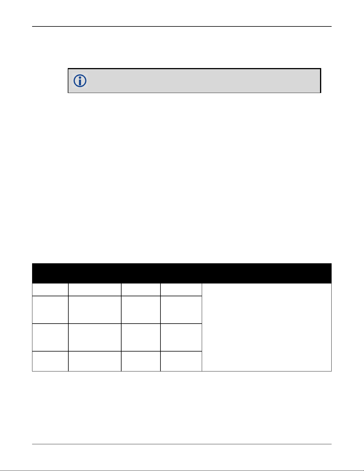
2.7.2 Board to Board Spacing
A minimum amount of space is required between the OEM7 receiver and the interface or system
board the receiver connects to. Refer to the following table for the minimum and suggested spacing.
OEM7
Receiver
OEM719 MCX straight 11.00mm 12.00 mm
OEM719A MCX right angle 7.00 mm
OEM719B MMBX straight 7.00 mm
OEM7700 MMBX straight 7.00 mm
Antenna Con-
nector Type
Minimum
Spacing
Suggested
Spacing
7.00 mm
10.00 mm
12.00 mm
7.00 mm
10.00 mm
12.00 mm
7.00 mm
10.00 mm
Notes
Mounting rails are available from
NovAtel.
See Table 1: NovAtel Mounting Rails on
page26 for the rails available.
OEM7 Installation and Operation User Manual v1 22
Chapter 2 Installation of OEM7 Family Receiver Cards
The recommended minimum values in the previous table assumes no recesses or
cut-outs in the interface or system board for antenna connection.
A component keep-out area may be needed below the antenna connector on the
mating interface or system board to facilitate minimum or suggested spacing.
Board to board spacing less than the minimum spacing suggested in the table may
be achieved by incorporating recesses or cut-outs in mating interface or system
board.
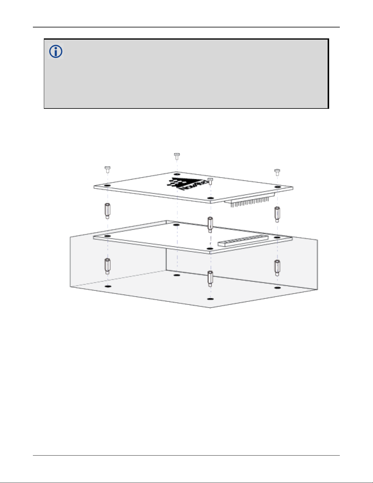
2.7.3 Mounting Options
OEM7 receivers can be mounted using standoffs, rails or rails and edge clamping.
Figure 5: Mounting with Standoffs
OEM7 Installation and Operation User Manual v1 23
Chapter 2 Installation of OEM7 Family Receiver Cards
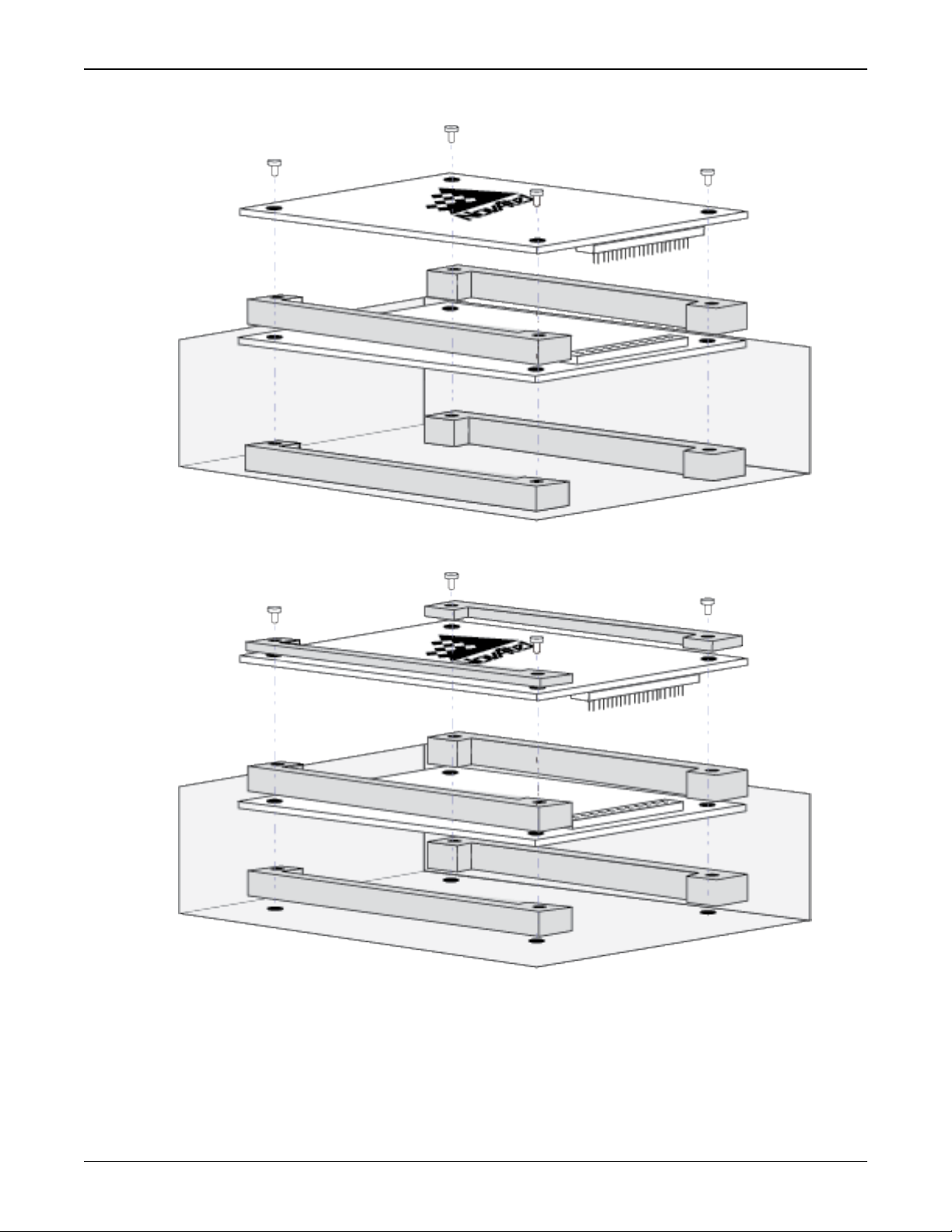
Figure 6: Mounting with Rails
Figure 7: Mounting with Rails and Edge Clamps
The mounting holes in the OEM7 receiver cards accept M3 fasteners with a maximum projected
head diameter of 7.5 mm (0.295"). For the exact spacing of the mounting holes, see Figure 39:
OEM719 Dimensions on page113, Figure 46: OEM729 Dimensions on page133 and Figure 49:
OEM7700 Dimensions on page153.
OEM7 Installation and Operation User Manual v1 24
Chapter 2 Installation of OEM7 Family Receiver Cards
For proper grounding and mechanical integrity, mount the OEM719 and OEM7700 with
four screws.
For proper grounding and mechanical integrity, mount the OEM729 with six screws.
When installing cards, ensure all standoffs are properly installed.
Also ensure that the mounting location (whether using standoffs, bosses or rails) is
level.
The amount of board deflection (bow and twist) must not exceed 0.75% of the
receiver card's characteristic dimension. For example, on the OEM7700, which is 71
mm long and 46 mm wide, the deflection along the length must not exceed 0.53 mm
and the deflection along the width must not exceed 0.34 mm.
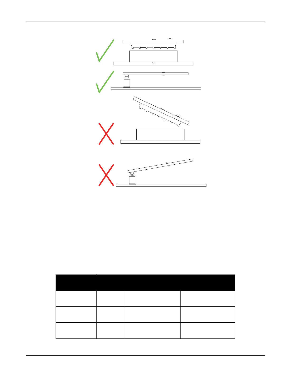
Care needs to be taken when mating the OEM7700 receiver to an interface card or
system board. The high-density, 60 position connectors on both cards need to be
properly aligned before mating to prevent damage to the connectors. See Figure 8:
Mounting the High-Density, 60 Pin Connector on the next page.
A method to ensure proper alignment of the connectors is to slowly bring the mating
faces together and let the connectors find their centers as the mating faces come to
rest against each other. At this stage, visually check that the connectors are aligned.
If the connectors are aligned, gently push the connectors together to mate them.
A fixture or jig will also be of help in ensuring proper alignment between the two
connectors.
OEM7 Installation and Operation User Manual v1 25
Chapter 2 Installation of OEM7 Family Receiver Cards
Figure 8: Mounting the High-Density, 60 Pin Connector
OEM7 receivers have an area on the edge of the cards to allow the use of mounting rails. This is
the area of bare copper outside of the keep-out zone. On the OEM719 and OEM7700, this area is
1.75 mm wide. On the OEM729, this area is 2.5mm wide. See Figure 45: OEM719 Mounting Sur-
face on page119, Figure 48: OEM729 Mounting Surfaces on page135 and Figure 51: OEM7700
Mounting Surfaces on page155 for the dimensions of this area.
For most non-demanding applications (e.g. base stations, remote sensing, desktop units and IT
infrastructure), standoffs or bosses are sufficient to provide a secure mounting location.
Using rails to mount the OEM7 receiver improves the thermal and vibration performance of the
receiver. Securing the OEM7 receiver to mounting rails using clamping bars provides the most
secure configuration for aggressive thermal and vibration applications. See Table 1: NovAtel
Mounting Rails below for information about the OEM7 mounting rails available from NovAtel.
Table 1: NovAtel Mounting Rails
Rail Part
Number
01019518 7 mm
01019519 10 mm
01019634 12 mm OEM719
Rail
Height
Use as Mounting
Rail for
OEM719
OEM7700
OEM719
OEM7700
Use as Clamping
Bar on
OEM719
OEM7700
OEM719
OEM7700
OEM719
OEM7700
OEM7 Installation and Operation User Manual v1 26
Chapter 2 Installation of OEM7 Family Receiver Cards
Ensure the IO connector height and antenna cable/connector height facilitate the desired
board to board spacing and do not violate OEM7 receiver card height keep-out zones.
For more details about mounting OEM7 receiver cards, refer to the OEM7 Receiver Card
Mechanical Integration Application Note (D19021).
2.7.4 Thermal dissipation
To ensure functionality and reliability, the OEM7 receiver cards must operate within the specified ambient air temperature limits (-40°C to +85°C).
The OEM7 receivers have been designed to efficiently transfer heat from the receiver components into the printed circuit board. Mounting the OEM7 receiver on rails, or attaching heat
sinks to the mounting areas, will transfer the heat from the receiver card to adjacent circuit
boards, the enclosure or the air.
The mounting area is the area of bare copper on the sides of the receiver that are outside of the keep-out zone. See Figure 45: OEM719 Mounting Surface on page119, Figure
48: OEM729 Mounting Surfaces on page135 and Figure 51: OEM7700 Mounting Surfaces
on page155.
For more information about thermal dissipation, refer to the OEM7 Receiver Card Mech-
anical Integration Application Note (D19021).
2.7.5 Vibration
OEM7 receivers are rated to 20g RMS (MIL-STD_810G Method 514.6E-1, Category 24). However,
for high vibration installations, special considerations are required.
For OEM719 and OEM7700 receiver cards to meet the 20g vibration rating, the receiver card
must be mounted using rails. OEM729 receivers meet the 20g vibration rating using standoffs,
bosses or rails.
For more information about vibration considerations, refer to the OEM7 Receiver Card
Mechanical Integration Application Note (D19021).
2.8 Preparing the Data, Signal and Power Interface
The interface provides connections to some or all of the following:
l
Communication ports, including COM, Ethernet, USB and CAN
l
Input and output timing strobes
l
Power input
OEM7 Installation and Operation User Manual v1 27

Chapter 2 Installation of OEM7 Family Receiver Cards
l
RF signal input
l
Optional external frequency reference
For all OEM7 family cards, the power, status and data inputs and outputs are accessed from one
connector. The interface therefore, must be designed to mate with this connector.
Table 2: OEM7 Communication and I/O Connectors
Receiver COM and I/O Connector Mating Connector
OEM719
OEM729
OEM7700
2 x 10 male header (2 mm pitch)
See OEM719 Interface Connector on
page126
Main: 2 x 12 male header (2 mm pitch)
Aux: 2 x 8 male header (2 mm pitch)
See OEM729 Interface Connectors on
page142
2 x 30 female socket (0.8 mm pitch)
See OEM7700 Interface Connector on
page162
2 x 10 female socket (2 mm pitch)
Main: 2 x 12 female socket (2 mm
pitch)
Aux: 2 x 8 female socket (2 mm pitch)
2 x 30 male header (0.8 mm pitch)
Samtec TEMS-130-02-07.0-H-D-A-KTR
(10 mm mated stack height)
Samtec TEMS-130-02-04.0-H-D-A-KTR
(7 mm mated stack height)
OEM7 Installation and Operation User Manual v1 28
Chapter 2 Installation of OEM7 Family Receiver Cards
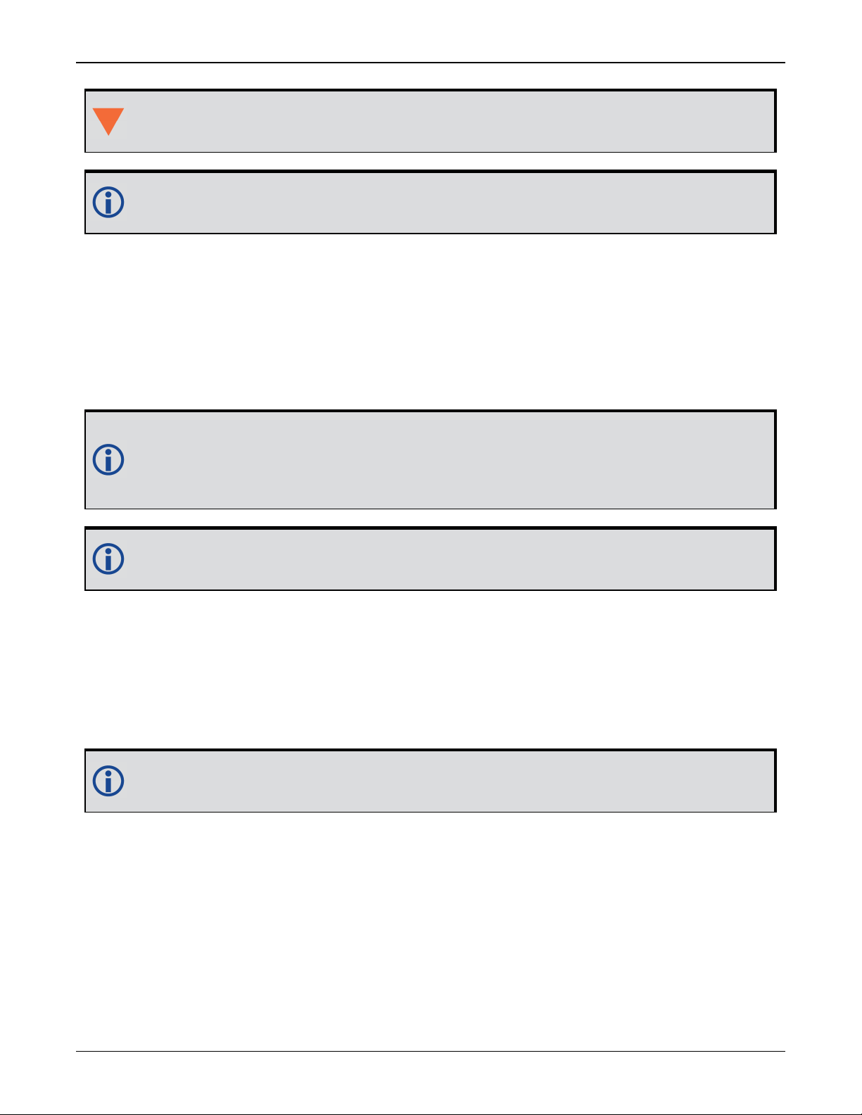
Figure 9: OEM719 Connector and Indicator Locations
Bottom View
Top View
OEM7 Installation and Operation User Manual v1 29
Chapter 2 Installation of OEM7 Family Receiver Cards
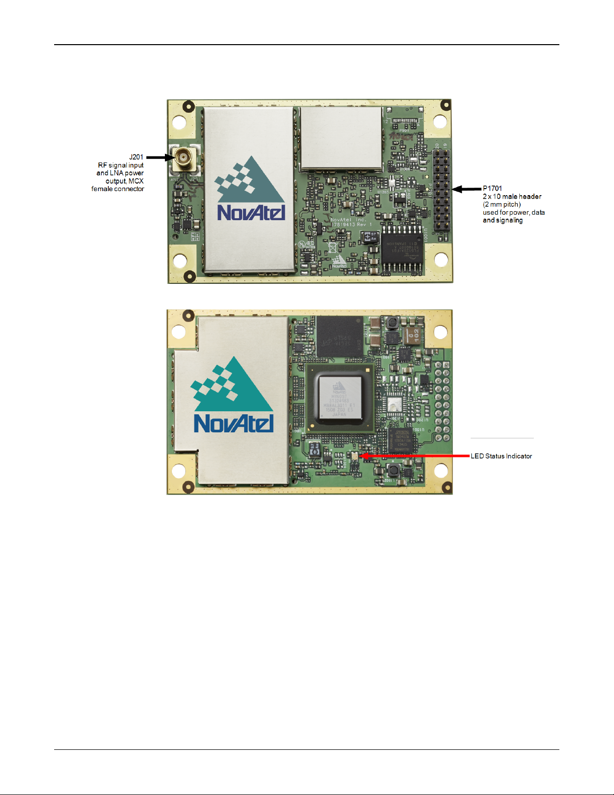
Figure 10: OEM729 Connector and Indicator Locations
Bottom View
Top View
OEM7 Installation and Operation User Manual v1 30
 Loading...