

Novatel OEM615, OEM617, OEM638, OEM617D, FlexPak6 Installation And Operation Manual
...
OEM6® Family
OEM615, OEM617, OEM617D, OEM628 and OEM638 cards
and
FlexPak6 and FlexPak6D enclosures
Installation and Operation
User Manual

OEM6 Family - Installation and Operation User Manual
Publication Number: OM-20000128
Revision Level: 12
Revision Date: October 2016
To download the latest firmware and/or software visit: www.novatel.com/support/firmware-downloads
This manual reflects firmware version 6.710/OEM0607100RN000
Warranty
NovAtel® Inc. warrants that its GNSS products are free from defects in materials and workmanship, subject to
the conditions set forth on our web site: www.novatel.com/products/warranty/
®
OEM6
FlexPak6™ and FlexPak6D™ One (1) Year
GPS Antenna Series One (1) Year
Cables and Accessories Ninety (90) Days
Software Warranty One (1) Year
Card Receivers One (1) Year
.
Return Instructions
To return products, refer to the instructions found under the Return Policy Tab on the warranty page:
www.novatel.com/products/warranty/
.
Proprietary Notice
.
Information in this document is subject to change without notice and does not represent a commitment on the
part of NovAtel Inc. The software described in this document is furnished under a license agreement or nondisclosure agreement. The software may be used or copied only in accordance with the terms of the
agreement. It is against the law to copy the software on any medium except as specifically allowed in the
license or non-disclosure agreement.
The information contained within this manual is believed to be true and correct at the time of publication.
OEM6, ALIGN, SPAN and NovAtel are registered trademarks of NovAtel Inc.
FlexPak6, FlexPak6D, OEM615, OEM617, OEM617D, OEM628, OEM638, GLIDE, OEMV-1, OEMV-2,
OEMV-3, NovAtel CORRECT and NovAtel Connect are trademarks of NovAtel Inc.
All other brand names are trademarks of their respective holders.
Manufactured and protected under U.S. patents.
#5,101,416 #6,184,822 B1
#5,390,207 #6,243,409 B1
#5,414,729 #6,445,354 B1
#5,495,499 #6,608,998 B1
#5,736,961 #6,664,923 B1
#5,809,064 #7,738,536
© Copyright 2016 NovAtel Inc. All rights reserved.
Unpublished rights reserved under International copyright laws.
OEM6 Family Installation and Operation User Manual Rev 12 2

Table of Contents
Notices ............................................................................................................................... 13
FCC Notices ............................................................................................................................................... 13
Industry Canada .........................................................................................................................................13
CE Marking.................................................................................................................................................14
WEEE ......................................................................................................................................................... 14
RoHS .......................................................................................................................................................... 14
REACH ....................................................................................................................................................... 14
Ethernet Port ..............................................................................................................................................14
Lightning Protection Installation and Grounding Procedure .......................................................................15
Conventions................................................................................................................................................ 17
Customer Support............................................................................................................. 18
NovAtel Knowledge Base ........................................................................................................................... 18
Before Contacting Customer Support.........................................................................................................18
Contact Information ....................................................................................................................................18
1 Introduction ...................................................................................................................19
1.1 Overview of the OEM6 Family of Cards and Enclosures ...................................................................19
1.1.1 OEM6 Family Receiver Cards .................................................................................................19
1.1.2 OEM6 Receiver Enclosure ......................................................................................................19
1.2 Related Documents and Information.................................................................................................. 19
1.2.1 OEM615 Receiver ...................................................................................................................20
1.2.2 OEM617 Receiver ...................................................................................................................20
1.2.3 OEM617D Receiver.................................................................................................................21
1.2.4 OEM628 Receiver ...................................................................................................................21
1.2.5 OEM638 Receiver ...................................................................................................................22
1.3 OEM6 Receiver System Overview .....................................................................................................23
1.3.1 OEM6 Family Card ..................................................................................................................24
1.3.2 Enclosure.................................................................................................................................24
1.3.3 GNSS Antenna ........................................................................................................................25
1.3.4 Power Supply .......................................................................................................................... 25
1.3.5 Optional External Frequency Reference .................................................................................25
1.3.6 Data Communications Equipment ........................................................................................... 25
1.3.7 Onboard Memory ....................................................................................................................25
1.4 OEM6 Enclosures .............................................................................................................................. 26
1.4.1 FlexPak6.................................................................................................................................. 26
1.4.2 FlexPak6D ............................................................................................................................... 27
2 Installation OEM6 Family Cards................................................................................... 28
2.1 Shipping Box ......................................................................................................................................28
2.2 Additional Equipment Required.......................................................................................................... 28
2.3 Selecting a GNSS Antenna ................................................................................................................29
2.3.1 Choosing a Coaxial Cable .......................................................................................................29
2.3.2 Mounting the GNSS Antenna ..................................................................................................29
2.3.3 Connecting the Antenna to the Receiver.................................................................................30
2.4 Power Supply Requirements.............................................................................................................. 31
2.5 Card Installation Overview ................................................................................................................. 32
2.5.1 Installing an OEM6 Family Card with Wiring Harness and Enclosure..................................... 32
2.5.2 Applying Power to the Receiver .............................................................................................. 38
2.5.3 Connecting Data Communications Equipment........................................................................38
2.6 OEM638 Card Security ...................................................................................................................... 43
2.6.1 Administration Password .........................................................................................................43
OEM6 Family Installation and Operation User Manual Rev 12 3

2.6.2 FTP Server and ICOM Port ....................................................................................................43
2.7 Installing NovAtel PC Utilities .............................................................................................................43
3 Installation FlexPak6 & FlexPak6D Enclosures.......................................................... 44
3.1 Shipping Box ......................................................................................................................................44
3.2 Additional Equipment Required.......................................................................................................... 44
3.3 Selecting a GNSS Antenna ................................................................................................................44
3.3.1 Choosing a Coaxial Cable .......................................................................................................45
3.3.2 Mounting the GNSS Antenna ..................................................................................................45
3.3.3 FlexPak6 and FlexPak6D Alternative Power Source ..............................................................47
3.3.4 Battery Backup ........................................................................................................................49
3.3.5 FlexPak6 Status Indicators and Connector Labels.................................................................. 49
3.3.6 FlexPak6D Status Indicators and Connector Labels ............................................................... 50
3.4 Installing NovAtel PC Utilities .............................................................................................................50
4 Operation OEM6 Cards and Enclosures ..................................................................... 51
4.1 Communications with the Receiver .................................................................................................... 51
4.1.1 Serial Ports ..............................................................................................................................52
4.1.2 Communicating with a Remote Terminal.................................................................................53
4.1.3 Communicating with a Computer ............................................................................................ 53
4.2 Getting Started ...................................................................................................................................54
4.2.1 Starting the Receiver ...............................................................................................................54
4.2.2 Communicating with the Receiver Using NovAtel Connect .....................................................54
4.3 Transmitting and Receiving Corrections ............................................................................................ 55
4.3.1 Base Station Configuration...................................................................................................... 57
4.3.2 Rover Station Configuration .................................................................................................... 59
4.3.3 ALIGN
4.3.4 PDP and GLIDE
4.4 STEADYLINE® .................................................................................................................................. 60
4.4.1 Maintain ...................................................................................................................................61
4.4.2 Transition.................................................................................................................................61
4.4.3 Prefer Accuracy .......................................................................................................................62
4.4.4 UAL.......................................................................................................................................... 62
4.5 Configuration Notes............................................................................................................................64
4.6 Enabling SBAS Positioning ................................................................................................................64
4.7 Enabling L-Band................................................................................................................................. 65
4.7.1 TerraStar Subscriptions........................................................................................................... 65
4.7.2 Veripos Subscriptions.............................................................................................................. 66
4.7.3 OmniSTAR®............................................................................................................................ 66
4.8 RTK ASSIST™...................................................................................................................................67
4.9 Transferring Time Between Receivers ...............................................................................................68
4.9.1 GPS to Receiver Time Synchronization ..................................................................................68
4.9.2 Time Definitions....................................................................................................................... 68
4.9.3 Procedures to Transfer Time................................................................................................... 69
4.10 Additional Features and Information (Card and Enclosure) ............................................................. 73
4.10.1 Universal Serial Bus (USB) ................................................................................................... 73
4.10.2 CAN Bus (not available on the FlexPak6D)........................................................................... 74
4.10.3 Strobes ..................................................................................................................................75
4.10.4 Status Indicator......................................................................................................................75
4.10.5 External Oscillator ................................................................................................................. 76
4.10.6 Antenna LNA Power ..............................................................................................................77
4.10.7 Ethernet ..............................................................................................................................77
4.11 Logging and Retrieving Data Overview ...........................................................................................78
4.11.1 Onboard Memory...................................................................................................................78
4.11.2 Remote Logging Initiation...................................................................................................... 78
® Heading Master and Remote Configurations ............................................................59
™
Configurations............................................................................................60
OEM6 Family Installation and Operation User Manual Rev 12 4

4.11.3 Manual Retrieval of Logged Data .......................................................................................... 78
4.11.4 Remote Retrieval of Logged Data ......................................................................................... 78
4.11.5 Naming Logs ......................................................................................................................... 79
4.11.6 Manual Log File Naming........................................................................................................79
4.11.7 Stop Logging ......................................................................................................................... 79
4.11.8 Reading Data and Post-Processing ...................................................................................... 79
4.11.9 Pass-Through Logging .......................................................................................................... 80
5 Built-In Status Tests...................................................................................................... 81
5.1 Overview ............................................................................................................................................81
5.2 Receiver Status Word ........................................................................................................................81
5.3 Error Strobe Signal.............................................................................................................................82
5.4 RXSTATUSEVENT Log .....................................................................................................................82
5.5 RXSTATUS Log .................................................................................................................................82
5.5.1 Overview..................................................................................................................................82
5.5.2 Error Word ...............................................................................................................................83
5.5.3 Status Code Arrays ................................................................................................................. 83
5.5.4 Receiver Status Code..............................................................................................................84
5.5.5 Auxiliary Status Codes ............................................................................................................ 84
5.5.6 Set and Clear Mask for all Status Code Arrays .......................................................................84
5.6 Status LED .........................................................................................................................................84
6 Ethernet Configuration ................................................................................................. 86
6.1 Required Hardware ............................................................................................................................ 86
6.2 Static IP Address Configuration ......................................................................................................... 87
6.2.1 Static IP Address Configuration—Receiver............................................................................. 88
6.2.2 Static IP Address Configuration—Windows 7 .........................................................................89
6.2.3 Confirming Ethernet Setup ......................................................................................................90
6.3 Dynamic IP Address Configuration .................................................................................................... 91
6.4 Base/Rover Configuration through Ethernet Connectivity..................................................................93
6.5 Large COM Port Data Throughput ..................................................................................................... 95
6.6 NTRIP Configuration ..........................................................................................................................96
7 Troubleshooting ............................................................................................................ 98
7.1 Examining the RXSTATUS Log .........................................................................................................99
7.2 Examining the AUX1 Status Word ................................................................................................... 101
8 NovAtel Firmware and Software ................................................................................ 102
8.1 Firmware Updates and Model Upgrades..........................................................................................102
8.1.1 Firmware Updates .................................................................................................................102
8.1.2 Model Upgrades ....................................................................................................................102
8.2 Authorization Code........................................................................................................................... 103
8.3 Updating or Upgrading Using the WinLoad Utility ............................................................................ 104
8.3.1 Transferring Firmware Files...................................................................................................104
8.3.2 Using the WinLoad Utility ...................................................................................................... 104
8.4 Updating Using SoftLoad Commands .............................................................................................. 106
8.4.1 SoftLoad Commands and Logs .............................................................................................106
8.4.2 Working With S-Records .......................................................................................................107
8.4.3 Sending Firmware Data......................................................................................................... 107
8.4.4 SoftLoad Update Method.......................................................................................................109
8.4.5 Firmware Update Using FTP or USB Mass Storage Device ................................................ 111
8.4.6 SoftLoad Direct Commands and Logs................................................................................... 111
8.4.7 SoftLoad Direct Update Method ............................................................................................111
8.4.8 SoftLoad Errors ..................................................................................................................... 112
8.5 Upgrading Using the AUTH Command ............................................................................................112
8.5.1 Upgrade Procedure ...............................................................................................................112
OEM6 Family Installation and Operation User Manual Rev 12 5

A OEM615 Technical Specifications ............................................................................ 113
A.1 OEM615 Receiver ..........................................................................................................................113
A.1.1 Physical Description.............................................................................................................. 114
A.2 Top-view, P1101 Main Connector 20-Pin Header ...........................................................................121
A.2.1 Logic-Level I/O ......................................................................................................................122
A.2.2 CAN Interface........................................................................................................................123
A.2.3 USB Interface........................................................................................................................ 124
B OEM617 Technical Specifications ............................................................................ 125
B.1 OEM617 Receiver ..........................................................................................................................125
B.1.1 Physical Description.............................................................................................................. 126
B.1.2 Logic-Level I/O ......................................................................................................................132
B.1.3 CAN Interface........................................................................................................................133
B.1.4 USB Interface........................................................................................................................ 134
C OEM617D Technical Specifications .......................................................................... 135
C.1 OEM617D Receiver ........................................................................................................................ 135
C.1.1 Physical Description..............................................................................................................136
C.1.2 Logic-Level I/O...................................................................................................................... 142
C.1.3 CAN Interface ....................................................................................................................... 143
C.1.4 USB Interface........................................................................................................................144
D OEM628 Technical Specifications............................................................................. 145
D.1 OEM628 Receiver .......................................................................................................................... 145
D.1.1 Physical Description..............................................................................................................146
D.1.2 CMOS Level I/O.................................................................................................................... 156
D.1.3 CAN Interface ....................................................................................................................... 157
D.1.4 USB Interface........................................................................................................................158
D.1.5 Ethernet Port......................................................................................................................... 159
E OEM638 Technical Specifications............................................................................. 162
E.1 OEM638 Receiver ...........................................................................................................................162
E.1.1 Physical Description.............................................................................................................. 163
E.1.2 Power Supply ........................................................................................................................181
E.1.3 Antenna Power Output.......................................................................................................... 181
E.1.4 Logic-Level I/O ......................................................................................................................182
E.1.5 Communication Ports............................................................................................................ 183
E.1.6 CAN Interfaces...................................................................................................................... 184
E.1.7 USB Interfaces ......................................................................................................................185
E.1.8 Ethernet Port .........................................................................................................................187
E.1.9 System Performance............................................................................................................188
F FlexPak6 Technical Specifications............................................................................ 190
F.1 FlexPak6 .........................................................................................................................................190
G FlexPak6D Technical Specifications ........................................................................ 194
G.1 FlexPak6D ...................................................................................................................................... 194
H Enclosure Cables Technical Specifications............................................................. 198
H.1 FlexPak6 and FlexPak6D Cables .................................................................................................... 198
H.1.1 I/O Breakout Cable (NovAtel part number 01018649) .......................................................... 198
H.1.2 I/O DB-HD15 Strobe Port Cable (NovAtel part number 01018651)...................................... 199
H.1.3 Straight Through Serial Cable (NovAtel part number 01018520) ......................................... 200
H.1.4 Null Modem Cable (NovAtel part number 01017658) ........................................................... 201
H.1.5 12 V Power Accessory Cable (NovAtel part number 01017663) ..........................................202
H.1.6 FlexPak6D SMA to TNC Adapter Cable (NovAtel part number 60723154) .......................... 203
OEM6 Family Installation and Operation User Manual Rev 12 6

I Accessories and Replacement Parts ......................................................................... 204
I.1 OEM6 Receiver Cards ...................................................................................................................... 204
I.2 FlexPak6 and FlexPak6D.................................................................................................................. 204
I.3 Accessories ....................................................................................................................................... 204
I.4 Manufacturers’ Part Numbers ........................................................................................................... 205
J Electrostatic Discharge (ESD) Practices................................................................... 206
J.1 Overview........................................................................................................................................... 206
J.2 Handling ESD Sensitive Devices......................................................................................................206
J.3 Prime Static Accumulators ............................................................................................................... 207
J.4 Handling Printed Circuit Boards ....................................................................................................... 207
OEM6 Family Installation and Operation User Manual Rev 12 7

Tables
Table 1: FlexPak6 Features.............................................................................................................................26
Table 2: FlexPak6D Features ..........................................................................................................................27
Table 3: Voltage Input Requirement for OEM6 Family Cards..........................................................................31
Table 4: OEM6 Card Default Serial Port Configurations..................................................................................39
Table 5: Fuse/Holder Recommendations-12 V System................................................................................... 48
Table 6: FlexPak6 Status Indicators and Connector Labels ............................................................................49
Table 7: FlexPak6D Status Indicators and Connector Labels ......................................................................... 50
Table 8: FlexPak6 and FlexPak6D Default Serial Port Configuration .............................................................. 50
Table 9: Serial Ports Supported .......................................................................................................................52
Table 10: Available USB Signals on Receivers ...............................................................................................73
Table 11: Troubleshooting Based on Symptoms .............................................................................................98
Table 12: Resolving a Receiver Error Word.....................................................................................................99
Table 13: Resolving an Error in the Receiver Status Word............................................................................ 100
Table 14: Resolving an Error in the AUX1 Status Word ................................................................................101
Table 15: OEM615 Strobes ...........................................................................................................................120
Table 16: OEM615 Strobe Electrical Specification ........................................................................................120
Table 17: Bill of Materials (critical components)............................................................................................. 123
Table 18: Bill of Materials (critical components)............................................................................................. 124
Table 19: Bill of Materials............................................................................................................................... 124
Table 20: OEM617 Strobes ...........................................................................................................................130
Table 21: OEM617 Strobe Electrical Specification ........................................................................................130
Table 22: Bill of Materials (critical components)............................................................................................. 133
Table 23: Bill of Materials (critical components)............................................................................................. 134
Table 24: Bill of Materials............................................................................................................................... 134
Table 25: OEM617D Strobes.........................................................................................................................140
Table 26: OEM617D Strobe Electrical Specification......................................................................................140
Table 27: Bill of Materials (critical components)............................................................................................. 143
Table 28: Bill of Materials (critical components)............................................................................................. 144
Table 29: Bill of Materials............................................................................................................................... 144
Table 30: OEM628 Strobes ...........................................................................................................................153
Table 31: OEM628 Strobe Electrical Specifications ...................................................................................... 153
Table 32: ESD Critical Components ..............................................................................................................156
Table 33: CAN Critical Components .............................................................................................................. 157
Table 34: USB Critical Components ..............................................................................................................158
Table 35: Ethernet Transformer Characteristics ............................................................................................ 160
Table 36: Bill of Materials (critical components)............................................................................................. 160
Table 37: OEM638 Strobes ...........................................................................................................................169
Table 38: OEM638 Strobe Electrical Specifications ...................................................................................... 170
Table 39: J4101 Expansion Header Pin-Out and Signal Description (even numbered pins)......................... 178
Table 40: 3.3V CMOS Electrical Characteristics (-40 to 85°C) ...................................................................... 181
Table 41: Bill of Materials (critical components)...............................................................................
Table 42: Bill of Materials (critical components)............................................................................................. 184
Table 43: Bill of Materials............................................................................................................................... 186
Table 44: Recommended Ethernet Transformer Characteristics................................................................... 188
Table 45: Bill of Materials (Critical Components Only)................................................................................... 188
Table 46: FlexPak6 Port Pin-Out Descriptions ............................................................................................. 191
Table 47: FlexPak6 I/O Port Pin-Out Descriptions......................................................................................... 192
.............. 183
OEM6 Family Installation and Operation User Manual Rev 12 8

Table 48: FlexPak6 Strobe Electrical Specifications...................................................................................... 193
Table 49: FlexPak6D Port Pin-Out Descriptions ........................................................................................... 195
Table 50: FlexPak6D I/O Port Pin-Out Descriptions ......................................................................................196
Table 51: FlexPak6D Strobe Electrical Specifications ...................................................................................197
Table 52: I/O Breakout Cable Wiring. ............................................................................................................ 198
Table 53: I/O Strobe Port Cable Wiring .........................................................................................................199
Table 54: Null Modem Cable Wiring ..............................................................................................................201
Table 55: Static-Accumulating Materials........................................................................................................ 207
OEM6 Family Installation and Operation User Manual Rev 12 9

Figures
Figure 1: OEM615 Receiver Board .................................................................................................................20
Figure 2: OEM617 Receiver Board .................................................................................................................20
Figure 3: OEM617D Receiver Board .............................................................................................................. 21
Figure 4: OEM628 Receiver Board .................................................................................................................21
Figure 5: OEM638 Receiver Board .................................................................................................................22
Figure 6: OEM615, OEM617, OEM617D and OEM628 Receiver System .....................................................23
Figure 7: OEM638 Receiver System ..............................................................................................................24
Figure 8: FlexPak6 ..........................................................................................................................................26
Figure 9: FlexPak6D .......................................................................................................................................27
Figure 10: OEM615 Connector and Indicator Locations................................................................................. 35
Figure 11: OEM617 Connector and Indicator Locations................................................................................. 36
Figure 12: OEM617D Connectors and Indicators ...........................................................................................36
Figure 13: OEM628 Connector and Indicator Locations................................................................................. 37
Figure 14: OEM638 Connector and Indicator Locations................................................................................. 38
Figure 15: COM3 and USB Multiplexed on OEM615, OEM617 and OEM617D............................................. 40
Figure 16: OEM628 COM3 Multiplexed with EVENT2 and USERGPIO.........................................................41
Figure 17: OEM638 Multiplexed Pin Options.................................................................................................. 42
Figure 18: FlexPak6 Installation...................................................................................................................... 46
Figure 19: FlexPak6D Installation ................................................................................................................... 46
Figure 20: FlexPak6 Connectors ....................................................................................................................49
Figure 21: FlexPak6 Connectors ....................................................................................................................50
Figure 22: Basic OEM6 Family Card Connection Interfaces (example).......................................................... 51
Figure 23: Basic Differential Setup .................................................................................................................56
Figure 24: Positioning Change Without STEADYLINE ................................................................................... 61
Figure 25: STEADYLINE Maintain..................................................................................................................61
Figure 26: STEADYLINE Transition................................................................................................................ 61
Figure 27: STEADYLINE Prefer Accuracy ......................................................................................................62
Figure 28: STEADYLINE UAL- Warning Limit Example .................................................................................63
Figure 29: STEADYLINE UAL - Out of Bounds Example ...............................................................................63
Figure 30: Transfer COARSE Time from Fine Clock to Cold Clock Receiver................................................. 69
Figure 31: Transfer FINE Time from Fine Clock to Cold Clock Receiver........................................................ 70
Figure 32: Transfer FINE Time from Fine Clock to Warm Clock Receiver .....................................................71
Figure 33: 1 PPS Alignment............................................................................................................................72
Figure 34: Location of Receiver Status Word ................................................................................................. 82
Figure 35: Reading the Bits in the Receiver Status Word...............................................................................82
Figure 36: Location of Receiver Error Word ................................................................................................... 83
Figure 37: Reading the Bits in the Receiver Error Word .........................................................................
Figure 38: Status LED Flash Sequence Example...........................................................................................85
Figure 39: Cross-Over Ethernet Cable Configuration—OEM628 and OEM638 .............................................87
Figure 40: Cross-Over Ethernet Cable Configuration—FlexPak6................................................................... 88
Figure 41: Dynamic IP Address Configuration through a DHCP Server—OEM628 and OEM638 .................91
Figure 42: Dynamic IP Address Configuration through a DHCP Server—FlexPak6 ...................................... 92
Figure 43: Base/Rover Ethernet Setup—OEM628 and OEM638 ...................................................................94
Figure 44: Base/Rover Ethernet Setup—FlexPak6 ........................................................................................ 94
Figure 45: NTRIP System ............................................................................................................................... 96
Figure 46: WinLoad’s Open Window ............................................................................................................104
Figure 47: Open File in WinLoad ..................................................................................................................105
........83
OEM6 Family Installation and Operation User Manual Rev 12 10

Figure 48: COM Port Setup ..........................................................................................................................105
Figure 49: Searching for Card....................................................................................................................... 105
Figure 50: Authorization Code Window ........................................................................................................105
Figure 51: Upgrade Process Complete.........................................................................................................106
Figure 52: OEM615 Board Dimensions ........................................................................................................114
Figure 53: OEM615 Keep-Out Zone .............................................................................................................115
Figure 54: OEM615V Board Dimensions...................................................................................................... 116
Figure 55: OEM615V Keep-Out Zone...........................................................................................................117
Figure 56: OEM615 ESD Protection for EVENT and PPS Strobes Schematic............................................. 122
Figure 57: OEM615 PV LED Drive Buffer Schematic ...................................................................................123
Figure 58: OEM615 CAN Transceiver Implementation Schematic ............................................................... 123
Figure 59: OEM615 USB Implementation Schematic ................................................................................... 124
Figure 60: OEM617 Board Dimensions ........................................................................................................126
Figure 61: OEM617 Keep-Out Zone .............................................................................................................127
Figure 62: Top-view, P1101 Main Connector 20-Pin Header .......................................................................131
Figure 63: OEM617 ESD Protection for EVENT and PPS Strobes Schematic............................................. 132
Figure 64: OEM617 PV LED Drive Buffer Schematic ...................................................................................133
Figure 65: OEM617 CAN Transceiver Implementation Schematic ............................................................... 133
Figure 66: OEM617 USB Implementation Schematic ................................................................................... 134
Figure 67: OEM617D Board Dimensions......................................................................................................136
Figure 68: OEM617D Keep-Out Zone ..........................................................................................................137
Figure 69: Top-view, P1101 Main Connector 20-Pin Header .......................................................................141
Figure 70: OEM617D ESD Protection for EVENT and PPS Strobes Schematic ..........................................142
Figure 71: OEM617D PV LED Drive Buffer Schematic................................................................................. 143
Figure 72: OEM617D CAN Transceiver Implementation Schematic ............................................................143
Figure 73: OEM617D USB Implementation Schematic ................................................................................144
Figure 74: OEM628 Board Dimensions ........................................................................................................146
Figure 75: OEM628 Keep-Out Zone .............................................................................................................147
Figure 76: OEM628V Board Dimensions...................................................................................................... 148
Figure 77: OEM628V Keep-Out Zone...........................................................................................................149
Figure 78: Top-view, P1500 Main Connector 24-Pin Header .......................................................................154
Figure 79: Top-view, P1502 Expansion 16-Pin Header ................................................................................ 155
Figure 80: OEM628 ESD Protection for EVENT and PPS Strobes Schematic............................................. 156
Figure 81: OEM628 LED Drive Buffer for ERROR and PV Signals Schematic ............................................157
Figure 82: OEM628 CAN Transceiver Implementation Schematic ............................................................... 157
Figure 83: OEM628 USB Implementation Schematic ................................................................................... 158
Figure 84: Ethernet Reference Schematic .......................................................................................
Figure 85: Ethernet LED Buffer Schematic ...................................................................................................161
Figure 86: OEM638 Dimensions...................................................................................................................163
Figure 87: OEM638 and OEM638V Keep-Out Zone .................................................................................... 164
Figure 88: P4001 Main Header Pin-Out and Signal Description...................................................................171
Figure 89: J3201 Ethernet Header Pin-Out and Signal Description.............................................................. 174
Figure 90: J4101 Expansion Header Pin-Out and Signal Description (odd numbered pins) ........................175
Figure 91: Example - ESD Protection for Strobes (optional buffering for PPS) ............................................182
Figure 92: Example - LED Drive Buffer for PV and ERROR Signals ............................................................ 183
Figure 93: Example - CAN Protection and Filtering Circuit ........................................................................... 184
Figure 94: Example - Connecting HSUSB0 to a Micro-B Type USB Connector...........................................185
Figure 95: Example – Connecting HSUSB1 or HSUSB2 to a Micro-AB Type USB Connector.................... 186
Figure 96: Example - Ethernet Reference Schematic...................................................................................187
Figure 97: FlexPak6 Dimensions .................................................................................................................. 191
............ 159
OEM6 Family Installation and Operation User Manual Rev 12 11

Figure 98: FlexPak6D Dimensions ...............................................................................................................195
Figure 99: I/O Breakout Cable ...................................................................................................................... 198
Figure 100: I/O DB-HD15 Strobe Port Cable ................................................................................................ 199
Figure 101: Straight Through Serial Cable ...................................................................................................200
Figure 102: Null Modem Cable ..................................................................................................................... 201
Figure 103: 12 V Power Accessory Cable ....................................................................................................202
Figure 104: FlexPak6D SMA to TNC Adapter Cable ....................................................................................203
OEM6 Family Installation and Operation User Manual Rev 12 12

Notices
The following notices apply, as appropriate, to the OEM6 family products including the OEM615, OEM617,
OEM617D, OEM628 and OEM638 as well as the FlexPak6 and FlexPak6D enclosures.
Changes or modifications to this equipment, not expressly approved by NovAtel Inc., could
result in violation of FCC, Industry Canada and CE Marking rules and void the user’s
authority to operate this equipment.
FCC Notices
This device complies with part 15 of the FCC Rules. Operation is subject to the following two conditions: (1)
this device may not cause harmful interference, and (2) this device must accept any interference received,
including interference that may cause undesired operation.
The FlexPak6 has been tested and found to comply with the radiated and conducted emission limits for a
Class B digital device. The Class B limits are designed to provide reasonable protection against harmful
interference in a residential installation.
The FlexPak6D has been tested and found to comply with the radiated and conducted emission limits for a
Class A digital device. The Class A limits are designed to provide reasonable protection against harmful
interference in a residential installation.
The equipment listed generates, uses, and can radiate radio frequency energy and, if not installed and used
in accordance with the instructions, may cause harmful interference to radio communications. However, there
is no guarantee that interference will not occur in a particular installation. If this equipment does cause
harmful interference to radio or television reception, which can be determined by turning the equipment off
and on, the user is encouraged to try to correct the interference by one or more of the following measures:
• Reorient or relocate the receiving antenna
• Increase the separation between the equipment and the receiver
• Connect the equipment to an outlet on a circuit different from that to which the receiver is connected
• Consult the dealer or an experienced radio/TV technician for help
For the FlexPak6 only, to maintain compliance with the limits of a Class B digital device, you
must use properly shielded interface cables (such as Belden #9539 or equivalent) when
using the serial data ports, and double-shielded cables (such as Belden #9945 or
equivalent) when using the I/O strobe port.
Industry Canada
FlexPak6 Class B digital apparatus comply with Canadian ICES-003.
FlexPak6 appareil numérique de la classe B est conforme à la norme NMB-003 du Canada.
OEM6 Family Installation and Operation User Manual Rev 12 13

CE Marking
Hereby, NovAtel Inc. declares that FlexPak6/FlexPak6D are in compliance with the essential requirements
(radio performance, electromagnetic compatibility and electrical safety) and other relevant provisions of
Directive 1999/5/EC, EMC Directive 2004/108/EC, and the RoHS Recast Directive 2011/65/EU. Therefore
the equipment is labeled with the following CE-marking.
The Declaration of Conformity may be obtained from NovAtel Inc., 1120-68th Ave N.E., Calgary, Alberta,
Canada. T2E-8S5.
WEEE
If you purchased your OEM6 family product in Europe, please return it to your dealer or supplier at the end of
life. The objectives of the European Community's environment policy are, in particular, to preserve, protect
and improve the quality of the environment, protect human health and utilise natural resources prudently and
rationally. Sustainable development advocates the reduction of wasteful consumption of natural resources
and the prevention of pollution. Waste Electrical and Electronic Equipment (WEEE) is a regulated area.
Where the generation of waste cannot be avoided, it should be reused or recovered for its material or energy.
WEEE products may be recognized by their wheeled bin label ( ).
1
RoHS
The OEM6 family and FlexPak6 are compliant with the European Union (EU) Restriction of Hazardous
Substances (RoHS) Directive 2011/65/EU.
REACH
NovAtel strives to comply with the EU Directive EC 1907/2006 on chemicals and their safe use as per the
Registration, Evaluation, Authorization and Restriction of Chemical substances (REACH) for its products,
including the OEM6 family products. Since REACH SVHC lists are updated occasionally, please contact
NovAtel Customer Support if you require further information.
Ethernet Port
The Ethernet ports are Safety Extra Low Voltage (SELV) circuits only and are suitable for
connection within a building only. Do not connect them to Telephone Network Voltage (TNV)
circuits.
1. See www.novatel.com/products/compliance/environmental-compliance/ for more information.
OEM6 Family Installation and Operation User Manual Rev 12 14

Lightning Protection Installation and Grounding Procedure
What is the hazard?
A lightning strike into the ground causes an increase in the earth's potential which results in a high voltage
potential between the center conductor and shield of the coaxial cable. This high voltage develops because
the voltage surge induced onto the center conductor lags in time behind the voltage surge induced onto the
shield.
Hazard Impact
A lightning strike causes the ground potential in the area to rise to dangerous levels resulting in harm to
personnel or destruction of electronic equipment in an unprotected environment. It also conducts a portion of
the strike energy down the inner conductor of the coax cable to the connected equipment.
Only qualified personnel, such as electricians mandated by the governing body in the
country of installation, may install lightning protection devices.
Actions to Mitigate Lightning Hazards
1. Do not install antennas or antenna coaxial cables outside the building during a lightning storm.
2. It is not possible to avoid over voltages caused by lightning, but a lightning protection device may be
used to shunt a large portion of the transient energy to the building ground, reducing the over voltage
condition as quickly as possible.
3. Primary lightning protection must be provided by the operator/customer according to local building codes
as part of the extra building installation.
4. To ensure compliance with clause 7 "Connection to Cable Distribution Systems" of EN 60950-1, Safety
for Information Technology Equipment, a secondary lightning protection device must be used for inbuilding equipment installations with external antennas. The following device has been approved by
NovAtel Inc.:
Polyphaser - Surge Arrestor DGXZ+24NFNF-B
If this device is not chosen as the primary lightning protection device, the device chosen must meet the
following requirements:
• UL listed, or equivalent, in country of installation (for example, TUV, VDE and so on) for lightning
surge protection
• The primary device must be capable of limiting an incoming surge to 10 kV
5. The shield of the coaxial cable entering the building should be connected at a grounding plate at the
building's entrance. The lightning protection devices should have their chassis grounded to the same
ground near to the building's entrance.
6. The primary and secondary lightning protections should be as close to the building's entrance as
possible. Where feasible, mount onto the grounding plate itself (refer to the figure below).
OEM6 Family Installation and Operation User Manual Rev 12 15
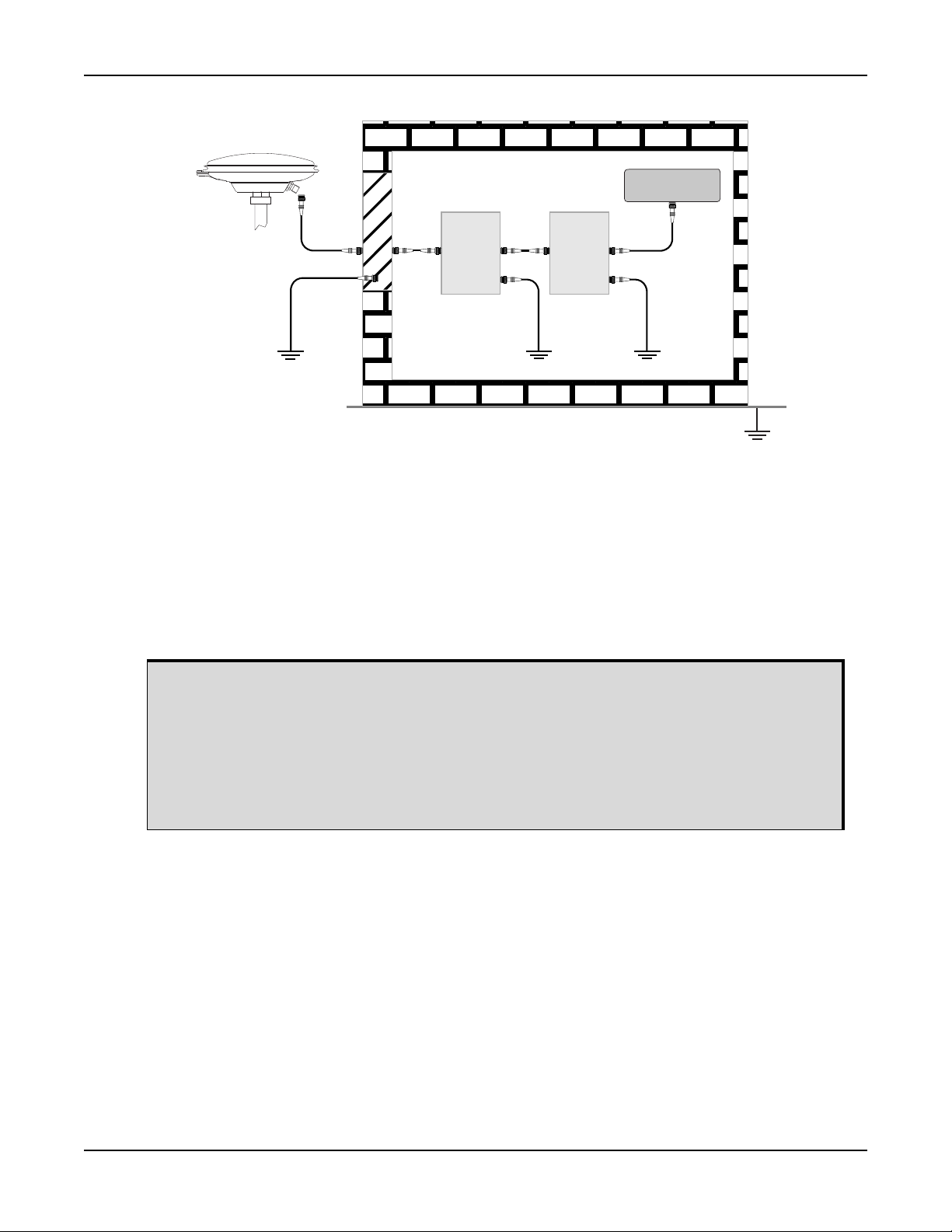
Ref # Description Ref # Description
6
12
5
555
4
3
1 Primary lightning protection device 4 GNSS Receiver
2 Secondary lightning protection device 5 To ground
3 External antenna 6
Acceptable choices for earth grounds, for central buildings, are:
• Grounded interior metal cold water pipe within five feet (1.5 m) of the point where it
enters the building
• Grounded metallic service raceway
• Grounded electrical service equipment enclosure
• Eight-foot grounding rod driven into the ground (only if bonded to the central
building ground by #6, or heavier, bonding wire)
These installation instructions are the minimum requirements for receiver and antenna installations. Where
applicable, follow the electrical codes for the country of installation. Examples of country codes include:
• USA National Electrical Code (NFPA 70)
• Canada Canadian Electrical Code (CSA C22)
• UK British Standards Institute (BSI 7671)
Grounding plate or grounding point at the
building’s entrance
OEM6 Family Installation and Operation User Manual Rev 12 16

Conventions
The following conventions are used in this manual:
Information that supplements or clarifies text.
A caution that actions, operation or configuration may lead to incorrect or improper use of
the hardware.
A warning that actions, operation or configuration may result in regulatory noncompliance,
safety issues or equipment damage.
Specific to the OEM615 card
Specific to the OEM617 card
Specific to the OEM617D card
Specific to the OEM628 card
Specific to the OEM638 card
Specific to the FlexPak6 enclosure
Specific to the FlexPak6D enclosure
OEM6 Family Installation and Operation User Manual Rev 12 17

Customer Support
NovAtel Knowledge Base
If a technical issue occurs, visit the NovAtel support website at www.novatel.com/support/ and search for
general information about GNSS and other technologies, information about NovAtel hardware, software,
installation and operation issues.
Before Contacting Customer Support
Before contacting NovAtel Customer Support about a firmware problem, perform the following steps:
1. Log the following data to a file on a computer for 15 minutes:
RXSTATUSB once
RAWEPHEMB onchanged
RANGEB ontime 1
BESTPOSB ontime 1
RXCONFIGA once
VERSIONA once
2. Send the data file to NovAtel Customer Support, using either the NovAtel FTP site at ftp://ftp.novatel.ca/
or through the support@novatel.com
3. Also issue a FRESET command to the receiver to clear any unknown settings.
Note how the receiver is configured before sending the FRESET command by logging
RXCONFIGA once to recall settings. The FRESET command erases all user settings and
performs a factory reset.
If a hardware problem is encountered, send a list of the troubleshooting steps taken and the results.
e-mail address.
Contact Information
Log a support request with NovAtel Customer Support using one of the following methods:
Log a Case and Search Knowledge:
Website: www.novatel.com/support
Log a Case, Search Knowledge and View Your Case History: (login access required)
Web Portal: https://novatelsupport.force.com/community/login
E-mail:
support@novatel.com
Telephone:
U.S. and Canada: 1-800-NOVATEL (1-800-668-2835)
International: +1-403-295-4900
OEM6 Family Installation and Operation User Manual Rev 12 18

Chapter 1 Introduction
1.1 Overview of the OEM6 Family of Cards and Enclosures
The OEM6 family offers Global Navigation Satellite System (GNSS) receivers and integrated L-Band
capability. The OEM6 family supports existing and planned GPS, GLONASS, QZSS, BeiDou and Galileo
frequencies and is capable of full code and Real-Time Kinematic (RTK) positioning. OEM6 boards are
designed for flexibility of integration and configuration. NovAtel enclosures are compact and lightweight and
easy to integrate.
For further information about OEM6 receiver boards, refer to the product brochures at www.novatel.com/
products/gnss-receivers/.
1.1.1 OEM6 Family Receiver Cards
• OEM615 - refer to OEM615 Receiver on page 20 for details
• OEM617 - refer to OEM617 Receiver on page 20 for details
• OEM617D - refer to OEM617D Receiver on page 21 for details
• OEM628 - refer to OEM628 Receiver on page 21 for details
• OEM638 - refer to OEM638 Receiver on page 22 for details
1.1.2 OEM6 Receiver Enclosure
• FlexPak6 - refer to FlexPak6 on page 26 for details
• FlexPak6D - refer to FlexPak6D on page 27 for details
1.2 Related Documents and Information
After the OEM6 hardware is operational, the OEM6 Family Firmware and Reference Manual (OM-20000129)
becomes the primary source for command and log information. Each receiver has a specific set of features,
such as L-Band or GLONASS support, so some commands and logs may not be supported by your model.
Refer also to our web site www.novatel.com/support/
This manual does not cover OEM6 service and repair. Contact a local NovAtel dealer for service or repair
inquiries (refer to Customer Support on page 18 for contact details).
for the latest documentation.
OEM6 Family Installation and Operation User Manual Rev 12 19

Introduction Chapter 1
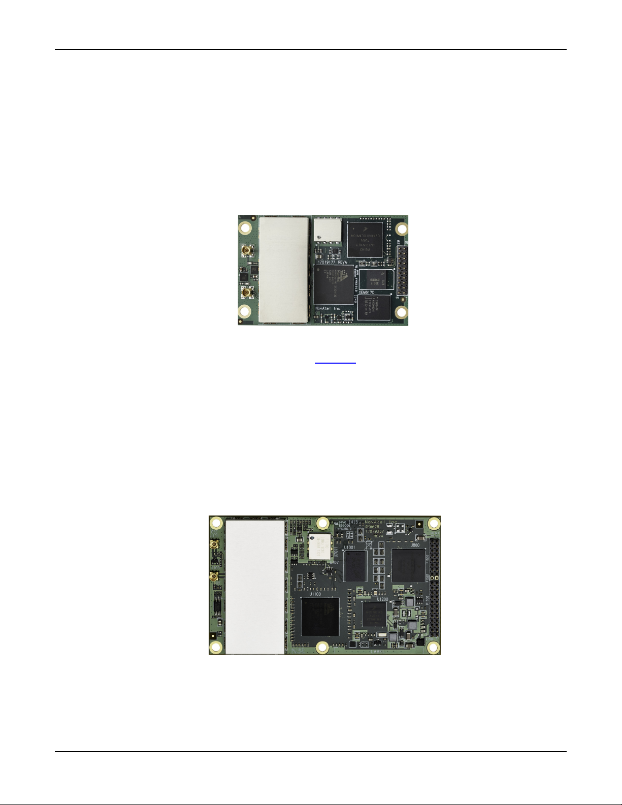
1.2.1 OEM615 Receiver
The OEM615 has the same form and fit as NovAtel’s OEMV-1™ receivers, with the following features:
• Dual-frequency: L1, L2 and L2C for GPS and
GLONASS
• Multi-constellation: E1 for Galileo and B1 for
BeiDou
• UART LVTTL and USB communications port • GLIDE, RTK and ALIGN positioning options
Figure 1: OEM615 Receiver Board
OEM615 technical specifications are provided in Appendix A, OEM615 Technical Specifications on page 113.
• Smallest form factor
• Low power consumption
1.2.2 OEM617 Receiver
The OEM617 has the same form and fit as NovAtel’s OEMV-1™ receivers, with the following features:
• Dual-frequency: L1, L2 and L2C for GPS
and GLONASS
• Multi-constellation: E1 and E5b for Galileo
and B1 and B2 for BeiDou
• UART LVTTL and USB communications
port
• Smallest form factor
• Low power consumption
• GLIDE, RTK and ALIGN positioning options
Figure 2: OEM617 Receiver Board
OEM617 technical specifications are provided in Appendix B, OEM617 Technical Specifications on
page 125.
OEM6 Family Installation and Operation User Manual Rev 12 20
Introduction Chapter 1
1.2.3 OEM617D Receiver
The OEM617D has the same form and fit as NovAtel’s OEMV-1™ receivers, with the following features:
• Dual antenna, dual-frequency: L1, L2 and
L2C for GPS and GLONASS
• Multi-constellation: E1 and E5b for Galileo
and B1 and B2 for BeiDou
• Primary and Secondary antennas, UART
LVTTL and USB communications port
Figure 3: OEM617D Receiver Board
OEM617D technical specifications are provided in Appendix C, OEM617D Technical Specifications on
page 135. Also refer to the NovAtel application note APN-071
available on NovAtel’s OEM617D receiver.
• Smallest form factor
• Low power consumption
• RTK with precise ALIGN heading+pitch/roll
for an explanation of the different models
1.2.4 OEM628 Receiver
The OEM628 has the same form and fit as NovAtel’s OEMV-2™ receivers, with the following features:
• Triple-frequency/Multi-constellation: GPS L1,
L2, L2C, L5; GLONASS L1, L2, L2C; Galileo
E1, E5a, E5b, AltBOC; BeiDou B1, B2
• L-Band capability (TerraStar) • GLIDE, RTK and ALIGN positioning options
Figure 4: OEM628 Receiver Board
OEM628 technical specifications are provided in Appendix D, OEM628 Technical Specifications on
page 145.
• UART RS-232/RS-422 and LVTTL, USB and
Ethernet communications port
OEM6 Family Installation and Operation User Manual Rev 12 21
Introduction Chapter 1
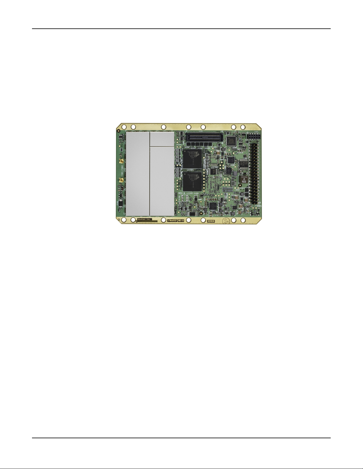
1.2.5 OEM638 Receiver
The OEM638 has the same form and fit as NovAtel’s OEMV-3™ receivers, with the following features:
• Triple-frequency/Multi-constellation: GPS L1,
L2, L2C, L5; GLONASS L1, L2, L2C; Galileo
E1, E5a, E5b, AltBOC; BeiDou B1, B2
• L-Band capability (TerraStar) • Onboard data storage
• GLIDE, RTK and ALIGN positioning options
Figure 5: OEM638 Receiver Board
• UART RS-232/RS-422 and LVTTL, USB
device and host and Ethernet
communications port
OEM638 technical specifications are provided in Appendix E, OEM638 Technical Specifications on
page 162.
OEM6 Family Installation and Operation User Manual Rev 12 22
Introduction Chapter 1
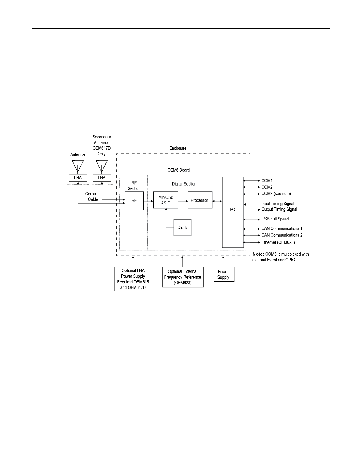
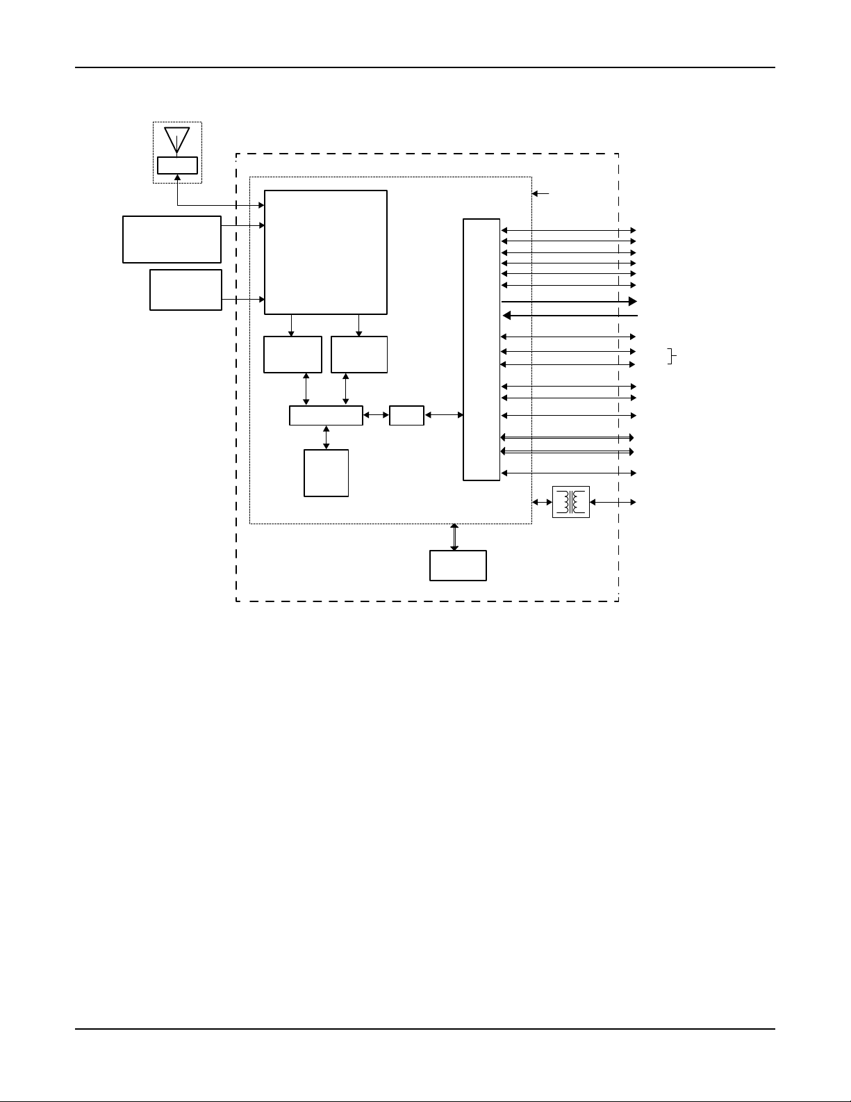
1.3 OEM6 Receiver System Overview
In addition to the NovAtel OEM6 receiver board, an OEM6 receiver system requires the following:
• Enclosure and wiring harness
• Power supply
• Data communications equipment
• GNSS antenna (and optional Low Noise Amplifier (LNA) power supply)
The overall OEM6 receiver systems are illustrated in Figure 6, OEM615, OEM617, OEM617D and OEM628
Receiver System on page 23, Figure 7, OEM638 Receiver System on page 24 and described in the sections
that follow.
Figure 6: OEM615, OEM617, OEM617D and OEM628 Receiver System
OEM6 Family Installation and Operation User Manual Rev 12 23
Introduction Chapter 1
Antenna
LNA
RF
Section
MINOS6
ASIC
MINOS6
ASIC
OEM638 Board
Enclosure
Processor
FPGA
SD Card or
BT/Wi-Fi
Onboard
Storage
(4 GB)
I/O
Optional LNA
Power Supply
Optional External
Frequency Reference
(OEM638)
Power Supply
(3.3 V
or 4.5 V-36 V)
SDIO Interface
COM1
COM2
COM3
COM4
COM5
COM6/IMU
Transceiver
Transceiver
Transceiver
Event Output (x7)
Event Input (x4)
USB0 Device (High Speed)
USB1
Host Only
(High Speed)
USB2
CAN Communications 1
CAN Communications 2
User IO (x22)
General Purpose
Analog Input
10/100
Ethernet
SPI Interface (x2)
Magnetics
I2C (or IIC) Interface (x2)
Figure 7: OEM638 Receiver System
1.3.1 OEM6 Family Card
1.3.2 Enclosure
OEM6 Family Installation and Operation User Manual Rev 12 24
NovAtel’s OEM6 family cards consist of a Radio Frequency (RF) section and a digital section.
Radio Frequency (RF) Section
The receiver obtains filtered, amplified GNSS signals from the antenna. The RF section down converts the
incoming RF signals to Intermediate Frequency (IF) signals which are processed by the digital section. The
RF section also supplies power to the active antenna LNA through the coaxial cable. The RF section has
been designed to reject common sources of interference.
Digital Section
The heart of the digital section is NovAtel’s MINOS6 ASIC (Application Specific Integrated Circuit). The digital
section digitizes and processes the IF signals to obtain a GNSS solution (position, velocity and time). It also
processes the system I/O, shown in Figure 6, OEM615, OEM617, OEM617D and OEM628 Receiver System
on page 23 and Figure 7, OEM638 Receiver System on page 24.
An enclosure is necessary to protect the OEM6 family card from environmental extremes and high levels of
RF interference.
Introduction Chapter 1
1.3.3 GNSS Antenna
The antenna converts electromagnetic signals transmitted by GNSS satellites into electrical signals that can
be used by the receiver. An active GNSS antenna is normally required for optimal receiver performance.
NovAtel’s active GNSS antennas provide precise phase centers and robust enclosures (refer to our web site
www.novatel.com/antennas
).
Optional LNA Power Supply
The receiver can supply power for the antenna LNA. If the antenna is not compatible with the OEM6 power
supply, an external LNA supply may be required. See Antenna LNA Power on page 77 for more information.
An external LNA power supply is required for the OEM615, OEM617 and OEM617D cards.
1.3.4 Power Supply
A power supply capable of delivering the minimum receiver operating voltage and power is required. See
Table 3, Voltage Input Requirement for OEM6 Family Cards on page 31 and Appendix A, OEM615 Technical
Specifications on page 113, Appendix C, OEM617D Technical Specifications on page 135, Appendix D,
OEM628 Technical Specifications on page 145 and Appendix E, OEM638 Technical Specifications on
page 162 for details.
1.3.5 Optional External Frequency Reference
When applications require greater precision than the OEM628 or OEM638 internal clock, connect the
OEM628 or OEM638 to an external high stability oscillator. See External Oscillator on page 76 for more
information.
The OEM615, OEM617 and OEM617D do not offer external oscillator capabilities.
1.3.6 Data Communications Equipment
A computer or other data communications device is necessary to communicate with the receiver and to
receive and store the data that the receiver provides.
1.3.7 Onboard Memory
The OEM638 has 4 gigabytes of onboard memory for data logging. Refer to Logging and Retrieving Data
Overview on page 78 for details.
OEM6 Family Installation and Operation User Manual Rev 12 25
Introduction Chapter 1
1.4 OEM6 Enclosures
The OEM628 and OEM617D card are also housed in enclosures to provide a complete receiver solution.
The FlexPak6 and FlexPak6D enclosures offer protection against environmental conditions, in addition to the
easy to use interface to the card’s data, power and status signals.
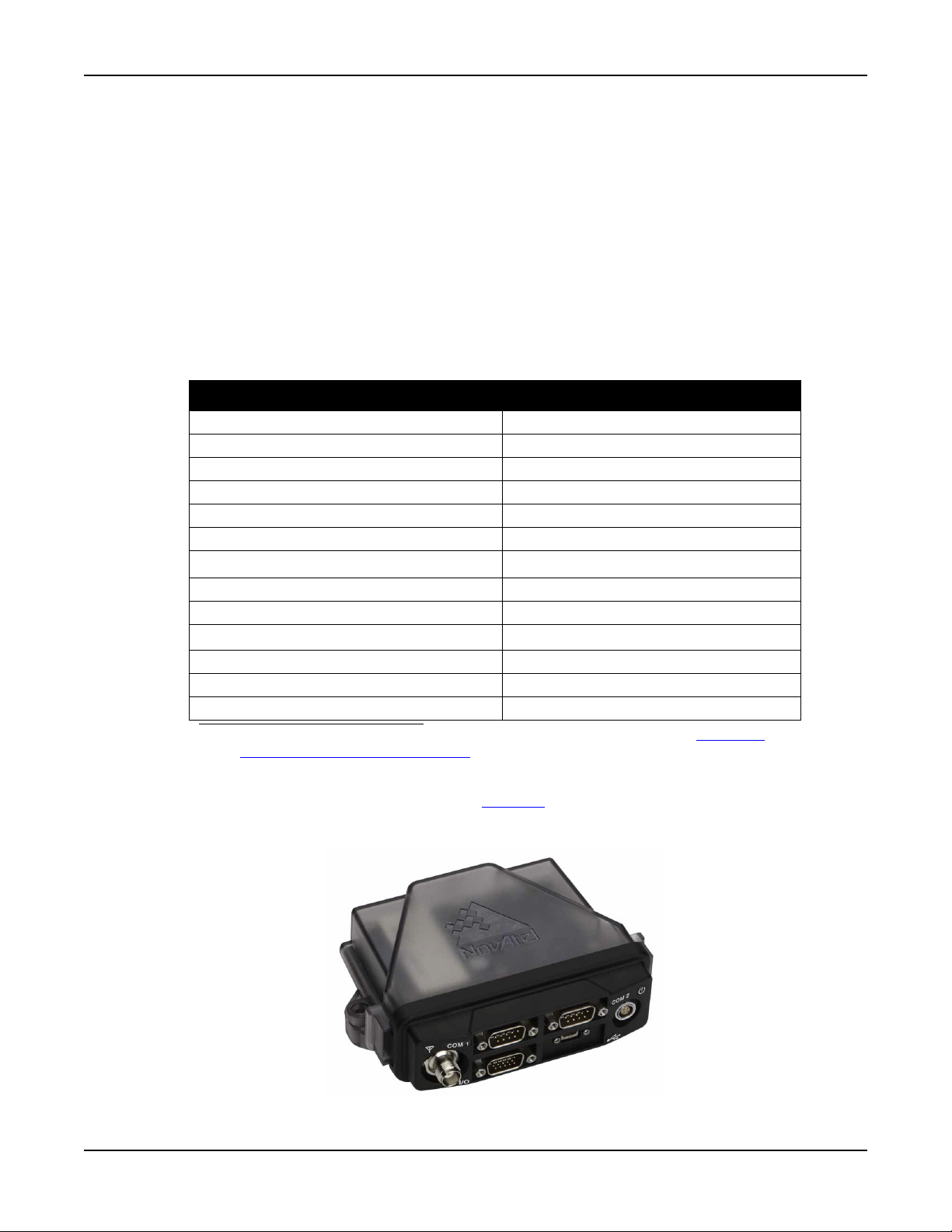
1.4.1 FlexPak6
NovAtel's FlexPak6 uses the OEM628 card to deliver centimeter level positioning in a compact, lightweight
enclosure. The FlexPak6 provides scalable high precision positioning with Ethernet, serial, USB and CAN
bus interfaces as well as an Application Program Interface (API) option for supporting custom applications.
The FlexPak6 receiver is capable of tracking GPS L1/L2/L2C/L5, GLONASS L1/L2, BeiDou B1/B2 and
Galileo E1/E5a/E5b/Alt-BOC signals. Table 1, FlexPak6 Features on page 26 lists the features available on
the FlexPak6.
Table 1: FlexPak6 Features
Feature FlexPak6
OEM card OEM628
Serial ports 2 DB9 connectors
Antenna connector Single TNC
USB 2.0 Yes
Ethernet, CAN, I/O, Strobe port DB-HD15 connector
Input (DC) voltage +6 to +36 V
NovAtel CORRECT™ with PPP
a
GPS + GLONASS positioning Yes
GLIDE™ Yes
®
ALIGN
NovAtel CORRECT™ with RTK Yes
RAIM Yes
NTRIP Yes
Yes
Yes
a. A TerraStar subscription is required which is available direct from NovAtel www.nova-
tel.com/products/novatel-correct-ppp/.
For technical specifications on the FlexPak6, see Appendix F, FlexPak6 Technical Specifications on
page 190. Also refer to the NovAtel application note APN-071
for an explanation of the different models
available on NovAtel’s FlexPak7D receiver.
Figure 8: FlexPak6
OEM6 Family Installation and Operation User Manual Rev 12 26
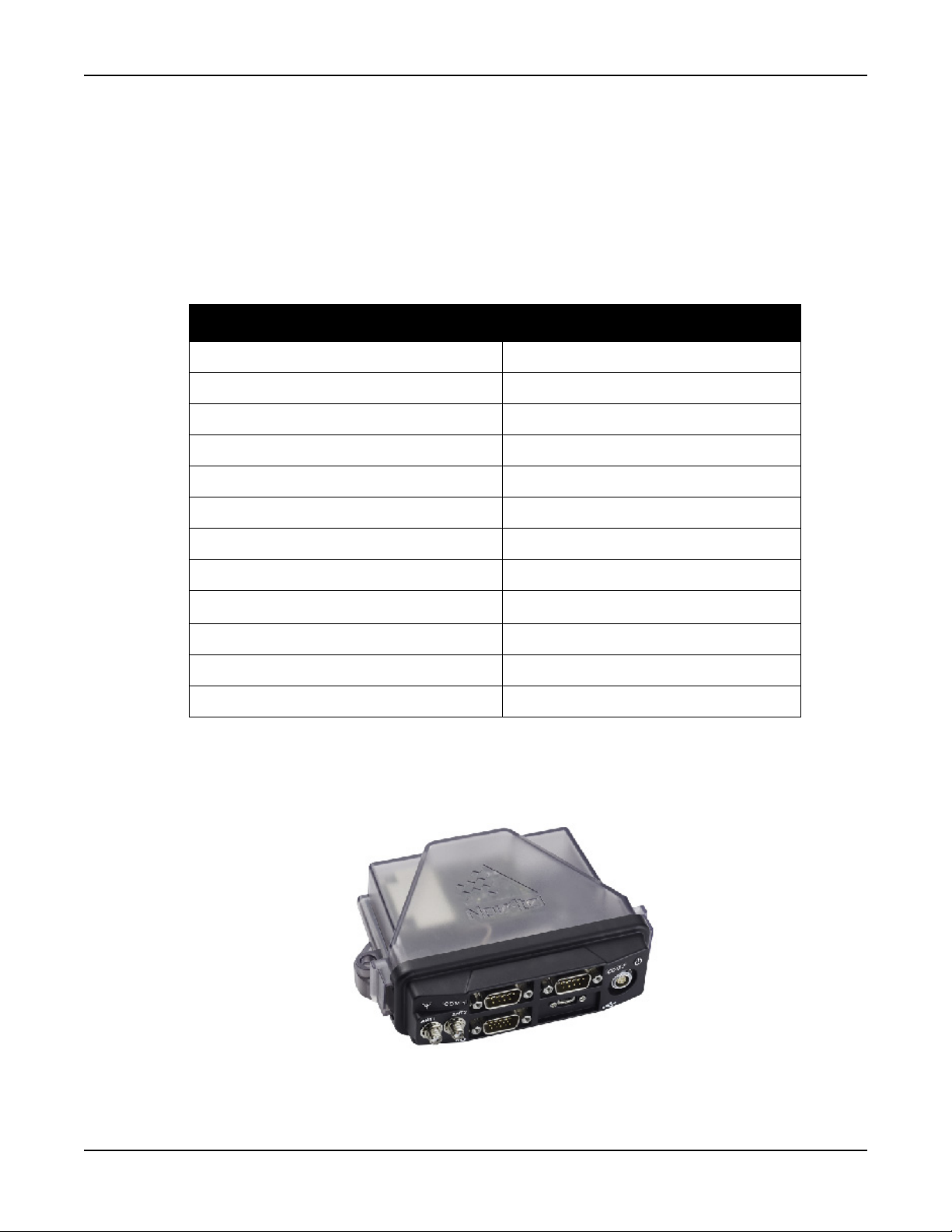
Introduction Chapter 1
1.4.2 FlexPak6D
NovAtel's compact and lightweight FlexPak6D is scalable to offer sub-metre to centimetre level positioning.
Options include RTK for centimetre level real-time positioning, ALIGN
positioning, GLIDE™ for decimetre level pass-to-pass accuracy and RAIM for increased GNSS pseudorange
integrity.The FlexPak6D provides scalable high precision positioning with serial and USB interfaces as well
as an Application Program Interface (API) option for supporting custom applications. The FlexPak6D receiver
is capable of tracking GPS L1/L2/L2C, GLONASS L1/L2, BeiDou B1/B2 and Galileo E1 signals. Ta bl e 2,
FlexPak6D Features on page 27 lists the features available on the FlexPak6D.
Table 2: FlexPak6D Features
Feature FlexPak6D
OEM card OEM617D
Serial ports 2 DB9 connectors
Dual antenna 2 SMA connectors
USB 2.0 Yes
I/O, Strobe port DB-HD15 connector
Input (DC) voltage +6 to +36 V
®
for precise heading and relative
GPS + GLONASS positioning Yes
GLIDE™ Yes
ALIGN
®
Yes
NovAtel CORRECT™ with RTK Yes
RAIM Yes
NTRIP No
For technical specifications on the FlexPak6D, see Appendix G, FlexPak6D Technical Specifications on
page 194.
Figure 9: FlexPak6D
OEM6 Family Installation and Operation User Manual Rev 12 27
Chapter 2 Installation OEM6 Family Cards
This chapter provides instructions and guidelines for checking the contents of the shipping box, installing the
NovAtel PC utilities on a computer, integrating a NovAtel receiver into a GNSS receiver system similar to that
described in Section 1.3, OEM6 Receiver System Overview on page 23.
Refer to Chapter 3, Installation FlexPak6 & FlexPak6D Enclosures on page 44 for installation
instructions.
2.1 Shipping Box
The following items are provided with the OEM6 cards:
• OEM6 family receiver card
• OEM6 Family Receivers Quick Start Guide
2.2 Additional Equipment Required
For the receiver to perform optimally, the following additional equipment is required:
• Interface for power, communications and other signals
• Enclosure to protect against the environment
• GNSS antenna (for a list of NovAtel GNSS antennas refer to our web site www.novatel.com/
antennas)
• Coaxial cable (and interconnect adapter cable, as necessary)
• Data communication equipment capable of serial, USB or Ethernet communication
• Serial, USB or Ethernet data cable (if one is not included with the receiver)
• Power supply
• Power cable (if one is not included with the receiver)
• Optional NovAtel OEM6 Development Kit (01018849) (contact www.novatel.com/support
instructions on using the OEM6 Development Kit with the OEM638 receiver card).
When the OEM6 family receiver is installed in a permanent location, it should be protected by a
lightning protection device according to local building codes (refer to the Lightning Protection
Installation and Grounding Procedure on page 15).
Emissions
OEM6 family products have been designed and tested to meet regulatory emission limits.
Emission levels may be higher for OEM6 family card level operation than for integrated
enclosure level products, like the FlexPak6, using an OEM6 family card.
The OEM615, 628 and 638 cards emission status is Class B. The OEM617 and OEM617D is
Class A.
for
OEM6 Family Installation and Operation User Manual Rev 12 28

Installation OEM6 Family Cards Chapter 2
2.3 Selecting a GNSS Antenna
An active antenna with an LNA is required to boost the power of the incoming signal to compensate for the
line loss between the antenna and the receiver.
NovAtel offers a variety of antennas, including single and dual-frequency, triple-band and wide-band
reference GNSS antennas (refer to our web site: www.novatel.com/antennas
antennas). All antennas include band pass filtering and an LNA. The GNSS antenna chosen depends on the
particular application. Each model offers exceptional phase center stability and a significant measure of
immunity against multipath interference. Each antenna has an environmentally sealed radome and all meet
the European Union’s Restriction of Hazardous Substances (RoHS) and Waste Electrical and Electronic
Equipment (WEEE).
2.3.1 Choosing a Coaxial Cable
To select a coaxial cable for the application, consult the NovAtel application note APN-003 RF
Equipment Selection and Installation available at www.novatel.com/support/. Also refer to this
application note if the application requires the use of cable longer than 30 m.
An appropriate coaxial cable matches the impedances of the antenna and receiver (50 ohms) and has a line
loss not exceeding 10.0 dB
may not meet performance specifications. NovAtel offers several coaxial cables to meet GNSS antenna
interconnection requirements, including:
. If the limit is exceeded, excessive signal degradation may occur and the receiver
for details of available
• 5, 15 and 30 m antenna cable with TNC connectors on both ends (NovAtel part numbers GPS-C006,
GPS-C016 and GPS-C032)
A conversion is required between the OEM617D, OEM628 and OEM638’s MMCX connector or
the OEM615’s and OEM617 MCX connector and the female TNC connector on NovAtel’s
GNSS antennas.
NovAtel recommends using high quality coaxial cables because an impedance mismatch is
possible when using lower quality cables and this produces reflections in the cable that
increases signal loss. Although other high quality antenna cables can be used, the performance
specifications of the OEM6 family receivers are warranted only when used with NovAtel
supplied accessories.
2.3.2 Mounting the GNSS Antenna
After the OEM6 family card is installed in an enclosure, the antenna can be mounted and connected. The
GNSS receiver is designed to operate with any of the NovAtel single, dual and triple-frequency GNSS
antenna models. See Section 2.3, Selecting a GNSS Antenna on page 29
When installing the antenna:
• Choose an antenna location with a clear view of the sky so each satellite above the horizon can be
tracked without obstruction. For more information on RF signal propagation and multipath, refer to
the NovAtel application note APN-008 Discussions on RF Signal Propagation and Multipath
www.novatel.com/support/
• Mount the antenna on a secure, stable structure capable of safe operation in the specific
environment.
.
for more information.
at
OEM6 Family Installation and Operation User Manual Rev 12 29
Installation OEM6 Family Cards Chapter 2
2.3.3 Connecting the Antenna to the Receiver
Connect the antenna to the receiver using a high quality coaxial cable (as discussed in Section 2.3.1,
Choosing a Coaxial Cable on page 29).
For the OEM615, an interconnect adapter cable is required to convert the end of the coaxial
cable to the card’s MCX female RF input connector. The RF connector location for the OEM615
is shown in Figure 10, OEM615 Connector and Indicator Locations on page 35. A user supplied
LNA_PWR supply is internally regulated to 5 VDC and sent to the center pin of the MCX RF
connector to power an external antenna (the return is the outer conductor of the coax).
The antenna port is capable of providing up to 100 mA to a connected antenna (based on a 6 V
input supply). Higher input voltages should follow the derating curve (refer to Appendix A,
OEM615 Technical Specifications on page 113 for antenna details). The typical current draw for
a NovAtel antenna is less than 40 mA.
For the OEM617, an interconnect adapter cable is required to convert the end of the coaxial
cable to the card’s MCX female RF input connector. The RF connector location for the OEM617
is shown in Figure 11, OEM617 Connector and Indicator Locations on page 36. A user supplied
LNA_PWR supply is internally regulated to 5 VDC and sent to the center pin of the MCX RF
connector to power an external antenna (the return is the outer conductor of the coax).
The antenna port is capable of providing up to 200 mA to a connected antenna (based on a 6 V
input supply). Higher input voltages should follow the derating curve (refer to Appendix B,
OEM617 Technical Specifications on page 125 for antenna details). The typical current draw for
a NovAtel antenna is less than 40 mA.
For the OEM617D, an interconnect adapter cable is required to convert the end of the coaxial
cable to the card’s MMCX female RF input connector. The RF connector location for the
OEM617D is shown in Figure 12, OEM617D Connectors and Indicators on page 36. A user
supplied LNA_PWR supply is internally regulated to 5 VDC and sent to the center pin of the
MMCX RF connector to power an external antenna (the return is the outer conductor of the coax).
The antenna ports are capable of providing up to 100 mA to a connected antenna (based on a 6
V input supply). Higher input voltages should follow the derating curve (refer to Appendix C,
OEM617D Technical Specifications on page 135 for antenna details). The typical current draw
for a NovAtel antenna is less than 40 mA.
For the OEM628, an interconnect adapter cable is required to convert the end of the coaxial
cable to the card’s MMCX female RF input connector. The RF connector location for the
OEM628 is shown in Figure 13, OEM628 Connector and Indicator Locations on page 37.
The OEM628 has an internal 5 V LNA_PWR supply, limited to 100 mA.
Refer to Appendix D, OEM628 Technical Specifications on page 145 for details.
For the OEM638, an interconnect adapter cable is required to convert the end of the coaxial
cable to the card’s MMCX female RF input connector. The RF connector location for the
OEM638 is shown in Figure 14, OEM638 Connector and Indicator Locations on page 38.
The OEM638 has an internal 5 V LNA_PWR supply (limited to 200 mA) and an optional LNA
supply that goes to the antenna with no regulation or derating.
Refer to Appendix E, OEM638 Technical Specifications on page 162 for details.
Refer to Antenna LNA Power on page 77 for antenna power requirements.
OEM6 Family Installation and Operation User Manual Rev 12 30
 Loading...