

Novatel OEM6, OEM7 Integration Manual

OEM6 to OEM7
Integration Guide
OM-20000164 v1 February 2017

OEM6 to OEM7 Integration Guide
OEM6 to OEM7 Integration Guide
Publication Number: OM-20000164
Revision Level: v1
Revision Date: February 2017
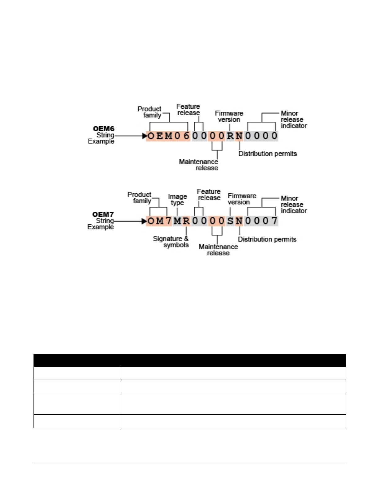
Firmware Version: 7.200 / OM7MR0200RN0000
Proprietary Notice
Information in this document is subject to change without notice and does not represent a commitment on the part of NovAtel Inc. The information contained within this manual is believed to
be true and correct at the time of publication.
NovAtel is a registered trademarks of NovAtel Inc.
OEM7, OEM719, OEM729 and OEM7700 are trademarks of NovAtel Inc.
All other brand names are trademarks of their respective holders.
© Copyright 2017 NovAtel Inc. All rights reserved. Unpublished rights reserved under International copyright laws.
OEM6 to OEM7 Integration Guide v1 2

OEM6 to OEM7 Integration Guide
Table of Contents
OEM6 to OEM7 Integration Guide
OEM6 to OEM7 Integration Guide 2
Proprietary Notice 2
Customer Support
NovAtel Knowledge Base 6
Before Contacting Customer Support 6
Contact Information 6
Chapter 1 New for OEM7
Chapter 2 New for OEM7 – Firmware
2.1 Firmware Version Naming 9
2.2 New for OEM7 – Commands 9
2.2.1 Replaced Commands 9
2.2.2 Revised Commands 10
2.2.3 Deleted Commands 13
2.2.4 New Commands 13
2.2.5 CANCONFIG 16
2.2.6 CCOMCONFIG 18
2.2.7 COMCONTROL 21
2.2.8 CONNECTIMU 24
2.2.9 EXTERNALPVAS 26
2.2.10 FORCEGLOL2CODE 30
2.2.11 FORCEGPSL2CODE 32
2.2.12 INSCALIBRATE 34
2.2.13 INSSEED 36
2.2.14 ITBANDPASSCONFIG 38
2.2.15 ITFRONTENDMODE 40
2.2.16 ITINTERFERENCEDETECT 42
2.2.17 ITPROGFILTCONFIG 44
2.2.18 ITSPECTRALANALYSIS 46
2.2.19 J1939CONFIG 50
2.2.20 NMEAFORMAT 52
2.2.21 NVMUSERDATA 55
2.2.22 PGNCONFIG 56
2.2.23 PPPBASICCONVERGEDCRITERIA 57
2.2.24 PPPDYNAMICSEED 58
2.2.25 PPPRESET 60
2.2.26 REFERENCESTATIONTIMEOUT 61
2.2.27 RTKPORTMODE 62
2.2.28 RTKRESET 64
2.2.29 SAVEUSBCONFIG 65
2.2.30 SETINSPROFILE 66
2.2.31 SETINSROTATION 67
2.2.32 SETINSTRANSLATION 70
2.2.33 SETSEARCHTYPE 73
2.2.34 USBCONFIG 74
2.3 New for OEM7 – Logs 76
2.3.1 Replaced Logs 76
2.3.2 Revised Logs 76
2.3.3 Deleted Logs 79
OEM6 to OEM7 Integration Guide v1 3

OEM6 to OEM7 Integration Guide
2.3.4 New Logs 80
2.3.5 HWMONITOR 82
2.3.6 INSATTX 86
2.3.7 INSCALSTATUS 91
2.3.8 INSCONFIG 93
2.3.9 INSSTDEV 96
2.3.10 INSSTDEVS 98
2.3.11 INSUPDATESTATUS 100
2.3.12 ITBANDPASSBANK 102
2.3.13 ITFILTTABLE 104
2.3.14 ITPROGFILTBANK 106
2.3.15 ITPSDFINAL 109
2.3.16 J1939STATUS 112
2.3.17 LBANDRAWFRAME 114
2.3.18 MODELFEATURES 116
2.3.19 RANGECMP4 120
2.3.20 RTKASSISTSTATUS 132
2.3.21 RXSTATUS 134
2.3.22 SAFEMODESTATUS 146
2.4 New for OEM7 – SPAN 149
2.4.1 Translational Offsets 149
2.4.2 Rotational Offsets 149
2.4.3 INS Profiles 150
2.4.4 INSSeed 150
2.4.5 Multi-Line Body to Vehicle Calibration 150
2.4.6 KVH1725 and KVH1750 Baud Rate Conversion 151
2.4.7 INS Profiles 152
2.4.8 Multi-Line Body to Vehicle Frame Rotation Calibration Routine 153
2.4.9 INSSeed / Fast INS Initialization 155
Saving 155
Use at Boot-up 155
Alignment Type: Bits 26-28 156
NVM Seed Status: Bits 29-31 156
Chapter 3 New for OEM7 – Hardware
3.1 Physical changes 157
3.1.1 Shielding 157
3.1.2 Mounting 157
3.1.3 Weight 158
3.2 Electrical changes 158
3.2.1 COM Port Data Rate 158
3.2.2 Power Supply 158
3.2.3 Input and Output lines 159
3.2.4 LNA Power 159
3.3 Environmental changes 160
3.3.1 Thermal dissipation 160
3.3.2 Vibration 160
3.4 Interference 160
3.4.1 Interference from Co-Located LNA 161
3.5 Receiver Card Interface Examples 163
3.5.1 EVENT_IN, EVENT_OUT and PPS Signal Protection 163
3.5.2 Position Valid (PV) LED Driver 165
3.5.3 Communication Ports 166
3.5.4 CAN Controller Ports 167
3.5.5 USB Interface 168
OEM6 to OEM7 Integration Guide v1 4

OEM6 to OEM7 Integration Guide
3.5.6 Ethernet Port 170
Chapter 4 Receiver Technical Specifications
4.1 OEM719 Technical Specifications 174
4.1.1 OEM719 Performance Specifications 175
4.1.2 OEM719 Mechanical Specifications 177
4.1.3 OEM719 Electrical and Environmental Specifications 184
4.1.4 OEM719 Data Communication Specifications 186
4.1.5 OEM719 Strobe Specifications 188
4.1.6 OEM719 Interface Connector 190
4.2 OEM729 Technical Specifications 194
4.2.1 OEM729 Performance Specifications 195
4.2.2 OEM729 Mechanical Specifications 197
4.2.3 OEM729 Electrical and Environmental Specifications 200
4.2.4 OEM729 Data Communication Specifications 202
4.2.5 OEM729 Strobe Specifications 204
4.2.6 OEM729 Interface Connectors 206
4.3 OEM7700 Technical Specifications 214
4.3.1 OEM7700 Performance Specifications 215
4.3.2 OEM7700 Mechanical Specifications 217
4.3.3 OEM7700 Electrical and Environmental Specifications 220
4.3.4 OEM7700 Data Communication Specifications 222
4.3.5 OEM7700 Strobe Specifications 224
4.3.6 OEM7700 Interface Connector 226
OEM6 to OEM7 Integration Guide v1 5

Customer Support
Customer Support
NovAtel Knowledge Base
If you have a technical issue, visit the NovAtel Support page at www.novatel.com/support.
Through the Support page, you can contact Customer Support, find papers and tutorials or download current manuals and the latest firmware.
Before Contacting Customer Support
Before you contact NovAtel Customer Support about a software problem, perform the following
steps:
If logging data over an RS-232 serial cable, ensure that the configured baud rate can support the data bandwidth (see SERIALCONFIG command). NovAtel recommends a min-
imum suggested baud rate of 115200 bps.
1.
Log the following data to a file on your computer for 15 minutes:
RXSTATUSB once
RAWEPHEMB onchanged
GLORAWEPHEMB onchanged
BESTPOSB ontime 1
RANGEB ontime 1
RXCONFIGA once
VERSIONA once
For SPAN systems, include the following logs in the file created on your computer:
RAWIMUSXB onnew
INSUPDATESTATUSB onnew
INSPVAXB ontime 1
INSCONFIGA once
2.
Send the data file to NovAtel Customer Support: support@novatel.com
3.
You can also issue a FRESET command to the receiver to clear any unknown settings.
The FRESET command will erase all user settings. You should know your configuration
(by requesting the RXCONFIGA log) and be able to reconfigure the receiver before you
send the FRESET command.
If you are having a hardware problem, send a list of the troubleshooting steps taken and the results.
Contact Information
Log a support request with NovAtel Customer Support using one of the following methods:
Log a Case and Search Knowledge:
OEM6 to OEM7 Integration Guide v1 6

Customer Support
Website: www.novatel.com/support
Log a Case, Search Knowledge and View Your Case History: (login access required)
Web Portal: https://novatelsupport.force.com/community/login
E-mail:
support@novatel.com
Telephone:
U.S. and Canada:1-800-NOVATEL (1-800-668-2835)
International:+1-403-295-4900
OEM6 to OEM7 Integration Guide v1 7

Chapter 1 New for OEM7
When upgrading from an OEM6 receiver to an OEM7 receiver, there are several hardware and
software differences that must be accounted for in the system design.
These differences are described in the following chapters:
l
New for OEM7 – Firmware on page9
l
New for OEM7 – Hardware on page157
l
Receiver Technical Specifications on page173
OEM6 to OEM7 Integration Guide v1 8
Chapter 2 New for OEM7 – Firmware
This chapter describes the new commands, logs, features and functionality available on OEM7
receivers.
2.1 Firmware Version Naming
For information about the fields in the firmware version, refer to the VERSION log.
2.2 New for OEM7 – Commands
The following sections describe the command changes between OEM6 and OEM7.
2.2.1 Replaced Commands
The following table lists the OEM6 commands that have been obsoleted and the commands that
replace them in OEM7.
Table 1: Replaced Commands in OEM7
OEM6 OEM7
ASSIGNLBAND Use the existing ASSIGNLBANDBEAM command
ASSIGNLBAND2 Use the existing ASSIGNLBANDBEAM command
BASEANTENNAMODEL
COM Use the existing SERIALCONFIG command
Use the existing BASEANTENNAPCO command and
BASEANTENNAPCV command
OEM6 to OEM7 Integration Guide v1 9

Chapter 2 New for OEM7 – Firmware
OEM6 OEM7
COMCONFIG
EXTHDGOFFSET Use the new SETINSROTATION command (see page 67)
GIMBALSPANROTATION Use the new SETINSROTATION command (see page 67)
INSWHEELUPDATE Use the existing SETINSUPDATE command
INSZUPTCONTROL Use the existing SETINSUPDATE command
LEVERARMCALIBRATE Use the new INSCALIBRATE command (see page 34)
PDPVELOCITYOUT Use the existing BESTVELTYPE command
RVBCALIBRATE Use the new INSCALIBRATE command (see page 34)
SETGIMBALORIENTATION Use the new SETINSROTATION command (see page 67)
SETIMUORIENTATION Use the new SETINSROTATION command (see page 67)
SETIMUTOANTOFFSET Use the new SETINSTRANSLATION command (see page 70)
SETIMUTOANTOFFSET2 Use the new SETINSTRANSLATION command (see page 70)
SETIMUTOEXTOFFSET Use the new SETINSTRANSLATION command (see page 70)
SETIMUTOGIMBALOFFSET Use the new SETINSTRANSLATION command (see page 70)
Use the existing SERIALCONFIG command, INTERFACEMODE
command and ECHO command
SETINSOFFSET Use the new SETINSTRANSLATION command (see page 70)
SETINITATTITUDE Use the existing SETINITAZIMUTH command
SETINSOFFSETS
SETINSROTATION
SETMARK1OFFSET
SETMARK2OFFSET
SETMARK3OFFSET
SETMARK4OFFSET
VEHICLEBODYROTATION Use the new SETINSROTATION command (see page 67)
Use the new SETINSROTATION command on page67 and
SETINSTRANSLATION command on page70
The existing SETINSROTATION command (Message ID1796) has been
renamed SETINSROTATION_LEGACY, but retains the Message IDof
1796.
A new SETINSROTATION command (see page 67) (Message ID1921)
has been added. This new command has enhanced capability and is the
recommend command to use.
Use the new SETINSROTATION command on page67 and
SETINSTRANSLATION command on page70
2.2.2 Revised Commands
Revised commands are listed in the following table.
OEM6 to OEM7 Integration Guide v1 10

Chapter 2 New for OEM7 – Firmware
Table 2: Revised Commands in OEM7
OEM6 OEM7
3V3 option removed
ANTENNAPOWER
ASSIGN,
ASSIGNALL,
LOCKOUT,
SBASCONTROL,
The OEM7 tracks SBAS PRNs 120-158 and 183-187.
The OEM6 tracked 120-138 and 183-187
TRACKSV,
UNLOCKOUT
If a short circuit or other problem causes an overload of the current supplied to the antenna, the receiver hardware shuts down
the power supplied to the antenna. To restore power, power
cycle the receiver. The Receiver Status word, available in the
RXSTATUS log (see page 134), provides more information
about the cause of the problem.
ASSIGNLBANDBEAM
AUTH
COMCONTROL
This command now supports multiple L-Band channels.
The Frequency field is entered only in Hz.
New options were added for the State parameter
ASCII Binary Description
ERASE_
TABLE
CLEAN_
TABLE
7
8 Remove all invalid auth codes from the system
Erase all auth codes from the system. Requires a
special auth code to prevent against accidental
erasing
Special auth code for the ERASE_TABLE case:
PW5W2B,WW5TM9,WW2PCZ,WW3M4H,WW4HPG,ERASE_AUTH
Special auth code for the CLEAN_TABLE case:
4DR69H,G369W8,34MNJJ,5NHXCJ,GW7C75,CLEAN_AUTH
The COM ports available have changed to reflect the OEM7 receivers.
See the COMCONTROL command on page21
OEM6 to OEM7 Integration Guide v1 11

Chapter 2 New for OEM7 – Firmware
OEM6 OEM7
Added the EPSON G320 IMU.
Removed the Litef LCI-1 IMU.
CONNECTIMU
ETHCONFIG
EXTERNALPVAS
FRESET
INTERFACEMODE
For the IMU Type parameter, the ASCII values for IMU no longer use the
"IMU_" prefix. However, the legacy ASCIIvalues that contain the "IMU_"
prefix are still supported. The binary IMU type values have not changed.
See the CONNECTIMU command on page24
Ethernet interface hardware now automatically connects properly to the
other physical device
The format of several of the options in this command have been changed
from Double to Float.
See the EXTERNALPVAS command on page26
Added new FRESET targets.
Binary ASCII Description
10 USERDATA
Resets the user data saved using the
NVMUSERDATA command
82 USBCONFIG Resets the stored USB port settings
Added new Interface Mode options:
Binary ASCII Description
NovAtel binary message with a minimal
49 NOVATELMINBINARY
header.
Only available for CCOM ports.
The default settings for a command can not be checked by logging that
command. A command must be sent to the receiver before logging the
command will produce valid values. Refer to the command description in
this documentation for the default values.
The optional parameters Period, Offset and Hold are only used when the
LOG
Trigger is ONTIME. Previous versions of the firmware accepted (but ignored)
non-zero values for Period and Offset even if the Trigger was not ONTIME.
The firmware on OEM7 receivers will reject such commands and return an
error.
It is especially important that these values are zero when entering a LOG
command in Binary or ASCII format.
POSAVE “state” field no longer optional; default ON. A value must now be entered
SETINITAZIMUTH
OEM6 to OEM7 Integration Guide v1 12
The range for the standard deviation parameter has changed to 1 to 25
degrees.

Chapter 2 New for OEM7 – Firmware
2.2.3 Deleted Commands
The OEM6 commands that are not supported in OEM7 are listed in the following table.
Table 3: Deleted Commands in OEM7
OEM6 OEM7
APPLYVEHICLEBODYROTATION obsolete
ASSIGNLBAND obsolete
ASSIGNLBAND2 obsolete
DGPSEPHEMDELAY obsolete
OMNIUSEGLONASS obsolete
PDPVELOCITYOUT obsolete
RTKCOMMAND obsolete
RTKELEVMASK obsolete
SETCANNAME obsolete
SETRTCM16 obsolete
SETRTCM36 obsolete
SETRTCMRXVERSION obsolete
SETRTCMTXVERSION obsolete
SETWHEELSOURCE obsolete
2.2.4 New Commands
The following table lists the commands added in OEM7.
Table 4: New Commands in OEM7
OEM7 Description
CANCONFIG
CCOMCONFIG
Configures the CAN port parameters
See the CANCONFIG command on page16
Binds a CAN port to a J1939 node configures the CAN protocol
used by the port.
See the CCOMCONFIG command on page18
INSCALIBRATE
OEM6 to OEM7 Integration Guide v1 13
Initiates the calibration of INS offsets
See the INSCALIBRATE command on page34

Chapter 2 New for OEM7 – Firmware
OEM7 Description
INSSEED
Enables or disables saving and restoring the last known SPAN
solution
See the INSSEED command on page36
ITBANDPASSCONFIG
ITFRONTENDMODE
ITINTERFERENCEDETECT
ITPROGFILTCONFIG
ITSPECTRALANALYSIS
J1939CONFIG
NMEAFORMAT
NVMUSERDATA
Configures a bandpass filter on the receiver
See the ITBANDPASSCONFIG command on page38
Configures the front end mode for each RF path
See the ITFRONTENDMODE command on page40
Enables and configures interference detection
See the ITINTERFERENCEDETECT command on page42
Configures filtering on the receiver
See the ITPROGFILTCONFIG command on page44
Enables and configures spectral analysis on the receiver
See the ITSPECTRALANALYSIS command on page46
Configures the CAN J1939 network-level parameters
See the J1939CONFIG command on page50
Customizes the NMEA output
See the NMEAFORMAT command on page52
Writes the data provided to NVM
See the NVMUSERDATA command on page55
PGNCONFIG
PPPBASICCONVERGEDCRITERIA
PPPDYNAMICSEED
PPPRESET
Configures the PGNs of the proprietary NMEA 2000 fast-packet
messages
See the PGNCONFIG command on page56
Sets the convergence threshold for lower accuracy PPP
solutions.
See the PPPBASICCONVERGEDCRITERIA command on
page57
Seed the PPP filter in any platform motion state
See the PPPDYNAMICSEED command on page58
Resets the PPPfilter.
See the PPPRESET command on page60
OEM6 to OEM7 Integration Guide v1 14

Chapter 2 New for OEM7 – Firmware
OEM7 Description
REFERENCESTATIONTIMEOUT
RTKPORTMODE
RTKRESET
SAVEUSBCONFIG
SETINSPROFILE
SETINSROTATION
SETINSTRANSLATION
Sets a timeout for removing previously stored base stations
See the REFERENCESTATIONTIMEOUT command on page61
Assigns a port on the rover receiver for the RTK and ALIGN
information being received
See the RTKPORTMODE command on page62
Resets the RTK filter.
See the RTKRESET command on page64
Saves the USB port configuration.
See the SAVEUSBCONFIG command on page65
Set the filter behavior to optimize the output for a specific
environment
See the SETINSPROFILE command on page66
Specifies the rotational offsets between the IMU frame and
other reference frames, such as the vehicle frame or an ALIGN
baseline
see the SETINSROTATION command on page67
Specifies the translational offsets between the IMU frame and
other reference frames, including GNSS antennas or the desired
output frame
SETSEARCHTYPE
USBCONFIG
See the SETINSTRANSLATION command on page70
Specifies the search type used by the receiver for signal
acquisition.
See the SETSEARCHTYPE command on page73
Configures the operating mode and speed of the USBport.
See the USBCONFIG command on page74
OEM6 to OEM7 Integration Guide v1 15

Chapter 2 New for OEM7 – Firmware
2.2.5 CANCONFIG
Configure CAN ports
Platform:OEM729, OEM719, OEM7700
Use the CANCONFIG command to configure the hardware parameters of the CAN ports.
Message ID: 884
Abbreviated ASCII Syntax:
CANCONFIG port switch [speed]
Factory Default:
CANCONFIG CAN1 OFF 250K
CANCONFIG CAN2 OFF 250K
ASCII Example:
CANCONFIG CAN1 OFF 500K
Field Field Type
1
2 port
3 switch
4 speed
CANCONFIG
header
The CAN port must be set to OFF (using CANCONFIG <port> OFF) before the port speed
can be changed.
ASCII
Value
- -
CAN1 1
CAN2 2
ON 1
OFF 0
See Table 5: CAN
Port Speed below
Binary
Value
Table 5: CAN Port Speed
Description Format
Command header. See
Messages for more
information.
Physical CAN port ID Enum 4 H
Sets the port to be On or
Off the CAN bus
Physical CANport speed
(bits per second)
(default = 250K
- H 0
Enum 4 H+4
Enum 4 H+8
Binary
Bytes
Binary
Offset
ASCII Value Binary Value
10K 0
20K 1
OEM6 to OEM7 Integration Guide v1 16

Chapter 2 New for OEM7 – Firmware
ASCII Value Binary Value
50K 2
100K 3
125K 4
250K 5
500K 6
1M 7
OEM6 to OEM7 Integration Guide v1 17

Chapter 2 New for OEM7 – Firmware
2.2.6 CCOMCONFIG
Configure the CAN COM port
Platform:OEM729, OEM719, OEM7700
Bind a CAN communication port to a J1939 node (see J1939CONFIG command on page50) and
specify the CAN protocol, PGN, priority and address for messages transmitted and received over
the CCOM port.
Message ID: 1902
Abbreviated ASCII Syntax:
CCOMCONFIG port node protocol [pgn [priority [address]]]
Factory Default:
CCOMCONFIG ccom1 node1 1939 61184 7 fe
CCOMCONFIG ccom2 node2 J1939 61184 7 fe
CCOMCONFIG ccom3 node1 J1939 126720 7 fe
CCOMCONFIG ccom4 none none 0 0 0
CCOMCONFIG ccom5 none none 0 0 0
CCOMCONFIG ccom6 none none 0 0 0
ASCII Example :
ccomconfig ccom1 j1939 1792 6 1b
Field Field Type
1
2 port
CCOMCONFIG
Header
ASCII
Value
- -
CCOM1 38
CCOM2 39
CCOM3 40
CCOM4 41
CCOM5 42
Binary
Value
Description Format
Command header. See
Messages for more
information.
Name of CCOM port Enum 4 H
- H 0
Binary
Bytes
Binary
Offset
CCOM6 43
NODE1 1
3 node
NODE2 2
OEM6 to OEM7 Integration Guide v1 18
The J1939 node to use.
This binds a CCOM port to
the CAN NAME/address
associated with the node.
Enum 4 H+4

Chapter 2 New for OEM7 – Firmware
Field Field Type
ASCII
Value
See Table 6:
4 protocol
CAN Protocol on
the next page
5 pgn 0 - 131071
6 priority 0-7
Binary
Value
Description Format
CAN transport protocol to
use
Any valid PGN as defined
by the J1939 protocol.
All messages transmitted
over this CCOM port will
contain this PGN value.
Only messages with this
PGN will be received on
this CCOM port
Note: This value is
ignored if the protocol is
NMEA2000.
Default CAN message
priority for transmitted
messages. (Priority 0 is
the highest priority)
Note: This value is
ignored if the protocol is
NMEA2000 or ISO15765.
Binary
Bytes
Binary
Offset
Enum 4 H+8
Ulong 4 H+12
Uchar 1 H+16
7 address 00 – FF
00 – FD:
Transmit and receive
messages to/from this
address only
FE:
Transmit and receive
message to/from the
address of the first
message received
FF:
Broadcast messages and
receive messages from
all addresses.
Note: This value is
ignored if the protocol is
NMEA2000 or ISO15765.
Hex 1 H+17
OEM6 to OEM7 Integration Guide v1 19

Chapter 2 New for OEM7 – Firmware
Binary ASCII Description
2 J1939 J1939 single packet
3 NMEA2000 NMEA2000 (single packet, multi-packet, fast packet)
4 ISO15765 ISO 15765-2 transport protocol
5 ISO11783 ISO 11783 transport protocol
Table 6: CAN Protocol
OEM6 to OEM7 Integration Guide v1 20

Chapter 2 New for OEM7 – Firmware
2.2.7 COMCONTROL
Controls the serial port hardware control lines
Platform:OEM729, OEM719, OEM7700
This command is used to control the hardware control lines of the serial communication (COM)
ports. The TOGGLEPPS mode of this command is typically used to supply a timing signal to a
host PC computer by using the RTS and DTR lines. The accuracy of controlling the COM control
signals is better than 900 ms. The other modes are typically used to control custom peripheral
devices.
1.
If handshaking is disabled, any of these modes can be used without affecting regular
serial communications through the selected COM port. However, if handshaking is
enabled, it may conflict with handshaking of the selected COM port, causing unexpected results.
2.
The PULSEPPSLOW control type cannot be issued for a TX signal.
3.
Only PULSEPPSHIGH, FORCEHIGH and FORCELOW control types can be used for a TX
signal.
Message ID: 431
Abbreviated ASCII Syntax:
COMCONTROL [port] [signal] [control]
Factory Default:
COMCONTROL COM1 RTS DEFAULT
COMCONTROL COM2 RTS DEFAULT
COMCONTROL COM3 RTS DEFAULT
COMCONTROL COM4 RTS DEFAULT
COMCONTROL COM5 RTS DEFAULT
ASCII Example 1:
SERIALCONFIG COM1 9600 N 8 1 N (to disable handshaking)
COMCONTROL COM1 RTS FORCELOW
ASCII Example 2:
COMCONTROL COM1 RTS TOGGLEPPS
COMCONTROL COM2 RTS TOGGLEPPS
COMCONTROL COM3 RTS TOGGLEPPS
ASCII Example 3:
To set a break condition on COM1:
COMCONTROL COM1 TX FORCELOW
A break condition remains in effect until it is cleared. To clear a break condition on AUX:
COMCONTROL COM1 TX DEFAULT
OEM6 to OEM7 Integration Guide v1 21

Chapter 2 New for OEM7 – Firmware
or
COMCONTROL COM1 TX FORCEHIGH
Field
Field
Type
COM
1
CONTROL
header
2 port
3 signal
ASCII Value
Binary
Value
- -
COM1 1
COM2 2
COM3 3
COM4 19
COM5 31
RTS 0
TX 2
Description Format
Binary
Bytes
Binary
Command header.
See Messages for
- H 0
more information.
Serial port to control. Enum 4 H
COM signal to control.
The controllable COM
signals are RTS, DTR
and TX. (Default =
RTS)
Enum 4 H+4DTR 1
See also Table 7: Tx,
DTR and RTS
Availability on the
next page
Offset
OEM6 to OEM7 Integration Guide v1 22

Chapter 2 New for OEM7 – Firmware
Field
Field
Type
4 control
ASCII Value
Binary
DEFAULT 0
FORCEHIGH 1
FORCELOW 2
TOGGLE 3
TOGGLEPPS 4
Value
Description Format
Disables this
command and returns
the COM signal to its
default state (Default)
Immediately forces
the signal high
Immediately forces
the signal low
Immediately toggles
the current sate of the
signal
Toggles the state of
the selected signal
within 900 μs after
each 1PPS event. The
state change of the
signal lags the 1PPS
by an average value
of 450 μs. The delay
of each pulse varies
by a uniformly
random amount less
than 900 μs
Binary
Bytes
Binary
Offset
Enum 4 H+8
Pulses the line low at
PULSEPPSLOW 5
a 1PPS event and to
high 1 ms after it. Not
for TX
Pulses the line high
PULSEPPSHIGH 6
for 1 ms at the time
of a 1PPS event
Table 7: Tx, DTR and RTS Availability
Tx Available On DTR Available On RTS Available On
OEM719 COM1, COM2 N/A N/A
OEM729 COM1, COM2, COM3 N/A COM1 and COM2
OEM7700 COM1, COM2, COM3, COM4, COM5 N/A COM1 and COM2
OEM6 to OEM7 Integration Guide v1 23

Chapter 2 New for OEM7 – Firmware
2.2.8 CONNECTIMU
Connects an IMU to a Port
Platform:OEM729, OEM719, OEM7700
Use this command to specify the type of IMU connected to the receiver and the receiver port
used by the IMU.
Message ID: 1428
Abbreviated ASCII Syntax:
CONNECTIMU IMUPort IMUType
Abbreviated ASCII Example:
CONNECTIMU COM2 LN200
Field Field Type
1
2 IMUPort
CONNECTIMU
header
1
3 IMUType
SPI, COM4 and COM5 are available only on the OEM7700.
ASCII
Value
Binary
Value
Description
Command header. See
- -
Messages for more
information.
COM1 1 IMU Port is COM port 1
COM2 2 IMU Port is COM port 2
COM3 3 IMU Port is COM port 3
SPI 7
IMUPort is the SPIport
(OEM7700 only)
COM4 19 IMUPort is COM port 4
COM5 31 IMU Port is COM port 5
See Table 8: IMU
Type on the next
IMU Type Enum 4 H+4
page
Binary
Format
Binary
Bytes
Binary
- H 0
Enum 4 H
Offset
1
The IMU-ISA-100C, IMU-FSAS, IMU-HG1900, IMU-LN200, IMU-µIMU, IMU-CPT and IMU-KVH1750 use RS-422
protocol and must be connected to a receiver port that is configured to use RS-422. Refer to the OEM7 Installation
and Operation User Manual (OM-20000168) for information about which receiver ports support RS-422 and
instructions for enabling RS-422.
OEM6 to OEM7 Integration Guide v1 24
Chapter 2 New for OEM7 – Firmware
Binary ASCII Description
0 UNKNOWN Unknown IMU type (default)
1 HG1700_AG11 Honeywell HG1700 AG11
4 HG1700_AG17 Honeywell HG1700 AG17
5 HG1900_CA29 Honeywell HG1900 CA29
8 LN200 Litton LN-200
11 HG1700_AG58 Honeywell HG1700 AG58
12 HG1700_AG62 Honeywell HG1700 AG62
13 IMAR_FSAS iMAR iIMU-FSAS
16 KVH_COTS KVH IMU-CPT
20 HG1930_AA99 Honeywell HG1930 AA99
26 ISA100C Northrop Grumman Litef ISA-100C
Table 8: IMU Type
27 HG1900_CA50 Honeywell HG1900 CA50
28 HG1930_CA50 Honeywell HG1930 CA50
31 ADIS16488 Analog Devices ADIS16488
32 STIM300 Sensonor STIM300
33 KVH_1750 KVH1750 IMU
34 ISA100 Northrop Grumman Litef ISA-100
41 EPSON_G320 Epson G320
45 KVH-1725 KVH1725 IMU
52 LITEF_MICROIMU Litef µIMU
The IMU Type field also supports the legacy ASCIIvalues that contain the "IMU_" prefix.
For example, LN200 or IMU_LN200.
Values not shown in this table are reserved.
OEM6 to OEM7 Integration Guide v1 25
Chapter 2 New for OEM7 – Firmware
2.2.9 EXTERNALPVAS
Enter PVA Update
Platform:OEM729, OEM719, OEM7700
This command should only be used by advanced users of GNSS/INS.
The standard deviations entered using this command must be representative of actual
input error.
The EXTERNALPVAS command uses a short header if the command is entered in ASCII
or Binary.
This command allows a user to provide full position, velocity and attitude updates, in any combination, to the INS. The user can also provide height or attitude only updates, along with Zero
Velocity Updates (ZUPTs). These position and velocity updates are entered in local level frame
or ECEF.
The default input frame is ECEF. Updates are entered in ECEF unless Local Level is specified using the OptionsMask parameter.
Message ID: 1463
Abbreviated ASCII Syntax:
EXTERNALPVAS Position1 Position2 Position3 Velocity1 Velocity2 Velocity3
Attitude1 Attitude2 Attitude3 PosStdDev1 PosStdDev2 PosStdDev3 VelStdDev1
VelStdDev2 VelStdDev3 AttStdDev1 AttStdDev2 AttStdDev3 UpdateMask
OptionsMask
Abbreviated ASCII Example:
EXTERNALPVAS 51.13495816 -114.03232307 1064.5895 -10.4502 0.2485 -0.09598
1.3152366 -3.6474718 179.5885212 0.01 0.01 0.01 0.01 0.01 0.01 0.1 0.1 0.1
C020 1
Field Field Type
1
EXTERNALPVAS
header
ASCII
Value
- -
Binary
Value
Description
Command header. See
Messages for more
information.
Binary
Format
- H 0
Binary
Bytes
Binary
Offset
OEM6 to OEM7 Integration Guide v1 26

Chapter 2 New for OEM7 – Firmware
Field Field Type
2 Position1
3 Position2
4 Position3
5 Velocity1
6 Velocity2
7 Velocity3
ASCII
Value
Binary
Value
Description
Latitude in degrees or
ECEF X-coordinate in
metres
Longitude in degrees or
ECEF Y-coordinate in
metres
Height or ECEF Zcoordinate in metres
North velocity or velocity
along the X-axis in
metres/second
East velocity or velocity
along the Y-axis in
metres/second
Up velocity or velocity
along the Z-axis in
metres/second
Binary
Format
Binary
Bytes
Binary
Offset
Double 8 H
Double 8 H+8
Double 8 H+16
Float 4 H+24
Float 4 H+28
Float 4 H+32
8 Attitude1
9 Attitude2
10 Attitude3
11 PosStdDev1
12 PosStdDev2
13 PosStdDev3
14 VelStdDev1
15 VelStdDev2
Roll in local level in
degrees
Pitch in local level in
degrees
Azimuth in local level in
degrees
Position1 standard
deviation in metres
Position2 standard
deviation in metres
Position3 standard
deviation in metres
Velocity1 standard
deviation in
metres/second
Velocity2 standard
deviation in
metres/second
Float 4 H+36
Float 4 H+40
Float 4 H+44
Float 4 H+48
Float 4 H+52
Float 4 H+56
Float 4 H+60
Float 4 H+64
OEM6 to OEM7 Integration Guide v1 27

Chapter 2 New for OEM7 – Firmware
Field Field Type
16 VelStdDev3
17 AttStdDev1
18 AttStdDev2
19 AttStdDev3
20 UpdateMask
ASCII
Value
Binary
Value
Description
Velocity3 standard
deviation in
metres/second
Attitude1 standard
deviation in degrees
Attitude2 standard
deviation in degrees
Attitude3 standard
deviation in degrees
This mask selects which
updates are applied.
Setting a bit applies the
update and more than
one update can be
applied at one time.
See Table 9:
EXTERNALPVAS Updates
Mask below.
Binary
Format
Binary
Bytes
Binary
Offset
Float 4 H+68
Float 4 H+72
Float 4 H+76
Float 4 H+80
HEX
Ulong
4 H+84
This mask selects the
21 OptionsMask
update options. See
Table 10:
EXTERNALPVAS Options
HEX
Ulong
4 H+88
Mask on the next page.
Table 9: EXTERNALPVAS Updates Mask
Bit Mask Description
0 0x00001 Reserved
1 0x00002 Reserved
2 0x00004 ZUPT Update. No fields required in the EXTERNALPVAS command for this update.
3 0x00008 Reserved
4 0x00010 Reserved
External Position Update.
5 0x00020
This update is entered using Position1 to Position3 in the EXTERNALPVAS
command.
OEM6 to OEM7 Integration Guide v1 28

Chapter 2 New for OEM7 – Firmware
Bit Mask Description
6 0x00040 Reserved
7 0x00080 Reserved
8 0x00100 Reserved
9 0x00200 Reserved
10 0x00400 Reserved
11 0x00800 Reserved
12 0x01000 Reserved
13 0x02000 Reserved
External Velocity Update.
14 0x04000
This update is entered using Velocity1 to Velocity3 in the EXTERNALPVAS
command.
External Attitude Update.
15 0x08000
This update is entered using Attitude1 to Attitude3 in the EXTERNALPVAS
command.
16 0x10000
17 0x20000
External Heading Update.
This update is entered using Attitude3 in the EXTERNALPVAS command.
External Height Update.
This update is entered using Position3 in the EXTERNALPVAS command.
If both the External Position Update and External Height Update bits are set, only the
External Position Update will be applied.
If both the External Attitude Update and External Heading Update bits are set, only the
External Attitude Update will be applied.
Table 10: EXTERNALPVAS Options Mask
Bit Mask Description
If this bit is set, the position and velocity input frame is set to local level.
0 0x1
If cleared, the input frame is ECEF.
If this bit is set, the heading update is set relative.
1 0x2
If cleared, the heading update is absolute.
OEM6 to OEM7 Integration Guide v1 29

Chapter 2 New for OEM7 – Firmware
2.2.10 FORCEGLOL2CODE
Forces receiver to track GLONASS satellite L2 P or L2 C/A code
Platform:OEM729, OEM719, OEM7700
This command is used to force the receiver to track GLONASS satellite L2 P-code or L2 C/A code.
This command has no effect if the channel configuration contains both GLONASS L2 P and L2 C/A
channels.
Message ID: 1217
Abbreviated ASCII Syntax:
FORCEGLOL2CODE L2type
Factory Default:
FORCEGLOL2CODE default
ASCII Example:
FORCEGLOL2CODE p
Field
1
2 L2type
The following table lists which L2 signal is tracked based on the channel configuration and the
setting used for the L2type parameter.
Field
Type
FORCEGLO
L2CODE
header
ASCII
Value
- -
See Table 11:
GLONASS L2 Code
Type below
Binary ASCII Description
1 P L2 P-code or L2 Precise code
2 C L2 C/A code or L2 Coarse/Acquisition code
3 DEFAULT Set to channel default
Binary
Value
Command header. See
Messages for more
information.
GLONASS L2 code type Enum 4 H
Table 11: GLONASS L2 Code Type
Description Format
- H 0
Binary
Bytes
Binary
Offset
OEM6 to OEM7 Integration Guide v1 30
 Loading...