

Novatel ANT-A71GLA4-TW User Manual
ANT-A71GLA4-TW Antenna
The ANT-A71GLA4-TW is an
active GPS antenna that
receives the GPS L1 1575.42
MHz frequency, the GLONASS
L1 1602 – 1626 MHz
frequencies and L-band 1525 –
1560 MHz frequencies.
The ANT-A71GLA4-TW is
aircraft certified for navigation. This guide provides the basic
information you need to install and begin using your new
antenna.
ADDITIONAL EQUIPMENT REQUIRED
• A device with an antenna input port that both receives
the RF signal and provides 2.5 - 24.0 VDC to the
antenna is required for the ANT-A71GLA4-TW. NovAtel
GPS receivers provide the necessary power through
their antenna RF connectors.
• Coaxial cable with a male TNC connector
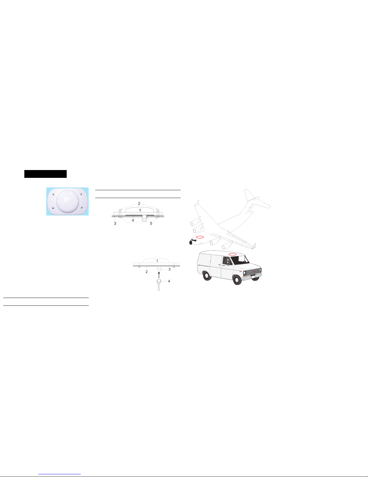
INSTALLING THE ANTENNA
Both the input DC power and the output RF signal use a single
coaxial cable connected to the unit's TNC female connector.
The antenna attaches to a surface with an ARINC-743 bolt
pattern. Four screws pass through the antenna housing.
To install the antenna:
1. Install the supplied o-ring into the groove on the antenna
base.
Note: User-supplied o-ring grease can hold the o-ring in the groove dur-
ing installation.
2. Pre-drill the mounting holes and the connector clearance
hole on the mounting surface. See the Mechanical Drawings
section for mounting pattern details.
3. Use the four supplied mounting screws to attach the antenna
to the mounting surface. The o-ring compresses and creates
a seal between the surface and the antenna.
Note: NovAtel recommends thread-locker (not included) on the
mounting screws.
Ref. # Description Ref.# Description
1 Antenna 4 O-ring
2 Countersink screws 5 Pre-drilled mounting holes
3 Mounting surface
4. Remove the dust cap from the antenna’s TNC connector.
5. Attach the coaxial cable’s male TNC connector to the
antenna’s TNC connector.
6. Attach the other end of the coaxial cable to the antenna input
port on the receiving device. The receiving device must be
equipped to provide power as detailed in the
SPECIFICATIONS section of this guide. All NovAtel GPS
receivers provide the necessary power through the antenna
RF connectors.
This illustration provides examples of where the antenna may be
located on an aircraft or vehicle (not to scale).
ANTENNA CARE
The ANT-A71GLA4-TW is designed to withstand the elements,
including rain, snow and dust. However, to ensure that the
antenna performs optimally, keep the radome clean and brush
off any ice or snow. In addition, ensure the TNC connector
remains clean and dry and replace the dust cap when a cable is
not connected.
USER GUIDE
OM-20000135 Rev 1 April 2012
Ref.# Description
1 Mounted antenna
2 Mounting surface
3 TNC connector
4 Coaxial cable
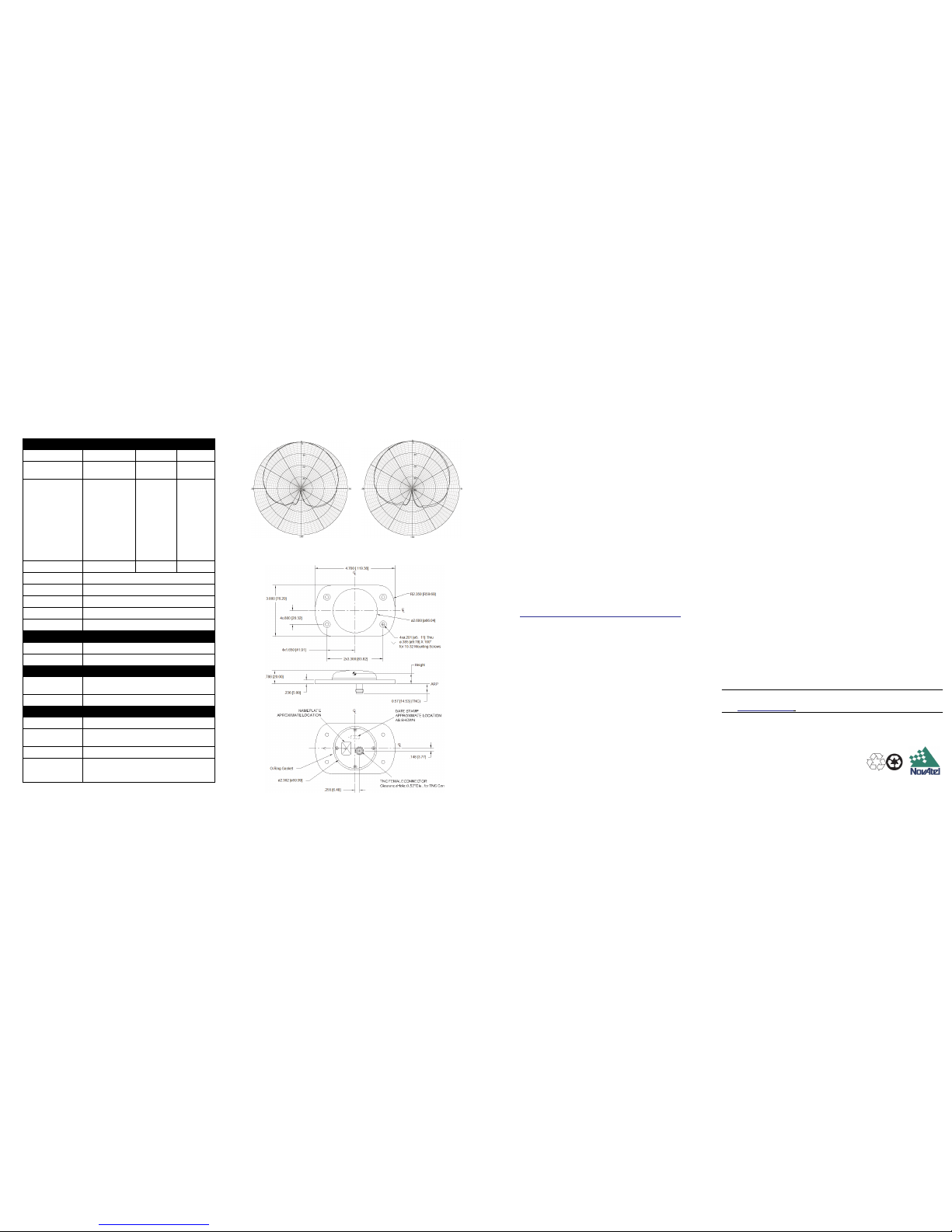
SPECIFICATIONS ELEVATION GAIN PATTERNS
MECHANICAL DRAWINGS
PHASE CENTRE
Please refer to the Mechanical Drawings before reading this
section.
HEIGHT = Vertical phase centre offset from antenna reference
point or antenna reference plane (ARP), see the
MECHANICAL DRAWINGS section of this guide.
For relative offset numbers and phase centre variation (PCV)
tables, please visit the U.S. National Geodetic Survey (NGS)
website at www.ngs.noaa.gov/ANTCAL/.
For absolute offset numbers and to download PCV tables,
please visit the GEO++ website at www.geopp.com.
When using either of the websites mentioned above, look for the
NovAtel listing of your antenna model and its hardware revision.
At the time of print, we are unable to provide typical absolute and
relative offset numbers for the current ANT-A71GLA4-TW
antenna model. Please check our website for updates to this
manual at www.novatel.com/Downloads/docupdates.html and
the websites mentioned above.
If you need any further advice on this matter, please visit our
website at www.novatel.com. Other methods of contacting
Customer Service can be found on the last panel of this guide.
WARRANTY POLICY
NovAtel Inc. warrants that its Global Positioning System (GPS) products are free from
defects in materials and workmanship, subject to the conditions set forth below, for the
following periods of time:
GPSAntenna™ Modules: One (1) Year from date of sale
Cables and Accessories: Ninety (90) Days from date of sale
Date of sale shall mean the date of the invoice to the original customer for the product.
NovAtel's responsibility respecting this warranty is limited solely to product repair at an
authorized NovAtel location only. Determination of repair will be made by NovAtel personnel
or by technical personnel expressly authorized by NovAtel for this purpose.
The foregoing warranties do not extend to
(i) nonconformities, defects or errors in the products due to accident, abuse, misuse or negligent use of the products or use in other than a normal and customary manner, environmental
conditions not conforming to NovAtel’s specifications, or failure to follow prescribed installation, operating and maintenance procedures, (ii) defects, errors or nonconformities in the
products due to modifications, alterations, additions or changes not made in accordance with
NovAtel’s specifications or authorized by NovAtel, (iii) normal wear and tear, (iv) damage
cause by force of nature or act of any third person, (v) shipping damage; or (vi)service or
repair of product by the dealer without prior written consent from NovAtel.
In addition, the foregoing warranties shall not apply to products designated by NovAtel as
beta site test samples, experimental, developmental, preproduction, sample, incomplete or
out of specification products or to returned products if the original identification marks have
been removed or altered.
The warranties and remedies are exclusive and all other warranties, express or implied,
written or oral, including the implied warranties of merchantability or fitness for any particular
purpose are excluded.
NovAtel shall not be liable for any loss, damage or expense arising directly or indirectly out of
the purchase, installation, operation, use or licensing or products or services. In no event
shall NovAtel be liable for special, indirect, incidental or consequential damages of any kind
or nature due to any cause.
There are no user-serviceable parts in the GPSAntenna and no maintenance is required. If
the unit is faulty, replace with another unit and return the faulty unit to NovAtel Inc. You must
obtain a RETURN MATERIAL AUTHORIZATION (RMA) number by calling NovAtel
Customer Service at 1-800-NOVATEL (U.S. and Canada only) or 403-295-4900 before shipping any product to NovAtel or a dealer. Once you have obtained an RMA number, you will
be advised of proper shipping procedures to return any defective product. When returning
any product to NovAtel, please return the defective product in the original packaging to avoid
damage.
Note:Before shipping any material to NovAtel or our Dealer, obtain a Return Material Autho-
rization (RMA) number from the point of purchase. You may also visit our web site
(http://www.novatel.com) and select Support | Repair Request from the side menu.
QUESTIONS OR COMMENTS
If you have any questions or comments regarding your antenna, contact NovAtel Customer
Service using one of methods provided below.
Email: support@novatel.com
Web: www.novatel.com
Phone: 1-800-NOVATEL (U.S. & Canada)
403-295-4900 (International)
Fax: 403-295-4901
© Copyright 2005-2012 NovAtel Inc. All rights reserved.Printed in Canada on recycled paper.
Unpublished rights reserved under international copyright laws. Recyclable.
RF
Band L1 GPS L1 GLONASS L-band
3 dB pass band (typical)
1575.0 ±20 MHz
1614.0 ± 12
MHz
1542.5 ±17.5
MHz
Antenna gain (dBic)
Free 4-foot
Space ground
plane
Free Space Free Space
90° zenith
+5.5 +4.5 >+3.3 >+2.5
10° elevation
-1.2 -1.4 >-3.2 >-4.7
20° elevation
+0.3 +1.4 >-1.6 >-3.0
30° elevation
+1.8 +2.2 >-0.2 >-2.3
60° – 90° elevation
>4.8 >3.8 >+2.5 >+2.0
Beamwidth (dB) 106° 130° 106° 106°
LNA gain 40 dB
Polarization Right-hand circular
Noise figure (typical) 3.0 dB
Nominal impedance 50
VSWR 1.5 : 1
POWER
Input voltage + 2.5 - 24.0 VDC
Current
39 mA
PHYSICAL
Radome
diameter x height
7.62 cm (3.0 inches) W x 11.938 cm (4.70 inches) L
x 2.00 cm (0.788 inches) H
Weight 191 g (6.8 ounces)
ENVIRONMENTAL
Maximum altitude 21,336 m (70,000 ft.)
Operating / storage
temperature
-55° C to +85° C (-67° F to +185° F)
Vibration >30 G
Designed to meet
these standards
FAA TSO-C144, DO-160D, DO-228, MIL-C-5541,
MIL-E-5400, MIL-I-45208A, MIL-STD-810 and SAE
J1455
0
L-Band: Max 2.5 dB
L1 Peak Gain: 5.5 dB
Dimensions are in inches, followed by [mm]
 Loading...