

Novatel ANT-533, ANT-533-N User Manual
ANT-533 and ANT-533-N
The ANT-533 is an active
antenna designed to operate at
the GPS L1 and L2 frequencies,
1575.42 and 1227.60 MHz. This
guide provides the basic information you need to install and begin
using your new antenna.
ADDITIONAL EQUIPMENT
REQUIRED
The equipment listed below is required to set up the ANT-533:
• A mount, such as a range pole, tribrach, or tripod, with a
5/8" x 11 thread
• Coaxial cable with either a TNC connector for the ANT533, or an N-Type connector for the ANT-533-N
• A device with an antenna input port that both receives
the RF signal and provides 2.5 - 24.0 VDC to the
antenna (All NovAtel GPS receivers provide the necessary power through their antenna RF connectors.)
SITE SELECTION GUIDELINES
Before installing the antenna, select a site that as closely as
possible meets the following conditions for optimal performance:
• An unobstructed line-of-sight from horizon to horizon
and at all bearings and elevation angles
• As far as possible from reflective objects, especially
those that are above the antenna and any water bodies,
which can be a strong source of multipath reflections
• If obstructions and reflective surfaces are within 30 m,
ensure the site is as high as possible. Otherwise, mount
the antenna as low as possible.
• For base station locations, ensure the antenna is in a
low-multipath location, close to the ground and away
from reflective objects.
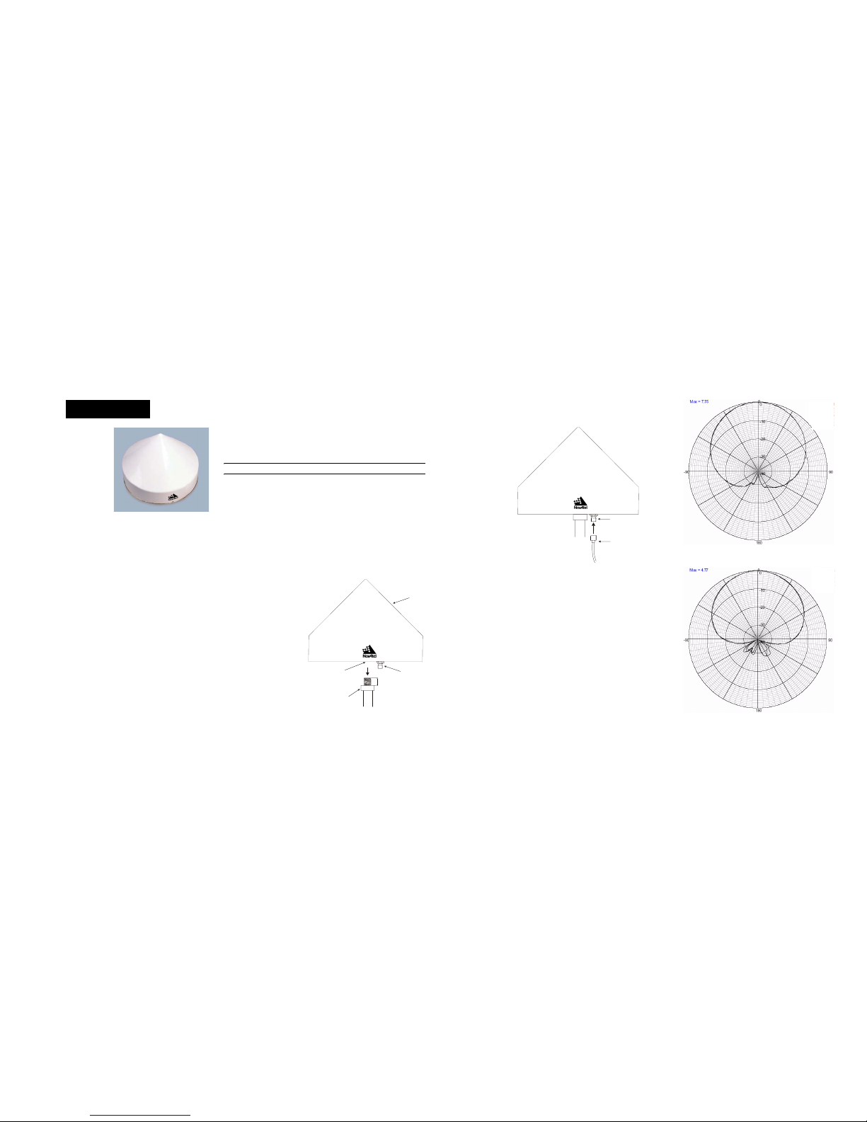
INSTALLING THE ANTENNA
Both the input DC power and the output RF signal flow over a
single coaxial cable that is connected to the unit's TNC, or NType, connector.
The antenna baseplate features an internal thread that accepts a
5/8” x 11 threaded bolt. This allows the antenna to be used on a
tripod.
Caution: Overtightening a bolt into the base may damage the base.
After a site has been selected, install the antenna as follows.
1. Verify that the thread on the mount does not extend more
than 1/2" (12 mm) to ensure the thread is not damaged
when the mount is inserted. If it extends further than 1/2" (12
mm), add two jam nuts to shorten the exposed thread,
ensuring the nuts are well-tightened.
2. Align the mount thread with the internal thread on the bottom
of the antenna and rotate the antenna clockwise until it is
securely screwed to the mount.
Ref. # Description
1 533 with radome
2 Internally threaded
3 TNC or N-Type
connector
4 Thread
5 Jam nuts or flange
6 Mount
3. Remove the dust cap from the antenna’s TNC connector.
4. Attach the male TNC connector of the coaxial cable to the
antenna’s TNC connector.
Ref. # Description
1 TNC or N-Type
connector
2 Coaxial cable
5. Attach the other end of the coaxial cable to the antenna input
port of the receiving device, which must provide power as
detailed in the SPECIFICATIONS section of this guide. All
NovAtel GPS receivers provide the necessary power
through their antenna RF connectors.
ANTENNA CARE
The ANT-533 is designed to withstand the elements, including
rain, snow, and dust. However, to ensure your antenna performs
optimally, keep the radome clean and brush off any ice and
snow. In addition, ensure the TNC, or N-Type, connector
remains clean and dry and replace the dust cap when a cable is
not connected.
L1 ELEVATION GAIN PATTERN
L2 ELEVATION GAIN PATTERN
USER GUIDE
5/8 x 11"
3/8 - 1/2 9 - 12 mm"" ( )
1
2
3
4
5
6
1
2
dB
dB
SPECIFICATIONS MECHANICAL DRAWINGS WARRANTY POLICY
NovAtel Inc. warrants that its Global Positioning System (GPS) products are fre e from
defects in materials and workmanship, subject to the condition s set for th below, for the
following periods of time:
GNSS Antenna™ Modules: One (1) Year
Cables and Accessories: Ninety (90) Days
Date of sale shall mean the date of the invoice to the original customer for the product.
NovAtel's responsibility respecting this warranty is limited solely to product rep air at an
authorized NovAtel location only. Determination of repair will be made by NovAtel
personnel or by technical personnel expressly authorized by NovAtel for this purpose.
The foregoing warranties do not extend to
(i) nonconformities, defects or errors in the products due to accident, abuse, misuse or
negligent use of the products or use in other than a normal and customary manner,
environmental conditions not conforming to NovAtel’s specifications, or failure to follow
prescribed installation, operating and maintenance procedures, (ii) defects, errors or
nonconformities in the products due to modifications, alterations, additions or changes
not made in accordance with NovAtel’s specifications or authorized by NovAtel, (iii)
normal wear and tear, (iv) damage cause by force of nature or act of any third person,
(v) shipping damage; or (vi)service or repair of product by the dealer without prior
written consent from NovAtel.
In addition, the foregoing warranties shall not apply to products designated by NovAtel
as beta site test samples, experimental, developmental, preproduction, sample,
incomplete or out of specification products or to returned products if the original identification marks have been removed or altered.
The warranties and remedies are exclusive and all other warranties, express or
implied, written or oral, including the implied warranties of merch antabili ty or fitness for
any particular purpose are excluded.
NovAtel shall not be liable for any loss, damage or expense arising d irectly or indir ectly
out of the purchase, installation, operation, use or licensing or products or services. In
no event shall NovAtel be liable for special, indirect, incidental or consequential
damages of any kind or nature due to any cause.
There are no user-serviceable parts in the ANT-533 or ANT-533-N and no maintenance is required. If the unit is faulty, replace with another unit and return the faulty
unit to NovAtel Inc. You must obtain a RETURN MATERIAL AUTHORIZATION (RMA)
number by calling NovAtel Customer Service at 1-800-NOVATEL (U.S. and Canada
only) or 403-295-4900 before shipping any product to NovAtel or a dealer. Once you
have obtained an RMA number, you will be advised of proper shipping procedures to
return any defective product. When returning any product to NovAtel, please return the
defective product in the original packaging to avoid damage.
Before shipping any material to NovAtel or Dealer, please obtain a Return Mate-
rial Authorization (RMA) number from the point of purchase. You may also visit
our website (http://www.novatel.com) and select Support | Repair Request from
the side menu.
WEEE NOTICE
If you purchased your ANT-533, or ANT-533-N, in Europe, please return
it to your dealer or supplier at the end of its life. The objectives of the
European Community's environment policy are, in particular, to
preserve, protect and improve the quality of the environment, protect
human health and utilise natural resources prudently and rationally.
Sustainable development advocates the reduction of wasteful consumption of natural resources and the prevention of pollution. Waste electrical and electronic equipment (WEEE) is a regulated area. Where the
generation of waste cannot be avoided, it should be reused or recovered for its material or energy. WEEE products may be recognised by
their wheeled bin label.
RoHS NOTICE
The ANT-533 and ANT-533-N are compliant with the European
Union (EU) Restriction of Hazardous Substances (RoHS) Directive 2002/95/EC.
QUESTIONS OR COMMENTS
If you have any questions or comments regarding your ANT -53 3
or ANT-533-N antenna, please contact NovAtel Customer
Service using one of methods provided below.
Email: support@novatel.com
Web: www.novatel.com
Phone: 1-800-NOVATEL (U.S. & Canada)
403-295-4900 (International)
Fax: 403-295-4901
© Copyright 2006 NovAtel Inc. All rights reserved. Unpublished rights reserved under
international copyright laws. Recyclable.
OM-20000111 Rev 1 November 24, 2006
RF
3 dB pass band (typical)
L1: 1575.42 ±15 MHz
L2: 1227.60 ±15 MHz
Out-of-band rejection (typical) > 40 dBc
Gain at zenith (θ = 90°) (min)
L1: +7.7 dBic L2: +4.7 dBic
Gain roll-off (zenith to horizon) L1:15.2 dB L2: 18 dB
L1/L2 LNA gain (typical) 33/35 ±2 dB
Polarization Right-hand circular
Noise figure (typical) 3.0 dB
Nominal impedance 50 Ω
VSWR ≤ 1.5 : 1
POWER
Input voltage 2.5 - 24.0 VDC
Current (typical) 35 mA
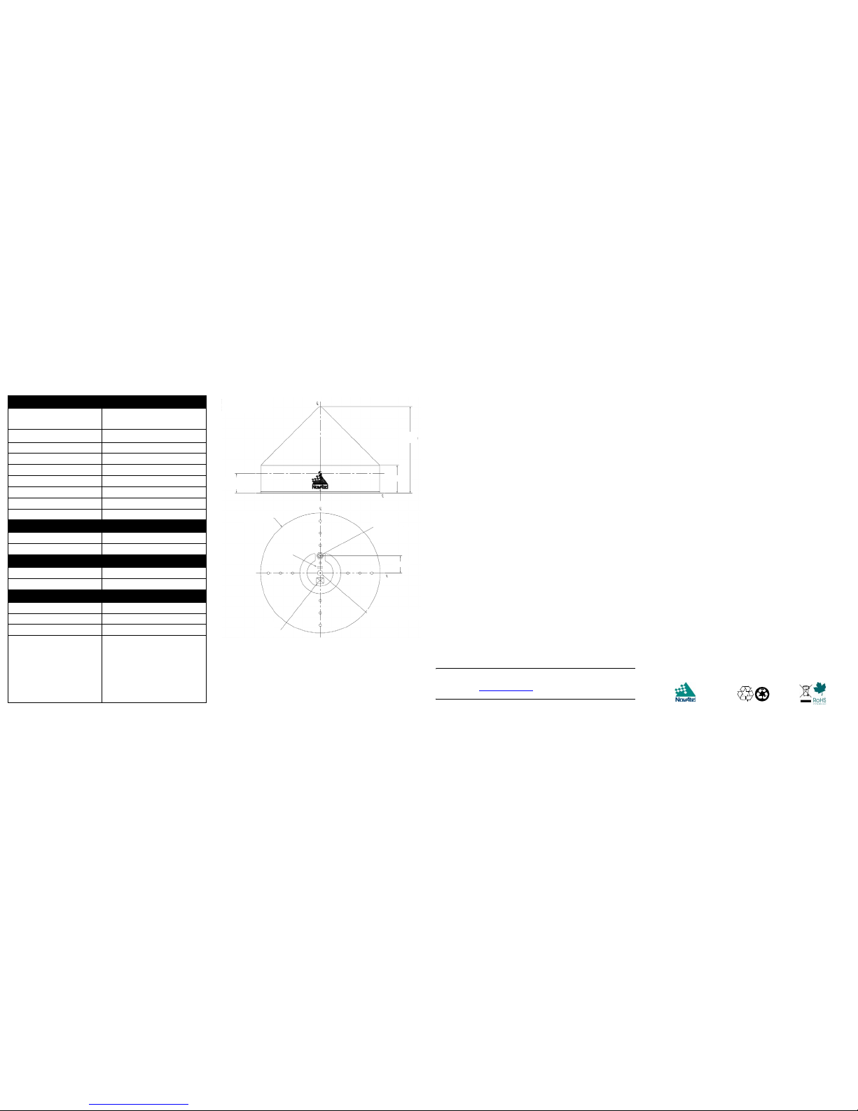
PHYSICAL
Diameter
308 mm (12.12
")
Weight 4.1 kg (9.1 lb.)
ENVIRONMENTAL
Maximum altitude 9144 m (30000 ft)
Operating temperature -55°C to +85°C (-67°F to +185°F)
Storage temperature -55°C to +85°C (-67°F to +185°F)
Design standards
D0-160D
DO228
MIL-C-5541
MIL-E-5400
MIL-I-45208A
MIL-STD-810
SO-C144
SAE J1455
Dimensions are in inches
followed by [mm] and
8.774 [222.85]
2.846 [72.30]
∅12.120 [∅307.65]
∅ denotes diameter
TNC or N-Type Connector
1.750 [44.45]
Date Stamp
Approximate
Location
As Shown
Nameplate
Approximate
Location
Helix Coil:
THD
0.625-11UNC-2Bx0.52” Deep
Phase Center: x=y=0
z=2.000 [50.80] from bottom
for both L1 and L2
 Loading...